WO2014147961A1 - 電子機器冷却装置およびこれを備える電力変換装置 - Google Patents
電子機器冷却装置およびこれを備える電力変換装置 Download PDFInfo
- Publication number
- WO2014147961A1 WO2014147961A1 PCT/JP2014/000920 JP2014000920W WO2014147961A1 WO 2014147961 A1 WO2014147961 A1 WO 2014147961A1 JP 2014000920 W JP2014000920 W JP 2014000920W WO 2014147961 A1 WO2014147961 A1 WO 2014147961A1
- Authority
- WO
- WIPO (PCT)
- Prior art keywords
- chamber
- side wall
- housing
- electronic device
- refrigerant
- Prior art date
- Legal status (The legal status is an assumption and is not a legal conclusion. Google has not performed a legal analysis and makes no representation as to the accuracy of the status listed.)
- Ceased
Links
Images





Classifications
-
- H—ELECTRICITY
- H05—ELECTRIC TECHNIQUES NOT OTHERWISE PROVIDED FOR
- H05K—PRINTED CIRCUITS; CASINGS OR CONSTRUCTIONAL DETAILS OF ELECTRIC APPARATUS; MANUFACTURE OF ASSEMBLAGES OF ELECTRICAL COMPONENTS
- H05K7/00—Constructional details common to different types of electric apparatus
- H05K7/20—Modifications to facilitate cooling, ventilating, or heating
- H05K7/20009—Modifications to facilitate cooling, ventilating, or heating using a gaseous coolant in electronic enclosures
- H05K7/20136—Forced ventilation, e.g. by fans
- H05K7/20145—Means for directing air flow, e.g. ducts, deflectors, plenum or guides
-
- H—ELECTRICITY
- H02—GENERATION; CONVERSION OR DISTRIBUTION OF ELECTRIC POWER
- H02M—APPARATUS FOR CONVERSION BETWEEN AC AND AC, BETWEEN AC AND DC, OR BETWEEN DC AND DC, AND FOR USE WITH MAINS OR SIMILAR POWER SUPPLY SYSTEMS; CONVERSION OF DC OR AC INPUT POWER INTO SURGE OUTPUT POWER; CONTROL OR REGULATION THEREOF
- H02M7/00—Conversion of AC power input into DC power output; Conversion of DC power input into AC power output
- H02M7/003—Constructional details, e.g. physical layout, assembly, wiring or busbar connections
-
- H—ELECTRICITY
- H05—ELECTRIC TECHNIQUES NOT OTHERWISE PROVIDED FOR
- H05K—PRINTED CIRCUITS; CASINGS OR CONSTRUCTIONAL DETAILS OF ELECTRIC APPARATUS; MANUFACTURE OF ASSEMBLAGES OF ELECTRICAL COMPONENTS
- H05K7/00—Constructional details common to different types of electric apparatus
- H05K7/20—Modifications to facilitate cooling, ventilating, or heating
- H05K7/20009—Modifications to facilitate cooling, ventilating, or heating using a gaseous coolant in electronic enclosures
- H05K7/202—Air circulating in closed loop within enclosure wherein heat is removed through heat-exchangers
-
- H—ELECTRICITY
- H05—ELECTRIC TECHNIQUES NOT OTHERWISE PROVIDED FOR
- H05K—PRINTED CIRCUITS; CASINGS OR CONSTRUCTIONAL DETAILS OF ELECTRIC APPARATUS; MANUFACTURE OF ASSEMBLAGES OF ELECTRICAL COMPONENTS
- H05K7/00—Constructional details common to different types of electric apparatus
- H05K7/20—Modifications to facilitate cooling, ventilating, or heating
- H05K7/20218—Modifications to facilitate cooling, ventilating, or heating using a liquid coolant without phase change in electronic enclosures
- H05K7/20263—Heat dissipaters releasing heat from coolant
-
- H—ELECTRICITY
- H05—ELECTRIC TECHNIQUES NOT OTHERWISE PROVIDED FOR
- H05K—PRINTED CIRCUITS; CASINGS OR CONSTRUCTIONAL DETAILS OF ELECTRIC APPARATUS; MANUFACTURE OF ASSEMBLAGES OF ELECTRICAL COMPONENTS
- H05K7/00—Constructional details common to different types of electric apparatus
- H05K7/20—Modifications to facilitate cooling, ventilating, or heating
- H05K7/20218—Modifications to facilitate cooling, ventilating, or heating using a liquid coolant without phase change in electronic enclosures
- H05K7/20272—Accessories for moving fluid, for expanding fluid, for connecting fluid conduits, for distributing fluid, for removing gas or for preventing leakage, e.g. pumps, tanks or manifolds
-
- H—ELECTRICITY
- H05—ELECTRIC TECHNIQUES NOT OTHERWISE PROVIDED FOR
- H05K—PRINTED CIRCUITS; CASINGS OR CONSTRUCTIONAL DETAILS OF ELECTRIC APPARATUS; MANUFACTURE OF ASSEMBLAGES OF ELECTRICAL COMPONENTS
- H05K7/00—Constructional details common to different types of electric apparatus
- H05K7/20—Modifications to facilitate cooling, ventilating, or heating
- H05K7/2089—Modifications to facilitate cooling, ventilating, or heating for power electronics, e.g. for inverters for controlling motor
- H05K7/20909—Forced ventilation, e.g. on heat dissipaters coupled to components
-
- H—ELECTRICITY
- H05—ELECTRIC TECHNIQUES NOT OTHERWISE PROVIDED FOR
- H05K—PRINTED CIRCUITS; CASINGS OR CONSTRUCTIONAL DETAILS OF ELECTRIC APPARATUS; MANUFACTURE OF ASSEMBLAGES OF ELECTRICAL COMPONENTS
- H05K7/00—Constructional details common to different types of electric apparatus
- H05K7/20—Modifications to facilitate cooling, ventilating, or heating
- H05K7/2089—Modifications to facilitate cooling, ventilating, or heating for power electronics, e.g. for inverters for controlling motor
- H05K7/20909—Forced ventilation, e.g. on heat dissipaters coupled to components
- H05K7/20918—Forced ventilation, e.g. on heat dissipaters coupled to components the components being isolated from air flow, e.g. hollow heat sinks, wind tunnels or funnels
-
- H—ELECTRICITY
- H05—ELECTRIC TECHNIQUES NOT OTHERWISE PROVIDED FOR
- H05K—PRINTED CIRCUITS; CASINGS OR CONSTRUCTIONAL DETAILS OF ELECTRIC APPARATUS; MANUFACTURE OF ASSEMBLAGES OF ELECTRICAL COMPONENTS
- H05K7/00—Constructional details common to different types of electric apparatus
- H05K7/20—Modifications to facilitate cooling, ventilating, or heating
- H05K7/2089—Modifications to facilitate cooling, ventilating, or heating for power electronics, e.g. for inverters for controlling motor
- H05K7/20927—Liquid coolant without phase change
Definitions
- the present invention relates to an electronic device cooling device having a rectangular parallelepiped housing in which a heat-generating component is incorporated, and a power conversion device including the same.
- the casing of the electronic device cooling apparatus has a triple structure having a rectangular parallelepiped inner case, an intermediate case, and an outer case. Components that generate heat are built into the inner case.
- An inner air fan is attached to the inner case, and the side facing the inner air fan is an opening.
- the intermediate case also has a corrugated louver fin that surrounds the inner case and similarly surrounds four surfaces facing the inner case.
- the outer case includes corrugated louver fins that surround the intermediate case and similarly surround four surfaces facing the intermediate case.
- an external air fan is attached to the external case, and the side facing the external air fan is an opening.
- An object of the present invention is to provide an electronic device cooling device capable of efficiently cooling two orthogonal surfaces and a power conversion device including the same.
- an electronic device cooling apparatus is an electronic apparatus cooling device having a rectangular parallelepiped housing in which a heat-generating component is incorporated, and includes the following configurations 1 to 5: It is characterized by having at least.
- Structure 1 In this electronic device cooling device, a side wall fin for heat dissipation is formed on the first side wall surface of the casing, and a bottom fin for heat dissipation is formed on the bottom surface of the casing.
- Configuration 2 Further, in this electronic device cooling apparatus, the side wall fin and the bottom fin are covered with a cover portion from the outside.
- the electronic device cooling apparatus further includes a chamber portion that covers the second side wall surface of the casing facing the direction intersecting the first side wall surface.
- the chamber portion defines a chamber chamber facing the second side wall surface, and the chamber chamber communicates with a space surrounding the inner side of the cover portion.
- the electronic device cooling apparatus further includes a refrigerant supply apparatus.
- the refrigerant supply device supplies the refrigerant from the refrigerant introduction port provided on the outer surface of the chamber portion toward the chamber chamber.
- the electronic device cooling apparatus further includes a flat partition portion disposed in the chamber chamber. The partitioning section partitions obliquely so as to distribute the refrigerant from the refrigerant inlet toward each of the two surfaces of the casing on which the side wall fin and the bottom fin are formed.
- the bottom surface of the housing and the first side wall surface are two surfaces of the rectangular parallelepiped housing that are adjacent to each other and orthogonal to each other.
- the chamber part has defined the chamber chamber which opposes the 2nd side wall surface of the housing
- the chamber chamber communicates with a space surrounding the inner side of the cover portion that covers the two surfaces from the outside.
- a refrigerant introduction port is provided on the outer surface of the chamber portion, and the refrigerant supply device can supply the refrigerant from the refrigerant introduction port into the chamber chamber.
- the refrigerant can be supplied to each of the two surfaces via the chamber chamber by the refrigerant supply device. And, these two surfaces are respectively formed with heat-dissipating fins, and the heat-dissipating fins on the two surfaces are covered with the cover part from the outside, so that the flow of the refrigerant from the refrigerant introduction port It is possible to efficiently dissipate heat from the fin while forming the path around the fin.
- a flat plate-like partitioning portion is disposed in the chamber so as to be partitioned obliquely so as to distribute the coolant from the coolant inlet toward each of the two surfaces of the housing in which the side wall fin and the bottom fin are formed.
- the partition portion includes a protrusion formed integrally with the housing, and the protrusion has a second side wall surface of the housing as a base end portion. In addition, it can be formed to project toward the chamber chamber side.
- the partition portion having a function of distributing the refrigerant from the refrigerant inlet toward each of two mutually adjacent orthogonal surfaces of the rectangular parallelepiped housing is formed integrally with the housing. It is suitable.
- the partition portion is provided as a separate component from the housing, and is detachably mounted in the chamber chamber and has a flat plate surface of its own.
- the tilt angle can be adjusted.
- Such a configuration is suitable for making it possible to adjust the function of distributing the refrigerant from the refrigerant inlet toward each of two surfaces that are adjacent and orthogonal to each other of the rectangular parallelepiped housing.
- the coolant may be water, and a pump may be used for the coolant supply device.
- coolant can be made into air and a ventilation fan can be used for the said refrigerant
- the blower fan is mounted near the first side wall surface of the housing and near the corner formed by one side shared by the two surfaces, and the partition portion has two surfaces. If its flat plate-like surface is arranged along a virtual inclined surface including an angle formed by one side shared by each other, one air blower fan can make each of the surfaces adjacent to each other perpendicular to each other. This is more suitable for distributing a desired air flow rate according to the heat generation ratio.
- the refrigerant introduction port is opened in a rectangular shape, and the rectangular opening has one diagonal direction in the inclination direction of the flat surface of the partition portion. It is preferable to arrange along. Such a configuration is even more suitable for efficiently cooling by distributing the air blown from the blower fan toward each of two mutually adjacent and orthogonal surfaces of the rectangular parallelepiped housing.
- a power conversion device includes an electronic device cooling device having a rectangular parallelepiped housing in which a heat generating component is incorporated, and at least power is used as the heat generating component.
- the conversion control unit is built in the casing, and has a control connector, an input connector, and an output connector attached to the casing. When a control signal is input to the control connector, the conversion control unit is input to the input connector.
- the electronic device cooling device since the electronic device cooling device according to one aspect of the present invention is provided, according to the heat generation ratio of each surface with respect to two surfaces that are adjacent and orthogonal to each other.
- the refrigerant can be distributed to the desired amount. Therefore, according to this power converter, two surfaces which are adjacent to each other and orthogonal to each other in the rectangular parallelepiped housing can be efficiently cooled.
- the rectangular parallelepiped casings are adjacent to each other and orthogonal to each other. The two surfaces can be efficiently cooled.
- FIG. 1 is a perspective view illustrating an appearance of a first embodiment (an example in which a refrigerant is air) of a power conversion device including an electronic device cooling device according to an aspect of the present invention.
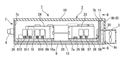
- FIG. 2 is a cross-sectional view taken along line AA in FIG.
- FIG. 3 is a cross-sectional view taken along line BB in FIG. 2. It is a principal part enlarged view of FIG. It is the top view which removed the cover of the power converter of a first embodiment, and showed the inside.
- FIG. 12 is a cross-sectional view taken along the line CC of FIG.
- FIG. 12 is a cross-sectional view taken along line DD in FIG. 11.
- the power conversion device 1 includes a rectangular parallelepiped housing 2.
- a blower fan 3 as a refrigerant supply device is externally attached to the casing 2 on one side surface in the longitudinal direction.
- An input connector 4, a control connector 5, and an output connector 6 are provided in parallel on the other side surface of the casing 2 in the longitudinal direction.
- a power conversion control unit, which will be described later, is built in the housing 2. When a control signal is input to the control connector 5, the commercial power input to the input connector 4 is converted from AC to DC by the power conversion control unit. Thus, it is output from the output connector 6 as DC power.
- the rectangular parallelepiped casing 2 includes a case 7, a chamber forming wall 8, a casing cover 9, and a lid 10, as shown in FIG.
- the case 7 has a bottomed box shape and has a rectangular shape in plan view. As shown in FIG. 5, the bottom 7a having a rectangular shape and a pair of short side walls 7b and 7c rising from four sides of the bottom 7a. , And a pair of long side walls 7d, 7e.
- the case 7 is formed, for example, by die-casting aluminum having a high thermal conductivity or an aluminum alloy.
- the chamber forming wall 8 is disposed on one side of the case 7 in the longitudinal direction, and a predetermined gap is provided between the side wall of the case 7.
- the housing cover 9 is provided so as to cover the case 7 and a part of the chamber forming wall 8.
- the lid 10 is provided so as to close the inside of the housing 2 by closing the upper openings of the case 7 and the chamber forming wall 8.
- the chamber forming wall 8 includes a contact wall 8a that contacts one short side wall 7b of the case 7 and a counter wall 8b that faces one short side wall 7b. It is composed.
- a plurality of side wall fins 12 extending in the longitudinal direction are formed in one long side wall 7e of the case 7 in a region from the lower end to the upper part on the outer side. .
- the plurality of side wall fins 12 are formed in parallel at a predetermined interval in the vertical direction of the long side wall 7e.
- the fin height of each side wall fin 12 is set to H1
- the pitch of the side wall fins 12 is set to P1.
- no side wall fin is formed outside the other long side wall 7 d of the case 7.
- FIG. 1 the fin height of each side wall fin 12 is set to H1
- P1 the pitch of the side wall fins 12
- a plurality of bottom fins 13 extending in the longitudinal direction are also formed in the bottom portion 7 a of the case 7 in the region from the left end portion to the right side of the lower surface thereof.
- the plurality of bottom fins 13 are formed in parallel with a predetermined interval in the short direction of the bottom 7a.
- the fin height of each bottom fin 13 is set to a value H2 (H2> H1) larger than the fin height H1 of the side wall fin 12.
- the pitch of the bottom fins 13 is set to a value P2 (P2> P1) larger than the pitch P1 of the side wall fins 12.
- the housing cover 9 is a cover that covers the side wall fins 12 and the bottom fins 13 from the outside. As shown in FIGS. 3 and 5, the bottom 7 a of the case 7 and the lower openings of the chamber forming wall 8 are formed. A rectangular plate-shaped bottom plate 9a that covers the base plate 9a and a pair of side plates 9b and 9c that rise from the edge of the bottom plate 9a and that cover the side portions of the pair of long side walls 7d and 7e and the chamber forming wall 8 of the case 7 are formed. . As shown in FIG.
- the space between the plurality of side wall fins 12 and the plurality of bottom fins 13 are formed on the outer periphery of the bottom 7a of the case 7 and the one long side wall 7e covered with the housing cover 9 as described above.
- the space between is a plurality of flow paths 27 and 28 extending in the longitudinal direction of the case 7.
- the lid 10 is fixed to the case 7 and the chamber forming wall 8 so as to close the upper openings of the case 7 and the chamber forming wall 8.
- an inner space surrounded by one short side wall 7 b of the case 7, the chamber forming wall 8, the housing cover 9, and the lid body 10 is defined as a chamber chamber 11. .
- An opening 8c is formed in the facing wall 8b of the chamber forming wall 8 as a refrigerant inlet.
- the blower fan 3 is mounted at the position of the opening 8c so that the blower port of the blower fan 3 opposes, and the cooling air generated by the blower fan 3 is sent to the chamber chamber 11 as a refrigerant. It has become.
- a flat partition 30 is provided inside the chamber 11.
- the partition portion 30 includes two long side walls 7e and a bottom plate 9a (hereinafter referred to as “long side walls 7e and bottom plates 9a”) of the case 7, which are two surfaces that are adjacent to each other and orthogonal to each other. It is a partition member that distributes the air blown from the blower fan 3 toward each other.
- the partition part 30 of this embodiment is comprised from the protrusion part integrally formed with the case 7 by the die-cast molding to the case 7 which comprises the housing
- the blower fan 3 of the present embodiment is mounted at a position near the corner (reference symbol K shown in FIGS. 3 and 4) formed by one side shared by the two surfaces 7a and 7e of the housing 2.
- the partition portion 30 has its flat plate-like surface arranged along a virtual inclined surface (reference symbol Lk shown in FIG. 3) including an angle K formed by one side shared by the two surfaces 7a and 7e.
- the opening 8c of the present embodiment is opened in a rectangular shape (substantially square in the example in the figure) whose sides are parallel to the two surfaces 7a and 7e.
- the rectangular opening 8c is arranged so that the direction of one of the diagonal lines substantially coincides with the inclination direction of the flat surface of the partition portion 30.
- the “virtual inclined surface Lk including the corner K” an arbitrary virtual surface passing through an arbitrary point on the opening 8c and the point of the corner K can be selected, and the extending direction of the virtual inclined surface Lk 3 is a direction along a plurality of flow paths 27 and 28 extending in the longitudinal direction of the case 7.
- a virtual inclined surface Lk in the center of the figure inclined at approximately 45 ° is the center, and a range indicated by a symbol (Lk) above and below this corresponds to the heat generation ratio of each surface 7a, 7e.
- the virtual inclined surface Lk can be set as appropriate so as to obtain a desired air flow rate.
- the point of the corner K does not strictly mean the corner of the housing 2 and includes the vicinity of the corner K without departing from the spirit of the present invention.
- the rectangular opening 8c as in the present embodiment is formed, the opening that is closest to the angle K formed by one side shared by the two surfaces 7a and 7e.
- the corner of 8c (K ′ in FIG. 4) can be selected as a reference.
- the power conversion control unit includes a base substrate 15, an input side noise filter unit 16, a first reactor 17, a second reactor 18, an electric field capacitor group 19, a transformer 20, and an output side noise filter unit. 21 and a plurality of semiconductor devices (for example, MOS-FETs) D1 to D12 and first to third circuit boards 23 to 25, and the like.
- semiconductor devices for example, MOS-FETs
- the base substrate 15 is a member having a rectangular shape smaller than the planar shape of the bottom 7a of the case 7 and having a notch 15a formed on one long side.
- the base substrate 15 is provided with a predetermined wiring pattern (not shown) for connecting to the input connector 4, the control connector 5 and the output connector 6 described above.
- the base substrate 15 is fixed by bolting on a support base 26 formed on the upper surface of the bottom 7a of the case 7 with the notch 15a facing the one long side wall 7e of the case 7 (FIG. 2). reference).
- the input side noise filter unit 16, the first reactor 17, the second reactor 18, the electric field capacitor group 19, the output side noise filter unit 21, the semiconductor devices D1 to D12, and the first to third circuits are formed on the base substrate 15.
- the substrates 23 to 25 are mounted, the transformer 20 disposed inside the notch 15a of the base substrate 15 is fixed so as to be in direct contact with the bottom 7a of the case 7, and the internal fan 14 is mounted on the base substrate 15. Is arranged.
- the semiconductor devices D1 to D6 are mounted at a predetermined interval in the alignment direction along one short side of the base substrate 15.
- the positions of the semiconductor devices D1 to D6 are mounted so as to be in direct contact with one short side wall 7b of the case 7 that defines the chamber chamber 11.
- the other semiconductor devices D7 to D12 are mounted at a predetermined interval in the alignment direction along one long side of the base substrate 15.
- the positions of these semiconductor devices D2 to D12 are mounted so as to be in direct contact with one long side wall 7e of the case 7 in which the side wall fins 12 are formed.
- the third circuit board 25 extends in the longitudinal direction and is mounted at the center position in the short direction of the base substrate 15.
- the second circuit board 24 is mounted on the base board 15 so as to extend in the longitudinal direction at a position close to the other short side wall 7c of the case 7 while standing parallel to the third circuit board 25.
- the input side noise filter unit 16, the first reactor 17, the second reactor 18, and the electric field capacitor group 19 are located between the third circuit board 25 and the other long side wall 7d of the case 7 so as to be positioned between the base board. 15 is implemented.
- the output-side noise filter unit 21 is mounted on the base substrate 15 so as to be positioned between the second circuit board 24 and one long side wall 7e of the case 7.
- the internal fan 14 is disposed on a base substrate 15 surrounded by the transformer 20, the third circuit board 25, one short side wall 7b of the case 7, and one long side wall 7e.
- the cooling air is sent in a direction toward the transformer 20 (in the direction of the arrow in FIG. 5).
- the second circuit board 23 is located between the internal fan 14 and one long side wall 7e of the case 7, and has a wind direction function for guiding the cooling air generated by the internal fan 14 to the transformer 20.
- the operation of the power conversion device 1, the cooling function of the electronic device cooling device provided therein, and the function and effect thereof will be described.
- the commercial power input to the input connector 4 is converted from AC to DC by the power conversion control unit housed in the case 7, and output. It is output as DC power from the connector 6.
- control components such as the transformer 20 and the power conversion control unit in the case 7 generate heat, and in particular, the self-heating of the semiconductor devices D1 to D12, the transformer 20, the first reactor, the second reactor, and the electric field capacitor group 19 is high. Become.
- the electronic device cooling device included in the power conversion device 1 includes the chamber chamber 11 and the blower fan 3, and the bottom portion 7a of the case 7 and the long side wall 7e are formed in a rectangular parallelepiped housing.
- the blower fan 3 When the blower fan 3 is driven, the air taken in from the outside is fed into the chamber chamber 11 as cold air.
- the cold air sent into the chamber chamber 11 flows into the plurality of channels 28 formed on the bottom 7a side of the case 7 communicating with the chamber chamber 11 and the plurality of channels 27 formed on the one long side wall 7e side.
- the third circuit board 25 and the second circuit board 24 that are mounted by standing at the center position in the short direction of the base substrate 15 function as wind direction plates, As indicated by the broken-line arrows in FIG. 7, a flow of cold air is generated in the order of the transformer 20, the output side noise filter unit 21, the input side noise filter unit 16, the first reactor, the second reactor, and the electric field capacitor group 19.
- the chamber chamber 11 is disposed opposite to the short side wall 7b facing the direction intersecting with the long side wall 7e, and the opposing wall 8b defining the chamber chamber 11 is disposed.
- blower fan 3 that blows air toward the inside of the chamber chamber 11 from the rectangular opening 8c serving as the refrigerant introduction port is mounted on the outer surface of the fan, as shown by arrows Ra and Rb in FIG.
- a single blower fan 3 can blow air toward the two surfaces 7a and 7e through the chamber chamber 11.
- the air flow path 27 by the blower fan 3 is used. , 28 can be efficiently radiated from the fins 12, 13 while forming them around the fins 12, 13.
- the semiconductor devices D1 to D6 are mounted so as to be in direct contact with one short side wall 7b of the case 7 serving as a cooling body by the cold air flowing into the chamber chamber 11, so that the semiconductor devices D1 to D6 are mounted.
- the heat generated in step 1 is efficiently radiated to one of the short side walls 7b, and the semiconductor devices D1 to D6 can be reliably cooled.
- the semiconductor devices D7 to D12 are mounted so as to be in direct contact with one long side wall 7e of the case 7 serving as a cooling body, the long side wall as shown by the arrow Rb in FIG. By flowing through the plurality of flow paths 27 of 7e, the heat generated in the semiconductor devices D7 to D12 is efficiently radiated to one of the long side walls 7e, and the semiconductor devices D7 to D12 can be reliably cooled.
- the transformer 20 is fixed so as to be in direct contact with the bottom 7a of the case 7 serving as a cooling body, cold air passing through the chamber chamber 11 is formed on the bottom 7a as indicated by an arrow Ra in FIG.
- the heat generated in the transformer 20 is efficiently radiated to the bottom portion 7a and can be reliably cooled.
- the heat inside the casing 2 generated by the first reactor, the second reactor, and the electric field capacitor group 19 is reliably cooled by the cold air circulating in the case 7 generated by driving the internal fan 14.
- the cold air circulating through the case 7 is radiated in contact with one short side wall 7b and one long side wall 7e of the case 7 which is a cooling body, and the bottom 7a of the case 7, so that the first reactor,
- the cooling effect can be enhanced by circulating cool air around the second reactor and the electric field capacitor group 19.
- a flat plate-like partition portion 30 that divides the air blown from the blower fan 3 obliquely toward the two surfaces 7 a and 7 e is provided inside the chamber chamber 11. Since they are arranged, it is possible to distribute a desired air flow rate according to the heat generation ratio of each surface 7a, 7e to two surfaces 7a, 7e that are adjacent to each other and orthogonal to each other. Therefore, according to the electronic device cooling device provided in the power conversion device 1, the two surfaces 7a and 7e that are adjacent to each other and orthogonal to each other in the rectangular parallelepiped housing 2 can be efficiently cooled.
- the blower fan 3 is mounted at a position near the corner K formed by one side shared by the two surfaces 7a and 7e, which is close to the long side wall 7e of the housing 2, and the partition portion 30 has two Since the flat plate-like surface is arranged along the virtual inclined surface Lk including the angle K formed by one side shared by the surfaces 7a and 7e, the two blowers 3 are adjacent to each other and orthogonal to each other. It is suitable for distributing a desired air flow rate according to the heat generation ratio of the surfaces 7a and 7e to the surfaces 7a and 7e.
- the opening 8c which is the refrigerant inlet of the chamber chamber 11, is opened in a rectangular shape, and the direction of one of the diagonal openings is the inclination direction of the flat surface of the partition portion 30.
- the partition portion 30 includes a protruding portion formed integrally with the case 7 constituting the housing 2, and this protruding portion has a short side wall 7b as a base end portion and projects toward the chamber chamber 11 side.
- the function of distributing the air blown from the blower fan 3 toward the two adjacent surfaces 7a, 7e of the rectangular parallelepiped housing 2 that are orthogonal to each other is formed integrally with the housing 2. It is suitable.
- the electronic device cooling device and the power conversion device including the same are not limited to the above-described embodiments, and various modifications can be made without departing from the spirit of the present invention.
- the flat partition portion 30 has been described as an example in which the protrusion 7 is integrally formed on the case 7 constituting the housing 2 by die casting, but the present invention is not limited thereto. is not.
- the partition portion 30 can be provided as a separate part from the case 7 and can be detachably mounted inside the chamber chamber 11, and in this case, the inclination angle of its own flat surface can be adjusted. Can be configured.
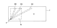
- FIG. 8 shows a modification of such a configuration.
- the partition part 30 is a separate part from the case 7, it is desired that the two surfaces 7a and 7e adjacent to each other are orthogonal to each other according to the heat generation ratio of the surfaces 7a and 7e. This is suitable for distributing the amount of blown air.
- the partition part 30 as a separate part may be fastened and fixed to the short side wall 7b on the case 7 side by screws or the like, or may be fastened and fixed to the inner wall surface on the chamber chamber 11 side by screws or the like.
- the tilt angle is configured to be adjustable, in the example shown in the figure, when the air flow directed toward the long side wall 7e (side fin 12 side) and the bottom plate 9a (bottom fin 13 side) is distributed.
- the partition part 30 is attached to the opening 30c at the position 30B (position near the long side wall 7e with an inclination angle larger than 45 °) with respect to the opening 8c, the long side wall 7e (side wall fin 12 side) is reached.
- the amount of air blown to the bottom plate 9a (bottom fin 13 side) can be made larger than the amount of air blown.
- the partition part 30 is attached to the position of 30A in the figure with respect to the opening part 8c (position where the inclination angle of the virtual inclined surface Lk is about 45 °), the long side wall 7e (side wall fin 12 side). Can be made substantially equal to the amount of air blown to the bottom plate 9a (bottom fin 13 side). Moreover, if the partition part 30 is attached to the position of 30C in the same figure (position near the bottom plate 9a whose inclination angle is smaller than 45 °) with respect to the opening 8c, the long side wall 7e (side wall fin 12 side) The amount of air blown to the bottom plate 9a (bottom fin 13 side) can also be reduced from the amount of air blown.
- a plurality of types of partition portions can be prepared (in the example of the same figure, the length of the plate is different (30A ⁇ 30B ⁇ 30C), It is suitable for distributing a desired air flow rate according to the heat generation ratio of each surface according to appropriate conditions.
- the angle of the virtual inclined surface Lk is used as the reference angle for the above-described opening 8c.
- the corner K ′ is selected.
- air is used as the refrigerant and a blower fan is provided as the refrigerant supply device.
- the present invention is not limited to this, and water may be used as the refrigerant.
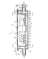
- the second embodiment will be described with reference to FIGS.
- the second embodiment is an example in which water is used as the refrigerant and a pump is provided as the refrigerant supply device.
- this 2nd embodiment is the same as that of said 1st embodiment except the structure according to the point which uses water as a refrigerant
- the same reference numerals as those in the first embodiment are attached and description thereof is omitted.
- the power conversion device 1 according to the second embodiment is used for charging a battery mounted on, for example, an electric vehicle or a hybrid vehicle.
- a heat exchanger 50, a reservoir tank 60, and a pump 70 are provided to circulate cooling water.
- the power conversion device 1 is provided with a cooling water supply port 41 and a cooling water discharge port 42 exposed outside the housing 2.
- the cooling water discharge port 42 is connected to the heat exchanger 50 via a discharge pipe 43.
- An air-cooled radiator or the like mounted on the vehicle can be applied to the heat exchanger 50.
- the cooling water supply port 41 is connected to the pump 70 via a supply pipe 46.
- a reservoir tank 60 for storing cooling water is provided between the heat exchanger 50 and the pump 70, and the reservoir tank 60 is connected to the heat exchanger 50 and the pump 70 by pipes 44 and 45, respectively.
- cooling chamber space surrounding the defining space of the chamber chamber 11 and the side wall fins 12 and the bottom fins 13 communicating with the chamber chamber 11
- portions corresponding to the casing cover 9 and the chamber forming wall 8 are integrally formed.
- the housing cover 9 and the chamber forming wall 8 are integrally formed, for example, by die-casting aluminum or aluminum alloy having high thermal conductivity.
- the housing cover 9 and the chamber forming wall 8 may be formed of separate parts as long as they are securely sealed by packing or the like.
- the lid 10 covering the upper part of the housing 2 is detachable, but there is a packing between the joint surfaces between the upper surface of the housing cover 9 and the chamber forming wall 8 and the back surface of the lid 10. It is intervened.
- flange portions 8 g and 9 g are formed at the upper ends of the housing cover 9 and the chamber forming wall 8.
- the liquid packing 10p is apply
- the upper opening of the chamber chamber 11 and the “cooling chamber” is liquid-sealed to prevent the cooling water from leaking from the back surface portion of the lid 10.
- the side of the short side wall 7c on which the connectors 4, 5, 6 are provided is in an open air state.
- the layout of the connectors 4, 5 and 6 is moved to a position closer to the long side wall 7d, and the long side wall 7e which is the first side wall surface.
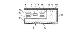
- a space defined by the substantially L-shaped second chamber chamber 11b (in FIG. 12, wall surfaces 9d, 9e, 9f, 9a, 9b and the back surface of the lid body 10) at a location facing the short side wall 7c.
- the side of the short side wall 7c is also sealed.
- the side plate 9b of the housing cover 9 and the long side wall 7d of the case 7 are illustrated on the same plane, this is a schematic illustration, and the chamber chambers 11 and 11b and the “cooling chamber” If the cooling water is prevented from leaking into the case 7 with respect to the side, the position of the side plate 9b and the long side wall 7d in the thickness direction and the mutual division positions can be set as appropriate.
- the cooling water supply port 41 is provided on the outer surface of the opposing wall 8b on the side where the flat partition 30 is disposed so as to communicate with the chamber chamber 11.
- the cooling water discharge port 42 is provided on the outer surface of the side plate 9h opposite to the side where the partition part 30 is disposed so as to communicate with the second chamber chamber 11b.
- the cooling water supply port 41 and the cooling water discharge port 42 are disposed substantially on a coaxial line.
- the partition portion 30 is inclined so as to distribute the refrigerant from the refrigerant inlet toward the two surfaces 7 a and 7 e of the housing 2.
- the cooling water supply port 41 and the cooling water discharge port 42 are both cylindrical pipe members, but the partition portion 30 is a circular opening of the cooling water supply port 41 that is a refrigerant introduction port.
- the position passing through the center of 8c is partitioned diagonally.
- the desired amount according to the heat generation ratio of each surface 7a, 7e is obtained. Cooling water can be distributed.
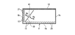
- a flat partition portion 30 that partitions the interior of the chamber chamber 11 obliquely so as to distribute the cooling water from the pump 70 toward the two surfaces 7a and 7e. 10, 11 and 13, as shown by arrows Ra and Rb, the cooling water introduced from the cooling water supply port 41 into the chamber chamber 11 is divided into two surfaces 7 a and 7 e by the partition part 30.
- the rectangular parallelepiped casings are adjacent to each other and orthogonal to each other. The two surfaces can be efficiently cooled.
Landscapes
- Engineering & Computer Science (AREA)
- Microelectronics & Electronic Packaging (AREA)
- Physics & Mathematics (AREA)
- Thermal Sciences (AREA)
- Power Engineering (AREA)
- Cooling Or The Like Of Electrical Apparatus (AREA)
- Rectifiers (AREA)
Abstract
Description
この電子機器冷却装置の筐体は、直方体形状の内ケース、中間ケースおよび外ケースを有する三重構造をなしている。発熱する部品は内ケースに内蔵されている。内ケースには、内気ファンが付設されるとともに、内気ファンと対向する側が開口部とされている。また、中間ケースは、内ケースを囲むとともに内ケースと対向する4面を同様に囲繞するコルゲートルーバーフィンを有する。また、外ケースは、中間ケースを囲むとともに中間ケースと対向する4面を同様に囲繞するコルゲートルーバーフィンを有する。さらに、外ケースには、外気ファンが付設されるとともに、外気ファンと対向する側が開口部とされている。これにより、特許文献1に記載された電子機器冷却装置によれば、内気ファンおよび外気ファンの送風により対流を起こすとともに、ケース相互間の4面を囲繞するコルゲートルーバーフィンにより、内ケース内の熱を効率良く放熱できるとしている。
本発明は、このような問題点に着目してなされたものであって、発熱する部品が内蔵される直方体形状の筐体を有する電子機器冷却装置において、直方体形状の筐体の互いに隣接して直交する二つの面を効率良く冷却することができる電子機器冷却装置およびこれを備える電力変換装置を提供することを目的としている。
(構成1)この電子機器冷却装置は、前記筐体の第一の側壁面に放熱用の側壁フィンが形成されるとともに、前記筐体の底面に放熱用の底部フィンが形成されている。
(構成2)さらに、この電子機器冷却装置は、前記側壁フィンおよび前記底部フィンが外側からカバー部で覆われている。
(構成4)さらに、この電子機器冷却装置は冷媒供給装置を有する。冷媒供給装置は、前記チャンバー部の外側面に設けられた冷媒導入口から前記チャンバー室内に向けて冷媒を供給する。
(構成5)さらに、この電子機器冷却装置は、前記チャンバー室内に配置される平板状の仕切り部を有する。仕切り部は、前記側壁フィンおよび前記底部フィンが形成されている前記筐体の二つの面それぞれに向けて前記冷媒導入口からの冷媒を振り分けるように斜めに仕切る。
また、チャンバー室内には、側壁フィンおよび底部フィンが形成されている筐体の二つの面それぞれに向けて冷媒導入口からの冷媒を振り分けるように斜めに仕切る平板状の仕切り部が配置されているので、互いに隣接して直交する二つの面に対し、各面の発熱比率に応じた所望量に冷媒を振り分けることができる。したがって、この電子機器冷却装置によれば、直方体形状の筐体の互いに隣接して直交する二つの面を効率良く冷却することができる。
冷媒が空気の場合において、送風ファンが、筐体の第一の側壁面寄りであって二つの面相互が共有する一辺がつくる角寄りの位置に装着されるとともに、仕切り部が、二つの面相互が共有する一辺がつくる角を含む仮想傾斜面に沿って自身の平板状の面が配置されていれば、一つの送風ファンによって、互いに隣接して直交する二つの面に対し、各面の発熱比率に応じた所望の送風量を振り分ける上でより好適である。
図1に示すように、この電力変換装置1は、直方体形状の筐体2を有する。この筐体2には、その長尺方向の一方の側面に、冷媒供給装置としての送風ファン3が外付けされている。また、筐体2の長尺方向の他方の側面には、入力コネクタ4、制御コネクタ5、および出力コネクタ6が並列して設けられている。筐体2内には、後述する電力変換制御ユニットが内蔵されており、制御コネクタ5に制御信号を入力すると、入力コネクタ4に入力された商用電力が、電力変換制御ユニットにより交流から直流に変換されて出力コネクタ6から直流電力として出力されるようになっている。
また、図3に示すように、ケース7の底部7aにも、その下面の左端部から右側までの領域に、長尺方向に延在する複数の底部フィン13が形成されている。これら複数の底部フィン13は、底部7aの短尺方向に所定間隔をあけて平行に形成されている。図4に示すように、各底部フィン13のフィン高さは、側壁フィン12のフィン高さH1よりも大きな値H2(H2>H1)に設定されている。さらに、底部フィン13のピッチは、側壁フィン12のピッチP1よりも大きな値P2(P2>P1)に設定されている。
このように、筐体カバー9で覆われたケース7の底部7a及び一方の長辺側壁7eの外周に、図3に示すように、複数の側壁フィン12の間の空間及び複数の底部フィン13の間の空間が、ケース7の長手方向に延在する複数の流路27,28となっている。そして、上記蓋体10が、ケース7及びチャンバー形成壁8の上部開口部を閉塞するようにケース7及びチャンバー形成壁8に固定されている。これにより、ケース7の一方の短辺側壁7bと、チャンバー形成壁8と、筐体カバー9と、蓋体10とで囲まれた内方側の空間が、チャンバー室11として画成されている。
ここで、上記チャンバー室11の内部には、平板状の仕切り部30が設けられている。この仕切り部30は、筐体2の互いに隣接して直交する二つの面となっているケース7の長辺側壁7eと底板9a(以下、これら長辺側壁7eと底板9aとを単に「二つの面」とも呼ぶ)それぞれに向けて送風ファン3からの送風を振り分ける仕切り部材である。なお、本実施形態の仕切り部30は、筐体2を構成するケース7にダイカスト成形によりケース7と一体形成された突出部から構成されている。つまり、この突出部からなる仕切り部30は、ケース7の短辺側壁7bを基端部とするとともにチャンバー11側に向けて張り出し、送風ファン3からの送風を振り分けるように斜めに形成されている。
そして、ベース基板15に、上記の入力側ノイズフィルタ部16、第1リアクトル17、第2リアクトル18、電界コンデンサ群19、出力側ノイズフィルタ部21、半導体デバイスD1~D12及び第1~第3回路基板23~25が実装され、ベース基板15の切欠き部15aの内側に配置したトランス20がケース7の底部7aに直に接触するように固定されているとともに、ベース基板15上に内部ファン14が配置されている。
半導体デバイスD1~D6は、ベース基板15の一方の短辺に沿って並び方向に所定間隔をあけて実装されている。これら半導体デバイスD1~D6の位置は、チャンバー室11を画成しているケース7の一方の短辺側壁7bに直に接触するように実装されている。他の半導体デバイスD7~D12は、ベース基板15の一方の長辺に沿って並び方向に所定間隔をあけて実装されている。これら半導体デバイスD2~D12の位置は、側壁フィン12を形成しているケース7の一方の長辺側壁7eに直に接触するように実装されている。
本実施形態の電力変換装置1は、制御コネクタ5に制御信号を入力すると、入力コネクタ4に入力された商用電力が、ケース7内部に収納した電力変換制御ユニットにより交流から直流に変換され、出力コネクタ6から直流電力として出力される。この際、ケース7内のトランス20や電力変換制御ユニット等の制御部品が発熱し、特に、半導体デバイスD1~D12、トランス20、第1リアクトル、第2リアクトル、電界コンデンサ群19の自己発熱が高くなる。
ここで、上記二つの面7a,7eに対し、長辺側壁7eと交差する方向を向く短辺側壁7bに対向してチャンバー室11が配置されるとともに、チャンバー室11を画成する対向壁8bの外側面には、冷媒導入口となる矩形状の開口部8cからチャンバー室11内に向けて送風をする送風ファン3が装着されているので、図7の矢印Ra、Rbで示すように、一つの送風ファン3によって、チャンバー室11を介して上記二つの面7a,7eそれぞれに向けて送風することができる。そして、この電力変換装置1によれば、上記二つの面7a,7eの放熱用のフィン12,13がその外側から筐体カバー9で覆われているので、送風ファン3による送風の流路27,28をフィン12,13の周囲に形成しつつ、フィン12,13から効率良く放熱することができる。
また、半導体デバイスD7~D12は、冷却体となるケース7の一方の長辺側壁7eに直に接触するように実装されているので、冷風が図7の矢印Rbで示すように、長辺側壁7eの複数の流路27を流れることで、半導体デバイスD7~D12で発生した熱は一方の長辺側壁7eに効率良く放熱され、半導体デバイスD7~D12を確実に冷却することができる。
また、第1リアクトル、第2リアクトル及び電界コンデンサ群19で発生した筐体2内部の熱は、内部ファン14の駆動により発生するケース7内を循環する冷風により確実に冷却される。なお、ケース7を循環する冷風は、冷却体であるケース7の一方の短辺側壁7b及び一方の長辺側壁7e、並びにケース7の底部7aに接触して放熱されるので、第1リアクトル、第2リアクトル及び電界コンデンサ群19の周囲を冷風が循環することで冷却効果を高めることができる。
また、送風ファン3が、筐体2の長辺側壁7e寄りであって二つの面7a,7e相互が共有する一辺がつくる角K寄りの位置に装着されるとともに、仕切り部30が、二つの面7a,7e相互が共有する一辺がつくる角Kを含む仮想傾斜面Lkに沿って自身の平板状の面が配置されているので、一つの送風ファン3によって、互いに隣接して直交する二つの面7a,7eに対し、各面7a,7eの発熱比率に応じた所望の送風量を振り分ける上で好適である。
また、上記仕切り部30は、筐体2を構成するケース7と一体形成された突出部からなり、この突出部は、短辺側壁7bを基端部とするとともにチャンバー室11側に向けて張り出して形成されているので、直方体形状の筐体2の互いに隣接して直交する二つの面7a,7eそれぞれに向けて送風ファン3からの送風を振り分けるという機能を、筐体2と一体形成する上で好適である。
例えば、上記実施形態では、平板状の仕切り部30が、筐体2を構成するケース7にダイカスト成形により一体形成された突出部から構成されている例で説明したが、これに限定されるものではない。例えば、仕切り部30を、ケース7とは別個の部品として設け、チャンバー室11の内部に着脱可能に装着することができ、また、この場合に、自身の平板状の面の傾斜角度を調整可能に構成することができる。図8にこのような構成の変形例を示す。
ここで、傾斜角度を調整可能に構成していれば、同図に示す例において、長辺側壁7e(側壁フィン12側)と底板9a(底部フィン13側)相互に向けた送風量を振り分けるに際し、開口部8cに対して仕切り部30を同図の30Bの位置(傾斜角度が45°よりも大きい長辺側壁7e寄りの位置)に装着すれば、長辺側壁7e(側壁フィン12側)への送風量よりも底板9a(底部フィン13側)への送風量を多くすることができる。
また、例えば上記第一実施形態では、冷媒として空気を用い、冷媒供給装置として送風ファンを設けた例で説明したが、本発明は、これに限らず、冷媒として水を用いてもよい。以下、第二実施形態について図9~13を参照しつつ説明する。
第二実施形態の電力変換装置1は、例えば電気自動車やハイブリッド自動車等に搭載されるバッテリーを充電する用途に用いられる。図9に第二実施形態のシステム構成を示すように、本実施形態では、冷却水を循環させるために、熱交換器50、リザーバタンク60およびポンプ70を備えている。電力変換装置1には、冷却水供給口41と冷却水排出口42とが筐体2の外部に露出して設けられている。冷却水排出口42は、排出用配管43を介して熱交換器50に接続されている。熱交換器50は、車両に搭載された空冷ラジエータ等を適用することができる。冷却水供給口41は、供給用配管46を介してポンプ70に接続されている。熱交換器50とポンプ70との間には、冷却水を貯留するリザーバタンク60が設けられ、リザーバタンク60は、配管44、45によって熱交換器50とポンプ70にそれぞれ接続されている。
ここで、上記第一実施形態では、冷媒が空気なので、チャンバー室11は、完全な密閉が不要であるのに対し、第二実施形態の電力変換装置1では、図10~図13に示すように、チャンバー室11の画成空間、およびチャンバー室11に連通する側壁フィン12と底部フィン13を囲む空間(以下、「冷却室」ともいう)は、周囲が確実に液封され、これにより、チャンバー室11および「冷却室」からの冷却水の漏れが防止されている。
また、筐体2の上部を覆う蓋体10は着脱可能であるが、筐体カバー9およびチャンバー形成壁8の上端面と蓋体10の裏面との間は、相互の接合面間にパッキンが介装されている。本実施形態の例では、筐体カバー9およびチャンバー形成壁8の上端には、フランジ部8g、9gが形成されている。そして、そのフランジ部8g、9gの上面、および筐体カバー9およびチャンバー形成壁8の上端面に、上部開口を囲繞するように液体パッキン10pを塗布しており、蓋体10をねじ等でフランジ部8g、9gに固定することにより、チャンバー室11および「冷却室」の上部開口を液封して、蓋体10の裏面部分から冷却水が漏れること防止している。
2 筐体
3 送風ファン(冷媒供給装置)
4 入力コネクタ
5 制御コネクタ
6 出力コネクタ
7 ケース
7a 底部(筐体の底面)
7b 短辺側壁(第二の側壁面)
7c 短辺側壁
7d 長辺側壁
7e 長辺側壁(第一の側壁面)
8 チャンバー形成壁(チャンバー部)
8a 当接壁
8b 対向壁
8c 開口部(冷媒導入口)
9 筐体カバー(カバー部)
9a 底板
9b,9c 側板
10 蓋体
11 チャンバー室
12 側壁フィン
13 底部フィン
14 内部ファン
15 ベース基板
15a 切欠き部
16 入力側ノイズフィルタ部
17 第1リアクトル
18 第2リアクトル
19 電界コンデンサ群
20 トランス
21 出力側ノイズフィルタ部
23 第1回路基板
24 第2回路基板
25 第3回路基板
26 支持台
27,28 流路
30 仕切り部
41 冷却水供給口(冷媒導入口)
42 冷却水排出口
50 熱交換器
60 リザーバタンク
70 ポンプ(冷媒供給装置)
D1~D12 半導体デバイス
Lk 仮想傾斜面
Claims (8)
- 発熱する部品が内蔵される直方体形状の筐体を有する電子機器冷却装置であって、
前記筐体の第一の側壁面に形成された放熱用の側壁フィンと、前記筐体の底面に形成された放熱用の底部フィンと、前記側壁フィンおよび前記底部フィンを外側から覆うカバー部と、前記第一の側壁面と交差する方向を向く前記筐体の第二の側壁面に対向するチャンバー室を画成するとともに該チャンバー室が前記カバー部よりも内方側を囲む空間に連通するように前記第二の側壁面を覆うチャンバー部と、前記チャンバー部の外側面に設けられた冷媒導入口から前記チャンバー室内に向けて冷媒を供給する冷媒供給装置と、前記チャンバー室内に配置されて前記側壁フィンおよび前記底部フィンが形成されている前記筐体の二つの面それぞれに向けて前記冷媒導入口からの冷媒を振り分けるように斜めに仕切る平板状の仕切り部とを有することを特徴とする電子機器冷却装置。 - 前記仕切り部は、前記筐体と一体形成された突出部からなり、該突出部は、前記筐体の第二の側壁面を基端部とするとともに前記チャンバー室側に向けて張り出して形成されていることを特徴とする請求項1に記載の電子機器冷却装置。
- 前記仕切り部は、前記筐体とは別個の部品として設けられ、前記チャンバー室内に着脱可能に装着されるとともに自身の平板状の面の傾斜角度が調整可能になっていることを特徴とする請求項1に記載の電子機器冷却装置。
- 前記冷媒が水であり、前記冷媒供給装置がポンプであることを特徴とする請求項1に記載の電子機器冷却装置。
- 前記冷媒が空気であり、前記冷媒供給装置が送風ファンであることを特徴とする請求項1に記載の電子機器冷却装置。
- 前記送風ファンは、前記筐体の前記第一の側壁面寄りであって前記二つの面相互が共有する一辺がつくる角寄りの位置に装着されており、前記仕切り部は、前記二つの面相互が共有する一辺がつくる角を含む仮想傾斜面に沿って自身の平板状の面が配置されていることを特徴とする請求項5に記載の電子機器冷却装置。
- 前記冷媒導入口は、矩形形状に開口されており、該矩形形状の開口は、その一方の対角線の向きが、前記仕切り部の平板状の面の傾斜方向に沿って配置されていることを特徴とする請求項6に記載の電子機器冷却装置。
- 発熱する部品が内蔵される直方体形状の筐体を有する電子機器冷却装置を備え、前記発熱する部品として少なくとも電力変換制御ユニットが前記筐体に内蔵されるとともに、前記筐体に付設された制御コネクタ、入力コネクタおよび出力コネクタを有し、前記制御コネクタに制御信号を入力すると、前記入力コネクタに入力された商用電力が、前記電力変換制御ユニットにより交流から直流に変換されて前記出力コネクタから直流電力として出力される電力変換装置であって、
前記電子機器冷却装置として、請求項1~7のいずれか一項に記載の電子機器冷却装置を備えていることを特徴とする電力変換装置。
Priority Applications (4)
| Application Number | Priority Date | Filing Date | Title |
|---|---|---|---|
| CN201480002640.4A CN104704935B (zh) | 2013-03-19 | 2014-02-21 | 电子设备冷却装置以及具备该装置的电力转换装置 |
| EP14768082.1A EP2978291A4 (en) | 2013-03-19 | 2014-02-21 | COOLING DEVICE FOR AN ELECTRONIC DEVICE AND ELECTRICITY TRANSFORMER THEREWITH |
| JP2015506579A JPWO2014147961A1 (ja) | 2013-03-19 | 2014-02-21 | 電子機器冷却装置およびこれを備える電力変換装置 |
| US14/680,559 US9832909B2 (en) | 2013-03-19 | 2015-04-07 | Electronic equipment cooling device and power converter having electronic equipment cooling device |
Applications Claiming Priority (2)
| Application Number | Priority Date | Filing Date | Title |
|---|---|---|---|
| JP2013-056931 | 2013-03-19 | ||
| JP2013056931 | 2013-03-19 |
Related Child Applications (1)
| Application Number | Title | Priority Date | Filing Date |
|---|---|---|---|
| US14/680,559 Continuation US9832909B2 (en) | 2013-03-19 | 2015-04-07 | Electronic equipment cooling device and power converter having electronic equipment cooling device |
Publications (1)
| Publication Number | Publication Date |
|---|---|
| WO2014147961A1 true WO2014147961A1 (ja) | 2014-09-25 |
Family
ID=51579664
Family Applications (1)
| Application Number | Title | Priority Date | Filing Date |
|---|---|---|---|
| PCT/JP2014/000920 Ceased WO2014147961A1 (ja) | 2013-03-19 | 2014-02-21 | 電子機器冷却装置およびこれを備える電力変換装置 |
Country Status (5)
| Country | Link |
|---|---|
| US (1) | US9832909B2 (ja) |
| EP (1) | EP2978291A4 (ja) |
| JP (1) | JPWO2014147961A1 (ja) |
| CN (1) | CN104704935B (ja) |
| WO (1) | WO2014147961A1 (ja) |
Cited By (3)
| Publication number | Priority date | Publication date | Assignee | Title |
|---|---|---|---|---|
| CN111313720A (zh) * | 2019-12-09 | 2020-06-19 | 大唐陕西发电有限公司 | 一种高压直流电源隔离防护装置 |
| KR20240028977A (ko) * | 2021-08-07 | 2024-03-05 | 지디 미디어 히팅 엔드 벤틸레이팅 이큅먼트 코 엘티디 | 전기 제어 박스, 공기조화기 실외기 및 공기조화기 |
| WO2026048417A1 (ja) * | 2024-08-28 | 2026-03-05 | ソニーグループ株式会社 | 電子機器 |
Families Citing this family (13)
| Publication number | Priority date | Publication date | Assignee | Title |
|---|---|---|---|---|
| US9578786B1 (en) * | 2014-06-10 | 2017-02-21 | Amazon Technologies, Inc. | Computer system with bypass air plenum |
| KR101714150B1 (ko) * | 2015-05-11 | 2017-03-09 | 현대자동차주식회사 | 차량용 전력변환 패키지 |
| JP6989386B2 (ja) * | 2015-12-02 | 2022-01-05 | Necネットワーク・センサ株式会社 | 電子部品収容機器および電子装置 |
| US10069407B1 (en) * | 2017-03-02 | 2018-09-04 | Hewlett Packard Enterprise Development Lp | Converters to convert input voltages to output voltages |
| TWM547216U (zh) * | 2017-04-12 | 2017-08-11 | Chyng Hong Electronic Co Ltd | 高功率密度直流轉交直流功率轉換器之抗流圈模組結構 |
| US10921536B2 (en) * | 2017-05-18 | 2021-02-16 | Arista Networks, Inc. | Heat sink for optical transceiver |
| JP6196409B1 (ja) * | 2017-05-26 | 2017-09-13 | Dmg森精機株式会社 | クーラント供給装置 |
| US9966794B1 (en) * | 2017-08-24 | 2018-05-08 | Zippy Technology Corp. | Power supply for redundant power system |
| FR3091461B1 (fr) * | 2019-01-02 | 2020-12-04 | Safran Electrical & Power | Module de distribution électrique compartimenté par des cloisons comportant des canaux de ventilation et/ou de passage de câbles de commande |
| US11464133B2 (en) * | 2019-01-14 | 2022-10-04 | Hewlett Packard Enterprise Development Lp | Cooling container |
| KR102663609B1 (ko) * | 2019-05-03 | 2024-05-07 | 현대자동차주식회사 | 전력변환 장치 |
| CN115704582B (zh) * | 2021-08-07 | 2026-04-07 | 广东美的暖通设备有限公司 | 电控盒、空调室外机和空调器 |
| US12344312B2 (en) | 2023-03-16 | 2025-07-01 | Caterpillar Inc. | Cooling system for electrical systems for work machines |
Citations (8)
| Publication number | Priority date | Publication date | Assignee | Title |
|---|---|---|---|---|
| JPS5360706U (ja) * | 1976-10-27 | 1978-05-23 | ||
| JPS57201086U (ja) * | 1981-06-15 | 1982-12-21 | ||
| JPS5883196U (ja) * | 1981-12-01 | 1983-06-06 | 三菱電機株式会社 | 電子装置 |
| JPS6112290U (ja) * | 1984-06-28 | 1986-01-24 | 三菱電機株式会社 | 電気機器 |
| JPS6257295A (ja) * | 1985-09-06 | 1987-03-12 | 三菱電機株式会社 | 電子機器 |
| JP2002314281A (ja) * | 2001-04-16 | 2002-10-25 | Hitachi Ltd | 冷却水路を備えた電気装置 |
| JP2004006558A (ja) | 2002-04-26 | 2004-01-08 | Denso Corp | 電子機器用冷却装置 |
| JP2012049497A (ja) * | 2010-08-30 | 2012-03-08 | Samsung Electro-Mechanics Co Ltd | 充電モジュール |
Family Cites Families (14)
| Publication number | Priority date | Publication date | Assignee | Title |
|---|---|---|---|---|
| DE3520404C2 (de) * | 1984-06-08 | 1994-06-16 | Genzyme Corp | Schweine-ß-FSH |
| US6019167A (en) * | 1997-12-19 | 2000-02-01 | Nortel Networks Corporation | Liquid immersion cooling apparatus for electronic systems operating in thermally uncontrolled environments |
| JP2002366259A (ja) | 2001-06-11 | 2002-12-20 | Matsushita Electric Ind Co Ltd | 可搬型情報処理装置 |
| US7245485B1 (en) * | 2004-11-15 | 2007-07-17 | Utstarcom, Inc. | Electronics cabinet with internal air-to-air heat exchanger |
| FR2881018B1 (fr) * | 2005-01-19 | 2007-04-06 | Intelligent Electronic Systems | Procede de refroidissement d'un dispositif de conversion statique d'electronique de puissance et dispositif correspondant |
| US7450384B2 (en) * | 2006-07-06 | 2008-11-11 | Hybricon Corporation | Card cage with parallel flow paths having substantially similar lengths |
| FR2926399B1 (fr) * | 2008-01-16 | 2010-02-05 | Intelligent Electronic Systems | Boitier en profiles extrudes metalliques multi-positions pour la fabrication d'un dispositif electronique de puissance etanche |
| US7893365B2 (en) * | 2008-11-10 | 2011-02-22 | Adc Telecommunications, Inc. | Weather resistant variable enclosure frame |
| US7961462B2 (en) * | 2009-05-28 | 2011-06-14 | Alcatel Lucent | Use of vortex generators to improve efficacy of heat sinks used to cool electrical and electro-optical components |
| US20110108250A1 (en) * | 2009-11-09 | 2011-05-12 | Alex Horng | Heat Dissipating device |
| CN103260924B (zh) * | 2010-12-07 | 2016-11-09 | 艾里逊变速箱公司 | 用于混合动力电动车的能量存储系统 |
| US8681501B2 (en) * | 2010-12-17 | 2014-03-25 | Aruba Networks, Inc. | Heat dissipation unit for a wireless network device |
| JP5897478B2 (ja) * | 2013-01-31 | 2016-03-30 | 株式会社東芝 | 電子機器筺体 |
| WO2014147963A1 (ja) | 2013-03-19 | 2014-09-25 | 富士電機株式会社 | 冷却装置及びこれを備えた電力変換装置 |
-
2014
- 2014-02-21 WO PCT/JP2014/000920 patent/WO2014147961A1/ja not_active Ceased
- 2014-02-21 CN CN201480002640.4A patent/CN104704935B/zh not_active Expired - Fee Related
- 2014-02-21 JP JP2015506579A patent/JPWO2014147961A1/ja active Pending
- 2014-02-21 EP EP14768082.1A patent/EP2978291A4/en not_active Withdrawn
-
2015
- 2015-04-07 US US14/680,559 patent/US9832909B2/en not_active Expired - Fee Related
Patent Citations (8)
| Publication number | Priority date | Publication date | Assignee | Title |
|---|---|---|---|---|
| JPS5360706U (ja) * | 1976-10-27 | 1978-05-23 | ||
| JPS57201086U (ja) * | 1981-06-15 | 1982-12-21 | ||
| JPS5883196U (ja) * | 1981-12-01 | 1983-06-06 | 三菱電機株式会社 | 電子装置 |
| JPS6112290U (ja) * | 1984-06-28 | 1986-01-24 | 三菱電機株式会社 | 電気機器 |
| JPS6257295A (ja) * | 1985-09-06 | 1987-03-12 | 三菱電機株式会社 | 電子機器 |
| JP2002314281A (ja) * | 2001-04-16 | 2002-10-25 | Hitachi Ltd | 冷却水路を備えた電気装置 |
| JP2004006558A (ja) | 2002-04-26 | 2004-01-08 | Denso Corp | 電子機器用冷却装置 |
| JP2012049497A (ja) * | 2010-08-30 | 2012-03-08 | Samsung Electro-Mechanics Co Ltd | 充電モジュール |
Non-Patent Citations (1)
| Title |
|---|
| See also references of EP2978291A4 * |
Cited By (7)
| Publication number | Priority date | Publication date | Assignee | Title |
|---|---|---|---|---|
| CN111313720A (zh) * | 2019-12-09 | 2020-06-19 | 大唐陕西发电有限公司 | 一种高压直流电源隔离防护装置 |
| CN111313720B (zh) * | 2019-12-09 | 2024-03-29 | 大唐陕西发电有限公司 | 一种高压直流电源隔离防护装置 |
| KR20240028977A (ko) * | 2021-08-07 | 2024-03-05 | 지디 미디어 히팅 엔드 벤틸레이팅 이큅먼트 코 엘티디 | 전기 제어 박스, 공기조화기 실외기 및 공기조화기 |
| JP2024520036A (ja) * | 2021-08-07 | 2024-05-21 | 広東美的暖通設備有限公司 | 電気制御ボックス、エアコン室外機及びエアコン |
| JP7718768B2 (ja) | 2021-08-07 | 2025-08-05 | 広東美的暖通設備有限公司 | 電気制御ボックス、エアコン室外機及びエアコン |
| KR102927717B1 (ko) * | 2021-08-07 | 2026-02-13 | 지디 미디어 히팅 엔드 벤틸레이팅 이큅먼트 코 엘티디 | 전기 제어 박스, 공기조화기 실외기 및 공기조화기 |
| WO2026048417A1 (ja) * | 2024-08-28 | 2026-03-05 | ソニーグループ株式会社 | 電子機器 |
Also Published As
| Publication number | Publication date |
|---|---|
| US9832909B2 (en) | 2017-11-28 |
| CN104704935B (zh) | 2016-08-17 |
| US20150216077A1 (en) | 2015-07-30 |
| CN104704935A (zh) | 2015-06-10 |
| JPWO2014147961A1 (ja) | 2017-02-16 |
| EP2978291A1 (en) | 2016-01-27 |
| EP2978291A4 (en) | 2016-11-02 |
Similar Documents
| Publication | Publication Date | Title |
|---|---|---|
| WO2014147961A1 (ja) | 電子機器冷却装置およびこれを備える電力変換装置 | |
| JP5971403B2 (ja) | 冷却装置及びこれを備えた電力変換装置 | |
| CN102573412B (zh) | 带冷却功能的控制装置 | |
| US9661783B2 (en) | Magnetic component cooling structure and power converter having the same | |
| US20120057302A1 (en) | Cooling apparatus and electronic equipment | |
| CN103687440A (zh) | 散热器、电子设备以及冷却设备 | |
| JP2006054215A (ja) | 電子機器の放熱構造 | |
| JPWO2014147960A1 (ja) | 磁気部品の冷却構造及びこれを備えた電力変換装置 | |
| JP7139684B2 (ja) | 冷却装置、及び電子機器 | |
| KR100618491B1 (ko) | 공기 조화기의 실외기 | |
| CN114928984B (zh) | 冷板组件、集成域控制器及车辆 | |
| CN101416306A (zh) | 冷却器 | |
| JP3371651B2 (ja) | 制御盤 | |
| JP2018056370A (ja) | 電源装置 | |
| CN119342751A (zh) | 散热组件及功率变换设备 | |
| CN217159528U (zh) | 具有散热风道的射频电源 | |
| CN216673641U (zh) | 具有散热器外壳的射频电源 | |
| KR102232902B1 (ko) | 냉각모듈을 갖는 전자기기 및 전자기기 어셈블리 | |
| JP2019165549A (ja) | 電力変換装置および蓄電池システム | |
| JP2019175890A (ja) | 放熱装置および電気機器 | |
| CN113207262A (zh) | 一种机箱及供电系统 | |
| CN220693617U (zh) | 散热装置 | |
| CN223182525U (zh) | 一种散热组件和功率变换设备 | |
| CN220674183U (zh) | 散热盒及其电气设备 | |
| JP2019165160A (ja) | 冷却装置、電力変換装置および蓄電池システム |
Legal Events
| Date | Code | Title | Description |
|---|---|---|---|
| 121 | Ep: the epo has been informed by wipo that ep was designated in this application |
Ref document number: 14768082 Country of ref document: EP Kind code of ref document: A1 |
|
| REEP | Request for entry into the european phase |
Ref document number: 2014768082 Country of ref document: EP |
|
| WWE | Wipo information: entry into national phase |
Ref document number: 2014768082 Country of ref document: EP |
|
| ENP | Entry into the national phase |
Ref document number: 2015506579 Country of ref document: JP Kind code of ref document: A |
|
| NENP | Non-entry into the national phase |
Ref country code: DE |