WO2014148032A1 - ロボットシステムの制御方法およびロボットシステム - Google Patents
ロボットシステムの制御方法およびロボットシステム Download PDFInfo
- Publication number
- WO2014148032A1 WO2014148032A1 PCT/JP2014/001499 JP2014001499W WO2014148032A1 WO 2014148032 A1 WO2014148032 A1 WO 2014148032A1 JP 2014001499 W JP2014001499 W JP 2014001499W WO 2014148032 A1 WO2014148032 A1 WO 2014148032A1
- Authority
- WO
- WIPO (PCT)
- Prior art keywords
- robot
- slave
- transformation matrix
- master
- tcp
- Prior art date
- Legal status (The legal status is an assumption and is not a legal conclusion. Google has not performed a legal analysis and makes no representation as to the accuracy of the status listed.)
- Ceased
Links
Images



Classifications
-
- B—PERFORMING OPERATIONS; TRANSPORTING
- B25—HAND TOOLS; PORTABLE POWER-DRIVEN TOOLS; MANIPULATORS
- B25J—MANIPULATORS; CHAMBERS PROVIDED WITH MANIPULATION DEVICES
- B25J9/00—Program-controlled manipulators
- B25J9/16—Program controls
- B25J9/1679—Program controls characterised by the tasks executed
- B25J9/1682—Dual arm manipulator; Coordination of several manipulators
-
- B—PERFORMING OPERATIONS; TRANSPORTING
- B25—HAND TOOLS; PORTABLE POWER-DRIVEN TOOLS; MANIPULATORS
- B25J—MANIPULATORS; CHAMBERS PROVIDED WITH MANIPULATION DEVICES
- B25J3/00—Manipulators of leader-follower type, i.e. both controlling unit and controlled unit perform corresponding spatial movements
-
- B—PERFORMING OPERATIONS; TRANSPORTING
- B25—HAND TOOLS; PORTABLE POWER-DRIVEN TOOLS; MANIPULATORS
- B25J—MANIPULATORS; CHAMBERS PROVIDED WITH MANIPULATION DEVICES
- B25J9/00—Program-controlled manipulators
- B25J9/0084—Program-controlled manipulators comprising a plurality of manipulators
-
- B—PERFORMING OPERATIONS; TRANSPORTING
- B25—HAND TOOLS; PORTABLE POWER-DRIVEN TOOLS; MANIPULATORS
- B25J—MANIPULATORS; CHAMBERS PROVIDED WITH MANIPULATION DEVICES
- B25J9/00—Program-controlled manipulators
- B25J9/16—Program controls
- B25J9/1602—Program controls characterised by the control system, structure, architecture
- B25J9/1607—Calculation of inertia, jacobian matrixes and inverses
-
- G—PHYSICS
- G05—CONTROLLING; REGULATING
- G05B—CONTROL OR REGULATING SYSTEMS IN GENERAL; FUNCTIONAL ELEMENTS OF SUCH SYSTEMS; MONITORING OR TESTING ARRANGEMENTS FOR SUCH SYSTEMS OR ELEMENTS
- G05B2219/00—Program-control systems
- G05B2219/30—Nc systems
- G05B2219/39—Robotics, robotics to robotics hand
- G05B2219/39121—Two manipulators operate on same object
-
- G—PHYSICS
- G05—CONTROLLING; REGULATING
- G05B—CONTROL OR REGULATING SYSTEMS IN GENERAL; FUNCTIONAL ELEMENTS OF SUCH SYSTEMS; MONITORING OR TESTING ARRANGEMENTS FOR SUCH SYSTEMS OR ELEMENTS
- G05B2219/00—Program-control systems
- G05B2219/30—Nc systems
- G05B2219/39—Robotics, robotics to robotics hand
- G05B2219/39132—Robot welds, operates on moving workpiece, moved by other robot
-
- G—PHYSICS
- G05—CONTROLLING; REGULATING
- G05B—CONTROL OR REGULATING SYSTEMS IN GENERAL; FUNCTIONAL ELEMENTS OF SUCH SYSTEMS; MONITORING OR TESTING ARRANGEMENTS FOR SUCH SYSTEMS OR ELEMENTS
- G05B2219/00—Program-control systems
- G05B2219/30—Nc systems
- G05B2219/39—Robotics, robotics to robotics hand
- G05B2219/39139—Produce program of follower from path of leader and desired relative position
-
- Y—GENERAL TAGGING OF NEW TECHNOLOGICAL DEVELOPMENTS; GENERAL TAGGING OF CROSS-SECTIONAL TECHNOLOGIES SPANNING OVER SEVERAL SECTIONS OF THE IPC; TECHNICAL SUBJECTS COVERED BY FORMER USPC CROSS-REFERENCE ART COLLECTIONS [XRACs] AND DIGESTS
- Y10—TECHNICAL SUBJECTS COVERED BY FORMER USPC
- Y10S—TECHNICAL SUBJECTS COVERED BY FORMER USPC CROSS-REFERENCE ART COLLECTIONS [XRACs] AND DIGESTS
- Y10S901/00—Robots
- Y10S901/02—Arm motion controller
- Y10S901/06—Communication with another machine
- Y10S901/08—Robot
Definitions
- the present disclosure relates to a robot system control method and robot system using an industrial robot or the like, and more particularly, to a robot system in which a plurality of robots work in cooperation.
- robot systems are required to work on a wide variety of complex workpieces.
- robot systems are required to be applied to high-mix low-volume production and to reduce the number and installation area of equipment including robots.
- a robot system has been introduced in which a robot that grips a work tool and a robot that grips a workpiece operate in a coordinated manner (hereinafter referred to as a cooperative operation) without using a unique jig for each workpiece.
- FIG. 9 is a diagram showing an example of a conventional robot system using two robots.
- the robot D is a master robot holding the work tool 31.
- the robot E is a slave robot that holds the handling device 34.
- the robot D performs a work in cooperation with the robot E on the workpiece W held by the robot E with the handling device 34.
- a robot holding the work tool is referred to as a “working robot”, and a robot holding the handling device is referred to as a “handling robot”.
- a robot that instructs the slave robot to operate is referred to as a “master robot”, and a robot that operates according to the instruction of the master robot is referred to as a “slave robot”.
- a transformation matrix T DE indicating the positional relationship between the robot coordinate system ⁇ d of the robot D and the robot coordinate system ⁇ e of the robot E is required. is there.
- Each of the robot D and the robot E has a tool center point (hereinafter referred to as TCP) as a control point, and conventionally, the TCP of the robot D and the TCP of the robot E are matched at three points that are not in a straight line.
- TCP alignment This operation is called “TCP alignment”.
- Work robot E is gripped, since represented by the robot coordinate system ⁇ e robot E, the transformation matrix T DE, at the time of cooperative operation, the robot D, indicated by the work coordinate system ⁇ w that the TCP of the robot E and the coordinate origin It can be operated with a trajectory and speed.
- One master robot performs TCP alignment with each of a plurality of slave robots, generates conversion matrices for the number of slave robots, and stores them in the control device. At this time, it is not necessary to perform TCP alignment between slave robots.
- the master robot transmits the teaching robot's teaching point and interpolation point position data to a plurality of slave robots.
- Each of the plurality of slave robots corrects the teaching point or interpolation point of the program of the slave robot itself based on the position data of the teaching point and interpolation point transmitted from the master robot. Thereby, three or more robots are operated in cooperation (for example, refer to Patent Document 1).
- the present disclosure provides a control method of a robot system and a robot system with good work efficiency even when three or more robots are used.
- the control method of the robot system includes a first step to a fifth step.
- a first transformation matrix representing the positional relationship between the master robot and the first slave robot is generated, and the first transformation matrix is stored in the master robot.
- a second transformation matrix representing the positional relationship between the first slave robot and the second slave robot is generated, and the second transformation matrix is stored in the master robot.
- the master robot instructs the operation of the first slave robot based on the first command obtained using the first transformation matrix.
- the master robot instructs the operation of the second slave robot based on the second command obtained using the first transformation matrix and the second transformation matrix.
- the first slave robot and the second slave robot operate in cooperation with the master robot.
- the robot system of the present disclosure includes a master robot, a first slave robot, and a second slave robot.
- the master robot has a first storage unit, a second storage unit, and a first calculation unit.
- the first slave robot and the second slave robot are connected to the master robot.
- the first storage unit stores a first transformation matrix representing a positional relationship between the master robot and the first slave robot.
- the second storage unit stores a second transformation matrix representing the positional relationship between the first slave robot and the second slave robot.
- the first computing unit obtains a first command using the first transformation matrix and instructs the operation of the first slave robot.
- the first computing unit obtains a second command using the first transformation matrix and the second transformation matrix and instructs the operation of the second slave robot.
- the first slave robot and the second slave robot operate in cooperation with the master robot.
- a work robot that cannot perform TCP alignment with all other robots can be used as a master robot, and all robots can be operated cooperatively. Thereby, an operator's work efficiency can be improved.
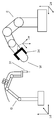
- FIG. 1 is a diagram illustrating a schematic configuration of the robot system according to the first embodiment of the present disclosure.
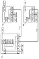
- FIG. 2 is a diagram illustrating an overview of connections between control devices according to the first embodiment of the present disclosure.
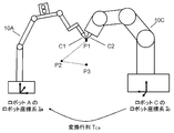
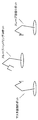
- FIG. 3 is a diagram illustrating TCP alignment for generating a transformation matrix according to the first embodiment of the present disclosure.
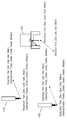
- FIG. 4 is a diagram illustrating a configuration of a target position command in the first embodiment of the present disclosure.
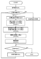
- FIG. 5 is a flowchart of the program execution process according to the first embodiment of the present disclosure.
- FIG. 6 is a diagram for describing the coordinate system of each robot according to the first embodiment of the present disclosure.
- FIG. 7 is a flowchart of the interpolation control process according to the first embodiment of the present disclosure.
- FIG. 8 is a diagram for describing a system configuration according to the first embodiment of the present disclosure.
- FIG. 9 is a diagram showing a conventional robot system.
- FIG. 1 is a diagram illustrating a robot system that performs a welding operation by cooperatively operating three robots in the present embodiment.
- robot A master robot
- robot B second slave robot
- robot C first slave robot
- robot C handling robot that grips a workpiece. It is.
- Robot A includes a manipulator 10A, a welding torch 11A, a welding wire feeding device 12A, a welding wire 13A, a welding machine 14A, and a control device 16A.
- the welding machine 14A is electrically connected to the welding torch 11A and controls the welding current and the welding voltage.
- the welding machine 14A is electrically connected to the welding wire feeding device 12A and controls the feeding speed of the welding wire 13A.
- Robot B has a manipulator 10B, a welding torch 11B, a welding wire feeding device 12B, a welding wire 13B, a welding machine 14B, and a control device 16B.
- the welding machine 14B is electrically connected to the welding torch 11B and controls the welding current and the welding voltage.
- the welding machine 14B is electrically connected to the welding wire feeder 12B and controls the feeding speed of the welding wire 13B.
- the robot C includes a manipulator 10C, a handling device 15C, and a control device 16C, and can hold the workpiece W by the handling device 15C.
- the robot A is controlled by the control device 16A
- the robot B is controlled by the control device 16B. More specifically, control devices 16A and 16B instruct welding conditions such as welding voltage, welding current, and wire feed speed to welding machines 14A and 14B, and also instruct the movement of manipulators 10A and 10B.
- the robots A and B perform the welding operation on the workpiece W by executing this instruction.
- the robot C is controlled by the control device 16C. More specifically, the control device 16C instructs the handling device 15C to open / close the hand of the handling device 15C and also instructs the movement of the manipulator 10C. By executing this instruction, the robot C opens and closes the hand of the handling device 15C to hold, release, and move the workpiece W.
- the robot A is operated as a master robot, and the robot B and the robot C are operated as slave robots.
- the master robot performs communication for causing the slave robot to perform a cooperative operation. Therefore, the control device 16A and the control device 16B are connected by an optical fiber cable 17AB. Further, the control device 16A and the control device 16C are connected by an optical fiber cable 17AC.
- an optical fiber cable that is resistant to electrical noise is used as a communication line that connects between control devices.
- a cable such as a LAN (Local Area Network) or serial communication may be used, or wireless communication without using a communication line may be used.
- the control devices 16A, 16B, and 16C are connected to teach pendants 18A, 18B, and 18C, which are input devices.
- the operator uses the teach pendant to set the operation of the robot, the mode switching between the master mode and the slave mode, and the like in the control device.
- Teach pendants 18A, 18B, and 18C are a robot operation unit (not shown), a mode switching unit (not shown) for switching between a slave robot state and a master robot state, and various data such as welding current and wire feed speed. It has a data display unit (not shown) for displaying, a data setting unit (not shown) for setting various data, and the like.
- FIG. 2 shows the configuration of the control devices 16A, 16B, and 16C.
- the control device 16A for the robot A which is the master robot, includes an arithmetic unit 20A, a teaching data storage unit 21A, a manipulator control unit 22A, a welding condition command unit 23A, a communication unit 24A, and slave robot communication units 25AB and 25AC.
- the arithmetic unit 20A includes a CPU that performs various internal calculations, a memory, and the like.
- the teaching data storage unit 21A stores data taught for a playback operation during automatic operation.
- the manipulator control unit 22A controls the manipulator 10A based on the result calculated by the calculation unit 20A.
- the welding condition command unit 23A commands a welding condition such as a welding current to the welding machine 14A.
- the communication unit 24A communicates with the teach pendant 18A.
- the slave robot communication unit 25AB transmits an operation command and a welding command to the robot B, which is a slave robot, and receives information from the robot B.
- the slave robot communication unit 25AC transmits an operation command and a handling command to the robot C, which is a slave robot, and receives information from the robot C.
- the calibration point storage unit 26AC stores the TCP position and TCP direction vector of each robot necessary for the cooperative operation of the robot A and the robot C.
- the transformation matrix storage unit 27AC stores a transformation matrix T CA (first transformation matrix) between the robot A and the robot C calculated from the data of the calibration point storage unit 26AC.
- the calibration point storage unit 26BC stores the TCP position and TCP direction vector of each robot necessary for the cooperative operation of the robot B and the robot C.
- the transformation matrix storage unit 27BC stores a transformation matrix T CB (second transformation matrix) between the robot B and the robot C calculated from the data of the calibration point storage unit 26BC.
- the control device 16B of the robot B which is a slave robot, includes a calculation unit 20B, a manipulator control unit 22B, a welding condition command unit 23B, a communication unit 24B, and a master robot communication unit 25BA.
- the calculation unit 20B, manipulator control unit 22B, welding condition command unit 23B, communication unit 24B, and the like have the same functions as the control device 16A.
- master robot communication unit 25BA receives an operation command and a welding command from robot A, which is the master robot, and transmits information about robot B.
- the content of data transmitted / received by the master robot communication unit 25BA may be different depending on the role of the robot B, and the control device 16B is connected to the control device 16A so that the robot B can function as a master robot.
- a similar configuration may be used.
- the control device 16C of the robot C which is a slave robot, includes a calculation unit 20C, a manipulator control unit 22C, a handling command unit 26C, a communication unit 24C, and a master robot communication unit 25CA.
- the calculation unit 20C, manipulator control unit 22C, communication unit 24C, and the like have the same functions as the control device 16A.
- master robot communication unit 25CA receives an operation command and a handling command from robot A, which is the master robot, and transmits information about robot C.
- the content of data transmitted and received by the master robot communication unit 25CA may differ depending on the role of the robot C, and the control device 16C is connected to the control device 16A so that the robot C can function as a master robot. A similar configuration may be used.
- the control device 16A for the robot A which is the master robot, stores the teaching points in which the robot A, the robot B, and the robot C form one set in the teaching data storage unit 21A.
- Data stored in the teaching data storage unit 21A is read out by the arithmetic unit 20A during the playback operation.
- the operation unit 20A calculates the operation amount of each robot, and the operation and welding of the robot A are controlled via the manipulator control unit 22A and the welding condition command unit 23A.
- the operation and welding of the robot B which is a slave robot, are controlled by a command transmitted from the control device 16A to the control device 16B via the slave robot communication unit 25AB.
- the control device 16B processes the command from the control device 16A received by the master robot communication unit 25BA by the calculation unit 20B.
- the operation and welding of the robot B are controlled via the manipulator control unit 22B and the welding condition command unit 23B.
- the control device 16B transmits information such as the current posture of the robot B and the welding output state to the control device 16A via the master robot communication unit 25BA.
- the operation and handling of the robot C are controlled by a command transmitted from the control device 16A to the control device 16C via the slave robot communication unit 25AC.
- the command from the control device 16A received by the master robot communication unit 25CA is processed by the calculation unit 20C.
- the operation and handling of the robot C are controlled via the manipulator control unit 22C and the handling command unit 26C.
- the control device 16C transmits information such as the current posture of the robot C and the output state of the handling device 15C to the control device 16A via the master robot communication unit 25CA.
- the conversion matrix indicates a relationship between two different coordinate systems, and thereby, a position vector indicated in one coordinate system can be converted into a position vector indicated in the other coordinate system.
- robot A and robot B that are work robots need to operate in cooperation with robot C that is a handling robot. Therefore, in order to generate the transformation matrix, the positional relationship between the robot A and the robot C and the positional relationship between the robot B and the robot C are required.
- the teaching tip C1 is attached to the welding torch 11A attached to the tip of the manipulator 10A of the robot A. Then, the offset from the wrist tip of the robot A (tip of the manipulator 10A) to the tip of the teaching chip C1 is set correctly. By doing so, the tip of the teaching chip C1 becomes the TCP of the robot A. TCP is a control point of the robot.
- the robot C sets a correct offset value from the wrist tip of the robot C (tip of the manipulator 10C) to the reference point with a part of the handling device 15C attached to the tip of the manipulator 10C as a reference point.
- the center of the tips of both hands of the handling device 15C is set as the reference value. If an appropriate reference point cannot be obtained for the handling device 15C, as shown in FIG. 3, the handling device 15C is removed, and a jig C2 that can reliably take the reference point is attached to the tip of the manipulator 10C of the robot C. May be.
- the reference point provided by either method becomes the TCP of the robot C.
- the operator operates the teach pendant 18C to switch the control device 16C to the slave robot mode.
- the operator uses the teach pendant 18A of the robot A that is the master robot, the operator operates both the robot A that is the master robot and the robot C that is the slave robot.
- the TCP of robot A and the TCP of robot C are at three points (P1, P2, P3) on a space that is not on the same straight line without changing the direction vector of both TCPs. Match.
- the TCP position and TCP direction vector of each robot in the robot coordinate systems ⁇ a and ⁇ c whose origin is the reference point of the robots A and C are stored in the calibration point storage unit 26AC. Then, from the three TCP position data and direction vector data of the robot A and the three TCP position data and direction vector data of the robot C, the robot coordinate system ⁇ c of the robot C is changed to the robot coordinate system ⁇ a of the robot A.
- the conversion matrix T CA can be calculated by the calculation unit 20A.
- the transformation matrix T CA is stored in the transformation matrix storage unit 27AC.
- the teaching tip C1 is attached to the welding torch 11B attached to the tip of the manipulator 10B of the robot B. Then, the offset from the wrist tip of the robot B (tip of the manipulator 10B) to the tip of the teaching chip C1 is set correctly. By doing so, the tip of the teaching chip C1 becomes the TCP of the robot B.
- the operator operates the teach pendant 18B and the teach pendant 18C to switch the control device 16B and the control device 16C to the slave robot mode.
- the operator operates both the robot B and the robot C, which are slave robots, using the teach pendant 18A of the robot A, which is the master robot.
- the TCP of the robot B and the TCP of the robot C are 3 on the space that is not on the same straight line without changing the direction vector of both TCPs. Match with dots.
- the TCP position and TCP direction vector of each robot in the robot coordinate systems ⁇ b and ⁇ c whose origin is the reference point of the robots B and C are stored in the calibration point storage unit 26BC. Then, from the three TCP position data and direction vector data of the robot B and the three TCP position data and direction vector data of the robot C, the robot coordinate system ⁇ c of the robot C is changed to the robot coordinate system ⁇ b of the robot B.
- the conversion matrix T CB can be calculated by the calculation unit 20A.
- the transformation matrix T CB is stored in the transformation matrix storage unit 27BC.
- the TCP of the robot A and the robot B By using these conversion matrix T CA and transformation matrix T CB, the TCP of the robot A and the robot B, it is possible to represent the tip of the manipulator 10C robot C in the workpiece coordinate system ⁇ w that the coordinate origin.
- the TCPs of the robot A and the robot B can be operated in cooperation with the robot C at the speed and locus indicated by the workpiece coordinate system ⁇ w, which is suitable for welding complicated workpieces.
- the calculation unit 20A calls an operation program for operating the robots A to C in cooperation from the teaching data storage unit 21A. Then, the arithmetic unit 20A performs instructions to the robots A to C, processing of information collected from the robots A to C, and the like according to the work procedure indicated by the operation program.
- the operation program is composed of various commands including a target position command which is a command characteristic in the cooperative operation. In the target position command, as shown in FIG. 4, the target angle and the operation speed (rotation speed) of each axis constituting the manipulators 10A to 10C of the robots A to C are linearly operated by TCP between the two points or the curve operation. A command related to the operation of the manipulator, such as whether or not to perform cooperative operation with a plurality of robots, is recorded.
- FIG. 5 shows a flowchart when the arithmetic unit 20A processes the operation program.
- the calculation unit 20A reads the operation program from the teaching data storage unit 21A and determines whether or not the operation program command is a target position command. And in FIG. 5, the process when the target position command which performs a cooperative operation is read is demonstrated in detail.
- “Target position vector Sri (i a, b) representing the target TCP position of the robots A to C and the target TCP direction vector calculated from the angles of the axes of the manipulators described in the target position command. , C) ".
- the step of calculating the current position vector and the target position vector is referred to as STEP1.
- the current position vector Sna of the TCP of the robot A is expressed by six parameters in order to indicate the position and angle of the TCP of the robot A for each dimension because the robot coordinate system of the robot A is three-dimensional.
- the current position vector Sna is expressed as (Xan, Yan, Zan, Uan, Van, Wan) in the robot coordinate system ⁇ a of the robot A.
- the current position vector Snb and the current position vector Snc are indicated by six parameters in the robot coordinate systems ⁇ b and ⁇ c of the respective robots.
- the target position vector Sra of the robot A, the target position vector Srb of the robot B, and the target position vector Src of the robot C are also indicated by six parameters in the robot coordinate systems ⁇ a, ⁇ b, and ⁇ c of each robot.
- the current position vector Sna and the target position vector Sra of the robot A are converted using the conversion matrix T CA that has already been obtained and stored in the conversion matrix storage unit 27AC.
- the conversion matrix T CA With the conversion matrix T CA , the robot coordinate system ⁇ a of the robot A can be converted to the workpiece coordinate system ⁇ w.
- the current position vector Sna and the target position vector Sra of the robot A are converted into a converted current position vector Swna and a converted target position vector Swr in the work coordinate system ⁇ w, respectively.
- the transformation matrix T CB stored in the transformation matrix memory unit 27BC it converts the current position vector Snb and the target position vector Srb robot B.
- the robot coordinate system ⁇ b of the robot B can be converted to the work coordinate system ⁇ w.
- the current position vector Snb and the target position vector Srb of the robot B are converted into the converted current position vector Swnb and the converted target position vector Swrb in the work coordinate system ⁇ w, respectively.
- the robot coordinate system ⁇ c and the workpiece coordinate system ⁇ w of the robot C are already associated in the TCP of the robot C, no conversion is necessary.
- the step of calculating the conversion current position vector and the conversion target position vector is referred to as STEP2.
- the interpolation division number N for operating the TCP of the robot A at the speed designated from the conversion current position vector Swna to the conversion target position vector Swr is calculated.
- the step of calculating the interpolation division number N is assumed to be STEP3.
- the robot controls the angle of each axis every fixed interpolation time Ts (hereinafter referred to as interpolation control), and the specified operation is completed by repeating this interpolation control.
- interpolation control the robot is controlled so as to follow the movement trajectory. Therefore, in order to operate at the specified speed, it is determined how many times the interpolation control is repeated to complete the TCP operation from the current position vectors Sna, Snb, Snc to the target position vectors Sra, Srb, Src. It is necessary to calculate.
- the number of interpolation controls is calculated based on the movement of the robot A, which is the master robot, that moves in a straight line from the current position vector Sna to the target position vector Sra.
- the interpolation division number N can be obtained by the following calculation formula.
- the reference robot may be the robot B, which is a slave robot, instead of the robot A, which is a master robot. In that case, it is only necessary to replace Swna and Swra with Swnb and Swrb.
- the robot C which is a slave robot, is the same as the robot B.
- interpolation division number N After the interpolation division number N is obtained, the interpolation control is repeated. Iterative processing of interpolation control is STEP4. That is, by repeating the interpolation control N times, each of the TCPs of the robots A to C is moved from the current position vector to the target position vector, and the target position command is completed.
- the control device 16A determines whether there is a next command. If there is a next command, the control device 16A reads and executes the next command. If the next command is a target position command, STEPs 1 to 4 are executed again. When there is no next instruction, the operation program is completed.
- a conversion target position vector in the work coordinate system ⁇ w that is the basis of the trajectory control is calculated.
- the conversion trajectory target position vector Swaj for the j-th interpolation control among the repetitions of the interpolation control can be obtained as follows.
- the trajectory target position vector Scj in the robot coordinate system ⁇ c of the robot C is obtained by the following equation.
- the robots A and B are then converted into trajectory target position vectors Saj and Sbj in the robot coordinate systems ⁇ a and ⁇ b.
- the conversion trajectory target position vector Swaj of the robot A and the conversion trajectory target position vector Swbj of the robot B calculated in STEP 4-1 are values in the workpiece coordinate system ⁇ w.
- the workpiece coordinate system ⁇ w is associated with the robot coordinate system ⁇ c of the robot C. Therefore, converting the trajectory the target position vector SWAj, SWBj can be converted from such transformation matrix T CA and the transformation matrix T CB, the robot coordinate system? A, the trajectory the target position vector Saj in .SIGMA.b, the Sbj.
- the step of calculating the locus target position vector is referred to as STEP4-2.
- trajectory target position vectors Saj, Sbj, Scj are calculated in the robot coordinate system ⁇ a, ⁇ b, ⁇ c, next, the trajectory target position vectors Saj, Sbj, Scj are converted into angles of the axes of the manipulators 10A, 10B, 10C. Is done. This conversion is performed by calculating a commonly used inverse kinematics, and this conversion step is referred to as STEP4-3.
- the target angle of each axis of the manipulator 10A calculated by the calculation unit 20A of the control device 16A is commanded to the manipulator control unit 22A.
- the manipulator control unit 22A controls the motor of the manipulator 10A so as to reach the target angle at the interpolation time Ts.
- the target angle of each axis of the manipulator 10B calculated by the arithmetic unit 20A of the control device 16A is transmitted to the robot B via the slave robot communication unit 25AB to the arithmetic unit 20B of the control device 16B.
- the calculation unit 20B instructs the manipulator control unit 22B on the received shaft angle of the manipulator 10B.
- the manipulator control unit 22B controls the motor of the manipulator 10B so as to reach the target angle at the interpolation time Ts.
- the robot C controls the motor of the manipulator 10C based on a command from the control device 16A of the robot A that is the master robot.
- the robots A to C are converted from the conversion current position vectors Swna, Swnb, Snc via the conversion trajectory target position vectors Swaj, Swbj, Scj to the conversion target position vectors Swra, Swrb, Src.
- the robots A and B reach the target position vectors Sra and Srb from the current position vectors Sna and Snb via the trajectory target position vectors Saj and Sbj.
- two slave robots (robots B and C) are connected to one master robot (robot A).
- the control device 16A of the robot A as the master robot not only converts the transformation matrix T CA between the first slave robot (robot C) as the handling robot and the master robot (robot A) but also the second slave robot ( A transformation matrix T CB between the robot B) and the first slave robot (robot C) is also stored.
- the operation programs storing the target angles of the axes of the manipulators 10A, 10B, and 10C of the three robots A to C are collectively processed, so that the three robots A to C are smoothly synchronized. It is also possible to perform cooperative operation with high accuracy.
- FIG. 8 shows a robot system in which two working robots perform welding work from both sides with respect to a handling robot that holds a workpiece.
- one master robot in order for one master robot to generate a transformation matrix with two slave robots, one master robot needs the above-described TCP alignment with each of the two slave robots. Become.
- TCP alignment between the welding robot as the master robot and the welding robot as the slave robot may not be possible.
- the handling robot which is a slave robot, is arranged at a position where TCP alignment is possible with both the welding robot that is a master robot and the welding robot that is a slave robot.
- the handling robot as a master robot and generate a transformation matrix between two welding robots.
- the master robot is preferably a robot that is most frequently used by an operator, and a welding robot that involves specific work frequently changes the work conditions. Therefore, it is desirable that the master robot is a welding robot.
- the master robot stores a transformation matrix generated by TCP alignment between slave robots. Therefore, it is possible to perform a cooperative operation using a robot that cannot directly perform TCP alignment with a slave robot as a master robot.
- a cooperative operation can be realized by generating a transformation matrix between slave robots a plurality of times.
- the workpiece coordinate system ⁇ w is simply operated in a straight line from the current position vector to the target position vector.
- the trajectory from the current position vector to the target position vector can have an arbitrary shape such as an arc shape.
- three or more robots can be cooperatively operated with a high degree of freedom.
- a robot system that performs welding while a plurality of welding robots perform a cooperative operation on a workpiece gripped by a single handling robot. And industrially useful as a control method thereof.
Landscapes
- Engineering & Computer Science (AREA)
- Robotics (AREA)
- Mechanical Engineering (AREA)
- Physics & Mathematics (AREA)
- Mathematical Physics (AREA)
- Automation & Control Theory (AREA)
- Manipulator (AREA)
- Numerical Control (AREA)
Abstract
Description
図1は、本実施の形態における、3台のロボットを協調動作させることで溶接作業を行うロボットシステムを示す図である。このロボットシステムにおいて、ロボットA(マスタロボット)とロボットB(第2のスレーブロボット)とは、溶接作業を行う作業ロボットであり、ロボットC(第1のスレーブロボット)は、ワークを把持するハンドリングロボットである。
なお、基準となるロボットは、マスタロボットであるロボットAではなく、スレーブロボットであるロボットBであっても構わない。その場合は、SwnaおよびSwraを、SwnbおよびSwrbに置き換えるだけでよい。スレーブロボットであるロボットCについても、ロボットBと同様である。
同様に、ロボットBにおいて、j回目の補間制御の変換軌跡目標位置ベクトルSwbjは次のように求めることができる。
(式1)と(式2)は、補間開始時のロボットAおよびBの変換現在位置ベクトルSwnaおよびSwnbから、補間制御回数を重ねるごとにロボットAおよびBの変換目標位置ベクトルSwraおよびSwrbに向かっていくことを示している。そして(式1)と(式2)は、最後のN回目の補間制御を完了すると、ロボットAおよびBのTCPがそれぞれの変換目標位置ベクトルSwraおよびSwrbに到着することを意味している。
これは、ロボットCのTCPは、ロボットCのロボット座標系Σcにおいて、N回の補間制御を完了するとロボットCの目標位置ベクトルSrcに到着することを意味している。この変換軌跡目標位置ベクトルを算出する工程をSTEP4-1とする。
10A,10B,10C マニピュレータ
11A,11B 溶接トーチ
12A,12B 溶接ワイヤ送給装置
13A,13B 溶接ワイヤ
14A,14B 溶接機
15C,34 ハンドリング装置
16A,16B,16C 制御装置
17AB,17AC 光ファイバケーブル
18A,18B,18C ティーチペンダント
20A,20B,20C 演算部
21A 教示データ記憶部
22A,22B,22C マニピュレータ制御部
23A,23B 溶接条件指令部
24A,24B,24C 通信部
25AB,25AC スレーブロボット通信部
25BA,25CA マスタロボット通信部
26C ハンドリング指令部
26AC,26BC キャリブレーションポイント記憶部
27AC,27BC 変換行列記憶部
Sna,Snb,Snc 現在位置ベクトル
Swna,Swnb 変換現在位置ベクトル
Sra,Srb,Src 目標位置ベクトル
Swra,Swrb 変換目標位置ベクトル
Swaj,Swbj 変換軌跡目標位置ベクトル
Saj,Sbj,Scj 軌跡目標位置ベクトル
Claims (7)
- マスタロボットと第1のスレーブロボットとの位置関係を表す第1の変換行列を生成し、前記第1の変換行列を前記マスタロボットに記憶する第1のステップと、
前記第1のスレーブロボットと第2のスレーブロボットとの位置関係を表す第2の変換行列を生成し、前記第2の変換行列を前記マスタロボットに記憶する第2のステップと、
前記マスタロボットは、前記第1の変換行列を用いて求めた第1の指令に基づいて、前記第1のスレーブロボットの動作を指示する第3のステップと、
前記マスタロボットは、前記第1の変換行列および前記第2の変換行列を用いて求めた第2の指令に基づいて、前記第2のスレーブロボットの動作を指示する第4のステップと、
前記第1のスレーブロボットおよび前記第2のスレーブロボットは、前記マスタロボットと協調して動作する第5のステップと、を備えたロボットシステムの制御方法。 - 前記第1のステップでは、前記マスタロボットのTCPと前記第1のスレーブロボットのTCPとを、3箇所の異なる位置において一致させることで前記第1の変換行列を生成する請求項1に記載のロボットシステムの制御方法。
- 前記第2のステップでは、前記第1のスレーブロボットのTCPと前記第2のスレーブロボットのTCPとを、3箇所の異なる位置において一致させることで前記第1の変換行列を生成する請求項1または2に記載のロボットシステムの制御方法。
- 前記マスタロボットと前記第2のスレーブロボットとは、前記マスタロボットのTPCと前記第1のスレーブロボットのTCPとを一致させることができないように離れて配置されている請求項3に記載のロボットシステムの制御方法。
- 前記第5のステップでは、前記マスタロボットと前記第1のスレーブロボットと前記第2のスレーブロボットとは、軌跡に沿うように制御される補間制御を繰り返すように動作する請求項1~4のいずれかに記載のロボットシステムの制御方法。
- 前記マスタロボットおよび前記第2のスレーブロボットは溶接作業を行い、前記第1のスレーブロボットはワークを保持する請求項1~5のいずれかに記載のロボットシステムの制御方法。
- 第1の記憶部と、第2の記憶部と、第1の演算部とを有するマスタロボットと、
前記マスタロボットに接続された第1のスレーブロボットと、
前記マスタロボットに接続された第2のスレーブロボットとを備え、
前記第1の記憶部は、前記マスタロボットと前記第1のスレーブロボットとの位置関係を表す第1の変換行列を記憶し、
前記第2の記憶部は、前記第1のスレーブロボットと前記第2のスレーブロボットとの位置関係を表す第2の変換行列を記憶し、
前記第1の演算部は、前記第1の変換行列を用いて第1の指令を求め、前記第1のスレーブロボットの動作を指示し、
前記第1の演算部は、前記第1の変換行列および前記第2の変換行列を用いて第2の指令を求め、前記第2のスレーブロボットの動作を指示し、
前記第1のスレーブロボットおよび前記第2のスレーブロボットは、前記マスタロボットと協調して動作するロボットシステム。
Priority Applications (3)
| Application Number | Priority Date | Filing Date | Title |
|---|---|---|---|
| US14/775,694 US9840008B2 (en) | 2013-03-19 | 2014-03-17 | Robot system control method and robot system |
| CN201480016822.7A CN105073349B (zh) | 2013-03-19 | 2014-03-17 | 机器人系统的控制方法以及机器人系统 |
| JP2015506605A JP6010776B2 (ja) | 2013-03-19 | 2014-03-17 | ロボットシステムの制御方法およびロボットシステム |
Applications Claiming Priority (2)
| Application Number | Priority Date | Filing Date | Title |
|---|---|---|---|
| JP2013056339 | 2013-03-19 | ||
| JP2013-056339 | 2013-03-19 |
Publications (1)
| Publication Number | Publication Date |
|---|---|
| WO2014148032A1 true WO2014148032A1 (ja) | 2014-09-25 |
Family
ID=51579730
Family Applications (1)
| Application Number | Title | Priority Date | Filing Date |
|---|---|---|---|
| PCT/JP2014/001499 Ceased WO2014148032A1 (ja) | 2013-03-19 | 2014-03-17 | ロボットシステムの制御方法およびロボットシステム |
Country Status (4)
| Country | Link |
|---|---|
| US (1) | US9840008B2 (ja) |
| JP (1) | JP6010776B2 (ja) |
| CN (1) | CN105073349B (ja) |
| WO (1) | WO2014148032A1 (ja) |
Cited By (9)
| Publication number | Priority date | Publication date | Assignee | Title |
|---|---|---|---|---|
| WO2016193686A1 (en) * | 2015-05-29 | 2016-12-08 | Cambridge Medical Robotics Ltd | Characterising robot environments |
| DE102016000850A1 (de) * | 2016-01-27 | 2017-07-27 | Kuka Roboter Gmbh | Steuern eines Roboterverbands |
| JP2018153883A (ja) * | 2017-03-16 | 2018-10-04 | 株式会社安川電機 | コントロールシステム、コントローラ及び制御方法 |
| JP2018176388A (ja) * | 2017-04-19 | 2018-11-15 | トヨタ自動車株式会社 | キャリブレーション装置 |
| DE102016122811B4 (de) | 2015-12-02 | 2019-10-17 | Fanuc Corporation | Controller, der Mittel zur Bestätigung in Vorbereitung auf Synchronbetrieb beim Lehren von Daten beinhaltet |
| WO2020004209A1 (ja) * | 2018-06-25 | 2020-01-02 | 川崎重工業株式会社 | ロボット制御システム |
| CN112496582A (zh) * | 2020-11-23 | 2021-03-16 | 博迈科海洋工程股份有限公司 | 一种海洋工程复杂节点多机器人焊接协同控制方法 |
| CN113993647A (zh) * | 2019-06-14 | 2022-01-28 | 松下知识产权经营株式会社 | 补焊系统 |
| JP2022181810A (ja) * | 2021-05-27 | 2022-12-08 | トヨタ自動車株式会社 | ロボットシステム |
Families Citing this family (37)
| Publication number | Priority date | Publication date | Assignee | Title |
|---|---|---|---|---|
| US9517556B2 (en) * | 2012-06-29 | 2016-12-13 | Mitsubishi Electric Corporation | Robot control apparatus and robot control method |
| JP6550605B2 (ja) * | 2014-12-02 | 2019-07-31 | Soinn株式会社 | 動作の転移装置、動作の転移方法及びプログラム |
| JP6502114B2 (ja) * | 2015-02-12 | 2019-04-17 | 株式会社神戸製鋼所 | 通信制御システム及び通信制御方法 |
| JP6778199B2 (ja) * | 2015-08-25 | 2020-10-28 | 川崎重工業株式会社 | 遠隔操作ロボットシステム |
| CN106997201B (zh) * | 2016-01-25 | 2020-11-03 | 上海电气集团股份有限公司 | 多机器人协作的路径规划方法 |
| CN105751197B (zh) * | 2016-04-26 | 2017-10-03 | 哈尔滨工程大学 | 一种用于主从姿态控制的辅助机构及控制方法 |
| US10268177B2 (en) * | 2016-05-19 | 2019-04-23 | The Boeing Company | Method and apparatus of coordinating independent automated systems |
| CN106113043B (zh) * | 2016-08-06 | 2018-09-21 | 上海新时达电气股份有限公司 | 机器人控制系统及方法 |
| WO2018049308A1 (en) * | 2016-09-09 | 2018-03-15 | Fanuc America Corporation | Program and variable change analysis |
| DE102016221213B4 (de) * | 2016-10-27 | 2019-07-04 | Audi Ag | Automatisiertes Instandhaltungssystem |
| JP6484213B2 (ja) * | 2016-12-09 | 2019-03-13 | ファナック株式会社 | 複数のロボットを含むロボットシステム、ロボット制御装置、及びロボット制御方法 |
| JP6464204B2 (ja) | 2017-01-17 | 2019-02-06 | ファナック株式会社 | オフラインプログラミング装置及び位置パラメータ補正方法 |
| JP6811635B2 (ja) * | 2017-02-10 | 2021-01-13 | 川崎重工業株式会社 | ロボットシステム及びその制御方法 |
| EP3709927A4 (en) | 2017-11-16 | 2020-12-23 | Intuitive Surgical Operations Inc. | MASTER / SLAVE REGISTRATION AND CONTROL FOR REMOTE OPERATION |
| CN110709024A (zh) | 2017-11-21 | 2020-01-17 | 直观外科手术操作公司 | 用于直观运动的主/工具配准和控制的系统和方法 |
| CN109887396A (zh) * | 2017-12-06 | 2019-06-14 | 北京猎户星空科技有限公司 | 一种机器人示教系统、方法及装置 |
| JP6962229B2 (ja) | 2018-02-15 | 2021-11-05 | オムロン株式会社 | 中央制御装置、制御方法およびプログラム |
| US11072439B2 (en) * | 2018-09-07 | 2021-07-27 | The Boeing Company | Mobile fixture apparatuses and methods |
| US10782696B2 (en) | 2018-09-07 | 2020-09-22 | The Boeing Company | Mobile fixture apparatuses and methods |
| US10472095B1 (en) * | 2018-09-07 | 2019-11-12 | The Boeing Company | Mobile fixture apparatuses and methods |
| CN118438439A (zh) | 2018-10-22 | 2024-08-06 | 直观外科手术操作公司 | 用于主机/工具配准和控制以进行直观运动的系统和方法 |
| CN111266762B (zh) * | 2018-12-05 | 2022-07-05 | 广州中国科学院先进技术研究所 | 一种基于多个机器人协同焊接方法及系统 |
| US11449021B2 (en) * | 2018-12-17 | 2022-09-20 | Divergent Technologies, Inc. | Systems and methods for high accuracy fixtureless assembly |
| DE102019102798A1 (de) * | 2019-02-05 | 2020-08-06 | Franka Emika Gmbh | Kombinieren zweier einzelner Robotermanipulatoren zu einem Robotersystem durch Kalibrieren |
| EP3924152A1 (en) * | 2019-02-11 | 2021-12-22 | Hypertherm, INC. | Motion distribution in robotic systems |
| US11992949B2 (en) * | 2019-05-20 | 2024-05-28 | Sisu Devices Llc | Remote robotic welding with a handheld controller |
| CN110142736B (zh) * | 2019-06-25 | 2020-09-29 | 山东大学 | 一种主从同构机械臂系统 |
| JP7318406B2 (ja) * | 2019-08-07 | 2023-08-01 | オムロン株式会社 | 制御装置 |
| CN111055287B (zh) * | 2020-01-13 | 2021-06-08 | 广州机械科学研究院有限公司 | 一种双机器人协作同步的方法、系统、装置和存储介质 |
| CN115023192B (zh) * | 2020-03-24 | 2026-03-31 | 直观外科手术操作公司 | 用于确定机器人操纵器或相关联工具的配准和控制的系统和方法 |
| US12605211B2 (en) | 2020-03-30 | 2026-04-21 | Intuitive Surgical Operations, Inc. | Method and system for facilitating remote presentation or interaction |
| US11878408B2 (en) | 2020-05-14 | 2024-01-23 | Universal City Studios Llc | Systems and methods for multi-sectional show robot |
| EP4155035A4 (en) * | 2020-06-24 | 2024-02-28 | Siemens Aktiengesellschaft | METHOD FOR CONTROLLING MULTIPLE EXECUTION MECHANISMS, ELECTRONIC DEVICE AND STORAGE MEDIUM |
| CN112621757B (zh) * | 2020-12-25 | 2022-03-29 | 河南大学 | 一种多关节机器人动力学仿真装置及方法 |
| CN112872639B (zh) * | 2021-01-21 | 2023-10-20 | 日照中意华坤金属制造有限公司 | 一种铁艺装饰件制作过程调配系统 |
| US20220371186A1 (en) * | 2021-05-19 | 2022-11-24 | Guangzhou Institute of advanced technology | Dual-robot position/force multivariate-data-driven method using reinforcement learning |
| WO2023147390A2 (en) | 2022-01-25 | 2023-08-03 | Divergent Technologies, Inc. | Measurement-based corrections for structure assembly |
Citations (7)
| Publication number | Priority date | Publication date | Assignee | Title |
|---|---|---|---|---|
| JP2001150372A (ja) * | 1999-09-16 | 2001-06-05 | Fanuc Ltd | 複数ロボットの同期又は協調動作制御装置 |
| JP2003145462A (ja) * | 2001-11-07 | 2003-05-20 | Kawasaki Heavy Ind Ltd | ロボットの協調制御システム |
| WO2004048049A1 (ja) * | 2002-11-27 | 2004-06-10 | Kabushiki Kaisha Yaskawa Denki | 自動機械の制御装置及び制御方法 |
| JP2005173849A (ja) * | 2003-12-10 | 2005-06-30 | Yaskawa Electric Corp | 自動機械制御システム |
| JP2005246543A (ja) * | 2004-03-04 | 2005-09-15 | Yaskawa Electric Corp | ロボットシステム |
| JP2005262369A (ja) * | 2004-03-18 | 2005-09-29 | Yaskawa Electric Corp | ロボットシステム |
| JP2009148890A (ja) * | 2005-05-06 | 2009-07-09 | Fanuc Robotics America Inc | 少なくとも2本のロボットアームの同期化システムおよびその制御方法 |
Family Cites Families (14)
| Publication number | Priority date | Publication date | Assignee | Title |
|---|---|---|---|---|
| JP3070329B2 (ja) | 1993-03-31 | 2000-07-31 | 松下電器産業株式会社 | 産業用ロボットシステム |
| US5440099A (en) * | 1993-12-22 | 1995-08-08 | Fn Mfg Llc | Welding complicated, difficult-to-weld metal components |
| JP2732034B2 (ja) | 1994-08-23 | 1998-03-25 | 株式会社不二越 | ロボット制御装置 |
| JP3632278B2 (ja) | 1996-01-31 | 2005-03-23 | 松下電器産業株式会社 | ロボット間座標変換行列設定方法および補正方法 |
| JP2941782B1 (ja) * | 1998-05-11 | 1999-08-30 | 川崎重工業株式会社 | スポット溶接ロボットの制御方法および制御装置 |
| DE60035651T2 (de) * | 1999-09-16 | 2008-05-21 | Fanuc Ltd. | Steuerungssystem zum synchronen kooperativen Betreiben einer Mehrzahl von Robotern |
| JP3504222B2 (ja) * | 2000-09-04 | 2004-03-08 | ファナック株式会社 | ロボット制御装置 |
| US20050189399A1 (en) * | 2004-02-26 | 2005-09-01 | Progressive Tool & Industries, Co. | Flexible body workstation for assembling workpieces |
| JP2005334945A (ja) * | 2004-05-27 | 2005-12-08 | Fanuc Ltd | スポット溶接装置 |
| WO2010098030A1 (ja) * | 2009-02-25 | 2010-09-02 | パナソニック株式会社 | 溶接方法および溶接システム |
| EP2420359A4 (en) * | 2010-02-03 | 2013-04-17 | Panasonic Corp | CONTROL PROCEDURE FOR A ROBOT SYSTEM |
| CN102226677B (zh) * | 2011-01-26 | 2013-01-16 | 东南大学 | 具有协作关系的多机器人系统的基坐标系标定方法 |
| CN102662350B (zh) * | 2012-05-31 | 2013-11-27 | 东南大学 | 主从式多机器人协作系统的轨迹示教与规划方法 |
| US9517556B2 (en) * | 2012-06-29 | 2016-12-13 | Mitsubishi Electric Corporation | Robot control apparatus and robot control method |
-
2014
- 2014-03-17 JP JP2015506605A patent/JP6010776B2/ja active Active
- 2014-03-17 US US14/775,694 patent/US9840008B2/en active Active
- 2014-03-17 WO PCT/JP2014/001499 patent/WO2014148032A1/ja not_active Ceased
- 2014-03-17 CN CN201480016822.7A patent/CN105073349B/zh active Active
Patent Citations (7)
| Publication number | Priority date | Publication date | Assignee | Title |
|---|---|---|---|---|
| JP2001150372A (ja) * | 1999-09-16 | 2001-06-05 | Fanuc Ltd | 複数ロボットの同期又は協調動作制御装置 |
| JP2003145462A (ja) * | 2001-11-07 | 2003-05-20 | Kawasaki Heavy Ind Ltd | ロボットの協調制御システム |
| WO2004048049A1 (ja) * | 2002-11-27 | 2004-06-10 | Kabushiki Kaisha Yaskawa Denki | 自動機械の制御装置及び制御方法 |
| JP2005173849A (ja) * | 2003-12-10 | 2005-06-30 | Yaskawa Electric Corp | 自動機械制御システム |
| JP2005246543A (ja) * | 2004-03-04 | 2005-09-15 | Yaskawa Electric Corp | ロボットシステム |
| JP2005262369A (ja) * | 2004-03-18 | 2005-09-29 | Yaskawa Electric Corp | ロボットシステム |
| JP2009148890A (ja) * | 2005-05-06 | 2009-07-09 | Fanuc Robotics America Inc | 少なくとも2本のロボットアームの同期化システムおよびその制御方法 |
Cited By (18)
| Publication number | Priority date | Publication date | Assignee | Title |
|---|---|---|---|---|
| US9943964B2 (en) | 2015-05-29 | 2018-04-17 | Cmr Surgical Limited | Characterising robot environments |
| WO2016193686A1 (en) * | 2015-05-29 | 2016-12-08 | Cambridge Medical Robotics Ltd | Characterising robot environments |
| US11597094B2 (en) | 2015-05-29 | 2023-03-07 | Cmr Surgical Limited | Characterising robot environments |
| US10807245B2 (en) | 2015-05-29 | 2020-10-20 | Cmr Surgical Limited | Characterising robot environments |
| DE102016122811B4 (de) | 2015-12-02 | 2019-10-17 | Fanuc Corporation | Controller, der Mittel zur Bestätigung in Vorbereitung auf Synchronbetrieb beim Lehren von Daten beinhaltet |
| DE102016000850A1 (de) * | 2016-01-27 | 2017-07-27 | Kuka Roboter Gmbh | Steuern eines Roboterverbands |
| DE102016000850B4 (de) * | 2016-01-27 | 2025-07-10 | Kuka Roboter Gmbh | Steuern eines Roboterverbands |
| US11198219B2 (en) | 2017-03-16 | 2021-12-14 | Kabushiki Kaisha Yaskawa Denki | Controller, control system, and control method |
| JP2018153883A (ja) * | 2017-03-16 | 2018-10-04 | 株式会社安川電機 | コントロールシステム、コントローラ及び制御方法 |
| JP2018176388A (ja) * | 2017-04-19 | 2018-11-15 | トヨタ自動車株式会社 | キャリブレーション装置 |
| JP7173765B2 (ja) | 2018-06-25 | 2022-11-16 | 川崎重工業株式会社 | ロボット制御システム |
| JP2020001103A (ja) * | 2018-06-25 | 2020-01-09 | 川崎重工業株式会社 | ロボット制御システム |
| WO2020004209A1 (ja) * | 2018-06-25 | 2020-01-02 | 川崎重工業株式会社 | ロボット制御システム |
| CN113993647A (zh) * | 2019-06-14 | 2022-01-28 | 松下知识产权经营株式会社 | 补焊系统 |
| CN113993647B (zh) * | 2019-06-14 | 2024-05-28 | 松下知识产权经营株式会社 | 补焊系统 |
| CN112496582A (zh) * | 2020-11-23 | 2021-03-16 | 博迈科海洋工程股份有限公司 | 一种海洋工程复杂节点多机器人焊接协同控制方法 |
| JP2022181810A (ja) * | 2021-05-27 | 2022-12-08 | トヨタ自動車株式会社 | ロボットシステム |
| JP7574741B2 (ja) | 2021-05-27 | 2024-10-29 | トヨタ自動車株式会社 | ロボットシステム |
Also Published As
| Publication number | Publication date |
|---|---|
| JPWO2014148032A1 (ja) | 2017-02-16 |
| US20160023355A1 (en) | 2016-01-28 |
| JP6010776B2 (ja) | 2016-10-19 |
| US9840008B2 (en) | 2017-12-12 |
| CN105073349A (zh) | 2015-11-18 |
| CN105073349B (zh) | 2017-05-10 |
Similar Documents
| Publication | Publication Date | Title |
|---|---|---|
| JP6010776B2 (ja) | ロボットシステムの制御方法およびロボットシステム | |
| JP6238628B2 (ja) | ロボット装置、ロボット制御方法、ロボット制御プログラム及びロボット装置を用いた部品の製造方法 | |
| EP2993542B1 (en) | Teaching system, robot system, and teaching method | |
| JP6706489B2 (ja) | ロボットのダイレクト教示方法 | |
| US20220063099A1 (en) | Framework of robotic online motion planning | |
| CN1824471A (zh) | 机器人轨迹控制方法及装置 | |
| CN111002315B (zh) | 一种轨迹规划方法、装置及机器人 | |
| JP2012066376A (ja) | 1つ以上の人間型ロボットの同時経路検討 | |
| KR102553391B1 (ko) | 로봇을 구비한 취급 장치, 방법 및 컴퓨터 프로그램 | |
| US10946514B2 (en) | Controller, work control unit, multi-axis motion control unit, and drive control unit | |
| CN108453733B (zh) | 具有反馈控制功能的机器人、运动控制系统、方法和介质 | |
| WO2018091103A1 (en) | A robot arm system and a method for handling an object by a robot arm system during lead through programming | |
| CN103429399A (zh) | 用于命令机器人的系统 | |
| CN103403637B (zh) | 用于教导机器人移动的系统 | |
| CN111699079B (zh) | 协调系统、操作设备和方法 | |
| JP5144035B2 (ja) | 産業用ロボットのツールの位置・姿勢制御方法及び制御システム | |
| US11014237B2 (en) | Methods, systems, and apparatuses, for path planning and execution in a robotic system | |
| US20190314992A1 (en) | Method of operating robot, computer program, and robot system | |
| US20250128415A1 (en) | Method and System for Generating a Path for a Robot Arm and a Tool Attached to the Robot Arm | |
| JP2011189440A (ja) | ロボット制御装置、ロボットシステム、プログラムおよびロボットの制御方法 | |
| JP6533199B2 (ja) | ワーク処理システム | |
| JP6429977B2 (ja) | ロボット装置及びロボット制御方法 | |
| JP6539989B2 (ja) | ロボット制御装置 | |
| JP2015116631A (ja) | 制御装置、ロボット、制御方法及びロボットシステム | |
| Yin et al. | Path planning algorithm for bending robots |
Legal Events
| Date | Code | Title | Description |
|---|---|---|---|
| WWE | Wipo information: entry into national phase |
Ref document number: 201480016822.7 Country of ref document: CN |
|
| 121 | Ep: the epo has been informed by wipo that ep was designated in this application |
Ref document number: 14771138 Country of ref document: EP Kind code of ref document: A1 |
|
| ENP | Entry into the national phase |
Ref document number: 2015506605 Country of ref document: JP Kind code of ref document: A |
|
| WWE | Wipo information: entry into national phase |
Ref document number: 14775694 Country of ref document: US |
|
| NENP | Non-entry into the national phase |
Ref country code: DE |
|
| 122 | Ep: pct application non-entry in european phase |
Ref document number: 14771138 Country of ref document: EP Kind code of ref document: A1 |