WO2014148067A1 - 内燃機関の制御装置および制御方法 - Google Patents
内燃機関の制御装置および制御方法 Download PDFInfo
- Publication number
- WO2014148067A1 WO2014148067A1 PCT/JP2014/050289 JP2014050289W WO2014148067A1 WO 2014148067 A1 WO2014148067 A1 WO 2014148067A1 JP 2014050289 W JP2014050289 W JP 2014050289W WO 2014148067 A1 WO2014148067 A1 WO 2014148067A1
- Authority
- WO
- WIPO (PCT)
- Prior art keywords
- fuel
- fuel injection
- injection valve
- injection
- air
- Prior art date
- Legal status (The legal status is an assumption and is not a legal conclusion. Google has not performed a legal analysis and makes no representation as to the accuracy of the status listed.)
- Ceased
Links
Images
Classifications
-
- F—MECHANICAL ENGINEERING; LIGHTING; HEATING; WEAPONS; BLASTING
- F02—COMBUSTION ENGINES; HOT-GAS OR COMBUSTION-PRODUCT ENGINE PLANTS
- F02D—CONTROLLING COMBUSTION ENGINES
- F02D41/00—Electrical control of supply of combustible mixture or its constituents
- F02D41/30—Controlling fuel injection
- F02D41/3094—Controlling fuel injection the fuel injection being effected by at least two different injectors, e.g. one in the intake manifold and one in the cylinder
-
- F—MECHANICAL ENGINEERING; LIGHTING; HEATING; WEAPONS; BLASTING
- F02—COMBUSTION ENGINES; HOT-GAS OR COMBUSTION-PRODUCT ENGINE PLANTS
- F02D—CONTROLLING COMBUSTION ENGINES
- F02D41/00—Electrical control of supply of combustible mixture or its constituents
- F02D41/02—Circuit arrangements for generating control signals
- F02D41/04—Introducing corrections for particular operating conditions
-
- F—MECHANICAL ENGINEERING; LIGHTING; HEATING; WEAPONS; BLASTING
- F02—COMBUSTION ENGINES; HOT-GAS OR COMBUSTION-PRODUCT ENGINE PLANTS
- F02D—CONTROLLING COMBUSTION ENGINES
- F02D41/00—Electrical control of supply of combustible mixture or its constituents
- F02D41/02—Circuit arrangements for generating control signals
- F02D41/14—Introducing closed-loop corrections
- F02D41/1438—Introducing closed-loop corrections using means for determining characteristics of the combustion gases; Sensors therefor
- F02D41/1444—Introducing closed-loop corrections using means for determining characteristics of the combustion gases; Sensors therefor characterised by the characteristics of the combustion gases
- F02D41/1454—Introducing closed-loop corrections using means for determining characteristics of the combustion gases; Sensors therefor characterised by the characteristics of the combustion gases the characteristics being an oxygen content or concentration or the air-fuel ratio
-
- F—MECHANICAL ENGINEERING; LIGHTING; HEATING; WEAPONS; BLASTING
- F02—COMBUSTION ENGINES; HOT-GAS OR COMBUSTION-PRODUCT ENGINE PLANTS
- F02D—CONTROLLING COMBUSTION ENGINES
- F02D41/00—Electrical control of supply of combustible mixture or its constituents
- F02D41/30—Controlling fuel injection
- F02D41/38—Controlling fuel injection of the high pressure type
- F02D41/40—Controlling fuel injection of the high pressure type with means for controlling injection timing or duration
-
- F—MECHANICAL ENGINEERING; LIGHTING; HEATING; WEAPONS; BLASTING
- F02—COMBUSTION ENGINES; HOT-GAS OR COMBUSTION-PRODUCT ENGINE PLANTS
- F02D—CONTROLLING COMBUSTION ENGINES
- F02D2250/00—Engine control related to specific problems or objectives
- F02D2250/18—Control of the engine output torque
- F02D2250/21—Control of the engine output torque during a transition between engine operation modes or states
-
- Y—GENERAL TAGGING OF NEW TECHNOLOGICAL DEVELOPMENTS; GENERAL TAGGING OF CROSS-SECTIONAL TECHNOLOGIES SPANNING OVER SEVERAL SECTIONS OF THE IPC; TECHNICAL SUBJECTS COVERED BY FORMER USPC CROSS-REFERENCE ART COLLECTIONS [XRACs] AND DIGESTS
- Y02—TECHNOLOGIES OR APPLICATIONS FOR MITIGATION OR ADAPTATION AGAINST CLIMATE CHANGE
- Y02T—CLIMATE CHANGE MITIGATION TECHNOLOGIES RELATED TO TRANSPORTATION
- Y02T10/00—Road transport of goods or passengers
- Y02T10/10—Internal combustion engine [ICE] based vehicles
- Y02T10/40—Engine management systems
Definitions
- the present invention includes a port injection fuel injection valve that injects fuel into an intake port, and an in-cylinder injection fuel injection valve that injects fuel into a combustion chamber, and one of the fuel injection valves depends on engine operating conditions.
- the present invention relates to an internal combustion engine control apparatus and control method for switching between injection and stop.
- a fuel injection device that includes a port injection fuel injection valve that injects fuel into an intake port and an in-cylinder injection fuel injection valve that directly injects fuel into a combustion chamber, and is used by appropriately switching depending on engine operating conditions
- An internal combustion engine provided is described in Patent Document 1.
- the operation regions determined from the engine load and the rotational speed are classified into a stratified lean combustion region on the low speed and low load side, a homogeneous lean combustion region on the medium and medium loads, and a homogeneous stoichiometric combustion region on the high speed and high load side.
- in-cylinder injection is performed using the fuel injection valve for in-cylinder injection
- intake port injection is performed using the fuel injection valve for port injection
- homogeneous stoichiometric combustion region fuel injection using both fuel injection valves is performed.
- Patent Document 1 relates to ignition timing control in which the ignition timing is corrected in accordance with the ratio of the fuel injection amount between the intake port injection and the in-cylinder injection, and the appropriate ignition timing associated with the change in the injection amount ratio.
- the change amount is equal to or greater than a predetermined amount
- the range of change in the injection amount ratio is limited. That is, even when the target injection amount ratio is changed from 0% to 100%, for example, the actual injection amount ratio is changed stepwise.
- the present invention includes a port injection fuel injection valve that injects fuel into an intake port, and an in-cylinder injection fuel injection valve that injects fuel into a combustion chamber.
- One fuel injection valve is a main fuel injection valve
- the other fuel injection valve that auxiliaryly operates under a specific engine operating condition. Is switched under the condition that the air-fuel ratio by the fuel injection amount of the main fuel injection valve is higher than the stoichiometric air-fuel ratio.
- the air-fuel ratio is thicker than the stoichiometric air-fuel ratio by the fuel injection amount of the main fuel injection valve. Even if the total fuel amount increases due to the injection start of the auxiliary fuel injection valve (for example, the injection start at the minimum fuel injection amount described above), the torque hardly increases. In other words, when the air-fuel ratio is already excessive, the generated torque depends on the amount of air in the cylinder, so that the air-fuel ratio becomes richer due to the increase in the total fuel amount, and so-called fuel cooling action due to vaporization heat increases. The torque hardly increases. Therefore, the driver is not given a torque step difference.
- the air-fuel ratio in other words, the fuel injection amount of the main fuel injection valve
- the air-fuel ratio after the stop of the auxiliary fuel injection valve is higher than the stoichiometric air-fuel ratio, for example, even if the fuel amount corresponding to the minimum fuel injection amount of the auxiliary fuel injection valve decreases stepwise, the torque is almost Does not decrease. Therefore, the driver is not given a torque step difference.
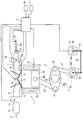
- FIG. 1 shows a system configuration of an automotive internal combustion engine 1 to which the present invention is applied.
- This internal combustion engine 1 is a spark ignition internal combustion engine with a turbocharger of a four-stroke cycle equipped with a variable compression ratio mechanism 2 using, for example, a multi-link type piston crank mechanism.
- the intake valve 4 and a pair of exhaust valves 5 are disposed, and a spark plug 6 is disposed in a central portion surrounded by the intake valves 4 and the exhaust valves 5.
- a fuel injection valve 8 for in-cylinder injection that directly injects fuel into the combustion chamber 3 is disposed below the intake port 7 that is opened and closed by the intake valve 4.
- the intake port 7 is provided with a port injection fuel injection valve 41 that injects fuel into the intake port 7.
- These in-cylinder injection fuel injection valve 8 and port injection fuel injection valve 41 are both electromagnetic or piezoelectric injection valves that are opened when a drive pulse signal is applied. An amount of fuel that is substantially proportional to the pulse width is injected.
- An electronically controlled throttle valve 19 whose opening degree is controlled by a control signal from the engine controller 9 is interposed on the upstream side of the collector portion 18a of the intake passage 18 connected to the intake port 7, and further upstream thereof.
- a turbocharger compressor 20 On the side, a turbocharger compressor 20 is arranged.
- An air flow meter 10 that detects the intake air amount is disposed upstream of the compressor 20.
- a catalyst device 13 made of a three-way catalyst is interposed in the exhaust passage 12 connected to the exhaust port 11, and an air-fuel ratio sensor 14 for detecting the air-fuel ratio is disposed upstream thereof.
- the engine controller 9 includes a crank angle sensor 15 for detecting the engine speed, a water temperature sensor 16 for detecting the coolant temperature, and an accelerator pedal operated by the driver. Detection signals of sensors such as an accelerator opening sensor 17 that detects the amount of depression of the vehicle are input. Based on these detection signals, the engine controller 9 optimally controls the fuel injection amount and injection timing by the fuel injection valves 8 and 41, the ignition timing by the spark plug 6, the opening of the throttle valve 19, and the like.
- variable compression ratio mechanism 2 uses a known multi-link type piston crank mechanism, and includes a lower link 22 rotatably supported by a crank pin 21 a of the crankshaft 21 and one end of the lower link 22.
- a control shaft 28 that supports the shaft in a swingable manner.
- the crankshaft 21 and the control shaft 28 are rotatably supported in a crankcase below the cylinder block 29 via a bearing structure (not shown).
- the control shaft 28 has an eccentric shaft portion 28a whose position changes with the rotation of the control shaft 28.
- the end portion of the control link 27 is rotatably fitted to the eccentric shaft portion 28a.
- Match. In the variable compression ratio mechanism 2 described above, the top dead center position of the piston 24 is displaced up and down with the rotation of the control shaft 28, so that the mechanical compression ratio changes.
- an electric motor 31 having a rotation center axis parallel to the crankshaft 21 is disposed below the cylinder block 29.
- a reduction gear 32 is connected so as to be arranged in series in the direction.
- the speed reducer 32 for example, a wave gear mechanism having a large speed reduction ratio is used, and the speed reducer output shaft 32 a is positioned coaxially with the output shaft (not shown) of the electric motor 31. Accordingly, the speed reducer output shaft 32a and the control shaft 28 are positioned in parallel with each other, and the first arm 33 and the control shaft 28 fixed to the speed reducer output shaft 32a are connected to each other so that both of them rotate in conjunction with each other.
- the fixed second arm 34 is connected to each other by an intermediate link 35.
- the link mechanism can also be configured to rotate in the opposite direction.
- the target compression ratio of the variable compression ratio mechanism 2 is set in the engine controller 9 based on engine operating conditions (for example, required load and engine speed), and the electric motor 31 is driven so as to realize this target compression ratio. Be controlled.
- variable compression ratio mechanism 2 is not essential and may be a fixed compression ratio internal combustion engine.
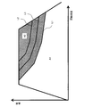
- FIG. 2 shows the operation region of the internal combustion engine 1 with the load and rotation speed of the internal combustion engine 1 as parameters, and the line indicated by the symbol L1 in the drawing shows the operation in which the target air-fuel ratio is the stoichiometric air-fuel ratio.
- the fuel supply amount is basically controlled with the stoichiometric air-fuel ratio as a target by known air-fuel ratio feedback control based on the detection signal of the air-fuel ratio sensor 14.
- the fuel supply amount is basically controlled by open loop control.
- the target air-fuel ratio becomes richer at the higher speed and higher load side.
- the in-cylinder injection fuel injection valve 8 is used as the main fuel injection valve, and the in-cylinder injection fuel injection valve 8 is driven in the entire region including both the operation areas A1 and A2.
- the port injection fuel injection valve 41 is positioned as an auxiliary fuel injection valve that operates in an auxiliary manner under specific operating conditions. That is, in the stoichiometric air-fuel ratio region A1, basically, all of the necessary fuel is injected and supplied only by the in-cylinder injection fuel injection valve 8 that is the main fuel injection valve, and the port injection fuel injection that is the sub fuel injection valve. The valve 41 is stopped.
- the line indicated by the symbol L2 in FIG. 2 indicates the operating condition corresponding to the maximum injection amount of the in-cylinder injection fuel injection valve 8 which is the main fuel injection valve.
- the entire region and a partial region on the low-speed and low-load side in the output air-fuel ratio region A2 are included. Accordingly, in these operating regions, the required fuel amount can be provided only by the in-cylinder fuel injection valve 8, but on the higher speed and higher load side than the line L2, the in-cylinder fuel injection valve 8 alone is sufficient. The amount of fuel becomes insufficient. Therefore, additional fuel injection is performed by the port injection fuel injection valve 41 which is the auxiliary fuel injection valve. In this embodiment, the port injection fuel injection valve 41 is switched between injection and stop.
- the boundary is set between the two boundary lines L1 and L2 as shown as the switching line L3. That is, the switching line L3 is on the high speed and high load side (that is, in the output air-fuel ratio region A2) from the boundary line L1 between the theoretical air-fuel ratio region A1 and the output air-fuel ratio region A2, and at the same time, fuel injection for in-cylinder injection
- the switching line L3 is on the high speed and high load side (that is, in the output air-fuel ratio region A2) from the boundary line L1 between the theoretical air-fuel ratio region A1 and the output air-fuel ratio region A2, and at the same time, fuel injection for in-cylinder injection
- it is set at a lower speed and lower load side than the maximum injection amount equivalent boundary line L2.
- an appropriate hysteresis is given at the start and stop of the operation of the port injection fuel injection valve 41.
- Both times are illustrated as a single switching line L3.
- the amount of fuel supplied by the in-cylinder fuel injection valve 8 is constant, and a shortage relative to the required fuel amount is from the port fuel injection valve 41. It is supplied by injection.
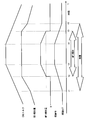
- FIG. 3 shows a time chart when the engine operating condition crosses the switching line L3 and the start and stop of the fuel injection valve 41 for port injection are performed by the driver's acceleration / deceleration operation.
- GDI means in-cylinder injection by the in-cylinder fuel injection valve 8
- MPI means port injection by the port injection fuel injection valve 41.
- the first half of this time chart shows a state where the required torque of the internal combustion engine increases due to the acceleration operation by the driver, and the engine operating condition is in the theoretical air-fuel ratio region A1 until time t1. Therefore, although the injection amount of the in-cylinder fuel injection valve 8 increases, the fuel increase rate when the stoichiometric air-fuel ratio is 1 remains at 1. At time t1, the boundary line L1 shown in FIG. 2 is crossed and the theoretical air-fuel ratio region A1 is shifted to the output air-fuel ratio region A2. Therefore, thereafter, the fuel injection rate of the in-cylinder fuel injection valve 8 increases and the fuel increase rate gradually increases. As a result of crossing the switching line L3 at time t2, fuel injection by the port injection fuel injection valve 41 is started.
- the increase in the injection amount of the in-cylinder fuel injection valve 8 stops.
- the port injection fuel injection valve 41 starts fuel injection with the smallest injection amount.
- the fuel injection valve 41 has an inherent minimum fuel injection amount as described above, at least the minimum fuel injection amount. The fuel supply by is performed immediately after the start. Therefore, when the fuel injected from the port injection fuel injection valve 41 to the intake port 7 reaches the combustion chamber 3, the total amount of fuel increases stepwise.
- the injection / stop switching of the port injection fuel injection valve 41 is performed during the period in which the fuel increase is performed by the in-cylinder injection fuel injection valve 8 which is the main fuel injection valve. Is executed. Thereby, the sensitivity of the torque with respect to the step increase / decrease of the fuel amount corresponding to at least the minimum fuel injection amount is lowered, and the torque step feeling can be suppressed.
- the in-cylinder injection fuel injection valve 8 is the main fuel injection valve, and the fuel amount is compensated by the port injection fuel injection valve 41 in the high speed and high load region where the injection amount becomes insufficient. Therefore, the in-cylinder injection fuel injection valve 8 having a relatively small capacity can be used for a wide change in the air amount (and consequently the required fuel amount) due to supercharging. It becomes easy. Further, it is possible to use a port injection fuel injection valve 41 having a relatively small minimum fuel injection amount.
- the operation with the stoichiometric air-fuel ratio is performed only by the in-cylinder injection fuel injection valve 8, and the port injection fuel injection valve 41 is stopped.
- the trigger signal for requesting the operation of the port injection fuel injection valve 41 is turned on.
- the injection amount of the in-cylinder injection fuel injection valve 8 is increased without immediately switching, and the air-fuel ratio is increased. Is rich.
- the ignition timing is retarded in accordance with the fuel increase, and the increase in torque due to enrichment is suppressed.
- execution of switching that is, injection of the port injection fuel injection valve 41 is started.
- the injection amount of the in-cylinder injection fuel injection valve 8 is reduced, and the in-cylinder injection fuel injection valve 8 is maintained at an appropriate share ratio during the period of time t4 to t5.
- the injection amounts is feedback-controlled based on the detection signal of the air-fuel ratio sensor 14 so that the theoretical air-fuel ratio is maintained by the fuel injection of both the fuel injection valve 41 and the port injection fuel injection valve 41. It should be noted that the theoretical air-fuel ratio may be maintained by open loop control during the time t4 to t5.
- the ignition timing is gradually retarded so as to correspond to the fuel increase (riching) during the time t1 to t2, but during the time t2 to t3 when the air-fuel ratio becomes richer than the predetermined level AF1, the total fuel is Since there is almost no increase in torque accompanying the increase in amount, the ignition timing is constant. Then, during the time t3 to t4 when the air-fuel ratio is closer to the stoichiometric air-fuel ratio than the predetermined level AF1, the torque decreases as the fuel increase rate decreases. Advance the ignition timing that was being used.
- the ignition timing corresponding to the total fuel amount corresponding to the stoichiometric air-fuel ratio is restored, but in the in-cylinder injection by the in-cylinder injection fuel injection valve 8 and the port injection by the port injection fuel injection valve 41. Since the optimal ignition timing is different, it is slightly retarded from the ignition timing ADV0 before time t1.
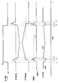
- the process of stopping the injection of the port injection fuel injection valve 41 and returning to the operation with only the in-cylinder injection fuel injection valve 8 is shown.
- the injection request of the port injection fuel injection valve 41 is shown.
- the signal trigger signal
- the fuel increase by the in-cylinder fuel injection valve 8 is performed prior to actual switching, and the air-fuel ratio is enriched.
- the fuel is increased so that the air / fuel ratio (predetermined level AF1) is higher than the stoichiometric air / fuel ratio with at least the injection amount of the in-cylinder fuel injection valve 8 alone.
- the ignition timing is retarded so as to offset the increase in torque accompanying the enrichment of the air-fuel ratio.
- the ignition timing is constant during the time t6 to t7 for the same reason as the time t2 to t3 described above. Then, at time t7 when the air-fuel ratio becomes rich to the above level, the port injection fuel injection valve 41 is stopped. Even when the total fuel amount is decreased stepwise as the port injection fuel injection valve 41 is stopped, the air-fuel ratio is higher than the stoichiometric air-fuel ratio (rich state of a predetermined level AF1 or more with less influence on torque). Therefore, the torque step due to the decrease in the total fuel amount is relatively small. After the switching (stop of the port injection fuel injection valve 41), the injection amount of the in-cylinder injection fuel injection valve 8 gradually decreases, and the ignition timing returns to the normal ignition timing accordingly. After the time t8, the operation with the stoichiometric air-fuel ratio is performed only by the in-cylinder fuel injection valve 8.
- the fuel injection valves 8 and 41 can be switched while suppressing the torque step.
- the increase / decrease of the injection amount by the in-cylinder fuel injection valve 8 during the time t1 to t4 and during the time t5 to t8 can be gradually performed so as not to cause a torque step feeling.
- the torque adjustment by the ignition timing retard is not always essential.
- the fuel injection from only the in-cylinder injection fuel injection valve 8 is switched to the fuel injection from both the in-cylinder injection fuel injection valve 8 and the port injection fuel injection valve 41.
Landscapes
- Engineering & Computer Science (AREA)
- Chemical & Material Sciences (AREA)
- Combustion & Propulsion (AREA)
- Mechanical Engineering (AREA)
- General Engineering & Computer Science (AREA)
- Electrical Control Of Air Or Fuel Supplied To Internal-Combustion Engine (AREA)
- Electrical Control Of Ignition Timing (AREA)
- Fuel-Injection Apparatus (AREA)
- Combined Controls Of Internal Combustion Engines (AREA)
Abstract
Description
Claims (6)
- 吸気ポートに燃料を噴射するポート噴射用燃料噴射弁と、燃焼室に燃料を噴射する筒内噴射用燃料噴射弁と、を備え、一方の燃料噴射弁を主燃料噴射弁とし、他方を特定の機関運転条件で補助的に動作する副燃料噴射弁とし、機関運転条件に応じて上記副燃料噴射弁の噴射・停止の切換を行う内燃機関の制御装置において、
上記副燃料噴射弁の噴射・停止の切換を、上記主燃料噴射弁の燃料噴射量による空燃比が理論空燃比よりも濃い条件下で行う、内燃機関の制御装置。 - 内燃機関の目標空燃比が理論空燃比よりも濃い出力空燃比である運転領域と目標空燃比が理論空燃比である運転領域との境界よりも高速高負荷側において上記副燃料噴射弁の噴射・停止の切換を行う、請求項1に記載の内燃機関の制御装置。
- 上記副燃料噴射弁の噴射・停止の切換が要求されたときに、上記主燃料噴射弁の燃料噴射量の増量によって空燃比を理論空燃比よりも濃くする、請求項1に記載の内燃機関の制御装置。
- 上記の燃料噴射量の増量とともに点火時期のリタードを行う、請求項3に記載の内燃機関の制御装置。
- 上記主燃料噴射弁は、運転領域の全域で燃料噴射を行う、請求項1~4のいずれかに記載の内燃機関の制御装置。
- 吸気ポートに燃料を噴射するポート噴射用燃料噴射弁と、燃焼室に燃料を噴射する筒内噴射用燃料噴射弁と、を備え、一方の燃料噴射弁を主燃料噴射弁とし、他方を特定の機関運転条件で補助的に動作する副燃料噴射弁とし、機関運転条件に応じて上記副燃料噴射弁の噴射・停止の切換を行う内燃機関の制御方法において、
上記副燃料噴射弁の噴射・停止の切換を、上記主燃料噴射弁の燃料噴射量による空燃比が理論空燃比よりも濃い条件下で行う、内燃機関の制御方法。
Priority Applications (7)
| Application Number | Priority Date | Filing Date | Title |
|---|---|---|---|
| US14/774,770 US9874172B2 (en) | 2013-03-21 | 2014-01-10 | Control device and control method for internal combustion engines |
| BR112015024238-3A BR112015024238B1 (pt) | 2013-03-21 | 2014-01-10 | Dispositivo de controle e método de controle para motores de combustão interna |
| CN201480017199.7A CN105051355B (zh) | 2013-03-21 | 2014-01-10 | 内燃机的控制装置以及控制方法 |
| RU2015138459A RU2628009C2 (ru) | 2013-03-21 | 2014-01-10 | Устройство управления и способ управления для двигателей внутреннего сгорания |
| JP2015506618A JP6011714B2 (ja) | 2013-03-21 | 2014-01-10 | 内燃機関の制御装置および制御方法 |
| MX2015013098A MX343530B (es) | 2013-03-21 | 2014-01-10 | Dispositivo de control y metodo de control para motores de combustion interna. |
| EP14767370.1A EP2977597B1 (en) | 2013-03-21 | 2014-01-10 | Control device and control method for internal combustion engines |
Applications Claiming Priority (2)
| Application Number | Priority Date | Filing Date | Title |
|---|---|---|---|
| JP2013-057493 | 2013-03-21 | ||
| JP2013057493 | 2013-03-21 |
Publications (1)
| Publication Number | Publication Date |
|---|---|
| WO2014148067A1 true WO2014148067A1 (ja) | 2014-09-25 |
Family
ID=51579764
Family Applications (1)
| Application Number | Title | Priority Date | Filing Date |
|---|---|---|---|
| PCT/JP2014/050289 Ceased WO2014148067A1 (ja) | 2013-03-21 | 2014-01-10 | 内燃機関の制御装置および制御方法 |
Country Status (8)
| Country | Link |
|---|---|
| US (1) | US9874172B2 (ja) |
| EP (1) | EP2977597B1 (ja) |
| JP (1) | JP6011714B2 (ja) |
| CN (1) | CN105051355B (ja) |
| BR (1) | BR112015024238B1 (ja) |
| MX (1) | MX343530B (ja) |
| RU (1) | RU2628009C2 (ja) |
| WO (1) | WO2014148067A1 (ja) |
Cited By (2)
| Publication number | Priority date | Publication date | Assignee | Title |
|---|---|---|---|---|
| CN106246386A (zh) * | 2015-06-11 | 2016-12-21 | 福特环球技术公司 | 减轻进气道喷射退化的方法和系统 |
| JP2019199822A (ja) * | 2018-05-15 | 2019-11-21 | マツダ株式会社 | エンジンの制御装置 |
Families Citing this family (7)
| Publication number | Priority date | Publication date | Assignee | Title |
|---|---|---|---|---|
| JP6111899B2 (ja) * | 2013-06-28 | 2017-04-12 | 三菱自動車工業株式会社 | エンジンの制御装置 |
| US10041433B2 (en) * | 2015-11-06 | 2018-08-07 | Ford Global Technologies, Llc | Methods and systems for dual fuel injection |
| DE102016203641A1 (de) * | 2016-03-07 | 2017-09-07 | Robert Bosch Gmbh | Verfahren zum Betreiben einer Brennkraftmaschine |
| JP6520910B2 (ja) * | 2016-12-26 | 2019-05-29 | トヨタ自動車株式会社 | 内燃機関の制御装置 |
| JP6835217B2 (ja) * | 2017-05-24 | 2021-02-24 | 日産自動車株式会社 | 内燃機関の制御方法及び制御装置 |
| JP6866827B2 (ja) * | 2017-11-15 | 2021-04-28 | トヨタ自動車株式会社 | 内燃機関の制御装置 |
| CN113853479B (zh) * | 2019-05-24 | 2023-04-14 | 日产自动车株式会社 | 内燃机的控制方法以及控制装置 |
Citations (7)
| Publication number | Priority date | Publication date | Assignee | Title |
|---|---|---|---|---|
| JPH06193496A (ja) * | 1992-12-28 | 1994-07-12 | Mazda Motor Corp | エンジンの制御装置 |
| JPH11351011A (ja) * | 1998-06-08 | 1999-12-21 | Unisia Jecs Corp | 内燃機関の燃料噴射制御装置 |
| JP2005220887A (ja) * | 2004-02-09 | 2005-08-18 | Toyota Motor Corp | 内燃機関の制御装置 |
| JP2006057594A (ja) | 2004-08-23 | 2006-03-02 | Toyota Motor Corp | 内燃機関の点火時期制御方法 |
| JP2006336621A (ja) * | 2005-06-06 | 2006-12-14 | Toyota Motor Corp | 内燃機関の制御装置 |
| JP2009191662A (ja) * | 2008-02-12 | 2009-08-27 | Honda Motor Co Ltd | 内燃機関の燃料噴射制御装置 |
| JP2012202373A (ja) * | 2011-03-28 | 2012-10-22 | Toyota Motor Corp | 気筒間空燃比ばらつき異常検出装置 |
Family Cites Families (13)
| Publication number | Priority date | Publication date | Assignee | Title |
|---|---|---|---|---|
| JPS63248938A (ja) * | 1987-04-06 | 1988-10-17 | Mazda Motor Corp | エンジンの成層燃焼制御装置 |
| JPH05280404A (ja) * | 1992-03-31 | 1993-10-26 | Mazda Motor Corp | エンジンの燃料噴射装置 |
| US5803048A (en) * | 1994-04-08 | 1998-09-08 | Honda Giken Kogyo Kabushiki Kaisha | System and method for controlling air-fuel ratio in internal combustion engine |
| JP3152106B2 (ja) * | 1995-05-16 | 2001-04-03 | 三菱自動車工業株式会社 | 筒内噴射型火花点火式内燃エンジンの制御装置 |
| SE522177C2 (sv) * | 1996-08-27 | 2004-01-20 | Mitsubishi Motors Corp | Styranordning för en förbränningsmotor med cylinderinsprutning och gnisttändning |
| JP3060960B2 (ja) * | 1996-09-25 | 2000-07-10 | トヨタ自動車株式会社 | 筒内噴射内燃機関の燃料噴射制御装置 |
| JP4349344B2 (ja) * | 2005-08-23 | 2009-10-21 | トヨタ自動車株式会社 | エンジンの制御装置 |
| US7426918B2 (en) * | 2006-03-20 | 2008-09-23 | Ford Global Technologies, Llc | Engine having multiple injector locations |
| RU65974U1 (ru) * | 2007-04-05 | 2007-08-27 | Московский Государственный Индустриальный Университет (Мгиу) | Двигатель внутреннего сгорания |
| JP5047011B2 (ja) * | 2008-03-12 | 2012-10-10 | 本田技研工業株式会社 | 内燃機関の燃料噴射制御装置 |
| JP2009228447A (ja) * | 2008-03-19 | 2009-10-08 | Toyota Motor Corp | 内燃機関の燃料噴射制御装置 |
| JP5418665B2 (ja) * | 2010-03-19 | 2014-02-19 | トヨタ自動車株式会社 | 内燃機関の制御装置 |
| GB2491149A (en) * | 2011-05-24 | 2012-11-28 | Gm Global Tech Operations Inc | Regenerating a lean NOx trap |
-
2014
- 2014-01-10 EP EP14767370.1A patent/EP2977597B1/en not_active Not-in-force
- 2014-01-10 JP JP2015506618A patent/JP6011714B2/ja not_active Expired - Fee Related
- 2014-01-10 WO PCT/JP2014/050289 patent/WO2014148067A1/ja not_active Ceased
- 2014-01-10 CN CN201480017199.7A patent/CN105051355B/zh not_active Expired - Fee Related
- 2014-01-10 US US14/774,770 patent/US9874172B2/en not_active Expired - Fee Related
- 2014-01-10 MX MX2015013098A patent/MX343530B/es active IP Right Grant
- 2014-01-10 BR BR112015024238-3A patent/BR112015024238B1/pt not_active IP Right Cessation
- 2014-01-10 RU RU2015138459A patent/RU2628009C2/ru active
Patent Citations (7)
| Publication number | Priority date | Publication date | Assignee | Title |
|---|---|---|---|---|
| JPH06193496A (ja) * | 1992-12-28 | 1994-07-12 | Mazda Motor Corp | エンジンの制御装置 |
| JPH11351011A (ja) * | 1998-06-08 | 1999-12-21 | Unisia Jecs Corp | 内燃機関の燃料噴射制御装置 |
| JP2005220887A (ja) * | 2004-02-09 | 2005-08-18 | Toyota Motor Corp | 内燃機関の制御装置 |
| JP2006057594A (ja) | 2004-08-23 | 2006-03-02 | Toyota Motor Corp | 内燃機関の点火時期制御方法 |
| JP2006336621A (ja) * | 2005-06-06 | 2006-12-14 | Toyota Motor Corp | 内燃機関の制御装置 |
| JP2009191662A (ja) * | 2008-02-12 | 2009-08-27 | Honda Motor Co Ltd | 内燃機関の燃料噴射制御装置 |
| JP2012202373A (ja) * | 2011-03-28 | 2012-10-22 | Toyota Motor Corp | 気筒間空燃比ばらつき異常検出装置 |
Non-Patent Citations (1)
| Title |
|---|
| See also references of EP2977597A4 |
Cited By (2)
| Publication number | Priority date | Publication date | Assignee | Title |
|---|---|---|---|---|
| CN106246386A (zh) * | 2015-06-11 | 2016-12-21 | 福特环球技术公司 | 减轻进气道喷射退化的方法和系统 |
| JP2019199822A (ja) * | 2018-05-15 | 2019-11-21 | マツダ株式会社 | エンジンの制御装置 |
Also Published As
| Publication number | Publication date |
|---|---|
| MX2015013098A (es) | 2016-01-22 |
| BR112015024238A2 (pt) | 2017-07-18 |
| EP2977597B1 (en) | 2017-10-25 |
| US20160032860A1 (en) | 2016-02-04 |
| MX343530B (es) | 2016-11-09 |
| EP2977597A4 (en) | 2016-04-06 |
| EP2977597A1 (en) | 2016-01-27 |
| US9874172B2 (en) | 2018-01-23 |
| BR112015024238B1 (pt) | 2021-11-30 |
| RU2628009C2 (ru) | 2017-08-14 |
| CN105051355B (zh) | 2018-01-02 |
| JPWO2014148067A1 (ja) | 2017-02-16 |
| JP6011714B2 (ja) | 2016-10-19 |
| CN105051355A (zh) | 2015-11-11 |
| RU2015138459A (ru) | 2017-04-26 |
Similar Documents
| Publication | Publication Date | Title |
|---|---|---|
| JP6011714B2 (ja) | 内燃機関の制御装置および制御方法 | |
| JP3603398B2 (ja) | 内燃機関の制御装置 | |
| US7278383B2 (en) | Internal combustion engine with variable compression ratio and valve characteristics | |
| WO2014129225A1 (ja) | 内燃機関の制御装置および制御方法 | |
| US10260440B2 (en) | Fuel injection control device and control method for internal combustion engine | |
| JP6350304B2 (ja) | リーンバーンエンジン | |
| JP6326728B2 (ja) | 内燃機関の制御装置および制御方法 | |
| JP2014224494A (ja) | 内燃機関の制御装置および制御方法 | |
| JP6515710B2 (ja) | 内燃機関の制御装置 | |
| JP2015017518A (ja) | 内燃機関の制御装置および制御方法 | |
| JP6371040B2 (ja) | 内燃機関の制御装置および制御方法 | |
| JP6734633B2 (ja) | 内燃機関の制御装置 | |
| JP2011038477A (ja) | エンジンの制御装置 | |
| JP5195438B2 (ja) | ハイブリッド車両のエンジン停止制御装置 | |
| JP2010229911A (ja) | 可変動弁機構の制御装置 | |
| JP2010216396A (ja) | 吸気量制御装置 | |
| JP2011247113A (ja) | 内燃機関の吸入空気量制御方法 | |
| JP6443244B2 (ja) | 可変圧縮比内燃機関の制御装置 | |
| JP6232758B2 (ja) | 内燃機関の制御装置および制御方法 | |
| JP2007127100A (ja) | 内燃機関の制御装置 | |
| JP2004036582A (ja) | 内燃機関の制御方法 | |
| JP2014224462A (ja) | 内燃機関の制御装置および制御方法 | |
| JP2008196378A (ja) | ガソリンエンジンの制御方法 | |
| JP2009138544A (ja) | 内燃機関の制御装置 | |
| JP2013144945A (ja) | 内燃機関の制御装置 |
Legal Events
| Date | Code | Title | Description |
|---|---|---|---|
| WWE | Wipo information: entry into national phase |
Ref document number: 201480017199.7 Country of ref document: CN |
|
| 121 | Ep: the epo has been informed by wipo that ep was designated in this application |
Ref document number: 14767370 Country of ref document: EP Kind code of ref document: A1 |
|
| ENP | Entry into the national phase |
Ref document number: 2015506618 Country of ref document: JP Kind code of ref document: A |
|
| WWE | Wipo information: entry into national phase |
Ref document number: 14774770 Country of ref document: US |
|
| WWE | Wipo information: entry into national phase |
Ref document number: MX/A/2015/013098 Country of ref document: MX |
|
| NENP | Non-entry into the national phase |
Ref country code: DE |
|
| REEP | Request for entry into the european phase |
Ref document number: 2014767370 Country of ref document: EP |
|
| WWE | Wipo information: entry into national phase |
Ref document number: 2014767370 Country of ref document: EP |
|
| ENP | Entry into the national phase |
Ref document number: 2015138459 Country of ref document: RU Kind code of ref document: A |
|
| REG | Reference to national code |
Ref country code: BR Ref legal event code: B01A Ref document number: 112015024238 Country of ref document: BR |
|
| ENP | Entry into the national phase |
Ref document number: 112015024238 Country of ref document: BR Kind code of ref document: A2 Effective date: 20150921 |