WO2014148331A1 - 内燃機関のピストン - Google Patents
内燃機関のピストン Download PDFInfo
- Publication number
- WO2014148331A1 WO2014148331A1 PCT/JP2014/056468 JP2014056468W WO2014148331A1 WO 2014148331 A1 WO2014148331 A1 WO 2014148331A1 JP 2014056468 W JP2014056468 W JP 2014056468W WO 2014148331 A1 WO2014148331 A1 WO 2014148331A1
- Authority
- WO
- WIPO (PCT)
- Prior art keywords
- piston
- oil gallery
- combustion chamber
- internal
- top surface
- Prior art date
- Legal status (The legal status is an assumption and is not a legal conclusion. Google has not performed a legal analysis and makes no representation as to the accuracy of the status listed.)
- Ceased
Links
Images


Classifications
-
- F—MECHANICAL ENGINEERING; LIGHTING; HEATING; WEAPONS; BLASTING
- F02—COMBUSTION ENGINES; HOT-GAS OR COMBUSTION-PRODUCT ENGINE PLANTS
- F02F—CYLINDERS, PISTONS OR CASINGS, FOR COMBUSTION ENGINES; ARRANGEMENTS OF SEALINGS IN COMBUSTION ENGINES
- F02F3/00—Pistons
- F02F3/16—Pistons having cooling means
- F02F3/20—Pistons having cooling means the means being a fluid flowing through or along piston
- F02F3/22—Pistons having cooling means the means being a fluid flowing through or along piston the fluid being liquid
Definitions
- One aspect of the present invention relates to a piston for an internal combustion engine.
- Japanese Patent Application Laid-Open No. 2011-17263 is known as a technical document related to a piston of an internal combustion engine.
- This publication discloses a piston having a combustion chamber provided on the top surface of the piston and an oil gallery formed so as to surround the combustion chamber.
- an object of the present invention is to provide a piston of an internal combustion engine that can suppress deformation of the piston due to a temperature difference.
- one aspect of the present invention is a piston having a combustion chamber provided on a piston top surface and an oil gallery formed so as to surround the combustion chamber, and the sliding side surface of the piston To the oil gallery is characterized in that the piston skirt side is thicker than the piston top surface side.
- the thickness from the sliding side surface of the piston to the oil gallery is formed so that the piston skirt side is thicker than the piston top surface side.
- the engine oil sufficiently cools the piston top surface, which becomes hot during combustion, while avoiding excessive cooling of the piston skirt side where the temperature rise due to combustion is small. Piston deformation can be suppressed by reducing the temperature difference.
- the oil gallery may have an external inclined surface that approaches the piston central axis from the piston top surface side toward the piston skirt side.
- the inner side surface of the oil gallery may be formed along the side wall of the combustion chamber.
- the side wall of the combustion chamber has a lip portion that protrudes to the inside of the combustion chamber, and the internal side surface of the oil gallery is an internal expansion projecting toward the lip portion. It may have a surface.
- the piston of the internal combustion engine according to one aspect of the present invention can suppress the deformation of the piston due to the temperature difference.
- a piston 1 according to the first embodiment is provided in an internal combustion engine such as a diesel engine of a vehicle, and reciprocates in the extending direction of a central axis (piston central axis) C inside a cylinder S. Exercise.
- the piston 1 is connected to the crankshaft of the internal combustion engine via a connecting rod, and the reciprocating energy of the piston 1 is converted to the rotational energy of the crankshaft via the connecting rod. Illustration of the connecting rod and the crankshaft is omitted.
- the piston 1 includes a piston top surface 2, a sliding side surface 3, and a piston skirt 4.
- the piston top surface 2 side of the piston 1 is used as an upper side
- the piston skirt 4 side is used as a lower side for description.
- the piston top surface 2 is an upper end surface of the piston that forms a space E for burning in the cylinder S.
- the piston 1 has a combustion chamber 5.
- the sliding side surface 3 is a piston side surface that slides with the inner surface of the cylinder S.
- the sliding side surface 3 is formed with piston ring grooves 3a to 3c into which the piston rings 8A to 8C are fitted, respectively.
- first piston ring groove 3a In the first piston ring groove 3a, the first piston ring 8A located closest to the piston top surface 2 is disposed.
- a third piston ring 8C located closest to the piston skirt 4 is disposed.
- the piston skirt 4 is a skirt-like portion formed so as to extend downward along the sliding side surface 3. A small end portion of the connecting rod is disposed in the internal space 7 of the piston skirt 4.
- the combustion chamber 5 is a part of a space E in which fuel mixed with air burns, and is a space formed on the piston 1 side.
- the combustion chamber 5 has a bottom surface 5a and a side wall 5b.
- the bottom surface 5a is formed so as to be inclined upward as it approaches the center (center axis C).
- the combustion chamber 5 is a reentrant combustion chamber in which the side wall 5b is inclined inward (center axis C side).
- a lip portion Lp is formed which is the portion of the sidewall 5 b that protrudes most inside.
- the combustion chamber 5 is not limited to the reentrant type, and may be a toroidal type combustion chamber in which the side wall 5b is vertically formed so as to follow the central axis C.
- the side wall 5b is vertical and the bottom surface 5a is also formed in a plane. It may be a bathtub-type combustion chamber.
- the piston 1 has an oil gallery 6 formed in an annular shape so as to surround the combustion chamber 5 (central axis C).
- the oil gallery 6 is a cavity formed inside the piston 1 and cools the piston 1 by flowing engine oil through an oil jet hole (not shown).
- the cross-sectional shape (the cross-sectional shape shown in FIG. 1) along the central axis C has a substantially oval shape.
- the oil gallery 6 has an external inclined surface 6a, an internal enlarged surface 6b, and an internal inclined surface 6c.
- the external inclined surface 6a is an external side surface of the oil gallery 6 (a side surface opposite to the combustion chamber 5).
- the external inclined surface 6a is formed as a plane that approaches the central axis C as it goes from the piston top surface 2 side to the piston skirt 4 side. That is, the external inclined surface 6a is inclined so as to be separated from the sliding side surface 3 toward the lower side.
- the external inclined surface 6 a is formed on the sliding side surface 3 side (the side opposite to the central axis C) of the piston 1 in the oil gallery 6.
- the external inclined surface 6a may be a curved surface, and may include both a flat surface and a curved surface.
- the inner enlarged surface 6b and the inner inclined surface 6c form an inner side surface (side surface on the combustion chamber 5 side) of the oil gallery 6 and are formed along the side wall 5b of the combustion chamber 5. That is, the inner side surface of the oil gallery 6 is formed along the side wall 5 b of the combustion chamber 5.
- the internal enlarged surface 6b is formed on the upper side of the internal side surface of the oil gallery 6 (on the piston top surface 2 side).
- the internal enlarged surface 6b is a part that enlarges the oil gallery 6 toward the combustion chamber 5 side (center axis C side). That is, the internal enlarged surface 6b is formed to protrude toward the combustion chamber 5 side.
- the internal enlarged surface 6 b is formed so as to protrude toward the lip portion Lp that protrudes most toward the central axis C side in the side wall 5 b of the combustion chamber 5.
- the internal enlarged surface 6b is formed so that the wall thickness between the internal side surface of the oil gallery 6 and the side wall 5b of the combustion chamber 5 approaches evenly compared with the case where there is no internal enlarged surface 6b.
- the wall thickness between the inner side surface of the oil gallery 6 and the side wall 5b of the combustion chamber 5 has a sufficient thickness to ensure strength.
- the inner inclined surface 6c is a flat surface formed on the lower side (piston skirt 4 side) of the inner side surface of the oil gallery 6 and inclined substantially parallel to the outer inclined surface 6a.
- the internal inclined surface 6 c is formed so as to be inclined along the side wall 5 b of the combustion chamber 5.
- the length in the extending direction of the central axis C is L
- the upper effective thickness of the thickness from the sliding side surface 3 of the piston 1 to the oil gallery 6 in the direction orthogonal to the central axis C is A
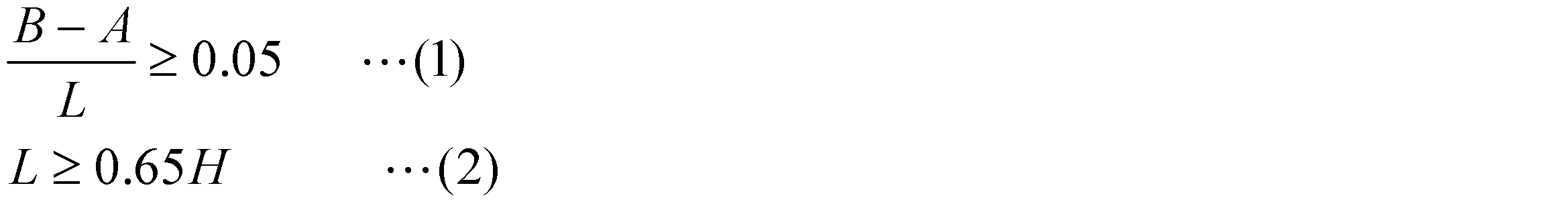
- the oil gallery 6 satisfies the following expressions (1) and (2).
- H is the depth of the combustion chamber 5 shown in FIG. 1 (distance from the piston top surface 2 to the bottom surface of the combustion chamber 5).
- the upper effective wall thickness A in this embodiment means the thinnest wall thickness from the sliding side surface 3 of the piston 1 to the piston top surface 2 side of the oil gallery 6.
- the lower effective thickness B in the present embodiment is an imaginary straight line V1 (same as the lower dimension line indicating L in FIG. 1) passing through the lower end of the oil gallery 6 and perpendicular to the central axis C in the cross section of FIG. This means the thickness from the sliding side surface 3 of the piston 1 to the intersection W, where W is the intersection with the extension line V2 along the external inclined surface 6a.
- FIG. 2 is a graph showing an example of the temperature difference of the piston 1 with respect to (BA) / L described above.
- the vertical axis in FIG. 2 is the temperature difference between the vicinity of the first piston ring 8A on the piston top surface 2 side and the vicinity of the third piston ring 8C on the piston skirt 4 side.
- the horizontal axis in FIG. 2 is (BA) / L.
- FIG. 2 is an example showing a temperature difference of the piston 1 with respect to (BA) / L, and the present invention is not limited to the above-described content.
- the thickness from the sliding side surface 3 to the oil gallery 6 is formed so that the piston skirt 4 side is thicker than the piston top surface 2 side. While the piston top surface 2 side that becomes hot due to combustion is sufficiently cooled by the oil flowing through the oil gallery 6, it is avoided that the piston skirt 4 side where the temperature rise due to combustion is small is excessively cooled, and the piston top surface 2 side And the deformation of the piston 1 can be suppressed by reducing the temperature difference between the piston skirt 4 side and the piston skirt 4 side.
- the piston 1 it is possible to avoid the piston ring grooves 3a to 3c from being deformed due to the temperature difference, thereby preventing the seizure and the sealing performance from being deteriorated due to poor behavior of the piston rings 8A to 8C.
- the amount of blow-by can be reduced by improving reliability and sealing performance of ⁇ 8C.
- the shape of the oil gallery 6 is not the piston shape.
- the thickness from the sliding side surface 3 of the piston 1 to the oil gallery 6 can be increased toward the lower side, and the piston skirt 4 side can be prevented from being excessively cooled by the oil flowing through the oil gallery 6.
- the distance H L from the piston top surface 2 to the lower end of the oil gallery 6 is such that the piston top surface 2 and the second piston ring groove 3b (that is, the second piston ring). It is longer than the distance Hr to 8B).
- the oil gallery 6 is formed so as to extend vertically from the upper side of the first piston ring groove 3a to the vicinity of the third piston ring groove 3c beyond the second piston ring groove 3b. Yes. Thereby, also in the 2nd piston ring groove
- the lip portion Lp of the combustion chamber 5 can be appropriately cooled. That is, in the reentrant combustion chamber 5, by providing the lip portion Lp, the flow of air and the fuel mixed with air is appropriately tuned, and the combustion efficiency in the combustion chamber 5 can be increased. However, the lip portion Lp that protrudes inward from the side wall 5b of the combustion chamber 5 is liable to be adversely affected by heat concentration. Therefore, in the piston 1 according to the present embodiment, the oil gallery 6 has the internal enlarged surface 6b that is recessed toward the lip portion Lp, so that the lip portion Lp can be appropriately cooled by the oil flowing through the oil gallery 6.
- the inner side surface (the inner enlarged surface 6b and the inner inclined surface 6c) of the oil gallery 6 is formed along the side wall 5b of the combustion chamber 5, so that the side wall 5b of the combustion chamber 5 and the oil gallery It is possible to make the thickness of the piston 1 between the inner side surfaces of the six parts evenly close. Thereby, compared with the case where the wall thickness between the internal side surface of the oil gallery 6 and the side wall 5b of the combustion chamber 5 is not uniform, it is avoided that the temperature distribution of the side wall 5b becomes nonuniform by cooling of oil. it can.
- the temperature distribution of the side wall 5b becomes non-uniform so that the temperature distribution of the air in the combustion chamber 5 becomes non-uniform and the temperature distribution of the piston 1 becomes non-uniform.
- the deformation of the piston 1 due to the difference can be suppressed, and the combustion efficiency in the combustion chamber 5 can be suppressed from decreasing.
- the second to fourth embodiments will be described below with reference to FIGS.
- the pistons 10, 20, and 30 according to the second to fourth embodiments are different from the piston 1 according to the first embodiment only in the shape of the oil gallery.
- symbol is attached
- the oil gallery 11 of the piston 10 according to the second embodiment shown in FIG. 3 has an oval cross-sectional shape (a cross-sectional shape along the central axis C).
- the oil gallery 11 has the external inclined surface 11a as in the first embodiment, but does not have a portion like the internal enlarged surface 6b.
- the inner side surface of the oil gallery 11 forms an inclined surface along the outer inclined surface 11a.
- the oil gallery 11 also has a length L in the extending direction of the central axis C, an upper effective wall thickness A and a lower effective wall thickness B from the sliding side surface 3 of the piston 1 to the oil gallery 6. As in the first embodiment, the above-described expressions (1) and (2) are satisfied.
- the distance H L from the piston top surface 2 to the lower end of the oil gallery 11 is longer than the distance Hr from the piston top surface 2 to the second piston ring groove 3b (that is, the second piston ring 8B).
- the length L in the extending direction of the central axis C, the upper effective wall thickness A, and the lower effective wall thickness B satisfy the above-mentioned formulas (1) and (2) and the point where the distance HL is longer than the distance Hr. The same applies to the third and fourth embodiments.
- the oil gallery 21 of the piston 20 according to the third embodiment has a dogleg shape with the lower side of an ellipse extending in the extending direction of the central axis C toward the central axis C. It has a cross-sectional shape (a cross-sectional shape along the central axis C) that is bent.
- the oil gallery 21 has an upper external vertical surface 21a and a lower external inclined surface 21b.
- the external vertical surface 21 a and the external inclined surface 21 b form the external side surface of the oil gallery 21.
- the external vertical surface 21 a and the external inclined surface 21 b are formed on the sliding side surface 3 side (the side opposite to the central axis C) of the oil gallery 21.
- the external vertical surface 21a is a plane that extends in the extending direction of the central axis C
- the external inclined surface 21b is a plane that is inclined so as to approach the central axis C as it goes downward.
- the external vertical surface 21a and the external inclined surface 21b may be curved surfaces, and may include a flat surface and a curved surface.
- the oil gallery 21 has an upper internal vertical surface 21c and a lower internal inclined surface 21d.
- the internal vertical surface 21 c and the internal inclined surface 21 d form the internal side surface of the oil gallery 21.
- the piston 30 according to the fourth embodiment shown in FIG. 5 will be described.
- the upper side of the ellipse extending in the extending direction of the central axis C is the sliding side surface 3 side (opposite of the central axis C).
- the cross-sectional shape (cross-sectional shape along the central axis C) is bent in a dogleg shape.
- the oil gallery 31 has an upper external inclined surface 31a and a lower external vertical surface 31b.
- the external inclined surface 31 a and the external vertical surface 31 b are formed on the sliding side surface 3 side (the side opposite to the central axis C) of the oil gallery 31.
- the external inclined surface 31a is a flat surface that is inclined so as to approach the central axis C as it goes downward
- the external vertical surface 31b is a flat surface that extends in the extending direction of the central axis C.
- the external inclined surface 31a and the external vertical surface 31b may be curved surfaces, and may include a flat surface and a curved surface.
- the wall thickness from the sliding side surface 3 to the oil galleries 11, 21, 31 is closer to the piston skirt 4 side than the piston top surface 2 side. It is formed thick, and the same effect as the piston 1 according to the first embodiment can be obtained.
- the piston 40 according to the fifth embodiment differs from the piston 20 according to the third embodiment only in the shape of the combustion chamber.
- the combustion chamber 41 of the piston 40 according to the fifth embodiment shown in FIG. 6 is a so-called bathtub type combustion chamber.
- the combustion chamber 41 includes, for example, a bottom surface (a bottom surface substantially parallel to the piston top surface 2) 41a perpendicular to the center axis C and a side wall (a side wall substantially perpendicular to the piston top surface 2) extending along the center axis C. 41b.
- the upper end of the opening of the combustion chamber 41 formed on the piston top surface 2 is a lip portion Lp.
- the internal vertical surface 21c of the oil gallery 21 is formed along the side wall 41b of the combustion chamber 41. Further, the inner inclined surface 21d of the oil gallery 21 is inclined so as to follow the connection portion between the bottom surface 41a of the combustion chamber 41 and the side wall 41b.
- the internal vertical surface 21c of the oil gallery 21 is formed along the side wall 41b of the combustion chamber 41, and therefore the side wall 41b of the combustion chamber 41 and the oil gallery 21 are formed. It is possible to make the thickness of the piston 40 between the inner side surfaces of the first and second inner surfaces uniform. Thereby, compared with the case where the wall thickness between the internal side surface of the oil gallery 21 and the side wall 41b of the combustion chamber 41 is not uniform, it is avoided that the temperature distribution of the side wall 41b becomes nonuniform by cooling of oil. it can.
- the temperature distribution of the side wall 41b becomes non-uniform so that the temperature distribution of the air in the combustion chamber 41 becomes non-uniform and the temperature distribution of the piston 1 becomes non-uniform.
- the deformation of the piston 1 due to the difference can be suppressed, and the combustion efficiency in the combustion chamber 41 can be suppressed from decreasing.
- one aspect of the present invention can be applied to a piston for a gasoline engine instead of the above-described piston dedicated to a diesel engine.
- the shape of the oil gallery is not limited to that described above, and any shape can be used as long as the thickness from the sliding side surface of the piston to the oil gallery can form the piston skirt side thicker than the piston top surface side.
- the oil gallery does not necessarily extend below the position of the second piston ring groove, and the lower end of the oil gallery may be positioned above the second piston ring groove. Further, the external inclined surface of the oil gallery does not need to be smoothly inclined and may have a step or the like.
- the temperature distribution of the side wall 41b is non-uniform, and the temperature distribution of the piston 1 is also non-uniform.
- the wall thickness between the inner side surface of the oil gallery 6 and the side wall 5b of the combustion chamber 5 is formed so as to approach evenly even if it is not completely equal as compared with the case without the inner enlarged surface 6b. It may be.
- a piston for an internal combustion engine that can suppress deformation of the piston due to a temperature difference can be provided.
Landscapes
- Engineering & Computer Science (AREA)
- Physics & Mathematics (AREA)
- Fluid Mechanics (AREA)
- Chemical & Material Sciences (AREA)
- Combustion & Propulsion (AREA)
- Mechanical Engineering (AREA)
- General Engineering & Computer Science (AREA)
- Pistons, Piston Rings, And Cylinders (AREA)
- Lubrication Of Internal Combustion Engines (AREA)
Abstract
ピストン頂面に設けられた燃焼室(5)と、燃焼室を囲むように形成されたオイルギャラリー(6)と、を有するピストン(1)であって、ピストンの摺動側面からオイルギャラリーまでの肉厚は、ピストン頂面側(A)よりピストンスカート側(B)が厚く形成されている。
Description
本発明の一側面は、内燃機関のピストンに関する。
従来、内燃機関のピストンに関する技術文献として、特開2011-17263号公報が知られている。この公報には、ピストン頂面に設けられた燃焼室と、燃焼室を囲むように形成されたオイルギャラリーと、を有するピストンが開示されている。
近年では、内燃機関の小型化が進んでおり、小型化しつつも十分な出力を得るために燃料の高圧噴射が行われている。しかしながら、燃料の高圧噴射により燃焼温度が高温になると、ピストン頂面側とピストンスカート側における温度が大きく異なり、温度差によるピストンの変形を招くおそれがある。ピストンにおいてピストンリング溝の変形が生じると、ピストンリングの挙動不良による焼付きやシール性の低下が発生するため問題となる。
そこで、本発明の一側面は、温度差によるピストンの変形を抑制できる内燃機関のピストンを提供することを目的とする。
上記課題を解決するため、本発明の一側面は、ピストン頂面に設けられた燃焼室と、燃焼室を囲むように形成されたオイルギャラリーと、を有するピストンであって、ピストンの摺動側面からオイルギャラリーまでの肉厚は、ピストン頂面側よりピストンスカート側が厚く形成されていることを特徴とする。
本発明の一側面に係る内燃機関のピストンによれば、ピストンの摺動側面からオイルギャラリーまでの肉厚がピストン頂面側よりピストンスカート側が厚くなるように形成されているので、オイルギャラリーを流れるエンジンオイルによって、燃焼で高温となるピストン頂面側が十分に冷却される一方で、燃焼による温度上昇が少ないピストンスカート側が過剰に冷却されることが避けられ、ピストン頂面側とピストンスカート側との温度差を少なくしてピストンの変形を抑制することができる。
本発明の一側面に係る内燃機関のピストンにおいて、オイルギャラリーは、ピストン頂面側からピストンスカート側に向かうほどピストン中心軸に近づく外部傾斜面を有してもよい。
本発明の一側面に係る内燃機関のピストンにおいて、オイルギャラリーの内部側面は、燃焼室の側壁に沿うように形成されていてもよい。
本発明の一側面に係る内燃機関のピストンにおいて、燃焼室の側壁は、燃焼室の内側に突出するリップ部を有しており、オイルギャラリーの内部側面は、リップ部に向かって張り出す内部拡大面を有していてもよい。
本発明の一側面に係る内燃機関のピストンによれば、温度差によるピストンの変形を抑制できる。
以下、本発明の好適な実施形態について、図面を参照して詳細に説明する。
[第1の実施形態]
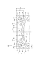
図1に示されるように、第1の実施形態に係るピストン1は、車両のディーゼルエンジンなどの内燃機関に備えられ、シリンダーSの内部を中心軸(ピストン中心軸)Cの延在方向に往復運動するものである。ピストン1は、コネクティングロッドを介して、内燃機関のクランクシャフトに接続されており、ピストン1の往復動エネルギーは、コネクティングロッドを介してクランクシャフトの回転エネルギーに変換される。なお、コネクティングロッド及びクランクシャフトの図示は省略する。
図1に示されるように、第1の実施形態に係るピストン1は、車両のディーゼルエンジンなどの内燃機関に備えられ、シリンダーSの内部を中心軸(ピストン中心軸)Cの延在方向に往復運動するものである。ピストン1は、コネクティングロッドを介して、内燃機関のクランクシャフトに接続されており、ピストン1の往復動エネルギーは、コネクティングロッドを介してクランクシャフトの回転エネルギーに変換される。なお、コネクティングロッド及びクランクシャフトの図示は省略する。
ピストン1は、ピストン頂面2と、摺動側面3と、ピストンスカート4と、を備えている。以下、ピストン1のうちピストン頂面2側を上側、ピストンスカート4側を下側として説明に用いる。
ピストン頂面2は、シリンダーS内で燃焼する空間Eを形成するピストン上端面である。内燃機関の駆動時には、燃料噴射部9から噴射された燃料が空間E内で燃焼されるため、ピストン頂面2は高温となる。ピストン1は、燃焼室5を有している。
摺動側面3は、シリンダーSの内側面と摺動するピストン側面である。摺動側面3には、ピストンリング8A~8Cがそれぞれ嵌め込まれるピストンリング溝3a~3cが形成されている。
第1のピストンリング溝3aには、最もピストン頂面2側に位置する第1のピストンリング8Aが配置される。第2のピストンリング溝3bには、第1のピストンリング溝3a及び第3のピストンリング溝3cの間に位置する第2のピストンリング8Bが配置される。第3のピストンリング溝3cには、最もピストンスカート4側に位置する第3のピストンリング8Cが配置される。
ピストンスカート4は、摺動側面3に沿って下側に延びるように形成されたスカート状の部位である。このピストンスカート4の内部空間7には、コネクティングロッドの小端部が配置される。
燃焼室5は、空気と混合された燃料が燃焼する空間Eの一部であり、ピストン1側に形成された空間である。燃焼室5は、底面5aと側壁5bを有している。底面5aは、例えば、中央(中心軸C)に近づくほど上方に向かって傾斜するように形成されている。この燃焼室5は、側壁5bが内側(中心軸C側)に向かって傾斜するリエントラント型の燃焼室である。燃焼室5の上側には、側壁5bのうち内側に最も突出する部分であるリップ部Lpが形成されている。なお、燃焼室5は、リエントラント型に限られず、側壁5bが中心軸Cに沿うように垂直に形成されるトロイダル型の燃焼室であってもよく、側壁5bが垂直で底面5aも平面に形成されるバスタブ型の燃焼室であってもよい。
また、ピストン1は、燃焼室5(中心軸C)を囲むように環状に形成されたオイルギャラリー6を有している。オイルギャラリー6は、ピストン1の内部に形成された空洞部であり、図示しないオイルジェット孔を通じてエンジンオイルが内部を流れることでピストン1の冷却を行う。
このオイルギャラリー6は、中心軸Cに沿った断面形状(図1に示す断面形状)が略長円形状を成している。具体的に、オイルギャラリー6は、外部傾斜面6a、内部拡大面6b、及び内部傾斜面6cを有している。
外部傾斜面6aは、オイルギャラリー6の外部側面(燃焼室5と反対側の側面)である。外部傾斜面6aは、ピストン頂面2側からピストンスカート4側に向かうほど中心軸Cに近づく平面として形成されている。すなわち、外部傾斜面6aは、下側に向かうほど摺動側面3から離間するように傾斜している。外部傾斜面6aは、オイルギャラリー6のうちピストン1の摺動側面3側(中心軸Cと反対側)に形成されている。なお、外部傾斜面6aは、曲面であってもよく、平面と曲面の両方を含んでいてもよい。
内部拡大面6b及び内部傾斜面6cは、オイルギャラリー6の内部側面(燃焼室5側の側面)を形成しており、燃焼室5の側壁5bに沿うように形成されている。すなわち、オイルギャラリー6の内部側面は、燃焼室5の側壁5bに沿うように形成されている。
内部拡大面6bは、オイルギャラリー6の内部側面の上側(ピストン頂面2側)に形成されている。内部拡大面6bは、燃焼室5側(中心軸C側)に向かってオイルギャラリー6を拡大する部位である。すなわち、内部拡大面6bは、燃焼室5側に向かって張り出して形成されている。具体的に、内部拡大面6bは、燃焼室5の側壁5bのうち中心軸C側に最も突出するリップ部Lpに向かって張り出すように形成されている。内部拡大面6bは、オイルギャラリー6の内部側面と燃焼室5の側壁5bとの間の肉厚が、内部拡大面6bが無い場合と比べて、均等に近づくように形成されている。なお、オイルギャラリー6の内部側面と燃焼室5の側壁5bとの間の肉厚は、強度を確保するために十分な厚さを有している。
内部傾斜面6cは、オイルギャラリー6の内部側面の下側(ピストンスカート4側)に形成され、外部傾斜面6aと略平行に傾斜している平面である。内部傾斜面6cは、燃焼室5の側壁5bに沿うように傾斜して形成されている。
このオイルギャラリー6について、中心軸Cの延在方向における長さをL、中心軸Cに直交する方向おけるピストン1の摺動側面3からオイルギャラリー6までの肉厚のうち上部有効肉厚をA、下部有効肉厚をBとすると、オイルギャラリー6は以下の式(1)、(2)を満たす。なお、式(2)におけるHは、図1に示す燃焼室5の深さ(ピストン頂面2から燃焼室5の最底面までの距離)である。
本実施形態における上部有効肉厚Aは、ピストン1の摺動側面3からオイルギャラリー6のピストン頂面2側までの最も薄い肉厚を意味している。また、本実施形態における下部有効肉厚Bは、図1の断面においてオイルギャラリー6の下端を通り中心軸Cに垂直な仮想直線V1(図1のLを示す下側の寸法線と同一)と外部傾斜面6aに沿った延長線V2との交点をWとした場合におけるピストン1の摺動側面3から交点Wまでの肉厚を意味している。
ここで、図2は、上述した(B-A)/Lに対するピストン1の温度差の例を示すグラフである。図2の縦軸は、ピストン頂面2側の第1のピストンリング8A付近とピストンスカート4側の第3のピストンリング8C付近の温度差である。図2の横軸は、(B-A)/Lである。
図2に示されるように、(B-A)/Lの値が大きくなるほど、ピストン1内の温度差は小さくなる。本実施形態では、温度差によるピストン1の変形を基準値以下に抑えるため、(B-A)/Lqを0.05以上としている。(B-A)/Lqが0.05以上の範囲を矢印Pで示す。なお、図2は(B-A)/Lに対するピストン1の温度差を示す一例であり、本発明は上述した内容に限定されない。
以上説明した第1の実施形態に係る内燃機関のピストン1によれば、摺動側面3からオイルギャラリー6までの肉厚がピストン頂面2側よりピストンスカート4側を厚く形成されているので、オイルギャラリー6を流れるオイルによって燃焼により高温となるピストン頂面2側が十分に冷却される一方で、燃焼による温度上昇が少ないピストンスカート4側が過剰に冷却されることが避けられ、ピストン頂面2側とピストンスカート4側との温度差を少なくしてピストン1の変形を抑制することができる。従って、このピストン1によれば、温度差によりピストンリング溝3a~3cに変形が生じて、ピストンリング8A~8Cの挙動不良による焼付けやシール性が低下することを避けることができ、ピストンリング8A~8Cの信頼性向上及びシール性向上によるブローバイ量の低減などが図られる。
また、このピストン1によれば、ピストン頂面2側からピストンスカート4側に向かうほど中心軸Cに近づく外部傾斜面6aをオイルギャラリー6が有するので、ピストン形状ではなくオイルギャラリー6の形状により、ピストン1の摺動側面3からオイルギャラリー6までの肉厚を下側ほど厚く形成することができ、オイルギャラリー6を流れるオイルによってピストンスカート4側が過剰に冷却されることを避けることができる。
また、図1に示されるように、ピストン1では、ピストン頂面2からオイルギャラリー6の下端までの距離HLが、ピストン頂面2から第2のピストンリング溝3b(すなわち第2のピストンリング8B)までの距離Hrよりも長い。具体的に、オイルギャラリー6は、第1のピストンリング溝3aより上側から、第2のピストンリング溝3bを超えて第3のピストンリング溝3cの近くまで上下に延在するように形成されている。これにより、第2のピストンリング溝3b及び第3のピストンリング溝3cにおいても、オイルギャラリー6内を流れるオイルの冷却効果を適切に得ることができる。
更に、このピストン1では、燃焼室5のリップ部Lpに向かって張り出す内部拡大面6bがオイルギャラリー6に形成されているので、燃焼室5のリップ部Lpを適切に冷却することができる。すなわち、リエントラント型の燃焼室5では、リップ部Lpを設けることにより空気及び空気と混合された燃料の流れが適切にチューニングされ、燃焼室5内の燃焼効率を高めることができる。しかしながら、燃焼室5の側壁5bのうち最も内側に突出するリップ部Lpには熱集中による悪影響が起きやすい。そこで、本実施形態に係るピストン1では、リップ部Lpに向かって凹む内部拡大面6bをオイルギャラリー6が有することで、オイルギャラリー6を流れるオイルによりリップ部Lpを適切に冷却することができる。
しかも、このピストン1では、オイルギャラリー6の内部側面(内部拡大面6b及び内部傾斜面6c)が燃焼室5の側壁5bに沿うように形成されているので、燃焼室5の側壁5bとオイルギャラリー6の内部側面との間のピストン1の肉厚を均等に近づけることができる。これにより、オイルギャラリー6の内部側面と燃焼室5の側壁5bとの間の肉厚が均一ではない場合と比べて、オイルの冷却により側壁5bの温度分布が不均一となることを避けることができる。従って、このピストン1によれば、側壁5bの温度分布が不均一となることで燃焼室5内の空気の温度分布が不均一となり、ピストン1の温度分布も不均一となることで生じる、温度差によるピストン1の変形を招くことを抑制できると共に、燃焼室5内の燃焼効率が低下することを抑制することができる。
[第2~第4の実施形態]
以下、図3~図5を参照して、第2~第4の実施形態について説明する。第2~第4の実施形態に係るピストン10,20,30は、第1の実施形態に係るピストン1と比べて、オイルギャラリーの形状のみが異なっている。以下、各図において同一又は相当部分には同一符号を付し、重複する説明を省略する。
以下、図3~図5を参照して、第2~第4の実施形態について説明する。第2~第4の実施形態に係るピストン10,20,30は、第1の実施形態に係るピストン1と比べて、オイルギャラリーの形状のみが異なっている。以下、各図において同一又は相当部分には同一符号を付し、重複する説明を省略する。
図3に示す第2の実施形態に係るピストン10のオイルギャラリー11は、長円状の断面形状(中心軸Cに沿った断面形状)を有している。オイルギャラリー11は、第1の実施形態と同様に外部傾斜面11aを有しているが、内部拡大面6bのような部位を有していない。オイルギャラリー11の内部側面は外部傾斜面11aに沿った傾斜面をなしている。
また、オイルギャラリー11は、中心軸Cの延在方向における長さL、ピストン1の摺動側面3からオイルギャラリー6までの肉厚の上部有効肉厚A、下部有効肉厚Bについても、第1の実施形態と同様に、上述した式(1)、(2)を満たしている。
なお、ピストン頂面2からオイルギャラリー11の下端までの距離HLが、ピストン頂面2から第2のピストンリング溝3b(すなわち第2のピストンリング8B)までの距離Hrよりも長い点も第1の実施形態と同様である。中心軸Cの延在方向における長さL、上部有効肉厚A、及び下部有効肉厚Bが上述した式(1)、(2)を満たす点と距離HLが距離Hrより長い点は第3及び第4の実施形態についても同様である。
次に、図4に示す第3の実施形態に係るピストン20について説明する。図4に示されるように、第3の実施形態に係るピストン20のオイルギャラリー21は、中心軸Cの延在方向に延在する長円の下側が中心軸Cに向かって、くの字型に折れ曲がった断面形状(中心軸Cに沿った断面形状)を有している。
また、このオイルギャラリー21は、上側の外部垂直面21a及び下側の外部傾斜面21bを有している。外部垂直面21a及び外部傾斜面21bは、オイルギャラリー21の外部側面を形成する。外部垂直面21a及び外部傾斜面21bは、オイルギャラリー21の摺動側面3側(中心軸Cと反対側)に形成されている。外部垂直面21aは、中心軸Cの延在方向に延在する平面であり、外部傾斜面21bは、下側に向かうほど中心軸Cに近づくように傾斜する平面である。なお、外部垂直面21a及び外部傾斜面21bは、曲面であってもよく、平面及び曲面を含んでいてもよい。また、オイルギャラリー21は、上側の内部垂直面21c及び下側の内部傾斜面21dを有している。内部垂直面21c及び内部傾斜面21dは、オイルギャラリー21の内部側面を形成する。
続いて、図5に示す第4の実施形態に係るピストン30について説明する。図5に示されるように、第5の実施形態に係るピストン30のオイルギャラリー31は、中心軸Cの延在方向に延在する長円の上側が摺動側面3側(中心軸Cの反対側)に向かって、くの字型に折れ曲がった断面形状(中心軸Cに沿った断面形状)を有している。
また、このオイルギャラリー31は、上側の外部傾斜面31a及び下側の外部垂直面31bを有している。外部傾斜面31a及び外部垂直面31bは、オイルギャラリー31の摺動側面3側(中心軸Cと反対側)に形成されている。外部傾斜面31aは、下側に向かうほど中心軸Cに近づくように傾斜する平面であり、外部垂直面31bは、中心軸Cの延在方向に延在する平面である。なお、外部傾斜面31a及び外部垂直面31bは、曲面であってもよく、平面及び曲面を含んでいてもよい。
以上説明した第2~第4の実施形態に係るピストン10,20,30においても、摺動側面3からオイルギャラリー11,21,31までの肉厚がピストン頂面2側よりピストンスカート4側を厚く形成されており、第1の実施形態に係るピストン1と同様の効果を得ることができる。
[第5の実施形態]
以下、図6を参照して、第5の実施形態について説明する。第5の実施形態に係るピストン40は、第3の実施形態に係るピストン20と比べて、燃焼室の形状のみが異なっている。
以下、図6を参照して、第5の実施形態について説明する。第5の実施形態に係るピストン40は、第3の実施形態に係るピストン20と比べて、燃焼室の形状のみが異なっている。
図6に示す第5の実施形態に係るピストン40の燃焼室41は、いわゆるバスタブ型の燃焼室である。燃焼室41は、例えば、中心軸Cに垂直な底面(ピストン頂面2に対して略平行な底面)41aと、中心軸Cに沿って伸びる側壁(ピストン頂面2に対して略垂直な側壁)41bと、を有している。なお、底面41aは、中央(中心軸C)に近づくほど上方に向かって傾斜するように形成してもよい。この燃焼室41においては、ピストン頂面2に形成された燃焼室41の開口上端がリップ部Lpとなる。
このピストン40では、オイルギャラリー21の内部垂直面21cが燃焼室41の側壁41bに沿うように形成されている。また、オイルギャラリー21の内部傾斜面21dが燃焼室41の底面41aと側壁41bとの接続部位に沿うように傾斜している。
以上説明した第5の実施形態に係るピストン40においても、オイルギャラリー21の内部垂直面21cが燃焼室41の側壁41bに沿うように形成されているので、燃焼室41の側壁41bとオイルギャラリー21の内部側面との間のピストン40の肉厚を均等に近づけることができる。これにより、オイルギャラリー21の内部側面と燃焼室41の側壁41bとの間の肉厚が均一ではない場合と比べて、オイルの冷却により側壁41bの温度分布が不均一となることを避けることができる。従って、このピストン40によれば、側壁41bの温度分布が不均一となることで燃焼室41内の空気の温度分布が不均一となり、ピストン1の温度分布も不均一となることで生じる、温度差によるピストン1の変形を招くことを抑制できると共に、燃焼室41内の燃焼効率が低下することを抑制することができる。
以上、本発明の好適な実施形態について説明したが、本発明は上述した実施形態に限定されるものではない。
例えば、本発明の一側面は、上述したディーゼルエンジン専用のピストンではなく、ガソリンエンジン用のピストンについても適用可能である。また、オイルギャラリーの形状は、上述したものに限られず、ピストンの摺動側面からオイルギャラリーまでの肉厚がピストン頂面側よりピストンスカート側を厚く形成できる形状であればよい。
また、オイルギャラリーは、必ずしも第2のピストンリング溝の位置より下まで延びている必要はなく、オイルギャラリーの下端が第2のピストンリング溝の上側に位置していてもよい。また、オイルギャラリーの外部傾斜面は、なめらかに傾斜している必要はなく、段差などを有していてもよい。また、第1の実施形態において、側壁41bの温度分布が不均一となり、ピストン1の温度分布も不均一となることにより、温度差によるピストン1の変形を招かなければ、内部拡大面6bは、オイルギャラリー6の内部側面と燃焼室5の側壁5bとの間の肉厚が、内部拡大面6bが無い場合と比べて、完全な均等にはならなくても、均等に近づくように形成されていてもよい。
本発明の一側面によれば、温度差によるピストンの変形を抑制できる内燃機関のピストンを提供できる。
1…ピストン 2…ピストン頂面 3…摺動側面 3a…第1のピストンリング溝 3b…第2のピストンリング溝 3c…第3のピストンリング溝 4…ピストンスカート 5,41…燃焼室 5a,41a…底面 5b,41b…側壁 6a…外部傾斜面 6b…内部拡大面 6c…内部傾斜面 7…内部空間 8A…ピストンリング 8B…ピストンリング 8C…ピストンリング 9…燃料噴射部 1,10,20,30,40…ピストン 6,11,21,31…オイルギャラリー 11a,21b,31a…外部傾斜面 21a,31b…外部垂直面 21c…内部垂直面 21d…内部傾斜面 A…上部有効肉厚 B…下部有効肉厚 C…中心軸(ピストン中心軸) E…空間 S…シリンダー V1…仮想直線 V2…延長線 W…交点
Claims (4)
- ピストン頂面に設けられた燃焼室と、前記燃焼室を囲むように形成されたオイルギャラリーと、を有するピストンであって、
ピストンの摺動側面から前記オイルギャラリーまでの肉厚は、ピストン頂面側よりピストンスカート側が厚く形成されていることを特徴とする内燃機関のピストン。 - 前記オイルギャラリーは、ピストン頂面側からピストンスカート側に向かうほどピストン中心軸に近づく外部傾斜面を有する、請求項1に記載の内燃機関のピストン。
- 前記オイルギャラリーの内部側面は、前記燃焼室の側壁に沿うように形成されている、請求項1又は2に記載の内燃機関のピストン。
- 前記燃焼室の側壁は、前記燃焼室の内側に突出するリップ部を有しており、
前記オイルギャラリーの内部側面は、前記リップ部に向かって張り出す内部拡大面を有している、請求項3に記載の内燃機関のピストン。
Priority Applications (2)
| Application Number | Priority Date | Filing Date | Title |
|---|---|---|---|
| CN201480016746.XA CN105143653B (zh) | 2013-03-21 | 2014-03-12 | 内燃机的活塞 |
| US14/778,417 US9850847B2 (en) | 2013-03-21 | 2014-03-12 | Piston for internal combustion engine |
Applications Claiming Priority (2)
| Application Number | Priority Date | Filing Date | Title |
|---|---|---|---|
| JP2013058058 | 2013-03-21 | ||
| JP2013-058058 | 2013-03-21 |
Publications (1)
| Publication Number | Publication Date |
|---|---|
| WO2014148331A1 true WO2014148331A1 (ja) | 2014-09-25 |
Family
ID=51580018
Family Applications (1)
| Application Number | Title | Priority Date | Filing Date |
|---|---|---|---|
| PCT/JP2014/056468 Ceased WO2014148331A1 (ja) | 2013-03-21 | 2014-03-12 | 内燃機関のピストン |
Country Status (4)
| Country | Link |
|---|---|
| US (1) | US9850847B2 (ja) |
| JP (1) | JP6430135B2 (ja) |
| CN (1) | CN105143653B (ja) |
| WO (1) | WO2014148331A1 (ja) |
Families Citing this family (1)
| Publication number | Priority date | Publication date | Assignee | Title |
|---|---|---|---|---|
| US11650173B2 (en) * | 2019-11-01 | 2023-05-16 | Caterpillar Inc. | Grading a piston with deposits using thermal scan data |
Citations (7)
| Publication number | Priority date | Publication date | Assignee | Title |
|---|---|---|---|---|
| JPS6217347A (ja) * | 1985-07-16 | 1987-01-26 | Mitsubishi Heavy Ind Ltd | 内燃機関のピストン |
| JPH03117657A (ja) * | 1989-09-29 | 1991-05-20 | Mitsubishi Heavy Ind Ltd | 内燃機関用ピストン |
| JP2002250251A (ja) * | 2001-02-21 | 2002-09-06 | Toyota Motor Corp | 内燃機関用ピストン |
| JP2003138984A (ja) * | 2001-11-02 | 2003-05-14 | Yanmar Co Ltd | 内燃機関のピストン構造 |
| JP2007146819A (ja) * | 2005-11-30 | 2007-06-14 | Komatsu Ltd | エンジン用ピストンおよびエンジン用ピストンの冷却方法 |
| JP2011017263A (ja) | 2009-07-07 | 2011-01-27 | Isuzu Motors Ltd | 内燃機関の設計方法、ピストン構造及び内燃機関 |
| JP2012519251A (ja) * | 2009-02-27 | 2012-08-23 | フェデラル−モーグル コーポレイション | 中央方向オイルフローおよびピストンピン潤滑供給部を有するピストン、ならびにその構成方法 |
Family Cites Families (6)
| Publication number | Priority date | Publication date | Assignee | Title |
|---|---|---|---|---|
| JPS60187325A (ja) | 1984-03-06 | 1985-09-24 | Noritake Co Ltd | 分散混合器への流体注入方法及びその装置 |
| JPS60187325U (ja) * | 1984-05-24 | 1985-12-12 | 日産自動車株式会社 | ピストンのオイル冷却装置 |
| US6327962B1 (en) * | 1999-08-16 | 2001-12-11 | Caterpillar Inc. | One piece piston with supporting piston skirt |
| DE112004002568T5 (de) | 2004-01-07 | 2006-11-30 | Komatsu Ltd. | Kolben für einen Verbrennungsmotor |
| CN102667127B (zh) | 2009-11-25 | 2014-05-28 | 丰田自动车株式会社 | 内燃机用活塞以及内燃机 |
| WO2012125961A1 (en) * | 2011-03-17 | 2012-09-20 | Cummins Intellectual Property, Inc. | Piston for internal combustion engine |
-
2014
- 2014-03-12 US US14/778,417 patent/US9850847B2/en not_active Expired - Fee Related
- 2014-03-12 WO PCT/JP2014/056468 patent/WO2014148331A1/ja not_active Ceased
- 2014-03-12 CN CN201480016746.XA patent/CN105143653B/zh not_active Expired - Fee Related
- 2014-03-20 JP JP2014058433A patent/JP6430135B2/ja not_active Expired - Fee Related
Patent Citations (7)
| Publication number | Priority date | Publication date | Assignee | Title |
|---|---|---|---|---|
| JPS6217347A (ja) * | 1985-07-16 | 1987-01-26 | Mitsubishi Heavy Ind Ltd | 内燃機関のピストン |
| JPH03117657A (ja) * | 1989-09-29 | 1991-05-20 | Mitsubishi Heavy Ind Ltd | 内燃機関用ピストン |
| JP2002250251A (ja) * | 2001-02-21 | 2002-09-06 | Toyota Motor Corp | 内燃機関用ピストン |
| JP2003138984A (ja) * | 2001-11-02 | 2003-05-14 | Yanmar Co Ltd | 内燃機関のピストン構造 |
| JP2007146819A (ja) * | 2005-11-30 | 2007-06-14 | Komatsu Ltd | エンジン用ピストンおよびエンジン用ピストンの冷却方法 |
| JP2012519251A (ja) * | 2009-02-27 | 2012-08-23 | フェデラル−モーグル コーポレイション | 中央方向オイルフローおよびピストンピン潤滑供給部を有するピストン、ならびにその構成方法 |
| JP2011017263A (ja) | 2009-07-07 | 2011-01-27 | Isuzu Motors Ltd | 内燃機関の設計方法、ピストン構造及び内燃機関 |
Also Published As
| Publication number | Publication date |
|---|---|
| JP6430135B2 (ja) | 2018-11-28 |
| JP2014206159A (ja) | 2014-10-30 |
| CN105143653B (zh) | 2017-11-03 |
| US9850847B2 (en) | 2017-12-26 |
| US20160084195A1 (en) | 2016-03-24 |
| CN105143653A (zh) | 2015-12-09 |
Similar Documents
| Publication | Publication Date | Title |
|---|---|---|
| US7854191B2 (en) | Three-piece oil ring and combination of the three-piece oil ring and piston | |
| CN100497920C (zh) | 内燃机和缸套安装环 | |
| US9228530B2 (en) | Piston for internal combustion engine | |
| JP6527203B2 (ja) | 冷却空洞が改善されたピストン | |
| US20110114040A1 (en) | Cooling structure for internal combustion engine | |
| CN105518356B (zh) | 活塞环 | |
| CN106460721B (zh) | 用于高温内燃机的、带有梯形的第二环形槽的活塞 | |
| JP6230547B2 (ja) | 内燃機関用のピストンリング | |
| US9567940B2 (en) | Engine arrangement for enhanced cooling | |
| JP6430135B2 (ja) | 内燃機関のピストン | |
| CN110506173A (zh) | 内燃机用活塞和活塞环 | |
| KR101593543B1 (ko) | 내연기관용 피스톤 | |
| JP5964092B2 (ja) | 多気筒内燃機関 | |
| JP5932739B2 (ja) | 内燃機関のシリンダブロック | |
| JP6528720B2 (ja) | ピストン | |
| CN105604727B (zh) | 发动机活塞 | |
| JP2012017654A (ja) | 内燃機関 | |
| KR20140032455A (ko) | 언더크라운 지지 부재를 가진 피스톤 | |
| US20170130656A1 (en) | Isobaric Piston Assembly | |
| JP2018025110A (ja) | 内燃機関 | |
| JP2025077736A (ja) | 内燃機関用ピストン | |
| CN107850004A (zh) | 用于内燃机的活塞 | |
| JP2013164020A (ja) | 内燃機関のピストン | |
| JP2007162596A (ja) | シリンダブロック及び内燃機関 | |
| JP2009167970A (ja) | 内燃機関用ピストン |
Legal Events
| Date | Code | Title | Description |
|---|---|---|---|
| WWE | Wipo information: entry into national phase |
Ref document number: 201480016746.X Country of ref document: CN |
|
| 121 | Ep: the epo has been informed by wipo that ep was designated in this application |
Ref document number: 14767906 Country of ref document: EP Kind code of ref document: A1 |
|
| WWE | Wipo information: entry into national phase |
Ref document number: 14778417 Country of ref document: US |
|
| NENP | Non-entry into the national phase |
Ref country code: DE |
|
| WWE | Wipo information: entry into national phase |
Ref document number: 2014767906 Country of ref document: EP |