WO2014148464A1 - リング圧延用素材 - Google Patents
リング圧延用素材 Download PDFInfo
- Publication number
- WO2014148464A1 WO2014148464A1 PCT/JP2014/057262 JP2014057262W WO2014148464A1 WO 2014148464 A1 WO2014148464 A1 WO 2014148464A1 JP 2014057262 W JP2014057262 W JP 2014057262W WO 2014148464 A1 WO2014148464 A1 WO 2014148464A1
- Authority
- WO
- WIPO (PCT)
- Prior art keywords
- ring rolling
- peripheral surface
- height
- ring
- rolling material
- Prior art date
- Legal status (The legal status is an assumption and is not a legal conclusion. Google has not performed a legal analysis and makes no representation as to the accuracy of the status listed.)
- Ceased
Links
Images



Classifications
-
- B—PERFORMING OPERATIONS; TRANSPORTING
- B21—MECHANICAL METAL-WORKING WITHOUT ESSENTIALLY REMOVING MATERIAL; PUNCHING METAL
- B21H—MAKING PARTICULAR METAL OBJECTS BY ROLLING, e.g. SCREWS, WHEELS, RINGS, BARRELS, BALLS
- B21H1/00—Making articles shaped as bodies of revolution
- B21H1/06—Making articles shaped as bodies of revolution rings of restricted axial length
-
- F—MECHANICAL ENGINEERING; LIGHTING; HEATING; WEAPONS; BLASTING
- F01—MACHINES OR ENGINES IN GENERAL; ENGINE PLANTS IN GENERAL; STEAM ENGINES
- F01D—NON-POSITIVE DISPLACEMENT MACHINES OR ENGINES, e.g. STEAM TURBINES
- F01D25/00—Component parts, details, or accessories, not provided for in, or of interest apart from, other groups
- F01D25/005—Selecting particular materials
-
- B—PERFORMING OPERATIONS; TRANSPORTING
- B21—MECHANICAL METAL-WORKING WITHOUT ESSENTIALLY REMOVING MATERIAL; PUNCHING METAL
- B21B—ROLLING OF METAL
- B21B45/00—Devices for surface or other treatment of work, specially combined with or arranged in, or specially adapted for use in connection with, metal-rolling mills
- B21B45/004—Heating the product
-
- B—PERFORMING OPERATIONS; TRANSPORTING
- B21—MECHANICAL METAL-WORKING WITHOUT ESSENTIALLY REMOVING MATERIAL; PUNCHING METAL
- B21D—WORKING OR PROCESSING OF SHEET METAL OR METAL TUBES, RODS OR PROFILES WITHOUT ESSENTIALLY REMOVING MATERIAL; PUNCHING METAL
- B21D19/00—Flanging or other edge treatment, e.g. of tubes
- B21D19/02—Flanging or other edge treatment, e.g. of tubes by continuously-acting tools moving along the edge
- B21D19/04—Flanging or other edge treatment, e.g. of tubes by continuously-acting tools moving along the edge shaped as rollers
-
- B—PERFORMING OPERATIONS; TRANSPORTING
- B21—MECHANICAL METAL-WORKING WITHOUT ESSENTIALLY REMOVING MATERIAL; PUNCHING METAL
- B21J—FORGING; HAMMERING; PRESSING METAL; RIVETING; FORGE FURNACES
- B21J1/00—Preparing metal stock or similar ancillary operations prior, during or post forging, e.g. heating or cooling
- B21J1/02—Preliminary treatment of metal stock without particular shaping, e.g. salvaging segregated zones, forging or pressing in the rough
-
- B—PERFORMING OPERATIONS; TRANSPORTING
- B21—MECHANICAL METAL-WORKING WITHOUT ESSENTIALLY REMOVING MATERIAL; PUNCHING METAL
- B21J—FORGING; HAMMERING; PRESSING METAL; RIVETING; FORGE FURNACES
- B21J1/00—Preparing metal stock or similar ancillary operations prior, during or post forging, e.g. heating or cooling
- B21J1/02—Preliminary treatment of metal stock without particular shaping, e.g. salvaging segregated zones, forging or pressing in the rough
- B21J1/025—Preliminary treatment of metal stock without particular shaping, e.g. salvaging segregated zones, forging or pressing in the rough affecting grain orientation
-
- B—PERFORMING OPERATIONS; TRANSPORTING
- B21—MECHANICAL METAL-WORKING WITHOUT ESSENTIALLY REMOVING MATERIAL; PUNCHING METAL
- B21J—FORGING; HAMMERING; PRESSING METAL; RIVETING; FORGE FURNACES
- B21J5/00—Methods for forging, hammering, or pressing; Special equipment or accessories therefor
- B21J5/02—Die forging; Trimming by making use of special dies ; Punching during forging
-
- B—PERFORMING OPERATIONS; TRANSPORTING
- B21—MECHANICAL METAL-WORKING WITHOUT ESSENTIALLY REMOVING MATERIAL; PUNCHING METAL
- B21J—FORGING; HAMMERING; PRESSING METAL; RIVETING; FORGE FURNACES
- B21J5/00—Methods for forging, hammering, or pressing; Special equipment or accessories therefor
- B21J5/02—Die forging; Trimming by making use of special dies ; Punching during forging
- B21J5/022—Open die forging
-
- B—PERFORMING OPERATIONS; TRANSPORTING
- B21—MECHANICAL METAL-WORKING WITHOUT ESSENTIALLY REMOVING MATERIAL; PUNCHING METAL
- B21K—MAKING FORGED OR PRESSED METAL PRODUCTS, e.g. HORSE-SHOES, RIVETS, BOLTS OR WHEELS
- B21K1/00—Making machine elements
- B21K1/76—Making machine elements elements not mentioned in one of the preceding groups
- B21K1/761—Making machine elements elements not mentioned in one of the preceding groups rings
-
- C—CHEMISTRY; METALLURGY
- C22—METALLURGY; FERROUS OR NON-FERROUS ALLOYS; TREATMENT OF ALLOYS OR NON-FERROUS METALS
- C22C—ALLOYS
- C22C19/00—Alloys based on nickel or cobalt
- C22C19/03—Alloys based on nickel or cobalt based on nickel
- C22C19/05—Alloys based on nickel or cobalt based on nickel with chromium
-
- C—CHEMISTRY; METALLURGY
- C22—METALLURGY; FERROUS OR NON-FERROUS ALLOYS; TREATMENT OF ALLOYS OR NON-FERROUS METALS
- C22C—ALLOYS
- C22C19/00—Alloys based on nickel or cobalt
- C22C19/03—Alloys based on nickel or cobalt based on nickel
- C22C19/05—Alloys based on nickel or cobalt based on nickel with chromium
- C22C19/051—Alloys based on nickel or cobalt based on nickel with chromium and Mo or W
- C22C19/055—Alloys based on nickel or cobalt based on nickel with chromium and Mo or W with the maximum Cr content being at least 20% but less than 30%
-
- C—CHEMISTRY; METALLURGY
- C22—METALLURGY; FERROUS OR NON-FERROUS ALLOYS; TREATMENT OF ALLOYS OR NON-FERROUS METALS
- C22C—ALLOYS
- C22C19/00—Alloys based on nickel or cobalt
- C22C19/03—Alloys based on nickel or cobalt based on nickel
- C22C19/05—Alloys based on nickel or cobalt based on nickel with chromium
- C22C19/051—Alloys based on nickel or cobalt based on nickel with chromium and Mo or W
- C22C19/056—Alloys based on nickel or cobalt based on nickel with chromium and Mo or W with the maximum Cr content being at least 10% but less than 20%
-
- F—MECHANICAL ENGINEERING; LIGHTING; HEATING; WEAPONS; BLASTING
- F01—MACHINES OR ENGINES IN GENERAL; ENGINE PLANTS IN GENERAL; STEAM ENGINES
- F01D—NON-POSITIVE DISPLACEMENT MACHINES OR ENGINES, e.g. STEAM TURBINES
- F01D5/00—Blades; Blade-carrying members; Heating, heat-insulating, cooling or antivibration means on the blades or the members
- F01D5/02—Blade-carrying members, e.g. rotors
-
- F—MECHANICAL ENGINEERING; LIGHTING; HEATING; WEAPONS; BLASTING
- F01—MACHINES OR ENGINES IN GENERAL; ENGINE PLANTS IN GENERAL; STEAM ENGINES
- F01D—NON-POSITIVE DISPLACEMENT MACHINES OR ENGINES, e.g. STEAM TURBINES
- F01D5/00—Blades; Blade-carrying members; Heating, heat-insulating, cooling or antivibration means on the blades or the members
- F01D5/02—Blade-carrying members, e.g. rotors
- F01D5/06—Rotors for more than one axial stage, e.g. of drum or multiple disc type; Details thereof, e.g. shafts, shaft connections
-
- C—CHEMISTRY; METALLURGY
- C22—METALLURGY; FERROUS OR NON-FERROUS ALLOYS; TREATMENT OF ALLOYS OR NON-FERROUS METALS
- C22F—CHANGING THE PHYSICAL STRUCTURE OF NON-FERROUS METALS AND NON-FERROUS ALLOYS
- C22F1/00—Changing the physical structure of non-ferrous metals or alloys by heat treatment or by hot or cold working
- C22F1/10—Changing the physical structure of non-ferrous metals or alloys by heat treatment or by hot or cold working of nickel or cobalt or alloys based thereon
-
- F—MECHANICAL ENGINEERING; LIGHTING; HEATING; WEAPONS; BLASTING
- F05—INDEXING SCHEMES RELATING TO ENGINES OR PUMPS IN VARIOUS SUBCLASSES OF CLASSES F01-F04
- F05D—INDEXING SCHEME FOR ASPECTS RELATING TO NON-POSITIVE-DISPLACEMENT MACHINES OR ENGINES, GAS-TURBINES OR JET-PROPULSION PLANTS
- F05D2220/00—Application
- F05D2220/30—Application in turbines
- F05D2220/32—Application in turbines in gas turbines
Definitions
- the present invention relates to a ring rolling material that is rolled to form a ring product material to be used in a high temperature environment.
- An example of an apparatus in which parts such as heat-resistant steel and super heat-resistant alloy are frequently used is a gas turbine.
- a gas turbine blade-shaped blades are respectively arranged on the outer periphery of a plurality of ring-shaped turbine disks mounted in a multistage manner on the rotation shaft thereof, and the fluid flow in the axial direction (axial direction of the rotation shaft) is rotationally moved. Power is generated by converting to.
- the air sucked from the front of the gas turbine is compressed by the subsequent multi-stage axial compression section, and further, the gas mixed with the fuel in the compressed air is combusted in the combustor disposed at a high temperature and high pressure.
- the combustion gas is generated.
- the combustion gas collides with blades attached to the turbine disk while flowing in the axial direction along the flow path in the outer peripheral portion of the turbine disk, and the axial movement is converted into rotational movement. It is intended to rotate at high speed.
- the driving force of this rotation acts so as to cause continuous rotation by rotating the turbine disk of the previous stage via the rotating shaft and compressing the air.
- Ni-based superalloy eg, 718 alloy
- a method of precipitating particles that suppress the coarsening of crystal grains is an effective means.
- Patent Document 2 a method of obtaining fine grains by promoting a miniaturization phenomenon by introducing strain into a material during hot working has been proposed.
- a Ni-base superalloy is expensive as compared with a normal steel material because a rare metal is a main component.
- near net forging is often used in which a near net shape material close to a finished shape is cut as a cutting material, thereby reducing the amount of chips during cutting and reducing the manufacturing cost.
- hot forging is used for near net forging.
- a cylindrical billet is formed into a disk shape by upsetting forging, then a center part is drilled, and a ring having a predetermined diameter is formed by ring rolling, and finally, The hot forging process which shape
- JP 61-238936 A Japanese Patent Laid-Open No. 7-138719 JP 2011-56548 A
- the ring-shaped molded object which has a some near net shape at a time by hot rolling using the main roll and mandrel roll of a special shape using one ring-shaped raw material like patent document 3 is obtained. It has also been proposed to try. In this proposal, unlike the above-described ring rolling material having a rectangular cross-sectional shape, a ring rolling material having a substantially circular or substantially elliptical cross section is used.
- Patent Document 3 aims to eliminate the hot forging process, and is significantly different from the conventional technique. Moreover, the examination of the shape of the ring rolling material is insufficient, and if an attempt is made to produce the ring rolling material having the shape shown in Patent Document 3 as a single molded product as it is, local abnormal heat generation may occur. .
- the object of the present invention is to suppress an excessive temperature rise during ring rolling and to introduce a uniform and optimum strain on the entire surface of the ring rolling material.
- An object of the present invention is to provide a material for ring rolling used as a material for rolling, in particular, a material for rotating parts used in a high temperature part such as a gas turbine.
- the material for ring rolling according to one aspect of the present invention is a material for ring rolling provided with a radially outer peripheral surface and an inner peripheral surface, and the main rolls are disposed so as to face and contact the outer peripheral surface and the inner peripheral surface, respectively.
- a ring rolling mill equipped with a mandrel roll, by narrowing the radial interval between the main roll and the mandrel roll, in a ring rolling material that is hot-rolled, a one-side cross section of the ring rolling material Is located closer to the outer peripheral surface than the center in the thickness direction of the one-side cross section, and the shape of the one-side cross section has a height from the center line that bisects the one-side cross section in the height direction. It includes a height-decreasing portion that decreases toward the peripheral surface, and is formed to be substantially line symmetric with the center line as the axis of symmetry, and the height of the inner peripheral surface is the maximum height of the ring rolling material. Versus And and it reached 50% or less than 20% Te. With this configuration, an unconstrained portion is formed in the ring rolling material during forming by the ring rolling mill, and a free space is formed when the ring rolling material is deformed during ring rolling.
- the number of man-hours for controlling the structure when a plurality of heats are increased.
- heat generation during ring rolling can be set to an appropriate temperature, as compared with ring rolling using a conventional shape. Since the number of heats can be reduced, the manufacturing time can be shortened.
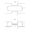
- FIG. 1 (a) and 1 (b) are cross-sectional views schematically illustrating a process for forming a ring rolling material according to an embodiment of the present invention.
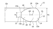
- FIG. 2 is a half sectional view schematically showing an example of a ring rolling material according to an embodiment of the present invention.
- FIG. 3 is a half sectional view schematically showing a first modification of the ring rolling material according to the embodiment of the present invention.
- FIG. 4 is a half sectional view schematically showing a second modification of the ring rolling material according to the embodiment of the present invention.
- FIG. 5 is a half sectional view schematically showing a third modification of the ring rolling material according to the embodiment of the present invention.
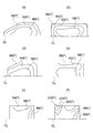
- FIGS. 7A to 7C are diagrams showing temperature distributions obtained by numerical analysis for an analysis example of a ring rolling material according to an embodiment of the present invention.
- FIGS. 7D to 7F are diagrams showing temperature distributions obtained by numerical analysis for an analysis example of a ring rolling material having a conventional structure.
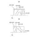
- Fig.8 (a) is a figure which shows the distortion distribution obtained by the numerical analysis about the example of an analysis of the raw material for ring rolling which concerns on embodiment of this invention.
- FIG.8 (b) is a figure which shows the strain distribution obtained by the numerical analysis about the example of an analysis of the raw material for ring rolling of a conventional structure.
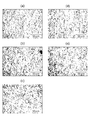
- FIGS. 9 (a) to 9 (e) are enlarged photographs showing the metal structures of the upper part, inner diameter part, center part, outer diameter part, and lower part of the ring rolling material according to the embodiment of the present invention.
- Ni-base superalloy with excellent high-temperature strength is adopted as a material for ring rolling.
- Ni-based superalloy heat-resistant gold material Ni: 50 to 55%, Cr: 15 to 22%, Nb: 4.5 to 6.5%, Mo: 2.5 to 3 in mass% 0.5%, Ti: 0.6 to 1.2%, Al: 0.2 to 0.8%, the balance being Ni-based super heat resistant equivalent to 718 alloy having a component composition of Fe and inevitable impurities
- a disk-shaped Ni-based superalloy 1 having a predetermined height is heated to a hot working temperature.
- FIG. 1B using upper and lower molds (upper and lower molds) 2 and 3 that are provided in a forging device, a hot press device, and the like and have a frustoconical convex portion at the center.
- the thin-walled portion 4 shown by the hatched portion in FIG. 1 (b)
- the central thin-walled portion 4 is cut out, thereby forming a ring rolling material.
- FIG. 2 An example of the one-side cross section of the ring rolling raw material 11 obtained by the shaping
- a direction along the center axis CA of the ring rolling material 11 is defined as a “height direction”
- a direction orthogonal to the center axis CA is defined as a “thickness direction”.
- the “height direction” and the “thickness direction” mean the same directions as in FIG.
- FIG. 2 is a half sectional view schematically showing the ring rolling material 11 formed in an axially symmetric shape (shape 1) with respect to the central axis CA.
- the “one-side cross-sectional view” is a drawing in which the ring rolling material 11 is drawn with the part on one side in the thickness direction with respect to the central axis CA, that is, the left part on the drawing omitted. Means.
- Such a material for ring rolling 11 includes a radially outer peripheral surface 12 and an inner peripheral surface 13.
- the ring rolling material 11 includes an outer peripheral portion 14 including an outer peripheral surface 12.
- the outer peripheral surface 12 is a part of the periphery of the outer peripheral portion 14 forming the outline of the one-side cross section.
- the outer peripheral portion 14 is positioned closer to the outer periphery of the ring rolling material 11 with respect to a boundary line (not shown) that linearly connects both end portions 12a in the height direction of the outer peripheral surface 12.
- the one-side cross-sectional shape of the ring rolling material 11 shown in the figure has a straight portion 15 near the central portion in the thickness direction, and the straight portion 15 includes an end face 16 in the height direction extending linearly.
- the length of the straight portion 15, preferably the length of the end face 16 of the straight portion 15 is about 2/3 times the maximum height H ⁇ b> 1 of the ring rolling material 11.
- a height reducing portion 17 connected to such a straight portion 15 is provided, and the height reducing portion 17 is an inner portion whose height from the center line CL that bisects one side cross section in the height direction contacts the mandrel roll. It is formed in a tapered shape so as to gradually decrease toward the peripheral surface 13.
- the height Hin on the inner diameter end (inner peripheral surface 13) side is 1/3 times (33%) or more and 1/2 times (50%) or less of the maximum height H1 of the material 11 for ring rolling. It has become.
- the length of the projection onto the line CL is set in a range of 0.2 times or more and 1.5 times or less with respect to the maximum height H1 of the ring rolling material 11, and the height reducing portion 17
- the outer peripheral surface 12 formed on the roll side is formed in a shape that tapers from both end portions 12a in the height direction toward both end portions 13a in the height direction of the inner peripheral surface 13 while including a linear portion having a certain length. Yes.
- the shape of the one-side cross section is formed in substantially line symmetry with the center line CL as an axis of symmetry.
- center of gravity (or centroid) G of the cross section on one side of the ring rolling material 11 is located on the main roll side, that is, on the outer peripheral surface 12 side, from the center CP in the thickness direction of the ring rolling material 11,
- the center CP in the thickness direction is indicated by a cross mark
- the position of the center of gravity G is indicated by a black circle mark.
- FIGS. 3 to 5 show first to third modifications of the ring rolling material 11, respectively.
- the portion 12c is provided with a tapered portion, and an intermediate portion 12d connecting the upper and lower tapered portions has a linear shape.
- the upper portion 12b and the lower portion 12c of the outer peripheral surface 12 are provided with tapered portions, and the intermediate portion 12d connecting the upper and lower tapered portions is linearly formed.
- the contact area between the main roll and the ring rolling material 11 increases, and as a result, stable ring rolling becomes possible.
- the method of adjusting the shape by machining for example, when forming the ring rolling material described above, to obtain the shape of FIG.
- the method of machining for example, when forming the ring rolling material described above, to obtain the shape of FIG.
- the method of machining there is a method of using a mold having the formed upper and lower molds 2 and 3. In the method of machining, the accuracy of the shape can be increased, but the yield decreases. Therefore, it is advantageous to form the shape of FIG. 3 by the die shape at the time of hot forging (including hot pressing).
- the material 11 for ring rolling (shape 3) of the one side cross-sectional view of the second modification shown in FIG. 4 has an inner peripheral surface 13 from both end portions 12a in the height direction of the outer peripheral surface 12 formed on the main roll side. It has a shape that tapers linearly toward both end portions 13a in the height direction.
- the method of adjusting the shape by machining for example, the shape of FIG.
- the outer peripheral surface 12 that comes into contact with the main roll is formed in a curved shape.
- the curved portion that first comes into contact with the main roll is processed into a flat shape,
- the contact area with the ring rolling material 11 increases, and as a result, stable ring rolling becomes possible.
- the entire curved surface on the outer peripheral surface 12 side may be processed to be flat.
- the ring rolling blank 11 (shape 4) of the one side sectional view of the third modification shown in FIG. 5 the inner peripheral surface 13 in contact with the mandrel roll is formed in a straight shape, and the other portions are in a curved shape. Is formed.
- the shapes illustrated in FIGS. 2 to 5 the shapes shown in FIGS. 2 and 3 can be more stably ring-rolled.
- the center of gravity G of the ring rolling material 11 is the meat of the ring rolling material 11. It is located on the main roll side from the center CP in the thickness direction, that is, on the outer peripheral surface 12 side.
- the contact area between the mandrel roll and the ring rolling material 11 can be reduced.
- ring rolling can be performed while reducing the load during ring rolling. Therefore, in particular, it is possible to suppress local heat generation of the ring rolling material 11 that comes into contact with the mandrel roll.
- the height Hin of the inner peripheral surface 13 of the ring rolling material 11 is 20% or more and 50% or less with respect to the maximum height H1 of the ring rolling material 11, so that the ring rolling material is used during ring rolling.
- deformation occurs sequentially in the height reduction portion 17 of 11 and ring rolling can be performed with a relatively low pressing force.
- the height Hin of the inner peripheral surface 13 is less than 20% with respect to the maximum height H1 of the ring rolling material 11, the contact area between the mandrel roll and the inner peripheral surface 13 is reduced.
- the rolled material 11 tends to fall down in either the upper or lower direction, and as a result, the ring rolling tends to become unstable.
- the minimum of the preferable height Hin of the internal peripheral surface 13 which can acquire the above-mentioned effect more reliably is 25% with respect to the maximum thickness H1 of the raw material 11 for ring rolling, More preferably, it is 33%. is there.
- the upper limit of the preferable height Hin of the inner peripheral surface 13 is 45%, more preferably 40%, with respect to the maximum thickness H1 of the ring rolling material 11.
- “the height of the inner peripheral surface 13” refers to the interval between both end portions 13 a in the height direction of the inner peripheral surface 13 having a large difference in curvature with respect to the curvature of the inclined surface 18 of the height reducing portion 17. For example, in the case of the one-side cross-sectional views of FIGS.
- the height of the inner peripheral surface 13 refers to the length of a linear portion that contacts the mandrel roll.
- the measurement of the height Hin of the inner peripheral surface 13 is unclear because there are slight curved surfaces or irregularities on the inner peripheral surface 13, from the first contact point with the mandrel roll to the outer peripheral side. It is good to measure the location which is located in the range within 20 mm, and has a curvature with a big difference with respect to the curvature of the height reduction part 17.
- the ring rolling material 11 is formed substantially symmetrical with respect to the center line CL as an axis of symmetry.
- the substantially line-symmetric shape with the center line CL as the axis of symmetry enables stable ring rolling during ring rolling.
- substantially line symmetry since the material for ring rolling is formed by hot forging as described above, for example, if a die whose outer peripheral surface 12 is not restrained is used, complete line symmetry is obtained. There may not be. For this reason, “substantially line symmetry” described in the present invention is defined as allowing the shape error, deviation, and the like that occur when the ring rolling material is formed. Furthermore, in the embodiment of the present invention, as shown in FIGS.
- the height reducing portion 17 becomes a free space when the ring rolling material 11 is deformed during molding by a ring rolling mill, and in particular, excessive heat generation of the ring rolling material 11 on the mandrel roll side can be prevented.
- the height reducing portion 17 is formed by pressing the center using the upper and lower molds 2 and 3 having a frustoconical convex portion at the center portion. Can be formed. In this case, as the angle of the frustoconical convex portion becomes shallower, the length of the height reducing portion 17 in the thickness direction becomes longer. However, if the length in the thickness direction of the height reduction portion 17 is excessively long, the processing time of the height reduction portion 17 may be long during ring rolling.
- the length of the height reducing portion 17 in the thickness direction decreases.
- the length is excessively shortened, the mortar-shaped removed portion after pressing increases and the yield is deteriorated.
- the pressing surface area of the convex portion increases, a large pressing force is required, and a special forging device that can apply a large load is required.
- the temperature of the ring rolling material 11 may be locally increased during ring rolling.
- the length of the height reducing portion 17 in the thickness direction preferably the length of the inclined surface 18 of the height reducing portion 17 projected onto the center line CL in the height direction is
- the maximum height H1 of the ring rolling material 11 is 0.2 times or more and 1.5 times or less.
- the lower limit of the length in the thickness direction in the preferred height reduction portion 17 is 0.5 times, more preferably 0.6 times.
- the upper limit of the length in the thickness direction in the preferred height reducing portion 17 is 1.1 times, and more preferably 1.0 times.
- the outer peripheral portion 14 that contacts the main roll of the ring rolling material 11 according to the embodiment of the present invention is formed in a shape that tapers toward the outer periphery.
- the ring rolling material 11 shown in FIGS. 2 to 5 is all formed in a tapered shape. When such a shape is applied, for example, even when a die that does not restrain the outer peripheral surface 12 by hot forging at the time of forming a ring rolling material can be used as it is for ring rolling, it is economical. It is. As described above, when a flat portion is provided on the outer peripheral surface 12 in contact with the main roll during ring rolling, the ring rolling is stabilized.
- a flat portion (a linear shape portion of the outer peripheral surface 12 in the drawing) having a length of about 1/6 times or more and 1/3 times or less of the maximum height H1.
- the linear portion 15 having both end surfaces 16 in the height direction extending substantially linearly may be provided between the outer peripheral portion 14 and the height reducing portion 17.
- the straight portion 15 is more stable in ring rolling and more easily obtains a desired shape if a flat portion for pressing with the axial roll is present.
- the length of the straight portion 15 in the thickness direction preferably the length of the end face 16 of the straight portion 15 is greater than 0 times the maximum height H1 of the ring rolling material 11 and 2/3. Is less than double.
- the thickness (wall thickness) of the ring rolling material 11 is preferably 0.5 times or more with respect to the maximum height H1 of the ring rolling material 11. This is because the ring rolling blank 11 according to an embodiment of the present invention is further processed into a final product shape by hot forging (including forging and pressing under hot and constant temperature) after ring rolling, so that the thickness is excessively large. It is determined in consideration of the fact that if it is thin, it may be buckled by subsequent hot forging.
- the angle of the ring rolling material 11 indicated by ⁇ in in FIG. 2 is preferably 20 ° or more.
- the angle ⁇ in is less than 20 °, the height reducing portion 17 becomes long and the ring rolling time tends to be long. Further, the weight of the thin portion 4 to be cut after hot working such as hot forging or hot pressing increases, and as a result, the yield may be deteriorated.
- the angle ⁇ in exceeds 70 °, local heat generation on the inner peripheral surface 13 is likely to occur during ring rolling.
- the Ni-based superalloy 1 is not filled in the upper and lower molds 2 and 3 during hot working, making it difficult to obtain a desired shape.
- the lower limit of the preferable angle ⁇ in that can prevent these problems more reliably is 25 °.
- the upper limit of the preferred angle ⁇ in is 45 °, more preferably 30 °.
- Ring rolling is performed on the above-described ring rolling material 11 using a ring rolling mill.
- the ring rolling mill may be provided with guide rolls (holding rolls) and fixed-size rolls.
- a main roll 21 that can be rotated at a predetermined rotational speed and a mandrel roll 22 that can be driven to rotate around an axis include a radially outer peripheral surface 12 and an inner peripheral surface 13 of the ring rolling material 11.
- the ring rolling mill includes two axial rolls 23 ⁇ / b> A and 23 ⁇ / b> B disposed to face the upper surface and the lower surface in the height direction of the ring rolling material 11.
- a guide roll that can be driven and rotated on both sides of the main roll 21 is arranged, and rolling while supporting the outer peripheral portion 14 of the ring rolling material 11, More stable rolling becomes possible.
- the main roll 21 is formed in a cylindrical shape, and such a main roll 21 is rotated while being in contact with the outer peripheral surface 12 of the ring rolling material 11 during rolling, thereby rotating the ring rolling material 11. It is something to be made.
- a cylindrical roll is used as the mandrel roll 22, and the mandrel roll 22 has a structure that can freely rotate around the axis and is disposed substantially parallel to the rotation axis of the main roll 21. Rolling is performed in a state where the outer peripheral surface of the mandrel roll 22 is in contact with the inner peripheral surface 13 of the ring rolling material 11, and the distance between the rolls between the main roll 21 and the mandrel roll 22 during such rolling.
- the upper and lower axial rolls 23A and 23B are formed in a conical shape or a truncated cone shape having an apex angle of 20 to 45 °, and the upper and lower axial rolls 23A and 23B are dimensions in the height direction of the ring rolling material 11. Are adjusted so that the tip is directed to the approximate center of each of the ring rolling materials 11.
- the upper and lower axial rolls 23A and 23B are driven to rotate in accordance with the rotational speed of the ring rolling material 11, but may be driven to rotate.
- the mandrel roll 22 is passed through the inner diameter hole of the ring rolling material 11 heated to a predetermined temperature, and the mandrel roll 22 is moved radially outward so that the distance between the main roll 21 and the mandrel roll 22 is gradually narrowed.
- the ring is caused by friction between the surface of the main roll 21 and the outer peripheral surface 12 of the ring rolling material 11. Rotation is applied to the rolling material 11. At this time, the mandrel roll 22 is driven to rotate to follow the rotation of the ring rolling material 11.
- the ring rolling material 11 used at this time has a shape defined in the present invention described above.
- effect The effects when the ring rolling material 11 having such a cross-sectional shape is rolled using the above-described ring rolling mill will be described below.
- the effect will be described using an analysis example in which a numerical simulation is performed on a computer.
- guide rolls that do not directly affect the forming are excluded from modeling.
- a numerical ring rolling analysis using a three-dimensional rigid-plastic finite element analysis method was performed on the rolling conditions for expanding the outer diameter of the ring rolling raw material 11 having the shape of one side cross section shown in FIG.
- the outer diameter of the ring rolling material 11 was ⁇ 600 mm, the maximum thickness was 100 mm, and the inner diameter side thickness was 40 mm.
- the displacement of the nodes located on the symmetry plane CL in the out-of-plane direction is determined. Only the portion above the plane of symmetry CL was subject to analysis.
- the mandrel roll 22 and the upper axial roll 23A were set to conditions capable of rotating around their respective axes.
- the main roll 21 has a diameter of 800 mm and rotates at a constant speed of 20 RPM.
- the initial heating temperature was 980 ° C. Data obtained by a compression test with a test temperature of 700 to 1100 ° C. was used as hot flow stress data with a material equivalent to 718 alloy.
- 7 (a) to 7 (c) show the change in the cross-sectional shape in the middle of rolling and the temperature distribution obtained from the numerical analysis.
- 7 (d) to (f) show, for comparison, a change in cross-sectional shape and a temperature distribution state when a conventional rolling material having a rectangular cross section is rolled under the same conditions. It is shown.
- the one-dot chain line indicated as “CL” in FIG. 7 is the center line, and all the drawings are the simulation results of the upper half of the one-side cross section divided by the center line CL. 7 (a) to 7 (c) and FIGS. 7 (d) to (f), the ring rolling material 11 is heated, the mandrel roll 22 and the main roll 21 are in the initial positions, and the ring rolling is performed.
- the height reducing portion 17 (tapered) is provided in the material 11 for ring rolling.
- the tapered tip region which becomes free space is selectively deformed.
- the upper and lower axial rolls 23A and 23B are located at the maximum thickness portion, the region on the inner peripheral surface 13 side is deformed in a free state in the height direction.
- FIGS. 7 (d) to 7 (f) show the results of temperature distribution when a material having a rectangular cross section, which has been generally used in the past, is rolled.
- FIG. When the outer diameter spreads by 20%, a temperature rise due to processing heat generation is observed at the inner diameter corner, and the temperature rises to about 1130 ° C.
- the ring rolling material 11 according to the embodiment of the present invention is rolled, the temperature from the start to the end of rolling is 1000 ° C. at the maximum, and the rolling is performed within an appropriate temperature range. I can confirm.
- FIGS. 8A and 8B show the distortion at the end of the ring rolling process obtained from the numerical analysis of the ring rolling material 11 according to the embodiment of the present invention and the conventional rectangular rolling material with a rectangular cross section. The distribution map of is shown.
- the drawings shown in FIGS. 8A and 8B are also simulation results of the upper half of the one-side cross section divided by the center line CL.
- the strain is generally defined as ((length after deformation) ⁇ (length before deformation)) / (length before deformation). Therefore, as in the case of the inner diameter corner, which has been a problem in the past, the temperature is excessively high, resulting in coarsening of the grains, and the local deformation makes the strain distribution non-uniform, resulting in a non-uniform structure. Can be solved.
- the shape of the ring rolling material 11 according to the embodiment of the present invention is such that a space is formed between the (tapered) height reducing portion 17 and the maximum height portion of the ring rolling material 11. Since plastic deformation proceeds so that the material gradually flows in this region during the reduction process, the deformation does not concentrate locally, and the deformation of the entire ring can be made uniform. As a result, abnormal heat generation is suppressed, the heat load on the axial roll can be reduced, and the life of the axial roll is also improved.
- the ring rolling blank 11 uses a pre-process equivalent to the conventional method, hot forging a billet on a cylinder, and punching the center with a punching die, and then as necessary.
- the above-described ring rolling material shape can be easily obtained by cutting into the shape of the embodiment of the present invention by machining.
- the fillet part (curved part) is provided in the connection part of each side, since a local contact with an axial roll can be avoided and abrasion of an axial roll can be suppressed, it is further suitable.
- the ring rolling material 11 shown in FIG. 2 was formed.
- the dimensions of the ring rolling blank 11 are as shown in Table 1.
- the outer peripheral portion 14 of the ring rolling material 11 that contacts the main roll is formed in a curved shape that tapers toward the outer periphery.
- the shape of the one-side cross section of the material 11 for ring rolling is the height reduction which reduced the height from the centerline CL which bisects the one-side cross section to the height direction toward the inner peripheral surface 13 which contacts a mandrel roll. It has a portion 17 and is substantially line-symmetric with the center line CL as the axis of symmetry.
- the center of gravity G of the cross section on one side of the ring rolling material 11 is located on the main roll side, that is, on the outer peripheral surface 12 side of the center CP in the thickness direction of the ring rolling material 11.
- the ring rolling material 11 was subjected to ring rolling using a ring rolling machine shown in FIG.
- the used roll mill is provided with a guide roll and a fixed-size roll.
- the ring rolling material 11 was heated to 990 ° C. to perform ring rolling.
- ring rolling as in the simulation results described above, in the region on the inner peripheral surface 13 side, the deformation progressed freely in the height direction, and excessive abnormal heat generation was not observed. Therefore, it was possible to shorten the manufacturing time by setting the number of times of heat to two.
- a straight portion (flat portion) 15 having an end surface 16 in the height direction extending substantially linearly is provided between the outer peripheral portion 14 and the height reducing portion 17, it is stable when pressed with an axial roll.
- Ring rolling was possible.
- a rectangular ring rolling material 11 having an outer diameter of 1141 mm, an inner diameter of 933 mm, a thickness of 104 mm, and a height of 189 mm could be obtained.
- the appearance of the ring rolling material 11 was visually observed, it was confirmed that the ring rolling material 11 had no defects such as cracks and peeling, and the ring rolling material 11 had a substantially circular shape.
- a test piece for observing the metal structure was taken from the ring rolling material 11.
- the collected portions were the upper part, inner diameter part, center part, outer diameter part, and lower part of the material for ring rolling (ring mill rolled material) 11.
- the metal structure of the ring rolling material 11 was observed with an optical microscope, and the crystal grain size number was measured.
- the crystal grain size was measured according to the measurement method defined by ASTM-E112. The measurement results of the crystal grain size are shown in Table 2, and a photograph of the metal structure is shown in FIG.
- the crystal grains are uniform and fine. I understand that. Therefore, uniform and optimal distortion is brought about on the entire surface of the ring rolling material 11, and such a ring rolling material 11 is suitable for use as a material for a rotating part used in a high temperature part such as a gas turbine. It was confirmed.
- Ni-base super heat-resistant alloy for ring rolling 1 Upper die (upper die) 3 Lower mold (lower mold) 4 Thin portion 11 Ring rolling material 12 Outer peripheral surface 12a End portion 12b Upper portion 12c Lower portion 12d Intermediate portion 13 Inner peripheral surface 13a End portion 14 Outer peripheral portion 15 Linear portion 16 End surface 17 Height reducing portion 18 Inclined surface 21 Main roll 22 Mandrel roll 23A Upper axial roll 23B Lower axial roll CA Center axis CP Center CL Center line Hin Inner surface height H1 Maximum height of ring rolling material ⁇ in Angle
Landscapes
- Engineering & Computer Science (AREA)
- Mechanical Engineering (AREA)
- Chemical & Material Sciences (AREA)
- Materials Engineering (AREA)
- Metallurgy (AREA)
- Organic Chemistry (AREA)
- General Engineering & Computer Science (AREA)
- Forging (AREA)
- Metal Rolling (AREA)
Priority Applications (4)
| Application Number | Priority Date | Filing Date | Title |
|---|---|---|---|
| EP14770320.1A EP2977124B1 (de) | 2013-03-21 | 2014-03-18 | Rohmaterial zum ringwalzen |
| JP2015506790A JP6350920B2 (ja) | 2013-03-21 | 2014-03-18 | リング圧延用素材 |
| CN201480017170.9A CN105073295A (zh) | 2013-03-21 | 2014-03-18 | 环轧用材料 |
| US14/778,013 US10094238B2 (en) | 2013-03-21 | 2014-03-18 | Material for ring rolling |
Applications Claiming Priority (2)
| Application Number | Priority Date | Filing Date | Title |
|---|---|---|---|
| JP2013057502 | 2013-03-21 | ||
| JP2013-057502 | 2013-03-21 |
Publications (1)
| Publication Number | Publication Date |
|---|---|
| WO2014148464A1 true WO2014148464A1 (ja) | 2014-09-25 |
Family
ID=51580142
Family Applications (2)
| Application Number | Title | Priority Date | Filing Date |
|---|---|---|---|
| PCT/JP2014/057262 Ceased WO2014148464A1 (ja) | 2013-03-21 | 2014-03-18 | リング圧延用素材 |
| PCT/JP2014/057250 Ceased WO2014148463A1 (ja) | 2013-03-21 | 2014-03-18 | リング圧延用素材の製造方法 |
Family Applications After (1)
| Application Number | Title | Priority Date | Filing Date |
|---|---|---|---|
| PCT/JP2014/057250 Ceased WO2014148463A1 (ja) | 2013-03-21 | 2014-03-18 | リング圧延用素材の製造方法 |
Country Status (5)
| Country | Link |
|---|---|
| US (2) | US10094238B2 (de) |
| EP (2) | EP2977124B1 (de) |
| JP (2) | JP6350919B2 (de) |
| CN (2) | CN105050749B (de) |
| WO (2) | WO2014148464A1 (de) |
Cited By (3)
| Publication number | Priority date | Publication date | Assignee | Title |
|---|---|---|---|---|
| CN109794568A (zh) * | 2019-04-01 | 2019-05-24 | 西北工业大学深圳研究院 | 一种确定内外表面异形的环件轧制坯料尺寸的方法 |
| CN116393634A (zh) * | 2023-05-06 | 2023-07-07 | 贵州航宇科技发展股份有限公司 | 一种高温合金厂字形环锻件制造方法 |
| CN117181979A (zh) * | 2023-05-29 | 2023-12-08 | 贵州航宇科技发展股份有限公司 | 一种Waspaloy高温合金内凹异形环成型方法 |
Families Citing this family (12)
| Publication number | Priority date | Publication date | Assignee | Title |
|---|---|---|---|---|
| EP3219985A1 (de) * | 2016-03-14 | 2017-09-20 | Siemens Aktiengesellschaft | Windturbinenturmtürrahmen |
| ES3008836T3 (en) * | 2018-09-19 | 2025-03-25 | Proterial Ltd | Production method for ring-rolled material of ni-based superalloy |
| JP7260787B2 (ja) * | 2019-09-04 | 2023-04-19 | 日本製鉄株式会社 | 円形材の製造方法 |
| CN113510205A (zh) * | 2020-04-09 | 2021-10-19 | 陕西长羽航空装备有限公司 | 一种高温合金异形截面法兰盘形件的模锻及轧制成形方法 |
| CN113510204A (zh) * | 2020-04-09 | 2021-10-19 | 陕西长羽航空装备有限公司 | 一种盾构机刀圈异形环件的模锻制坯及轧环复合成形方法 |
| FR3114524B1 (fr) * | 2020-09-25 | 2022-08-19 | Safran Aircraft Engines | Procédé de modélisation de comportement d’un laminoir circulaire |
| CN113941675B (zh) * | 2021-09-29 | 2024-08-13 | 武汉理工大学 | 大型突变截面环件近净轧制成形方法 |
| WO2023176333A1 (ja) * | 2022-03-16 | 2023-09-21 | 株式会社プロテリアル | テーパーリング素材の製造方法 |
| CN115592065A (zh) * | 2022-09-29 | 2023-01-13 | 江苏翔能科技发展有限公司(Cn) | 一种内外径深度仿形重型钛合金环锻件及其成型方法 |
| CN117032046A (zh) * | 2023-09-05 | 2023-11-10 | 西安重装澄合煤矿机械有限公司 | 一种多功能挤环机控制系统 |
| CN117415259B (zh) * | 2023-11-22 | 2024-05-28 | 郑州煤机格林材料科技有限公司 | 一种盾构机滚刀刀毂锻造工艺 |
| CN119328028B (zh) * | 2024-11-15 | 2025-10-31 | 东北大学 | 一种风电塔用大型法兰环件轧环方法 |
Citations (8)
| Publication number | Priority date | Publication date | Assignee | Title |
|---|---|---|---|---|
| US2058007A (en) * | 1932-12-09 | 1936-10-20 | Firm Ringfeder Gmbh | Production of preliminarily shaped annular blanks |
| JPS52131967A (en) * | 1976-03-19 | 1977-11-05 | Thyssen Ag | Method of fabricating annular work materials such as blind flanges having remarkably formed cross section and rolling machine for practicing the method |
| JPS5633143A (en) * | 1979-08-24 | 1981-04-03 | Nikkei Giken:Kk | Manufacture of aluminum alloy rim |
| JPS61238936A (ja) | 1985-04-16 | 1986-10-24 | Hitachi Metals Ltd | 微細結晶粒Ni基析出強化型合金 |
| JPS63214564A (ja) * | 1987-02-12 | 1988-09-07 | イートン コーポレーション | リングギヤ準鍛造品を製造する方法 |
| JPH07138719A (ja) | 1993-11-13 | 1995-05-30 | Kobe Steel Ltd | Ni基超合金鍛造品の鍛造方法 |
| JP2011056548A (ja) | 2009-09-10 | 2011-03-24 | Mitsubishi Materials Corp | リング状成形体の製造方法 |
| JP2011079043A (ja) * | 2009-10-09 | 2011-04-21 | Mitsubishi Materials Corp | 環状成形体の製造方法及び環状成形体 |
Family Cites Families (18)
| Publication number | Priority date | Publication date | Assignee | Title |
|---|---|---|---|---|
| DE2504969A1 (de) | 1975-02-06 | 1976-08-19 | Horst Schenk | Verfahren und vorrichtung zum walzen von ringfoermigen werkstuecken |
| JPS544275A (en) | 1977-06-13 | 1979-01-12 | Mitsubishi Heavy Ind Ltd | Roll forming apparatus for disk type parts |
| JPH0714537B2 (ja) * | 1987-09-17 | 1995-02-22 | 三菱マテリアル株式会社 | リングローリングミル |
| DE4208019A1 (de) * | 1991-06-10 | 1992-12-24 | Banning Gmbh J | Verfahren und vorrichtung zur herstellung rotationssymmetrischer teile aus metall |
| GB2273749B (en) * | 1992-12-08 | 1996-08-28 | Nsk Ltd | A race ring for a rolling bearing and a method of manufacturing it |
| JP3366534B2 (ja) * | 1996-09-19 | 2003-01-14 | 山陽特殊製鋼株式会社 | 温間或いは熱間前後方同時押出し高速型鍛造方法及び装置 |
| CN1275720C (zh) * | 2003-07-24 | 2006-09-20 | 胡补元 | 一种预制环形锻件的铸钢坯的模具 |
| KR100612758B1 (ko) | 2004-01-27 | 2006-08-18 | 한국기계연구원 | 고정밀 평기어의 제조방법 |
| CN1253258C (zh) * | 2004-09-21 | 2006-04-26 | 武汉理工大学 | 矩形截面铝合金环件轧制成形的方法 |
| CN100486754C (zh) | 2006-12-06 | 2009-05-13 | 贵州安大航空锻造有限责任公司 | 大中型空心盘形锻件的轧制成形方法 |
| BRPI0701197A2 (pt) * | 2007-06-14 | 2009-01-27 | Gabriel Abuhab | processo de forjamento a quente, a frio ou a morno de peÇas metÁlicas ocas vazadas, e punÇço para ferramenta de conformaÇço mecÂnica |
| ES2608755T3 (es) | 2008-01-29 | 2017-04-12 | Nsk Ltd. | Método de fabricación de miembro metálico con reborde hacia fuera |
| CN100584482C (zh) * | 2008-04-23 | 2010-01-27 | 贵州安大航空锻造有限责任公司 | 钛合金异形环锻件的辗轧成形方法 |
| JP5263580B2 (ja) | 2008-05-08 | 2013-08-14 | 三菱マテリアル株式会社 | ガスタービン用リング状ディスク |
| CN202270926U (zh) * | 2011-10-14 | 2012-06-13 | 上海保捷汽车零部件锻压有限公司 | 用于汽车从动齿扩孔成形工艺的预锻件 |
| CN202343824U (zh) * | 2011-10-28 | 2012-07-25 | 江阴市恒润环锻有限公司 | 一种异形截面法兰的热变形装置 |
| CN102615221B (zh) * | 2011-12-13 | 2014-08-20 | 天马轴承集团股份有限公司 | 一种大型双沟槽环件径轴向轧制成形方法 |
| CN102601278B (zh) * | 2012-03-20 | 2014-04-02 | 武汉理工大学 | 大型双边台阶环件径轴向轧制成形方法 |
-
2014
- 2014-03-18 JP JP2015506789A patent/JP6350919B2/ja active Active
- 2014-03-18 US US14/778,013 patent/US10094238B2/en active Active
- 2014-03-18 WO PCT/JP2014/057262 patent/WO2014148464A1/ja not_active Ceased
- 2014-03-18 CN CN201480017278.8A patent/CN105050749B/zh active Active
- 2014-03-18 CN CN201480017170.9A patent/CN105073295A/zh active Pending
- 2014-03-18 JP JP2015506790A patent/JP6350920B2/ja active Active
- 2014-03-18 EP EP14770320.1A patent/EP2977124B1/de active Active
- 2014-03-18 EP EP14769789.0A patent/EP2977123B8/de active Active
- 2014-03-18 US US14/778,021 patent/US9719369B2/en active Active
- 2014-03-18 WO PCT/JP2014/057250 patent/WO2014148463A1/ja not_active Ceased
Patent Citations (8)
| Publication number | Priority date | Publication date | Assignee | Title |
|---|---|---|---|---|
| US2058007A (en) * | 1932-12-09 | 1936-10-20 | Firm Ringfeder Gmbh | Production of preliminarily shaped annular blanks |
| JPS52131967A (en) * | 1976-03-19 | 1977-11-05 | Thyssen Ag | Method of fabricating annular work materials such as blind flanges having remarkably formed cross section and rolling machine for practicing the method |
| JPS5633143A (en) * | 1979-08-24 | 1981-04-03 | Nikkei Giken:Kk | Manufacture of aluminum alloy rim |
| JPS61238936A (ja) | 1985-04-16 | 1986-10-24 | Hitachi Metals Ltd | 微細結晶粒Ni基析出強化型合金 |
| JPS63214564A (ja) * | 1987-02-12 | 1988-09-07 | イートン コーポレーション | リングギヤ準鍛造品を製造する方法 |
| JPH07138719A (ja) | 1993-11-13 | 1995-05-30 | Kobe Steel Ltd | Ni基超合金鍛造品の鍛造方法 |
| JP2011056548A (ja) | 2009-09-10 | 2011-03-24 | Mitsubishi Materials Corp | リング状成形体の製造方法 |
| JP2011079043A (ja) * | 2009-10-09 | 2011-04-21 | Mitsubishi Materials Corp | 環状成形体の製造方法及び環状成形体 |
Non-Patent Citations (1)
| Title |
|---|
| See also references of EP2977124A4 |
Cited By (3)
| Publication number | Priority date | Publication date | Assignee | Title |
|---|---|---|---|---|
| CN109794568A (zh) * | 2019-04-01 | 2019-05-24 | 西北工业大学深圳研究院 | 一种确定内外表面异形的环件轧制坯料尺寸的方法 |
| CN116393634A (zh) * | 2023-05-06 | 2023-07-07 | 贵州航宇科技发展股份有限公司 | 一种高温合金厂字形环锻件制造方法 |
| CN117181979A (zh) * | 2023-05-29 | 2023-12-08 | 贵州航宇科技发展股份有限公司 | 一种Waspaloy高温合金内凹异形环成型方法 |
Also Published As
| Publication number | Publication date |
|---|---|
| EP2977123B8 (de) | 2019-07-17 |
| EP2977124A4 (de) | 2016-11-30 |
| EP2977123A4 (de) | 2016-11-30 |
| EP2977124A1 (de) | 2016-01-27 |
| EP2977124B1 (de) | 2019-05-08 |
| WO2014148463A1 (ja) | 2014-09-25 |
| JPWO2014148464A1 (ja) | 2017-02-16 |
| US20160271681A1 (en) | 2016-09-22 |
| JP6350919B2 (ja) | 2018-07-04 |
| US20160281530A1 (en) | 2016-09-29 |
| CN105073295A (zh) | 2015-11-18 |
| CN105050749B (zh) | 2017-06-09 |
| EP2977123B1 (de) | 2019-05-22 |
| JPWO2014148463A1 (ja) | 2017-02-16 |
| CN105050749A (zh) | 2015-11-11 |
| JP6350920B2 (ja) | 2018-07-04 |
| US9719369B2 (en) | 2017-08-01 |
| US10094238B2 (en) | 2018-10-09 |
| EP2977123A1 (de) | 2016-01-27 |
Similar Documents
| Publication | Publication Date | Title |
|---|---|---|
| JP6350920B2 (ja) | リング圧延用素材 | |
| JP5613467B2 (ja) | 環状成形体の製造方法 | |
| US9592547B2 (en) | Method of manufacturing annular molding | |
| JP6292761B2 (ja) | 環状成形体の製造方法 | |
| JP5895111B1 (ja) | リング成形体の製造方法 | |
| JP6395040B2 (ja) | 圧延ロール及びリング圧延方法 | |
| KR101330641B1 (ko) | 균일조직을 가지는 니켈기지 초내열합금 형상링의 제조방법 | |
| CN107138924A (zh) | 一种双金属双性能钛合金整体叶盘制造方法 | |
| JP6040944B2 (ja) | 耐熱合金製リングの成形方法 | |
| JP5795838B2 (ja) | リング状成形体の製造方法 | |
| RU2374028C1 (ru) | Способ изготовления диска газотурбинного двигателя | |
| JP6130552B2 (ja) | リング成形体の製造方法 | |
| WO2017168777A1 (ja) | タービン翼の設計方法、タービン翼の製造方法及びタービン翼 | |
| JP6410135B2 (ja) | 熱間鍛造用金型 | |
| CN115740312B (zh) | 核岛流量分配裙筒镍基合金异形环件带轴向约束的近终扩孔成形方法 | |
| RU2475327C2 (ru) | Способ раскатки дисков | |
| RU152210U1 (ru) | Кольцевая заготовка для получения кольцевых деталей газотурбинных энергетических установок путем ковки-раскатки | |
| CN121244847A (zh) | 锻造带法兰的轴类零件的方法及阶梯状钢锭 |
Legal Events
| Date | Code | Title | Description |
|---|---|---|---|
| WWE | Wipo information: entry into national phase |
Ref document number: 201480017170.9 Country of ref document: CN |
|
| 121 | Ep: the epo has been informed by wipo that ep was designated in this application |
Ref document number: 14770320 Country of ref document: EP Kind code of ref document: A1 |
|
| ENP | Entry into the national phase |
Ref document number: 2015506790 Country of ref document: JP Kind code of ref document: A |
|
| WWE | Wipo information: entry into national phase |
Ref document number: 2014770320 Country of ref document: EP |
|
| WWE | Wipo information: entry into national phase |
Ref document number: 14778013 Country of ref document: US |
|
| NENP | Non-entry into the national phase |
Ref country code: DE |