WO2014155467A1 - Objectif d'imagerie et dispositif d'imagerie muni de l'objectif d'imagerie - Google Patents
Objectif d'imagerie et dispositif d'imagerie muni de l'objectif d'imagerie Download PDFInfo
- Publication number
- WO2014155467A1 WO2014155467A1 PCT/JP2013/007641 JP2013007641W WO2014155467A1 WO 2014155467 A1 WO2014155467 A1 WO 2014155467A1 JP 2013007641 W JP2013007641 W JP 2013007641W WO 2014155467 A1 WO2014155467 A1 WO 2014155467A1
- Authority
- WO
- WIPO (PCT)
- Prior art keywords
- lens
- imaging
- object side
- imaging lens
- refractive power
- Prior art date
- Legal status (The legal status is an assumption and is not a legal conclusion. Google has not performed a legal analysis and makes no representation as to the accuracy of the status listed.)
- Ceased
Links
Images





Classifications
-
- G—PHYSICS
- G02—OPTICS
- G02B—OPTICAL ELEMENTS, SYSTEMS OR APPARATUS
- G02B13/00—Optical objectives specially designed for the purposes specified below
- G02B13/001—Miniaturised objectives for electronic devices, e.g. portable telephones, webcams, PDAs, small digital cameras
- G02B13/0015—Miniaturised objectives for electronic devices, e.g. portable telephones, webcams, PDAs, small digital cameras characterised by the lens design
- G02B13/002—Miniaturised objectives for electronic devices, e.g. portable telephones, webcams, PDAs, small digital cameras characterised by the lens design having at least one aspherical surface
- G02B13/0045—Miniaturised objectives for electronic devices, e.g. portable telephones, webcams, PDAs, small digital cameras characterised by the lens design having at least one aspherical surface having five or more lenses
-
- G—PHYSICS
- G02—OPTICS
- G02B—OPTICAL ELEMENTS, SYSTEMS OR APPARATUS
- G02B27/00—Optical systems or apparatus not provided for by any of the groups G02B1/00 - G02B26/00, G02B30/00
- G02B27/0025—Optical systems or apparatus not provided for by any of the groups G02B1/00 - G02B26/00, G02B30/00 for optical correction, e.g. distorsion, aberration
-
- G—PHYSICS
- G02—OPTICS
- G02B—OPTICAL ELEMENTS, SYSTEMS OR APPARATUS
- G02B5/00—Optical elements other than lenses
- G02B5/005—Diaphragms
-
- G—PHYSICS
- G02—OPTICS
- G02B—OPTICAL ELEMENTS, SYSTEMS OR APPARATUS
- G02B9/00—Optical objectives characterised both by the number of the components and their arrangements according to their sign, i.e. + or -
- G02B9/62—Optical objectives characterised both by the number of the components and their arrangements according to their sign, i.e. + or - having six components only
-
- G—PHYSICS
- G02—OPTICS
- G02B—OPTICAL ELEMENTS, SYSTEMS OR APPARATUS
- G02B13/00—Optical objectives specially designed for the purposes specified below
- G02B13/001—Miniaturised objectives for electronic devices, e.g. portable telephones, webcams, PDAs, small digital cameras
- G02B13/0015—Miniaturised objectives for electronic devices, e.g. portable telephones, webcams, PDAs, small digital cameras characterised by the lens design
- G02B13/002—Miniaturised objectives for electronic devices, e.g. portable telephones, webcams, PDAs, small digital cameras characterised by the lens design having at least one aspherical surface
-
- G—PHYSICS
- G02—OPTICS
- G02B—OPTICAL ELEMENTS, SYSTEMS OR APPARATUS
- G02B13/00—Optical objectives specially designed for the purposes specified below
- G02B13/18—Optical objectives specially designed for the purposes specified below with lenses having one or more non-spherical faces, e.g. for reducing geometrical aberration
-
- G—PHYSICS
- G02—OPTICS
- G02B—OPTICAL ELEMENTS, SYSTEMS OR APPARATUS
- G02B3/00—Simple or compound lenses
- G02B3/02—Simple or compound lenses with non-spherical faces
- G02B3/04—Simple or compound lenses with non-spherical faces with continuous faces that are rotationally symmetrical but deviate from a true sphere, e.g. so called "aspheric" lenses
Definitions
- the present invention relates to a fixed-focus imaging lens that forms an optical image of a subject on an imaging element such as a CCD (Charge-Coupled Device) or CMOS (Complementary-Metal-Oxide-Semiconductor), and a digital image that is mounted with the imaging lens.
- the present invention relates to an imaging device such as a still camera, a mobile phone with a camera, and an information portable terminal (PDA: Personal Digital Assistant), a smartphone, a tablet terminal, and a portable game machine.
- PDA Personal Digital Assistant
- the present invention has been made in view of such problems, and an object of the present invention is to provide an imaging lens capable of realizing a high imaging performance with a wide angle and capable of responding to an increase in pixels while shortening the overall length, and imaging thereof.
- An object of the present invention is to provide an imaging device that can be mounted with a lens and obtain a high-resolution captured image.
- the imaging lens of the present invention has, in order from the object side, a first lens having a positive refractive power and a convex surface facing the object side, a second lens having a negative refractive power, and a positive refractive power.
- the imaging lens of the present invention preferably satisfies any of the following conditional expressions (1-1) to (4-2).
- any one of conditional expressions (1-1) to (4-2) may be satisfied, or any combination may be satisfied.
- 1.55 ⁇ f / f4 ⁇ 2.5 (1-1) 1.55 ⁇ f / f4 ⁇ 2.2 (1-2) 0.5 ⁇ f / f1 ⁇ 1 (2) 0.6 ⁇ f / f1 ⁇ 0.95 (2-1) 0.65 ⁇ f / f1 ⁇ 0.9 (2-2) ⁇ 0.3 ⁇ f / f23456 ⁇ 0.4 (3) -0.2 ⁇ f / f23456 ⁇ 0.3 (3-1) -0.15 ⁇ f / f23456 ⁇ 0.25 (3-2) ⁇ 0.7 ⁇ (R1f ⁇ R1r) / (R1f + R1r) ⁇ 0 (4) ⁇ 0.65 ⁇ (R1f ⁇ R1r) / (R1f + R1r) ⁇ 0
- the second lens is a meniscus lens having a convex surface facing the object side.
- the fourth lens is a meniscus lens having a concave surface facing the object side.
- the aperture stop is disposed closer to the object side than the object side surface of the second lens.
- imaging lens of the present invention “consisting essentially of six lenses” means that the imaging lens of the present invention has substantially no power other than the six lenses, a stop, It is meant to include an optical element other than a lens such as a cover glass, a lens flange, a lens barrel, an image sensor, a mechanism portion such as a camera shake correction mechanism, and the like.
- the surface shape and refractive power of the imaging lens of the present invention and its preferred configuration are those in the vicinity of the optical axis (paraxial region) unless otherwise specified.
- the sign of the radius of curvature is positive when the surface shape is convex on the object side and negative when the surface shape is convex on the image side.
- the imaging device according to the present invention includes the imaging lens of the present invention.
- the configuration of each lens element is optimized in a lens configuration of 6 lenses as a whole, and particularly the shapes of the first lens, the third lens, the fifth lens, and the sixth lens are preferably configured. Since the refractive power of the fourth lens is suitably set and the predetermined conditional expression is satisfied, a lens system having high imaging performance can be realized while shortening the overall length.
- the imaging lens of the present invention since the imaging lens of the present invention is provided, the apparatus size in the optical axis direction of the imaging lens can be shortened, and a high-resolution captured image is obtained. be able to.
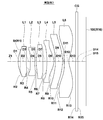
- FIG. 1 is a lens cross-sectional view illustrating a first configuration example of an imaging lens according to an embodiment of the present invention and corresponding to Example 1.
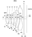
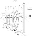
- FIG. FIG. 2 is a lens cross-sectional view illustrating a second configuration example of an imaging lens according to an embodiment of the present invention and corresponding to Example 2; 3 is a lens cross-sectional view illustrating a third configuration example of an imaging lens according to an embodiment of the present invention and corresponding to Example 3.
- FIG. 4 is a lens cross-sectional view illustrating a fourth configuration example of an imaging lens according to an embodiment of the present invention and corresponding to Example 4;
- FIG. 5 is a lens cross-sectional view illustrating a fifth configuration example of an imaging lens according to an embodiment of the present invention and corresponding to Example 5.
- FIG. 1 is a lens cross-sectional view illustrating a first configuration example of an imaging lens according to an embodiment of the present invention and corresponding to Example 1.
- FIG. FIG. 2 is a lens cross-sectional view illustrating a second configuration
- FIG. 6 is a lens cross-sectional view illustrating a sixth configuration example of an imaging lens according to an embodiment of the present invention and corresponding to Example 6.
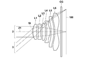
- FIG. FIG. 2 is an optical path diagram of the imaging lens shown in FIG. 1.
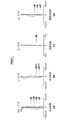
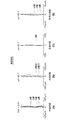
- It is an aberration diagram which shows the various aberrations of the imaging lens which concerns on Example 1 of this invention, (A) shows spherical aberration, (B) shows astigmatism, (C) shows distortion aberration, (D) shows lateral chromatic aberration.
- FIG. 1 shows a first configuration example of an imaging lens according to the first embodiment of the present invention.
- This configuration example corresponds to the lens configuration of a first numerical example (Tables 1 and 2) described later.
- FIG. 7 is an optical path diagram of the imaging lens shown in FIG. 1, and shows the optical paths of the axial light beam 2 and the light beam 3 with the maximum field angle from an object point at an infinite distance.
- An imaging lens includes various imaging devices using an image sensor such as a CCD or a CMOS, particularly a relatively small portable terminal device such as a digital still camera, a mobile phone with a camera, a smartphone, and a tablet type. It is suitable for use in terminals and PDAs.
- an image sensor such as a CCD or a CMOS
- a relatively small portable terminal device such as a digital still camera, a mobile phone with a camera, a smartphone, and a tablet type. It is suitable for use in terminals and PDAs.
- FIG. 14 shows an overview of a mobile phone terminal that is the imaging apparatus 1 according to the embodiment of the present invention.
- An imaging device 1 according to an embodiment of the present invention includes an imaging lens L according to the present embodiment and an imaging element 100 such as a CCD that outputs an imaging signal corresponding to an optical image formed by the imaging lens L (see FIG. 1).
- the image sensor 100 is disposed on the imaging surface (image surface R16) of the imaging lens L.
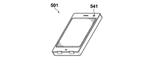
- FIG. 15 shows an overview of a smartphone that is the imaging device 501 according to the embodiment of the present invention.
- An image pickup apparatus 501 according to the embodiment of the present invention includes an image pickup lens L according to this embodiment and an image pickup device 100 such as a CCD that outputs an image pickup signal corresponding to an optical image formed by the image pickup lens L (see FIG. 1)).
- the imaging lens L includes a first lens L1, a second lens L2, a third lens L3, a fourth lens L4, and a first lens in order from the object side along the optical axis Z1.
- 5 lens L5 and 6th lens L6 are provided.
- Various optical members CG may be arranged between the sixth lens L6 and the image sensor 100 according to the configuration on the camera side where the lens is mounted.
- a parallel plate-like optical member such as a cover glass for protecting the imaging surface or an infrared cut filter may be disposed.
- a parallel plate-like cover glass coated with a coating having a filter effect such as an infrared cut filter or an ND filter may be used.
- the sixth lens L6 may be coated to have the same effect as the optical member CG. Thereby, the number of parts can be reduced and the overall length can be shortened.
- the imaging lens L preferably further includes an aperture stop St disposed on the object side of the object side surface of the second lens L2.
- an imaging surface imaging device
- the aperture stop St is disposed on the object side with respect to the image side surface of the first lens L1 in the optical axis direction.
- the aperture stop St As described above, by arranging the aperture stop St closer to the object side than the image side surface of the first lens L1, the incident angle of the light beam passing through the optical system to the imaging surface (imaging device) is more preferably increased. Can be suppressed, and higher optical performance can be realized.
- the aperture stop St is “arranged on the object side from the object side surface of the second lens” means that the position of the aperture stop in the optical axis direction is between the axial marginal ray and the object side surface of the second lens L2. It means that it is at the same position as the intersection or closer to the object side, and the aperture stop St is “located on the object side from the image side surface of the first lens” means that the position of the aperture stop in the optical axis direction is the axis It means that it is at the same position as the intersection of the upper marginal ray and the image side surface of the first lens L1 or on the object side.
- the aperture stop St is disposed on the image side with respect to the surface vertex of the object side surface of the first lens L1.
- the aperture stop St is the first lens L1. You may arrange
- the aperture stop St is closer to the image side than the surface vertex of the object side surface of the first lens L1.
- the incident angle of the light beam passing through the optical system on the imaging surface (imaging device) becomes larger at the periphery of the imaging region. Can be more suitably suppressed.
- the aperture stop St shown in FIGS. 1 to 7 does not necessarily indicate the size or shape, but indicates the position on the optical axis Z.
- the first lens L1 has a positive refractive power in the vicinity of the optical axis, and has a convex surface facing the object side in the vicinity of the optical axis.
- the overall length can be suitably shortened.
- the first lens L1 since the first lens L1 has a convex surface facing the object side, the most object-side surface of the lens system has a convex shape toward the object side.
- the total length can be suitably shortened.
- the first lens L1 is preferably a meniscus lens having a convex surface facing the object side in the vicinity of the optical axis. In this case, it is further advantageous for shortening the overall length.
- the second lens L2 has a negative refractive power in the vicinity of the optical axis.
- the second lens L2 preferably has a concave surface facing the image side in the vicinity of the optical axis. In this case, it is advantageous for shortening the overall length.
- the second lens L2 is preferably a meniscus lens in the vicinity of the optical axis. In this case, the second lens L2 is further advantageous for shortening the overall length and is advantageous for widening the angle.
- the overall length can be shortened more favorably, and the spherical aberration differs for each wavelength with respect to light beams having different wavelengths. It can suppress becoming a thing.
- the third lens L3 is a meniscus lens having a positive refractive power in the vicinity of the optical axis and having a convex surface facing the object side in the vicinity of the optical axis.
- the third lens L3 is a meniscus lens having a convex surface facing the object side in the vicinity of the optical axis, which is advantageous for shortening the overall length and for widening the angle.
- the concave lens has an object side surface on the object side of the third lens L3. Since the convex surface of the surface has a corresponding shape, the distance on the optical axis between the second lens L2 and the third lens L3 can be shortened, and the overall length can be further shortened.
- the fourth lens L4 has a positive refractive power in the vicinity of the optical axis. This is advantageous for shortening the overall length.
- the fourth lens L4 is preferably a meniscus lens in the vicinity of the optical axis. In this case, astigmatism can be easily corrected.
- the fourth lens L4 is a meniscus lens having a concave surface on the object side, astigmatism can be corrected more easily.
- the fifth lens L5 has a negative refractive power in the vicinity of the optical axis. This is advantageous for shortening the overall length.
- the fifth lens L5 has a concave surface facing the object side in the vicinity of the optical axis.
- the fifth lens L5 having a concave surface facing the object side in the vicinity of the optical axis facilitates correction of astigmatism and is advantageous for widening the angle.
- the fifth lens L5 is preferably a meniscus lens having a concave surface facing the object side in the vicinity of the optical axis. In this case, astigmatism can be corrected more easily.
- the sixth lens L6 has a negative refractive power in the vicinity of the optical axis. This is advantageous for shortening the overall length.
- the sixth lens L6 has a concave surface facing the image side in the vicinity of the optical axis.
- the sixth lens L6 is configured to have a concave surface facing the image side in the vicinity of the optical axis, so that the overall length can be suitably shortened.
- the sixth lens L6 is preferably a meniscus lens having a concave surface facing the image side in the vicinity of the optical axis. In this case, it is advantageous for shortening the overall length and correcting field curvature.
- the image-side surface of the sixth lens L6 has an aspheric shape that is concave in the vicinity of the optical axis and convex in the periphery. That is, the image side surface of the sixth lens L6 has an aspheric shape having an inflection point within the effective diameter. “Having an inflection point” on the image side surface of the sixth lens L6 means that when considering a curve formed of the image side surface of the sixth lens L6 in the lens cross section including the optical axis Z1 within the effective diameter, It means that this curve has a point where the convex shape changes to a concave shape (or from a concave shape to a convex shape).
- the peripheral part here means a radial direction outer side from 60% of the maximum effective radius.
- the surface on the image side of the sixth lens L6 has a concave shape in the vicinity of the optical axis and an aspherical shape that has a convex shape in the peripheral portion, so that the light beam passing through the optical system is connected particularly in the peripheral portion of the imaging region. It is possible to suppress an increase in the incident angle to the image plane (imaging element), and it is possible to suppress a decrease in light receiving efficiency in the periphery of the imaging region while realizing a reduction in the total length.
- the imaging lens L is arranged in order from the object side, and has a first lens L1 having a positive refractive power with a convex surface facing the object side, a second lens L2 having a negative refractive power, and a positive refractive power.
- the overall length can be suitably shortened while having a wide angle.
- the fifth lens L5 and the sixth lens L6 having negative refractive power adjacent to the image side of the fourth lens L4 the rear principal point of the entire lens system is positioned closer to the object side. And the overall length can be shortened satisfactorily.
- an aspherical surface for at least one surface of each of the first lens L1 to the sixth lens L6 for high performance.
- the first lens L1 to the sixth lens L6 constituting the imaging lens L are not a cemented lens but a single lens. Since the number of surfaces is increased and the number of aspheric surfaces can be increased as compared with the case where any one of the first lens L1 to the sixth lens L6 is a cemented lens, the degree of design freedom of each lens is high. This is because the overall length can be preferably shortened.
- the lens configurations of the first lens L1 to the sixth lens L6 of the imaging lens L are set so that the total angle of view is 60 degrees or more as in the example illustrated in FIG.
- the imaging lens L can be suitably applied to a mobile phone terminal or the like where there are many photographing opportunities.
- the imaging lens L satisfies the following conditional expression (1). 1.54 ⁇ f / f4 ⁇ 3 (1)
- f Focal length of the entire system
- f4 The focal length of the fourth lens.
- the imaging lens L satisfies any one of the following conditional expressions or any combination. It is preferable that the satisfying conditional expression is appropriately selected according to the items required for the imaging lens L.
- f focal length of the entire system
- f1 focal length of the first lens
- f23456 composite focal length from the second lens to the sixth lens
- R1f paraxial radius of curvature of the object side surface of the first lens
- R1r of the first lens The paraxial radius of curvature of the image side surface.
- Conditional expression (1) defines a preferable numerical range of the ratio of the focal length f of the entire system to the focal length f4 of the fourth lens L4.
- conditional expression (1) By configuring so as to satisfy the conditional expression (1), it is possible to satisfactorily correct spherical aberration while reducing the length of the entire lens system. In order to enhance this effect, it is more preferable to satisfy the conditional expression (1-1), and it is even more preferable to satisfy the conditional expression (1-2). 1.55 ⁇ f / f4 ⁇ 2.5 (1-1) 1.55 ⁇ f / f4 ⁇ 2.2 (1-2)
- Conditional expression (2) defines a preferable numerical range of the ratio of the focal length f of the entire system to the focal length f1 of the first lens L1.
- conditional expression (2) By configuring so as to satisfy the conditional expression (2), it is possible to suitably shorten the length of the entire lens system while favorably correcting spherical aberration and low field angle astigmatism. In order to enhance this effect, it is more preferable to satisfy the conditional expression (2-1), and it is even more preferable to satisfy the conditional expression (2-2). 0.6 ⁇ f / f1 ⁇ 0.95 (2-1) 0.65 ⁇ f / f1 ⁇ 0.9 (2-2)
- Conditional expression (3) defines a preferable numerical range of the ratio of the focal length f of the entire system to the combined focal length from the second lens L2 to the sixth lens L6. That is, conditional expression (3) defines a preferable numerical range of the ratio of the refractive power of the combined optical system in which the lenses other than the first lens L1 are combined with the refractive power of the entire system.
- conditional expression (3) defines a preferable numerical range of the ratio of the refractive power of the combined optical system in which the lenses other than the first lens L1 are combined with the refractive power of the entire system.
- conditional expression (3) By configuring so as to satisfy the conditional expression (3), it is possible to correct the astigmatism satisfactorily and shorten the length of the entire lens system while widening the angle. In order to enhance this effect, it is more preferable to satisfy the conditional expression (3-1), and it is even more preferable to satisfy the conditional expression (3-2). -0.2 ⁇ f / f23456 ⁇ 0.3 (3-1) -0.15 ⁇ f / f23456 ⁇ 0.25 (3-2)
- Conditional expression (4) defines a preferable numerical range regarding the paraxial curvature radius R1f of the object side surface of the first lens L1 and the paraxial curvature radius R1r of the image side surface of the first lens L1.
- the curvature radius of the image-side surface of the first lens L1 is the first. It is possible to prevent the lens L1 from becoming too small with respect to the radius of curvature of the object side surface, which is advantageous for shortening the overall length.
- the paraxial curvature radius of the image side surface of the first lens L1 is set. Can be prevented from becoming too large with respect to the paraxial radius of curvature of the object-side surface of the first lens L1, and spherical aberration and astigmatism can be favorably corrected.
- conditional expression (4) By configuring so as to satisfy the conditional expression (4), it is possible to favorably correct the spherical aberration and astigmatism while appropriately shortening the entire length, and to widen the angle. In order to enhance this effect, it is more preferable to satisfy the conditional expression (4-1), and it is even more preferable to satisfy the conditional expression (4-2). ⁇ 0.65 ⁇ (R1f ⁇ R1r) / (R1f + R1r) ⁇ 0.1 (4-1) ⁇ 0.62 ⁇ (R1f ⁇ R1r) / (R1f + R1r) ⁇ 0.2 (4-2)
- Tables 1 and 2 below show specific lens data corresponding to the configuration of the imaging lens shown in FIG. Table 1 shows the basic lens data, and Table 2 shows data related to the aspherical surface.
- the surface of the aperture stop St is the first and the most object side lens surface (the object side of the first lens L1 is the object side).
- the number of the i-th surface is indicated by the number of the second surface, and the number is sequentially increased toward the image side.
- the value (mm) of the curvature radius of the i-th surface is shown, which corresponds to the symbol Ri attached in FIG.
- the column of the surface interval Di indicates the interval (mm) on the optical axis between the i-th surface Si and the i + 1-th surface Si + 1 from the object side.
- the value of the refractive index for the d-line (587.56 nm) of the j-th optical element from the object side is shown.
- the column of ⁇ dj shows the Abbe number value for the d-line of the j-th optical element from the object side.
- the sign of the radius of curvature is positive when the surface shape has a convex surface facing the object side, and negative when the surface shape has a convex surface facing the image side.
- the focal length f (mm) of the entire system, the back focus Bf (mm), the F number Fno., The total angle of view 2 ⁇ (°), and the total lens length are shown as various data.
- TL (mm) is shown respectively.
- the back focus Bf represents a value converted into air.
- the total lens length TL is a distance on the optical axis from the object-side surface of the first lens L1 to the image plane, and represents a value obtained by converting the back focus Bf into air.
- both surfaces of the first lens L1 to the sixth lens L6 are all aspherical.
- the basic lens data in Table 1 shows the numerical value of the radius of curvature near the optical axis (paraxial radius of curvature) as the radius of curvature of these aspheric surfaces.
- Table 2 shows aspherical data in the imaging lens of Example 1.
- E indicates that the subsequent numerical value is a “power exponent” with a base of 10
- the numerical value represented by an exponential function with the base of 10 is Indicates that the value before “E” is multiplied.
- “1.0E-02” indicates “1.0 ⁇ 10 ⁇ 2 ”.
- Z represents the length (mm) of a perpendicular line drawn from a point on the aspheric surface at a height h from the optical axis to a plane perpendicular to the optical axis in contact with the aspherical vertex.
- Z C ⁇ h 2 / ⁇ 1+ (1 ⁇ K ⁇ C 2 ⁇ h 2 ) 1/2 ⁇ + ⁇ An ⁇ h n (A)
- Z Depth of aspheric surface (mm)
- h Distance from the optical axis to the lens surface (height) (mm)
- C: Paraxial curvature 1 / R (R: paraxial radius of curvature)
- K aspheric coefficient
- Table 3 and Table 4 show specific lens data corresponding to the configuration of the imaging lens shown in FIG. 2 as Example 2 in the same manner as the imaging lens of Example 1 described above. Similarly, specific lens data corresponding to the configuration of the imaging lens shown in FIGS. 3 to 6 is shown in Tables 5 to 12 as Example 3 to Example 6. In the imaging lenses according to Example 1 to Example 6, both surfaces of the first lens L1 to the sixth lens L6 are all aspherical.
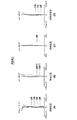
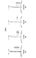
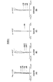
- FIGS. 8A to 8D are diagrams showing spherical aberration, astigmatism, distortion (distortion), and chromatic aberration of magnification (chromatic aberration of magnification) in the imaging lens of Example 1, respectively.
- Each aberration diagram showing spherical aberration, astigmatism, and distortion shows aberrations with the d-line (wavelength 587.56 nm) as the reference wavelength.
- the spherical aberration diagram and the lateral chromatic aberration diagram also show aberrations for the F-line (wavelength 486.1 nm), C-line (wavelength 656.27 nm), and g-line (wavelength 435.83 nm).
- the solid line indicates the sagittal direction (S), and the broken line indicates the tangential direction (T).
- Fno. Indicates the F number, and ⁇ indicates the half angle of view.
- the aberration diagrams shown in FIGS. 8A to 8D to 13A to 13D are all when the object distance is infinite.
- Table 13 shows values relating to the conditional expressions (1) to (4) according to the present invention for each of Examples 1 to 6.
- the imaging lenses of Examples 1 to 6 are the ratio of the total lens length TL to the focal length F of the entire system, while the angle of view is as wide as 80 degrees or more.
- TL / f is in the range of 1.27 to 1.31, and while the overall length is shortened, various aberrations are well corrected and high imaging performance is realized.
- the imaging lens of the present invention is not limited to the above-described embodiments and examples, and various modifications can be made.
- the values of the radius of curvature, the surface interval, the refractive index, the Abbe number, and the aspheric coefficient of each lens component are not limited to the values shown in the above numerical examples, and may take other values.
- the description is made on the assumption that the fixed focus is used, but it is also possible to adopt a configuration in which the focus can be adjusted.
- the entire lens system can be extended, or a part of the lenses can be moved on the optical axis to enable autofocusing.
Landscapes
- Physics & Mathematics (AREA)
- General Physics & Mathematics (AREA)
- Optics & Photonics (AREA)
- Lenses (AREA)
Abstract
L'invention concerne un objectif d'imagerie présentant une longueur totale plus courte tout en réalisant un grand angle et un résolution plus élevée, et un dispositif d'imagerie muni de l'objectif d'imagerie. L'objectif d'imagerie est formé sensiblement de six lentilles comprenant, dans l'ordre en partant du côté objet: une première lentille (L1) dotée d'une vergence positive et une surface convexe orientée vers le côté objet; une deuxième lentille (L2) dotée d'une vergence négative; une troisième lentille (L3) dotée d'une vergence positive et présentant la forme d'un ménisque dont une surface convexe est orientée vers le côté objet; une quatrième lentille (L4) dotée d'une vergence positive; une cinquième lentille (L5) dotée d'une vergence négative et d'une surface concave orientée vers le côté objet; et une sixième lentille (L6) dotée d'une vergence négative et présentant une forme de surface non sphérique caractérisée en ce que la surface du côté image engendre une forme concave au voisinage de l'axe optique et une forme concave dans sa partie périphérique. Une équation conditionnelle (1) pour la distance focale (f) du système entier et la distance focale (f4) de la quatrième lentille, 1,54 < f/f4 < 3, est satisfaite.
Priority Applications (2)
| Application Number | Priority Date | Filing Date | Title |
|---|---|---|---|
| CN201390001146.7U CN205067841U (zh) | 2013-03-26 | 2013-12-26 | 摄影透镜以及具备摄影透镜的摄影装置 |
| US14/863,459 US9709775B2 (en) | 2013-03-26 | 2015-09-24 | Imaging lens and imaging apparatus equipped with the imaging lens |
Applications Claiming Priority (2)
| Application Number | Priority Date | Filing Date | Title |
|---|---|---|---|
| JP2013063612 | 2013-03-26 | ||
| JP2013-063612 | 2013-03-26 |
Related Child Applications (1)
| Application Number | Title | Priority Date | Filing Date |
|---|---|---|---|
| US14/863,459 Continuation US9709775B2 (en) | 2013-03-26 | 2015-09-24 | Imaging lens and imaging apparatus equipped with the imaging lens |
Publications (1)
| Publication Number | Publication Date |
|---|---|
| WO2014155467A1 true WO2014155467A1 (fr) | 2014-10-02 |
Family
ID=51394752
Family Applications (1)
| Application Number | Title | Priority Date | Filing Date |
|---|---|---|---|
| PCT/JP2013/007641 Ceased WO2014155467A1 (fr) | 2013-03-26 | 2013-12-26 | Objectif d'imagerie et dispositif d'imagerie muni de l'objectif d'imagerie |
Country Status (4)
| Country | Link |
|---|---|
| US (1) | US9709775B2 (fr) |
| CN (1) | CN205067841U (fr) |
| TW (1) | TWM479426U (fr) |
| WO (1) | WO2014155467A1 (fr) |
Cited By (10)
| Publication number | Priority date | Publication date | Assignee | Title |
|---|---|---|---|---|
| TWI588525B (zh) * | 2016-01-04 | 2017-06-21 | 玉晶光電股份有限公司 | 光學鏡片組 |
| TWI626487B (zh) * | 2017-03-31 | 2018-06-11 | 大立光電股份有限公司 | 光學影像鏡頭系統組、取像裝置及電子裝置 |
| TWI627466B (zh) * | 2017-02-22 | 2018-06-21 | 玉晶光電股份有限公司 | 光學鏡片組 |
| US10007092B2 (en) | 2016-01-04 | 2018-06-26 | Genius Electronic Optical (Xiamen) Co., Ltd. | Optical lens assembly |
| TWI641889B (zh) * | 2017-01-05 | 2018-11-21 | 先進光電科技股份有限公司 | 光學成像系統 |
| TWI641890B (zh) * | 2017-01-05 | 2018-11-21 | 先進光電科技股份有限公司 | 光學成像系統 |
| TWI641891B (zh) * | 2017-01-05 | 2018-11-21 | 先進光電科技股份有限公司 | 光學成像系統 |
| TWI660194B (zh) * | 2014-12-05 | 2019-05-21 | 南韓商三星電機股份有限公司 | 光學系統 |
| TWI673534B (zh) * | 2018-04-03 | 2019-10-01 | 玉晶光電股份有限公司 | 光學成像鏡頭 |
| US10921568B2 (en) | 2013-07-25 | 2021-02-16 | Largan Precision Co., Ltd. | Image lens assembly and image capturing device |
Families Citing this family (14)
| Publication number | Priority date | Publication date | Assignee | Title |
|---|---|---|---|---|
| WO2014155466A1 (fr) * | 2013-03-26 | 2014-10-02 | 富士フイルム株式会社 | Lentille d'imagerie et dispositif d'imagerie equipe de la lentille d'imagerie |
| KR102180476B1 (ko) * | 2013-12-17 | 2020-11-18 | 삼성전자주식회사 | 촬상 렌즈 시스템 및 이를 채용한 촬상 장치 |
| JP6226376B2 (ja) | 2013-12-25 | 2017-11-08 | カンタツ株式会社 | 撮像レンズ |
| JP2015194528A (ja) * | 2014-03-31 | 2015-11-05 | 富士フイルム株式会社 | 撮像レンズおよび撮像レンズを備えた撮像装置 |
| TWI522643B (zh) | 2014-06-11 | 2016-02-21 | 先進光電科技股份有限公司 | 光學成像系統 |
| JP6319765B2 (ja) * | 2014-07-02 | 2018-05-09 | 株式会社オプトロジック | 撮像レンズ |
| CN104820275B (zh) | 2015-01-23 | 2017-07-11 | 玉晶光电(厦门)有限公司 | 可携式电子装置与其光学成像镜头 |
| US10228542B2 (en) * | 2016-02-12 | 2019-03-12 | Newmax Technology Co., Ltd. | Four-piece infrared single wavelength lens system |
| JP6403711B2 (ja) | 2016-04-04 | 2018-10-10 | カンタツ株式会社 | 撮像レンズ |
| US10302909B2 (en) * | 2016-10-21 | 2019-05-28 | Newmax Technology Co., Ltd. | Six-piece optical lens system |
| CN106371196B (zh) * | 2016-12-01 | 2019-01-08 | 广东弘景光电科技股份有限公司 | 大光圈超广角高像素短总长光学系统及其应用的镜头 |
| KR101956704B1 (ko) | 2016-12-20 | 2019-03-11 | 삼성전기주식회사 | 촬상 광학계 |
| JP6374629B1 (ja) * | 2018-03-22 | 2018-08-15 | エーエーシーアコースティックテクノロジーズ(シンセン)カンパニーリミテッドAAC Acoustic Technologies(Shenzhen)Co., Ltd | 撮像レンズ |
| CN111505796B (zh) * | 2019-01-31 | 2022-05-03 | 信泰光学(深圳)有限公司 | 光学镜头 |
Citations (2)
| Publication number | Priority date | Publication date | Assignee | Title |
|---|---|---|---|---|
| TW201305595A (zh) * | 2012-10-22 | 2013-02-01 | Largan Precision Co Ltd | 影像擷取光學鏡片系統 |
| JP2014013293A (ja) * | 2012-07-04 | 2014-01-23 | Ricoh Co Ltd | 画像読取レンズ、画像読取装置及び画像形成装置 |
Family Cites Families (2)
| Publication number | Priority date | Publication date | Assignee | Title |
|---|---|---|---|---|
| KR101499969B1 (ko) | 2008-10-10 | 2015-03-18 | 엘지이노텍 주식회사 | 촬상 렌즈 및 이를 포함하는 카메라 모듈 |
| JP2015187699A (ja) * | 2014-03-11 | 2015-10-29 | 富士フイルム株式会社 | 撮像レンズおよび撮像レンズを備えた撮像装置 |
-
2013
- 2013-12-26 WO PCT/JP2013/007641 patent/WO2014155467A1/fr not_active Ceased
- 2013-12-26 CN CN201390001146.7U patent/CN205067841U/zh not_active Expired - Lifetime
-
2014
- 2014-01-15 TW TW103200790U patent/TWM479426U/zh not_active IP Right Cessation
-
2015
- 2015-09-24 US US14/863,459 patent/US9709775B2/en active Active
Patent Citations (2)
| Publication number | Priority date | Publication date | Assignee | Title |
|---|---|---|---|---|
| JP2014013293A (ja) * | 2012-07-04 | 2014-01-23 | Ricoh Co Ltd | 画像読取レンズ、画像読取装置及び画像形成装置 |
| TW201305595A (zh) * | 2012-10-22 | 2013-02-01 | Largan Precision Co Ltd | 影像擷取光學鏡片系統 |
Cited By (16)
| Publication number | Priority date | Publication date | Assignee | Title |
|---|---|---|---|---|
| US12050306B2 (en) | 2013-07-25 | 2024-07-30 | Largan Precision Co., Ltd. | Image lens assembly and image capturing device |
| US10921568B2 (en) | 2013-07-25 | 2021-02-16 | Largan Precision Co., Ltd. | Image lens assembly and image capturing device |
| US10838168B2 (en) | 2014-12-05 | 2020-11-17 | Samsung Electro-Mechanics Co., Ltd. | Optical system |
| US12228794B2 (en) | 2014-12-05 | 2025-02-18 | Samsung Electro-Mechanics Co., Ltd. | Optical system |
| US11921352B2 (en) | 2014-12-05 | 2024-03-05 | Samsung Electro-Mechanics Co., Ltd. | Optical system |
| TWI660194B (zh) * | 2014-12-05 | 2019-05-21 | 南韓商三星電機股份有限公司 | 光學系統 |
| US10007092B2 (en) | 2016-01-04 | 2018-06-26 | Genius Electronic Optical (Xiamen) Co., Ltd. | Optical lens assembly |
| TWI588525B (zh) * | 2016-01-04 | 2017-06-21 | 玉晶光電股份有限公司 | 光學鏡片組 |
| TWI641889B (zh) * | 2017-01-05 | 2018-11-21 | 先進光電科技股份有限公司 | 光學成像系統 |
| TWI641891B (zh) * | 2017-01-05 | 2018-11-21 | 先進光電科技股份有限公司 | 光學成像系統 |
| TWI641890B (zh) * | 2017-01-05 | 2018-11-21 | 先進光電科技股份有限公司 | 光學成像系統 |
| TWI627466B (zh) * | 2017-02-22 | 2018-06-21 | 玉晶光電股份有限公司 | 光學鏡片組 |
| US10545315B2 (en) | 2017-03-31 | 2020-01-28 | Largan Precision Co., Ltd. | Optical imaging lens system, image capturing unit and electronic device |
| US12105353B2 (en) | 2017-03-31 | 2024-10-01 | Largan Precision Co., Ltd. | Optical imaging lens system, image capturing unit and electronic device |
| TWI626487B (zh) * | 2017-03-31 | 2018-06-11 | 大立光電股份有限公司 | 光學影像鏡頭系統組、取像裝置及電子裝置 |
| TWI673534B (zh) * | 2018-04-03 | 2019-10-01 | 玉晶光電股份有限公司 | 光學成像鏡頭 |
Also Published As
| Publication number | Publication date |
|---|---|
| CN205067841U (zh) | 2016-03-02 |
| US9709775B2 (en) | 2017-07-18 |
| US20160011405A1 (en) | 2016-01-14 |
| TWM479426U (zh) | 2014-06-01 |
Similar Documents
| Publication | Publication Date | Title |
|---|---|---|
| JP6000179B2 (ja) | 撮像レンズおよび撮像レンズを備えた撮像装置 | |
| JP5886230B2 (ja) | 撮像レンズおよび撮像レンズを備えた撮像装置 | |
| JP5827688B2 (ja) | 撮像レンズおよび撮像レンズを備えた撮像装置 | |
| JP5735712B2 (ja) | 撮像レンズおよび撮像レンズを備えた撮像装置 | |
| JP5911819B2 (ja) | 撮像レンズおよび撮像レンズを備えた撮像装置 | |
| JP5687390B2 (ja) | 撮像レンズおよび撮像レンズを備えた撮像装置 | |
| JP5785324B2 (ja) | 撮像レンズおよび撮像レンズを備えた撮像装置 | |
| JP5706584B2 (ja) | 撮像レンズおよび撮像レンズを備えた撮像装置 | |
| JP5937035B2 (ja) | 撮像レンズおよび撮像レンズを備えた撮像装置 | |
| WO2014155467A1 (fr) | Objectif d'imagerie et dispositif d'imagerie muni de l'objectif d'imagerie | |
| JP2015022145A (ja) | 撮像レンズおよび撮像レンズを備えた撮像装置 | |
| WO2014155466A1 (fr) | Lentille d'imagerie et dispositif d'imagerie equipe de la lentille d'imagerie | |
| JP2014240918A (ja) | 撮像レンズおよび撮像レンズを備えた撮像装置 | |
| JP6150317B2 (ja) | 撮像レンズおよび撮像レンズを備えた撮像装置 | |
| JP2014115456A (ja) | 撮像レンズおよび撮像レンズを備えた撮像装置 | |
| JP2014209163A (ja) | 撮像レンズおよび撮像レンズを備えた撮像装置 | |
| JP2016095460A (ja) | 撮像レンズおよび撮像レンズを備えた撮像装置 | |
| JP2016114803A (ja) | 撮像レンズおよび撮像レンズを備えた撮像装置 | |
| JP2015141267A (ja) | 撮像レンズおよび撮像レンズを備えた撮像装置 | |
| JP5917431B2 (ja) | 撮像レンズおよび撮像レンズを備えた撮像装置 | |
| JP2015102673A (ja) | 撮像レンズおよび撮像レンズを備えた撮像装置 | |
| JP5727679B2 (ja) | 撮像レンズおよび撮像レンズを備えた撮像装置 | |
| JP2015079164A (ja) | 撮像レンズおよび撮像レンズを備えた撮像装置 | |
| JP2015169888A (ja) | 撮像レンズおよび撮像レンズを備えた撮像装置 | |
| JP5722507B2 (ja) | 撮像レンズおよび撮像レンズを備えた撮像装置 |
Legal Events
| Date | Code | Title | Description |
|---|---|---|---|
| WWE | Wipo information: entry into national phase |
Ref document number: 201390001146.7 Country of ref document: CN |
|
| 121 | Ep: the epo has been informed by wipo that ep was designated in this application |
Ref document number: 13879955 Country of ref document: EP Kind code of ref document: A1 |
|
| NENP | Non-entry into the national phase |
Ref country code: DE |
|
| 122 | Ep: pct application non-entry in european phase |
Ref document number: 13879955 Country of ref document: EP Kind code of ref document: A1 |
|
| NENP | Non-entry into the national phase |
Ref country code: JP |