WO2014155607A1 - Seringue - Google Patents
Seringue Download PDFInfo
- Publication number
- WO2014155607A1 WO2014155607A1 PCT/JP2013/059267 JP2013059267W WO2014155607A1 WO 2014155607 A1 WO2014155607 A1 WO 2014155607A1 JP 2013059267 W JP2013059267 W JP 2013059267W WO 2014155607 A1 WO2014155607 A1 WO 2014155607A1
- Authority
- WO
- WIPO (PCT)
- Prior art keywords
- diameter
- annular
- main body
- gasket
- distal end
- Prior art date
- Legal status (The legal status is an assumption and is not a legal conclusion. Google has not performed a legal analysis and makes no representation as to the accuracy of the status listed.)
- Ceased
Links
Images





Classifications
-
- A—HUMAN NECESSITIES
- A61—MEDICAL OR VETERINARY SCIENCE; HYGIENE
- A61M—DEVICES FOR INTRODUCING MEDIA INTO, OR ONTO, THE BODY; DEVICES FOR TRANSDUCING BODY MEDIA OR FOR TAKING MEDIA FROM THE BODY; DEVICES FOR PRODUCING OR ENDING SLEEP OR STUPOR
- A61M5/00—Devices for bringing media into the body in a subcutaneous, intra-vascular or intramuscular way; Accessories therefor, e.g. filling or cleaning devices, arm-rests
- A61M5/178—Syringes
- A61M5/31—Details
- A61M5/315—Pistons; Piston-rods; Guiding, blocking or restricting the movement of the rod or piston; Appliances on the rod for facilitating dosing ; Dosing mechanisms
- A61M5/31511—Piston or piston-rod constructions, e.g. connection of piston with piston-rod
- A61M5/31513—Piston constructions to improve sealing or sliding
-
- A—HUMAN NECESSITIES
- A61—MEDICAL OR VETERINARY SCIENCE; HYGIENE
- A61M—DEVICES FOR INTRODUCING MEDIA INTO, OR ONTO, THE BODY; DEVICES FOR TRANSDUCING BODY MEDIA OR FOR TAKING MEDIA FROM THE BODY; DEVICES FOR PRODUCING OR ENDING SLEEP OR STUPOR
- A61M5/00—Devices for bringing media into the body in a subcutaneous, intra-vascular or intramuscular way; Accessories therefor, e.g. filling or cleaning devices, arm-rests
- A61M5/178—Syringes
- A61M5/31—Details
- A61M2005/3103—Leak prevention means for distal end of syringes, i.e. syringe end for mounting a needle
- A61M2005/3104—Caps for syringes without needle
-
- A—HUMAN NECESSITIES
- A61—MEDICAL OR VETERINARY SCIENCE; HYGIENE
- A61M—DEVICES FOR INTRODUCING MEDIA INTO, OR ONTO, THE BODY; DEVICES FOR TRANSDUCING BODY MEDIA OR FOR TAKING MEDIA FROM THE BODY; DEVICES FOR PRODUCING OR ENDING SLEEP OR STUPOR
- A61M5/00—Devices for bringing media into the body in a subcutaneous, intra-vascular or intramuscular way; Accessories therefor, e.g. filling or cleaning devices, arm-rests
- A61M5/007—Devices for bringing media into the body in a subcutaneous, intra-vascular or intramuscular way; Accessories therefor, e.g. filling or cleaning devices, arm-rests for contrast media
-
- A—HUMAN NECESSITIES
- A61—MEDICAL OR VETERINARY SCIENCE; HYGIENE
- A61M—DEVICES FOR INTRODUCING MEDIA INTO, OR ONTO, THE BODY; DEVICES FOR TRANSDUCING BODY MEDIA OR FOR TAKING MEDIA FROM THE BODY; DEVICES FOR PRODUCING OR ENDING SLEEP OR STUPOR
- A61M5/00—Devices for bringing media into the body in a subcutaneous, intra-vascular or intramuscular way; Accessories therefor, e.g. filling or cleaning devices, arm-rests
- A61M5/178—Syringes
- A61M5/31—Details
- A61M5/315—Pistons; Piston-rods; Guiding, blocking or restricting the movement of the rod or piston; Appliances on the rod for facilitating dosing ; Dosing mechanisms
- A61M5/31511—Piston or piston-rod constructions, e.g. connection of piston with piston-rod
- A61M5/31515—Connection of piston with piston rod
Definitions
- the present invention relates to a syringe.
- the syringe is generally composed of an outer cylinder, a gasket that can slide in the outer cylinder, and a plunger that moves the gasket.
- conventional gaskets made of an elastic material such as vulcanized rubber or thermoplastic elastomer are widely used.
- Such a gasket is required to improve the adhesion with the inner peripheral surface of the outer cylinder and prevent liquid leakage and air inflow. Therefore, the gasket is configured such that a plurality of ring-shaped convex portions are provided on the outer peripheral surface thereof, and these convex portions are elastically deformed and slide while being in close contact with the inner surface of the outer cylinder.
- Patent Document 1 Japanese Utility Model Publication No. 3134991
- the gasket 1 made of synthetic rubber in Patent Document 1 is inserted into a syringe barrel made of synthetic resin in which silicone oil is applied to the inner peripheral surface.
- the outer peripheral surface 2a of the main body 2 is provided with three rows of protrusions 3a to 3c that are slidably contacted with the inner peripheral surface of the syringe outer cylinder and are arranged in parallel in the axial direction with a space therebetween.
- a coating layer 4 formed by applying reactive silicone oil to the outer surface of the part and heating it under water vapor, and a protrusion provided on the base end side of the outer peripheral surface 2a of the main body 2 on the base end side.
- the extending portion 5 is provided extending from the strip portion 3c, and the diameter D3 of the extending portion 5 is larger than the outer diameter D1 of the lower end portion of the protruding portion, and is larger than the outer diameter D2 of the top portion of the protruding portion 3. It is formed small.
- an object of the present invention is to provide a syringe having a low sliding resistance and a small residual liquid in the syringe when the gasket is pushed in until it comes into contact with the innermost surface of the outermost part.
- the syringe which achieves the above object is as follows.
- An outer portion having a cylindrical main body portion having an opening formed at the base end, a nozzle portion having a diameter smaller than that of the main body portion, and a tapered shoulder portion connecting the main body portion and the nozzle portion.
- a syringe having a cylinder and a gasket that is housed in the main body of the outer cylinder and is slidable in a liquid-tight state in the main body, wherein the gasket has an inner shape of the shoulder at the tip At least a first annular rib formed on the outer peripheral portion and positioned on the distal end side, and a second annular rib positioned on the proximal end side from the first annular rib.
- the first annular rib includes a maximum outer diameter portion, and a reduced diameter annular portion that is curved so that an outer diameter decreases from the maximum outer diameter portion toward the distal end surface, and the reduced diameter annular portion There is a recess and a step between the annular tip of the part and the annular base end of the tip surface.
- the gasket is in a state where the outer diameter of the maximum outer diameter portion is larger than the inner diameter of the main body portion in a state before the outer cylinder is inserted into the main body portion.
- the outer diameter of the tip of the diameter annular portion is a syringe smaller than the inner diameter of the main body portion.
- FIG. 1 is a front view of an embodiment in which the syringe of the present invention is applied to a prefilled syringe.
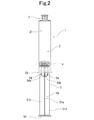
- FIG. 2 is a right side view of the syringe shown in FIG. 3 is a cross-sectional view taken along the line AA in FIG.
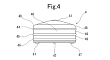
- FIG. 4 is an enlarged front view of a gasket used in the syringe shown in FIG.
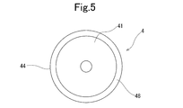
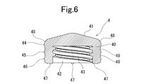
- FIG. 5 is a plan view of the gasket shown in FIG. 6 is a longitudinal sectional view of the gasket shown in FIG.
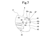
- FIG. 7 is an explanatory diagram for explaining a configuration in the vicinity of the first annular rib of the gasket shown in FIG. 4.
- FIG. 8 is a perspective view of the gasket shown in FIG. 4 as viewed from the front end side.
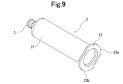
- FIG. 9 is a perspective view seen from the rear end side of the outer cylinder used in the syringe shown in FIG.
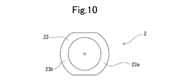
- FIG. 10 is an enlarged bottom view of the outer cylinder used in the syringe shown in FIG.
- FIG. 11 is an enlarged longitudinal sectional view of an outer cylinder used in the syringe shown in FIG.
- FIG. 12 is an enlarged cross-sectional view of the distal end portion of the outer cylinder shown in FIG.
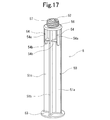
- FIG. 17 is an enlarged perspective view of the plunger shown in FIG.
- the syringe of the present invention will be described with reference to an example applied to a prefilled syringe.
- the syringe of the present invention connects a cylindrical main body 21 having an opening at the proximal end, a nozzle 24 provided at the distal end and having a diameter smaller than that of the main body 21, and the main body 21 and the nozzle 24.
- the outer cylinder 2 having a tapered shoulder 27 and the gasket 4 that is accommodated in the main body 21 of the outer cylinder 2 and that can slide in the liquid-tight state in the main body 21.
- the gasket 4 has a tapered tip end surface 41 substantially matching the shape of the inner surface 27a of the shoulder 27 at the tip, and a first annular rib (tip tip side annular rib) formed on the outer periphery and positioned on the tip end side. ) 44 and at least a second annular rib (base-end-side annular rib) 45 located on the proximal end side with respect to the first annular rib 44.
- the first annular rib 44 includes a maximum outer diameter portion, and a reduced diameter annular portion that is curved so that the outer diameter decreases from the maximum outer diameter portion toward the tip surface (in other words, a reduced diameter annular tip portion, an annular arc portion) ) 48 and between the annular tip 48a of the reduced-diameter annular portion 48 and the annular proximal end of the distal end surface 41, there is no recess and a step, and it is smoothly continuous.
- the gasket 4 has an outer diameter D1 of the maximum outer diameter portion of the first annular rib 44 that is larger than an inner diameter D2 of the main body portion 21 of the outer cylinder 2 in a state before being inserted into the main body portion 21 of the outer cylinder 2.
- the outer diameter D3 of the tip 48a of the reduced diameter annular portion 48 is larger than the inner diameter D2 of the main body portion 21.
- the prefilled syringe 1 of this embodiment includes the outer cylinder 2, the sealing member 3 for sealing the nozzle portion 24 of the outer cylinder 2, the slidable gasket 4 housed in the outer cylinder,
- the plunger 5 is attached to or attachable to the rear end of the gasket 4, and the chemical solution 8 is filled in a space formed by the outer cylinder 2, the gasket 4, and the sealing member 3.
- the sealing member 3 is formed by a detachable seal cap 3.
- the prefilled syringe 1 of the present invention comprises a chemical solution 8 filled in a space formed by an outer cylinder 2, a gasket 4, and a seal cap 3 as a sealing member.
- the outer cylinder 2 is a cylindrical body formed of a transparent or translucent material, preferably a material having low oxygen permeability and water vapor permeability.
- the outer cylinder 2 includes a cylindrical main body portion 21 having an opening at the base end, a nozzle portion 22 that is provided at the distal end and has a diameter smaller than that of the main body portion 21, and a taper that connects the main body portion 21 and the nozzle portion 24. And a flange 23 provided on the rear end side of the cylindrical main body 21.
- the cylindrical main body portion 21 is a substantially cylindrical portion that accommodates the gasket 4 in a liquid-tight and slidable manner
- the nozzle portion 24 is a cylindrical portion having a smaller diameter than the cylindrical main body portion 21.
- the shoulder portion 27 is a tapered shoulder portion that rapidly decreases in diameter toward the nozzle portion 24.
- the taper angle of the inner surface 27a of the tapered shoulder 27 is preferably 70 to 80 degrees.
- the flange 23 has an arcuate outer edge formed so as to protrude vertically from the entire periphery of the rear end of the cylindrical main body 21. .
- the flange is in the shape of a donut board with an internal defect.
- the flange has two arcuate outer edge portions 23a and 23b facing each other.
- the nozzle portion 24 is provided at the distal end of the outer cylinder 2, and includes a distal end opening for discharging the chemical solution and the like in the outer cylinder and is tapered toward the distal end. It is formed to reduce the diameter.
- the outer cylinder 2 includes a nozzle portion 24 and a collar 25 formed concentrically.
- the collar 25 is formed in a cylindrical shape concentrically with the nozzle portion 24 so as to surround the nozzle portion 24.
- the collar 25 has an open end, and the inner diameter and the outer diameter of the collar 25 are substantially the same from the proximal end to the distal end.
- the tip end portion of the nozzle portion 24 protrudes from the tip opening of the collar 25, and the nozzle portion 24 and the tip end portion of the collar 25 accommodate the nozzle portion 24 and the collar 25 in the sealing member (seal cap) 3. It is chamfered to make it easier.
- the thread groove (outer cylinder side screwing portion) 26 is formed. Thereby, the outer cylinder 2 and the seal cap 3 are engaged between the collar inner peripheral surface and the nozzle housing portion outer peripheral surface. Further, the thread groove (outer tube side screwing portion) 26 is a portion to which the injection needle (the hub of the injection needle) is attached after the seal cap 3 is removed from the outer tube.
- Examples of the material for forming the outer cylinder 2 include polypropylene, polyethylene, polystyrene, polyamide, polycarbonate, polyvinyl chloride, poly- (4-methylpentene-1), acrylic resin, acrylonitrile-butadiene-styrene copolymer, polyethylene terephthalate.
- Various resins such as polyesters, cyclic polyolefin polymers, and cyclic olefin copolymers are preferable. Among them, resins such as polypropylene, cyclic polyolefin polymers, and cyclic olefin copolymers are preferable because they are easy to mold and have heat resistance.
- a cyclic polyolefin polymer and a cyclic olefin copolymer having high transparency and heat resistance that can withstand autoclave sterilization so that the chemical solution filled inside can be visually confirmed from the outside are particularly preferable as a material for forming the outer cylinder 2. .
- the gasket 4 includes a cylindrical main body 40 and a tapered front end surface 41 extending from the main body 40 in the front end direction.
- a plurality of annular ribs 44, 45, and 46 are provided on the outer peripheral surface of the main body portion 40 (three or two or more in this embodiment as long as liquid tightness and slidability can be satisfied). ) Is formed. These ribs are in liquid-tight contact with the inner surface of the outer cylinder 2.
- the tip surface 41 of the gasket 4 has a shape corresponding to the shape of the tip inner surface of the outer tube 2 so as not to form a gap as much as possible when contacting the inner surface of the outer tube 2.
- the gasket 4 includes a concave portion 42 that is inside the cylindrical main body 40 and extends in the front end direction from the rear end opening.
- the recess 42 can store the tip 52 of the plunger 5.
- a gasket side screwing portion 43 is formed on the inner surface of the recess 42 (the inner surface of the cylindrical main body portion 40).
- the gasket-side screwing portion 43 can be screwed with a plunger-side screwing portion 57 formed on the outer surface of the tip portion 52 formed at the tip portion of the plunger 5.
- the plunger 5 is not detached from the gasket 4 by screwing them together.
- the plunger 5 may be removed and attached at the time of use.
- the gasket 4 is provided with a plurality of ribs 47 on the lower end surface of the cylindrical main body 40.
- the gasket 4 is formed at the tip at a tapered tip end surface 41 that substantially matches the shape of the inner surface 27 a of the shoulder 27 of the outer cylinder 2, and the outer peripheral portion of the main body 40. And a first annular rib (tip-side annular rib) 44 located on the distal end side and a second annular rib (center annular rib) 45 located on the proximal side from the first annular rib 44. . Further, the gasket 4 of this embodiment includes a third annular rib 46 positioned further on the proximal end side than the second annular rib 45. A recess 49 is also formed between the second annular rib 45 and the third annular rib 46.
- the first annular rib 44 has a maximum outer diameter portion and a reduced diameter annular portion 48 that is curved so that the outer diameter decreases from the maximum outer diameter portion toward the distal end surface. Between the annular distal end 48a of 48 and the annular proximal end of the distal end surface 41, there are no recesses and steps, and they are smoothly continuous. As shown in FIG. 7, the first annular rib 44 includes the same outer diameter portion extending in the predetermined long axis direction, and the entire portion is the maximum outer diameter portion. Further, the base end 48b of the reduced diameter annular portion 48 is also the maximum outer diameter portion.
- the gasket 4 has a maximum outer diameter of the first annular rib 44 (and the base end 48 b of the reduced diameter annular portion 48) before being inserted into the main body portion 21 of the outer cylinder 2.
- the outer diameter D1 of the diameter portion is larger than the inner diameter D2 of the main body portion 21 of the outer cylinder 2
- the outer diameter D3 of the tip 48a of the reduced diameter annular portion 48 is smaller than the inner diameter D2 of the main body portion 21.
- the tip side portion of the reduced diameter annular portion is not compressed because it does not contact the inner surface of the outer cylinder main body. Further, since the diameter-reduced annular portion is reduced in diameter toward the distal end side, the degree of compression due to the inner surface of the outer cylinder main body portion becomes lower toward the distal end side of the reduced-diameter annular portion. The deformability of the part is made good, and the sliding resistance, particularly the resistance at the time of the initial movement toward the tip side is reduced.
- the gasket 4 of this embodiment includes an annular recess 49 formed between the first annular rib 44 and the second annular rib 45, and the outer diameter D3 of the tip 48a of the reduced diameter annular portion 48 is an annular recess. 49 is smaller than the outer diameter D4. Furthermore, in the gasket 4 of this embodiment, as shown in FIG. 7, the diameter D5 of the midpoint 48c of the distal end 48a and the base end 48b of the reduced diameter annular portion 48 is smaller than the outer diameter D4 of the annular recess 49. ing.
- the diameter D5 of the midpoint 48c between the distal end 48a of the reduced diameter annular portion 48 and the base end 48b before the insertion into the main body portion 21 of the outer cylinder 2 is the outer cylinder. 2 is smaller than the inner diameter D2 of the main body 21.
- the diameter at the intermediate portion between the distal end 48a and the base end 48b of the reduced diameter annular portion 48 is as follows from the diameter D5 of the midpoint 48c of the distal end 48a of the reduced diameter annular portion 48 and the base end 48b. It has become a big thing.
- the reduced diameter annular portion 48 has an arc whose outer edge in the axial cross section swells outward.
- the radius of the arc Ra on the outer edge of the reduced diameter annular portion 48 is preferably 2.5 to 5 mm.
- the thickness is preferably 3.0 to 4.0 mm.
- the radius of the arc By setting the radius of the arc to 2.5 mm or more, at least a part of the reduced-diameter annular portion remains uncompressed in a state where the gasket 4 is housed in the main body portion 21 of the outer cylinder 2. Further, when the radius of the arc is 5 mm or less, a dead formed between the shoulder portion and the reduced-diameter annular portion when the shoulder portion inner surface 27a of the outer cylinder 2 and the tip end surface 41 of the gasket 4 come into contact with each other. Space can be reduced.
- the tapered shape of the distal end surface 41 is substantially the same as the shape of the inner surface 27 a of the shoulder portion 27.
- the distal end surface 41 is preferably a tapered distal end surface, and the taper angle is preferably 70 to 80 degrees. Thereby, the full length of a syringe (outer cylinder 2) can be shortened.
- the outer diameter D1 of the maximum outer diameter portion (first annular rib 44) of the gasket 4 is preferably 1.02 to 1.07 times the inner diameter D2 of the main body portion 21 of the outer cylinder 2.
- the internal diameter D2 of the main-body part 21 of the outer cylinder 2 is 30 mm or more. Thereby, the internal volume of the outer cylinder 2 can be enlarged and a large amount of chemical
- the maximum outer diameters of the second annular rib 45 and the third annular rib 46 are larger than the inner diameter D2 of the main body portion 21 of the outer cylinder 2, and are stored on the inner surface of the outer cylinder main body portion 21 when stored in the outer cylinder. Touched and compressed.
- the maximum outer diameters of the second annular rib 45 and the third annular rib 46 are preferably slightly smaller than the maximum outer diameter of the first annular rib 44. By doing in this way, it can control that sliding resistance becomes high.
- Examples of the material for forming the gasket 4 include elastic rubber (eg, butyl rubber, latex rubber, silicone rubber), synthetic resin (eg, styrene elastomer such as SBS elastomer and SEBS elastomer, ethylene- ⁇ olefin copolymer elastomer, etc. It is preferable to use olefin-based elastomers).
- elastic rubber eg, butyl rubber, latex rubber, silicone rubber
- synthetic resin eg, styrene elastomer such as SBS elastomer and SEBS elastomer, ethylene- ⁇ olefin copolymer elastomer, etc. It is preferable to use olefin-based elastomers).
- the gasket 4 is preferably provided with a slidable coating (not shown) provided on the annular ribs 44, 45, 46.
- the slidable coating is preferably provided also on the base end side portion from the central portion of the reduced diameter annular portion 48.
- the slidable film may be provided on the entire reduced diameter annular portion 48.
- the thickness of the slidable film is preferably 1 to 30 ⁇ m, particularly 3 to 10 ⁇ m. If it is 1 ⁇ m or more, the required sliding performance is exhibited, and if it is 30 ⁇ m or less, the elasticity of the gasket is not affected.
- a film made of a composition containing a reactive silicone resin having a terminal silanol group can be used as the slidable film.
- the coating layer preferably does not contain solid fine particles.
- the composition containing the reactive silicone resin is preferably a thermosetting silicone resin or a room temperature curing silicone resin, and in particular, from the viewpoint of workability, the thermosetting silicone resin. It is preferable that
- the reactive silicone is preferably polydimethylsiloxane having a terminal silanol group.
- the reactive silicone preferably has silanol groups at both ends.
- the reactive silicone condensate has a siloxane bond throughout the main chain.
- the coating layer is made of polytetrafluoroethylene or a copolymer thereof, ethylene-tetrafluoroethylene copolymer, ethylene tetrafluoride, tetrafluoroethylene-perfluoroalkoxyethylene copolymer (for example, tetrafluoroethylene and , Copolymers with perfluoroalkoxyethylene having 1 to 5 carbon atoms in the alkoxyl group), PVdE (polyvinylidene fluoride), PCTFE (polychlorotrifluoroethylene), TFE (tetrafluoroethylene), FEP (fluorinated). You may form with fluorine resin, such as ethylene propylene. These 1 type (s) or 2 or more types can be used in combination.
- the sealing member (seal cap) 3 includes a closed end 31, a cylindrical main body portion 32, and a nozzle storage portion 30 formed in the cylindrical portion.
- the nozzle storage unit 30 includes a nozzle tip part storage part 39 that stores the tip part of the nozzle part 24, and a collar tip part storage part 34 that stores the tip part of the collar 25.
- the cylindrical main-body part 32 is a cylindrical part which the upper end obstruct
- the nozzle storage unit 30 stores substantially the entire nozzle unit 24.
- the nozzle storage portion 30 includes a short cylindrical portion 33 that is formed below the inner side of the closed end 31 (in the opening direction) and concentrically with the cylindrical main body portion 32.
- a rib 35 is formed at the lower end portion of the short cylinder portion 33 so as to be engageable with the screwing portion 26 formed on the inner surface of the collar 25.
- the outer surface of the tip portion of the nozzle housing 30 (the lower portion of the rib 35, in other words, the outer surface from the lower end of the rib 35 to the tip of the short tube portion 33) is a tapered outer surface portion whose diameter decreases toward the tip. 33a. This facilitates entry of the tip of the nozzle housing 30 into the collar 25 of the outer cylinder 2.
- an anti-slip protrusion 36 is formed on the outer surface of the cap, a plurality of ribs 37 are formed on the upper surface of the closed end 31, and a plurality of ribs 38 are formed on the lower surface of the cylindrical main body 32.
- the forming material of the sealing member (seal cap) includes elastic materials such as synthetic rubbers such as natural rubber, isoprene rubber, butyl rubber, butadiene rubber, fluorine rubber, and silicone rubber, and thermoplastic elastomers such as olefin elastomer and styrene elastomer. Is preferred.
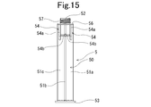
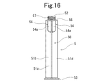
- the plunger 5 includes a plunger main body portion 50 and a front end portion 52 for mounting on the gasket 4 protruding from the plunger main body portion 50 in the front end direction.
- the plunger main body 50 includes a flange portion 56, a pressing portion 53, and a reinforcing portion 54.
- the plunger main body 50 includes a shaft portion formed in a cross shape in cross section, and the shaft portion is formed by four flat plate portions 51a, 51b, 51c, and 51d.
- the flange 56 is provided in the front-end
- the mounting tip 52 is a protrusion provided at the tip of the plunger 5.
- the mounting tip 52 protrudes forward (toward the tip) from near the center of the flange 56.
- the mounting tip 52 is preferably a cylindrical portion, but may be a rod-shaped portion. In this embodiment, as shown in FIG. 17, the mounting tip 52 is a cylindrical portion having a cross-shaped reinforcing portion inside.
- a plunger side screwing portion 57 that is screwed with the gasket side screwing portion 43 of the gasket 4 is provided on the outer surface of the mounting tip portion 52.
- the plunger side screwing portion 57 is formed by a spiral rib. Two (two) spiral ribs 57 are provided so as to correspond to the spiral threaded portion 43 of the gasket 4. Only one (one) spiral rib may be sufficient. And in the syringe of this Example, both the gasket 4 and the plunger 5 mentioned later will be in an attachment state by rotating the plunger 5.
- the plunger 5 of this embodiment includes four reinforcing portions 54 provided at the distal end portion of the main body portion 50.
- each reinforcing portion 54 includes a flat plate-shaped axial reinforcing portion 54 a and a circumferential reinforcing portion 54 b in which one end of the axial reinforcing portion 54 a and one end are joined.
- the axial reinforcing portion 54a is a flat plate extending a predetermined length so as to be orthogonal to the surface of any flat plate portion 51a, 51b, 51c, 51d constituting the shaft portion and also orthogonal to the rear end surface of the flange 56. It has become a shape.
- the axial direction reinforcement part 54a is provided so that it may become substantially parallel to the central axis of a plunger.
- the axial length of the axial reinforcing portion 54a is preferably about 1/6 to 1/4 of the total length of the shaft portion (the total length of the flat plate portion).
- the axial direction reinforcing part 54a has a chamfered shape or an arc shape at its end (base end).
- the circumferential reinforcing portion 54b is provided at a position slightly closer to the distal end side (flange 56 side) than the proximal end side end portion of the axial reinforcing portion.
- the circumferential reinforcing portion connects the shaft portions facing the axial reinforcing portion 54a, one end in the circumferential direction extends from one side surface of the axial reinforcing portion 54a, and the other end faces the axial reinforcing portion 54a.
- the bottom surface is connected to the flat plate portion from which the axial reinforcing portion 54a protrudes. That is, the circumferential reinforcing portion 54b connects the two flat plate portions with the axial reinforcing portion 54a adjacent to the circumferential reinforcing portion 54b.
- the circumferential reinforcing portion 54 b is provided so as to be substantially parallel to the flange 56.
- a hard or semi-hard resin such as high density polyethylene, polypropylene, polystyrene, polyethylene terephthalate.
- the chemical solution 8 filled in the space formed by the outer cylinder 2, the gasket 4, and the sealing member include, for example, a contrast medium, high-concentration sodium chloride injection, minerals, heparin sodium aqueous solution, nitroglycerin, isosorbide nitrate, Cyclosporine, benzodiazepines, antibiotics, vitamins (general vitamins), various amino acids, antithrombotics such as heparin, insulin, antitumor agents, analgesics, cardiotonic agents, intravenous anesthetics, antiparkinson agents, ulcer treatment Agents, corticosteroids, arrhythmic agents, correction electrolytes, antiviral agents, immunostimulants, and the like.
- the prefilled syringe 1 (outer cylinder 2) is attached to an automatic administration device such as an injector or syringe pump having a flange housing portion into which the flange 23 of the outer cylinder 2 is inserted, and is administered. It is preferable.
- an automatic administration device such as an injector or syringe pump having a flange housing portion into which the flange 23 of the outer cylinder 2 is inserted, and is administered.
- the drug solution 8 administered in this way include a contrast agent for angiography.
- the syringe of the present invention is as follows. (1) A cylindrical main body having an opening formed at the base end, a nozzle provided at the distal end and having a diameter smaller than that of the main body, and a tapered shoulder connecting the main body and the nozzle. A syringe that is housed in the main body portion of the outer tube and is slidable in a liquid-tight state in the main body portion, the gasket at the distal end and the shoulder portion A front end surface substantially matching the inner surface shape of the first annular rib, a first annular rib formed on the outer peripheral portion and positioned on the distal end side, and a second annular rib positioned on the proximal end side from the first annular rib.
- the first annular rib has at least a maximum outer diameter portion, a reduced-diameter annular portion that is curved so that an outer diameter decreases from the maximum outer diameter portion toward the distal end surface, and Between the annular distal end of the reduced diameter annular portion and the annular proximal end of the distal end surface, a recess and There is no step, and it is smoothly continuous.
- the gasket is in a state before insertion of the outer cylinder into the main body, and the outer diameter of the maximum outer diameter is larger than the inner diameter of the main body.
- the outer diameter of the tip of the reduced diameter annular portion is a syringe smaller than the inner diameter of the main body portion.
- a reduced-diameter annular portion is formed from the maximum outer diameter portion of the gasket toward the distal end surface, and the outer diameter of the distal end of the reduced-diameter annular portion is smaller than the inner diameter of the cylindrical main body portion of the outer cylinder. Therefore, when the gasket is inserted into the cylindrical main body, at least a part of the reduced-diameter annular portion remains without being compressed. For this reason, the contact angle between the inner peripheral surface of the body portion and the annular rib at the tip becomes loose, and the sliding resistance becomes small.
- the gasket has a tip surface that substantially matches the inner surface shape of the shoulder portion of the outer cylinder, and between the tip surface of the gasket, the annular tip of the reduced diameter annular portion, and the annular base end of the tip surface.
- the tip surface of the gasket There are no recesses and steps, and it is smoothly continuous. For this reason, there is little dead space formed between a shoulder part and a gasket front-end
- the gasket includes an annular recess formed between the first annular rib and the second annular rib, and an outer diameter of a tip of the reduced diameter annular portion is smaller than an outer diameter of the annular recess.
- the syringe according to (1) which is an object.
- the gasket includes an annular recess formed between the first annular rib and the second annular rib, and the diameter of the midpoint between the distal end and the base end of the reduced-diameter annular portion is the annular shape.
- the syringe according to (1) which is smaller than the outer diameter of the recess.
- the diameter of the midpoint between the distal end and the base end of the reduced diameter annular portion is smaller than the inner diameter of the main body of the outer cylinder.
- the gasket includes a slidable coating provided on the annular rib.
- the outer diameter of the maximum outer diameter portion of the gasket is 1.02 to 1.07 times the inner diameter of the main body portion of the outer cylinder, according to any one of (1) to (7) above Syringe.
- the syringe includes a sealing member that seals the nozzle portion of the outer cylinder, and a prefilled syringe that includes a chemical solution filled in a space formed by the outer cylinder, the gasket, and the sealing member.
- the syringe according to any one of (1) to (9) above.
- (11) The syringe according to (10), wherein the chemical solution is a contrast agent.
Landscapes
- Health & Medical Sciences (AREA)
- Vascular Medicine (AREA)
- Engineering & Computer Science (AREA)
- Anesthesiology (AREA)
- Biomedical Technology (AREA)
- Heart & Thoracic Surgery (AREA)
- Hematology (AREA)
- Life Sciences & Earth Sciences (AREA)
- Animal Behavior & Ethology (AREA)
- General Health & Medical Sciences (AREA)
- Public Health (AREA)
- Veterinary Medicine (AREA)
- Infusion, Injection, And Reservoir Apparatuses (AREA)
Abstract
La présente invention concerne une seringue (1) qui comprend les éléments suivants : un tube extérieur (2) ayant un corps principal cylindrique (21), une partie buse (24), et un épaulement conique (27) raccordant le corps principal (21) et la partie buse (24) ; et un joint (4) replié à l'intérieur du corps principal (21) du tube extérieur (2). Le joint (4) a une surface d'extrémité distale conique (41) correspondant sensiblement à la forme d'une surface intérieure (27a) de l'épaulement (27), une première nervure annulaire (44) positionnée sur un côté d'extrémité distale, et une seconde nervure annulaire (45) positionnée sur un côté d'extrémité proximale. La première nervure annulaire (44) a une partie à diamètre extérieur maximal et une partie annulaire à diamètre réduit (48) qui est incurvée de manière à ce que le diamètre extérieur rétrécisse progressivement, de la partie à diamètre extérieur maximal en direction de la surface d'extrémité distale, après quoi se trouve un raccord, sans renfoncement ni palier, entre une extrémité distale annulaire (48a) de la partie annulaire à diamètre réduit (48) et une extrémité proximale annulaire de la surface d'extrémité distale (41). L'état du joint (4) avant l'insertion dans le tube extérieur (2) est tel que le diamètre extérieur (D1) de la partie à diamètre extérieur maximal de la première nervure annulaire (44) est supérieur au diamètre intérieur (D2) du corps principal (21), et un diamètre extérieur (D3) de l'extrémité distale (48a) de la partie annulaire à diamètre réduit (48) est inférieur au diamètre interne (D2) du corps principal (21).
Priority Applications (1)
| Application Number | Priority Date | Filing Date | Title |
|---|---|---|---|
| PCT/JP2013/059267 WO2014155607A1 (fr) | 2013-03-28 | 2013-03-28 | Seringue |
Applications Claiming Priority (1)
| Application Number | Priority Date | Filing Date | Title |
|---|---|---|---|
| PCT/JP2013/059267 WO2014155607A1 (fr) | 2013-03-28 | 2013-03-28 | Seringue |
Publications (1)
| Publication Number | Publication Date |
|---|---|
| WO2014155607A1 true WO2014155607A1 (fr) | 2014-10-02 |
Family
ID=51622681
Family Applications (1)
| Application Number | Title | Priority Date | Filing Date |
|---|---|---|---|
| PCT/JP2013/059267 Ceased WO2014155607A1 (fr) | 2013-03-28 | 2013-03-28 | Seringue |
Country Status (1)
| Country | Link |
|---|---|
| WO (1) | WO2014155607A1 (fr) |
Citations (2)
| Publication number | Priority date | Publication date | Assignee | Title |
|---|---|---|---|---|
| JP3134991U (ja) * | 2007-06-19 | 2007-08-30 | 株式会社トップ | プレフィルドシリンジ用ガスケット |
| US20070219508A1 (en) * | 2006-03-15 | 2007-09-20 | Medrad, Inc. | Plunger Covers and Plungers for Use in Syringes and Methods of Fabricating Plunger Covers and Plungers for Use in Syringes |
-
2013
- 2013-03-28 WO PCT/JP2013/059267 patent/WO2014155607A1/fr not_active Ceased
Patent Citations (2)
| Publication number | Priority date | Publication date | Assignee | Title |
|---|---|---|---|---|
| US20070219508A1 (en) * | 2006-03-15 | 2007-09-20 | Medrad, Inc. | Plunger Covers and Plungers for Use in Syringes and Methods of Fabricating Plunger Covers and Plungers for Use in Syringes |
| JP3134991U (ja) * | 2007-06-19 | 2007-08-30 | 株式会社トップ | プレフィルドシリンジ用ガスケット |
Similar Documents
| Publication | Publication Date | Title |
|---|---|---|
| JP5767208B2 (ja) | プレフィルドシリンジ | |
| CN102639174B (zh) | 预充式注射器 | |
| JP5048472B2 (ja) | 注射器およびプレフィルドシリンジ | |
| WO2001097885A1 (fr) | Seringue | |
| JP6395707B2 (ja) | 注射器およびプレフィルドシリンジ | |
| JP5896669B2 (ja) | シリンジ用プランジャー、シリンジおよびプレフィルドシリンジ | |
| JP5714268B2 (ja) | プレフィルドシリンジ | |
| JP5489548B2 (ja) | プレフィルドシリンジ | |
| JP2010246842A (ja) | シリンジ | |
| JP5784438B2 (ja) | プレフィルドシリンジ | |
| JP4563021B2 (ja) | シリンジ | |
| JP5450731B2 (ja) | シリンジ | |
| JP5824200B2 (ja) | プレフィルドシリンジ | |
| JP5824223B2 (ja) | 2連式プレフィルドシリンジ | |
| JP5634695B2 (ja) | 注射器およびプレフィルドシリンジ | |
| WO2014155607A1 (fr) | Seringue | |
| JP5411556B2 (ja) | プレフィルドシリンジ用注射器およびプレフィルドシリンジ | |
| JP4299509B2 (ja) | プレフィルドシリンジ用注射器およびプレフィルドシリンジ | |
| JP2003245350A (ja) | シリンジ用ガスケット及びそれを用いたシリンジ | |
| JPWO2017047295A1 (ja) | シリンジ用プランジャおよびそれを用いたプレフィルドシリンジ | |
| JP4355151B2 (ja) | プレフィルドシリンジ用注射器およびプレフィルドシリンジ | |
| JP5394183B2 (ja) | プレフィルドシリンジ | |
| US20230149631A1 (en) | Pre-filled syringe | |
| JP3191047U (ja) | プレフィルドシリンジ用注射器およびプレフィルドシリンジ | |
| JP2024115477A (ja) | シリンジ用外筒組立体、シリンジおよびプレフィルドシリンジ |
Legal Events
| Date | Code | Title | Description |
|---|---|---|---|
| 121 | Ep: the epo has been informed by wipo that ep was designated in this application |
Ref document number: 13879864 Country of ref document: EP Kind code of ref document: A1 |
|
| NENP | Non-entry into the national phase |
Ref country code: DE |
|
| 122 | Ep: pct application non-entry in european phase |
Ref document number: 13879864 Country of ref document: EP Kind code of ref document: A1 |
|
| NENP | Non-entry into the national phase |
Ref country code: JP |