WO2014155669A1 - Dispositif de commande d'alimentation d'élément d'alimentation et procédé pour celui-ci - Google Patents
Dispositif de commande d'alimentation d'élément d'alimentation et procédé pour celui-ci Download PDFInfo
- Publication number
- WO2014155669A1 WO2014155669A1 PCT/JP2013/059533 JP2013059533W WO2014155669A1 WO 2014155669 A1 WO2014155669 A1 WO 2014155669A1 JP 2013059533 W JP2013059533 W JP 2013059533W WO 2014155669 A1 WO2014155669 A1 WO 2014155669A1
- Authority
- WO
- WIPO (PCT)
- Prior art keywords
- feeder
- current production
- power
- mode
- component
- Prior art date
- Legal status (The legal status is an assumption and is not a legal conclusion. Google has not performed a legal analysis and makes no representation as to the accuracy of the status listed.)
- Ceased
Links
Images


Classifications
-
- H—ELECTRICITY
- H05—ELECTRIC TECHNIQUES NOT OTHERWISE PROVIDED FOR
- H05K—PRINTED CIRCUITS; CASINGS OR CONSTRUCTIONAL DETAILS OF ELECTRIC APPARATUS; MANUFACTURE OF ASSEMBLAGES OF ELECTRICAL COMPONENTS
- H05K13/00—Apparatus or processes specially adapted for manufacturing or adjusting assemblages of electric components
- H05K13/08—Monitoring manufacture of assemblages
- H05K13/0885—Power supply
-
- H—ELECTRICITY
- H05—ELECTRIC TECHNIQUES NOT OTHERWISE PROVIDED FOR
- H05K—PRINTED CIRCUITS; CASINGS OR CONSTRUCTIONAL DETAILS OF ELECTRIC APPARATUS; MANUFACTURE OF ASSEMBLAGES OF ELECTRICAL COMPONENTS
- H05K13/00—Apparatus or processes specially adapted for manufacturing or adjusting assemblages of electric components
- H05K13/04—Mounting of components, e.g. of leadless components
- H05K13/0417—Feeding with belts or tapes
- H05K13/0419—Feeding with belts or tapes tape feeders
Definitions
- the present invention relates to a feeder power supply control apparatus and method.
- Patent Document 1 proposes an apparatus that puts the motor of the tape feeder into a power saving mode when the period during which the operation of supplying parts from the tape feeder is not scheduled is a predetermined period or longer. .
- Patent Document 1 has a problem in that it is lacking in simplicity because it is necessary to obtain a period during which no operation of supplying parts from the tape feeder is scheduled.
- the present invention has been made to solve such a problem, and a main object thereof is to easily realize reduction of power consumption of the feeder.
- the feeder power control device of the present invention is A device for controlling the power supply of an electric feeder that sequentially supplies components to a component mounting machine, Determining means for determining whether the feeder is a feeder to be used in current production; For a feeder that is not likely to be used in the current production, control means for reducing the power supply compared to the feeder used in the current production, It is equipped with.
- This feeder power control device reduces power supply for feeders that are not likely to be used in current production compared to feeders used in current production. Therefore, when reducing the supply power, there is no need to obtain a period during which no operation for supplying parts from the feeder is planned as in the prior art. Therefore, it is possible to easily reduce the power consumption of the feeder.
- the control means sets the feeder used in the current production to a non-power-saving mode that allows parts to be supplied in accordance with a parts supply command, and uses the feeder in the current production.
- a feeder that is not likely to be used, it may be set in a power saving mode in which supply power is lower than that in the non-power saving mode. If it carries out like this, the feeder used by the present production will be in the state which can supply the component to a component mounting machine promptly according to a component supply command.
- the feeder used in the current production when the feeder that supplies the same component as the feeder used in the current production is present in the feeder, the feeder used in the current production is mounted on the component. Possibility to use in the current production, set as a master feeder that supplies parts to the machine immediately, and use a feeder that supplies the same parts as the master feeder as a spare when the master feeder runs out of parts
- the spare feeder is set to the power saving mode, the spare feeder is changed to the non-power saving mode immediately before the master feeder runs out of parts, and then the master feeder is set.
- the master feeder may be changed to the power saving mode. In this way, when the master feeder runs out of parts, it is possible to smoothly switch to the spare feeder, and power consumption of the used master feeder can be suppressed.
- the power saving mode may be a mode in which all power to the feeder is turned off. In this way, the power consumption of feeders that are not used in the current production can be eliminated, so that the power saving effect is high.
- the feeder power control method of the present invention is A method of controlling the power supply of an electric feeder that sequentially supplies components to a component mounting machine, Determining whether the feeder is a feeder to be used in current production; For a feeder that is not likely to be used in the current production, the step of reducing the power supply compared to the feeder used in the current production; Is included.
- This feeder power control method reduces power supply for feeders that are not likely to be used in current production compared to feeders used in current production. Therefore, when reducing the supply power, there is no need to obtain a period during which no operation for supplying parts from the feeder is planned as in the prior art. Therefore, it is possible to easily reduce the power consumption of the feeder.
- FIG. 1 is a schematic explanatory diagram of a component mounting system 1.
- FIG. FIG. 3 is an explanatory diagram of a reel unit 70.
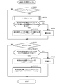
- 12 is a flowchart illustrating an example of a component shortage countermeasure processing routine according to a third embodiment.
- FIG. 1 is a schematic explanatory diagram of the component mounting system 1
- FIG. 2 is a perspective view of the component mounting machine 11, and FIG.
- the left-right direction (X-axis), the front-rear direction (Y-axis), and the up-down direction (Z-axis) are as shown in FIGS.
- the component mounting system 1 includes a plurality of component mounters 11 that form a mounting line, a reel unit 70 that supplies components to the component mounter 11, and a management computer 80 that manages the production of the board.
- the component mounter 11 includes a substrate transport device 18 that transports the substrate 16, a head 24 that can move on the XY plane, a suction nozzle 40 that is attached to the head 24 and can move to the Z axis, And a mounting machine controller 50 that executes various controls.
- the substrate transport device 18 transports the substrate 16 from left to right by conveyor belts 22 and 22 (only one is shown in FIG. 2) attached to the pair of left and right support plates 20 and 20, respectively.
- the head 24 moves in the left-right direction as the X-axis slider 26 moves in the left-right direction along the guide rails 28, 28, and the Y-axis slider 30 moves in the front-rear direction along the guide rails 32, 32.
- the suction nozzle 40 uses pressure to suck a component at the tip of the nozzle or to release a component sucked at the tip of the nozzle.
- the height of the suction nozzle 40 is adjusted by a Z-axis motor 34 built in the head 24 and a ball screw 36 extending along the Z-axis.
- the mounting machine controller 50 is configured as a microprocessor centered on a CPU, and is connected to the substrate transport device 18, the X-axis slider 26, the Y-axis slider 30, and the head 24 so as to exchange signals.
- the reel unit 70 is mounted in front of the component mounter 11 as shown in FIG.
- the reel unit 70 has a plurality of slots 71, and a feeder 72 can be inserted into each slot 71.
- the feeder 72 has a feeder connector 77 on the rear side.
- the feeder connector 77 and the slot connector 78 are electrically connected.
- a reel 73 around which a tape T is wound is attached to the feeder 72.
- components are held in a state of being aligned along the longitudinal direction of the tape. These parts are protected by a film covering the surface of the tape T.
- Such a tape T is fed out as the sprocket 74 is rotated by the motor 75 with the teeth of the sprocket 74 meshing with holes formed along the longitudinal direction of the tape T, and the film is peeled off to remove the parts.
- the predetermined position is a position where the suction nozzle 40 can suck the component. Since the suction nozzle 40 that sucks the component at the predetermined position can move in the XYZ directions, the component can be mounted at a predetermined position on the substrate 16.
- the motor 75 is controlled by a feeder controller 76 built in the feeder 72.
- a feeder controller 76 built in each feeder 72 is connected to the mounting machine controller 50 via a feeder connector 77 and a slot connector 78 so as to be capable of bidirectional communication.
- the power supply to the feeder 72 is performed by the mounting machine controller 50 through the feeder connector 77 and the slot connector 78 using two systems of a power line to the feeder controller 76 and a power line to the motor 75.
- the management computer 80 includes a personal computer main body 82, an input device 84, and a display 86, can input signals from the input device 84 operated by an operator, and can output various images to the display 86.
- production job data of the substrate 16 is stored.
- each component mounting machine 11 which component is mounted on which substrate type 16 in which order from which slot position feeder, and how many substrates 16 are mounted in that order. Etc. are defined.
- Tables 1 and 2 show examples of production job data for current production and next production, respectively.
- the supply of the part type A is first received from the feeder 72 inserted into the slot position # 1 of the reel unit 70, and then the part type B is supplied from the feeder 72 inserted into the slot position # 5.
- the components are mounted on 100 substrates 16 of the substrate type ⁇ in the order of receiving the components and then receiving the components C from the feeder 72 inserted into the slot position # 9.
- the production job for the next production is a job for sequentially mounting the components on the board 16 of the board type ⁇ . After the production job for the current production is completed, the job is moved up to the production job for the current production.
- the management computer 80 is connected to the mounter controller 50 of each component mounter 11 so that bidirectional communication is possible.
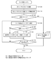
- FIG. 4 is a flowchart showing an example of a mode setting routine executed by the mounting machine controller 50.
- a necessary feeder 72 is inserted into the reel unit 70 at a slot position corresponding to the current production.
- the production job data of the current production is shown in Table 1.
- the feeder controller 76 of each feeder 72 stores the feeder number, the part type, and the number of parts held (the number of parts held on the tape T wound around the reel 73) in the internal memory as feeder information.
- An example of the feeder information is shown in Table 3.
- the operator sets each feeder 72 in the slot 71 based on the production job.
- feeder 72 with feeder number 01 at slot position # 1 feeder 72 with feeder number 02 at slot position # 5, and feeder 72 with feeder number 03 at slot position # 9.
- feeder 72 with feeder number 04 is used in the next production as shown in Table 2, and is therefore set at slot position # 2 in accordance with production job data for the next production.
- the feeder 72 with feeder number 05 is set at an arbitrary position. Here, it is assumed that feeder 72 with feeder number 05 is set at slot position # 6.
- the operator sets the feeder 72 in the slot 71 based on the production job data and feeder information of the current production, and then turns on a mode setting start button (not shown) of the component mounter 11. Then, the mounting machine controller 50 reads the mode setting routine from the internal memory and executes it. When the mounting machine controller 50 receives new production job data from the management computer 80, the mounting machine controller 50 resets the previously set mode and waits for the mode setting start button to be turned on again.
- the mounting machine controller 50 supplies power to the feeder controller 76 incorporated in each feeder 72 to perform bidirectional communication (step S100), and the slot position of each feeder 72 and the feeder. Information is acquired and the relationship is stored in the internal memory (step S110). An example of the relationship between the slot position and the feeder information is shown in Table 4. Note that the feeder 72 is not inserted into the slot position not shown in Table 4.
- the mounter controller 50 determines whether or not the power saving mode is set in the component mounter 11 (step S120).
- the power saving mode is set when the operator selects a power saving button (not shown) in the component mounter 11.
- the standby mode is a mode in which the feeder 72 waits so as to supply components in response to a component supply command from the mounting machine controller 50, and is an example of the non-power saving mode of the present invention. In this standby mode, the component mounter 11 supplies power to the feeder controller 76 but does not supply power to the motor 75.
- step S120 the mounting machine controller 50 selects one feeder 72 for which the mode is not set.
- the feeder numbers are selected in descending order.
- step S140 it is determined whether or not the selected feeder 72 is a feeder used in the current production. This determination is made based on whether or not the slot position of the selected feeder 72 and the component type are associated with each other and registered in the production job data of the current production. If the feeder 72 selected in step S140 is a feeder used in the current production, the feeder 72 is set to the standby mode (step S150). If the feeder 72 is not likely to be used in the current production, the feeder 72 is selected. 72 is set to the unused mode (step S160).
- the selected feeder 72 is the feeder 72 with the feeder number 01
- the slot position # 01 and the part type A are associated with each other and registered in the production job data of the current production.
- the selected feeder 72 is the feeder 72 with the feeder number 04
- the slot position # 02 and the part type D are associated with each other and are not registered in the production job data of the current production. It is determined that the feeder has no possibility, and the unused mode is set. In the unused mode, the component mounter 11 does not supply power to the feeder controller 76 or the motor 75. That is, all the power sources of the feeder 72 are turned off. For this reason, less power is supplied to the feeder 72 in the unused mode than the feeder 72 in the standby mode.
- This unused mode is an example of the power saving mode of the present invention.
- step S150 or step S160 the mounting machine controller 50 determines whether or not the mode has been set for all the feeders 72 mounted on the reel unit 70 (step S170). If the feeder 72 whose mode is not set remains in step S170, the processing after step S130 is executed again, and if the mode has been set for all the feeders 72 attached to the reel unit 70 in step S170, This routine ends.
- the feeders 72 with feeder numbers 01, 02, and 03 inserted into the slot positions # 1, # 5, and # 9 are set to the standby mode, and the slot positions # 2, # 6 are set.
- the feeders 72 having feeder numbers 04 and 05 inserted therein are set to the unused mode.
- FIG. 5 is a flowchart showing an example of a component supply processing routine. Since the feeder controller 76 continues to receive power from the component mounting machine 11 after being set to the standby mode, this routine can be executed. Note that the feeder controller 76 set to the unused mode does not execute this routine because power is not supplied from the component mounter 11.
- the feeder controller 76 When the component supply processing routine is started, the feeder controller 76 first determines whether or not an operation preparation signal has been received from the mounting machine controller 50 (step S200). When the operation preparation signal is received, a request for changing to the operation mode is transmitted to the mounting machine controller 50 (step S210).
- the operation preparation signal is a signal for prompting preparation for component supply, and specifically, a signal for setting the feeder 72 to the operation mode.
- the mounting machine controller 50 supplies power to both the feeder controller 76 and the motor 75 to place the feeder 72 in the operation mode.
- the operation mode is a mode in which the feeder 72 can immediately supply components in response to a component supply command from the mounting machine controller 50, and is an example of the non-power saving mode of the present invention.
- the feeder controller 76 determines whether or not a component supply instruction signal has been received from the mounting machine controller 50 (step S220). If this signal has not been received, the feeder controller 76 waits as it is, and if this signal has been received. Component supply is executed (step S230). The parts are supplied by rotating the sprocket 74 and controlling the motor 75 so that the parts on the tape T are supplied to a predetermined position. After executing the component supply, it is determined whether or not the next operation preparation signal is received from the mounting machine controller 50 (step S240). If the next operation preparation signal is received, the process returns to step S220. Thereby, when the component mounter 11 continuously receives supply of components from the feeder 72, the operation mode of the feeder 72 is continued.
- step S240 if the next operation preparation signal is not received from the mounting machine controller 50 in step S240, a request for changing to the standby mode is transmitted to the mounting machine controller 50 (step S250), and the process returns to step S200 again. Then, the mounting machine controller 50 that has received this change request supplies power only to the feeder controller 76 and stops supplying power to the motor 75. As a result, when the component mounter 11 does not continuously receive component supply from the feeder 72, the feeder 72 is set to the standby mode, which contributes to power saving. This routine ends when the production job data is updated.
- the mounting machine controller 50 of the present embodiment corresponds to a feeder power supply control device of the present invention.
- an example of the feeder power control method of the present invention is also clarified by describing the operation of the mounting machine controller 50.
- the power supply of the feeder 72 that is not likely to be used in the current production is reduced compared to the feeder 72 that is used in the current production. Therefore, when reducing the power supply, it is not necessary to obtain a period during which no operation for supplying parts from the feeder 72 is planned as in the prior art. Therefore, the power consumption of the feeder 72 can be easily reduced.
- the feeder 72 used in the current production is in a state in which it is possible to quickly supply the components to the component mounting machine 11 according to the component supply command, and in the unused mode, the feeder 72 is used in the current production. Since the power consumption of the feeder 72 that has no possibility of being eliminated can be eliminated, the power saving effect is high.
- the component mounting system 1 of the second embodiment has the same configuration as that of the first embodiment. Therefore, description of the structure of the component mounting system 1 is abbreviate
- the data in Table 1 is used as production job data for the current production.
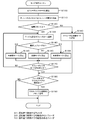
- a mode setting routine executed by the mounting machine controller 50 will be described with reference to the flowchart of FIG.
- This mode setting routine is the same as the mode setting routine of the first embodiment except that steps S110, S140, S165, S185, and S190 are different. Therefore, only the steps different from the first embodiment will be described below.
- step S140 it is determined whether the selected feeder corresponds to a feeder used in the current production, a feeder that is not likely to be used in the current production, or a feeder that may be used in the current production. .
- the selected feeder is not a feeder used in the current production, it is determined whether or not it is a feeder that holds the same part type as the part type used in the current production. It is determined that the feeder is a possibility, and if the determination is negative, it is determined that the feeder is not likely to be used in the current production.
- the feeder used in the current production is set to the standby mode (step S150), and the feeder that may be used in the current production or the feeder that is not likely to be used is set to the unused mode (steps S160 and S165). ).
- the feeder 72 with the feeder number 05 inserted into the slot position # 6 is not used immediately in the current production, but has the part type A used in the current production, and therefore may be used in the current production. It is determined that it is a feeder, and the unused mode is set.
- the mounting machine controller 50 determines whether or not there is a master feeder-spare feeder relationship between the feeders after the affirmative determination in step S170 or after step S180 (step S185). If there is such a relationship, the relationship is stored in the internal memory of the mounting machine controller 50 (step S190), and this routine is terminated. Specifically, in step S185, when there are a plurality of feeders holding the same part type as the part type used in the current production, the feeder registered in the production job data of the current production is selected as the master feeder and the current production. A feeder that is not registered in the production job data is recognized as a spare feeder, and in step S190, the relationship is registered in the internal memory. If there is no relationship between the master feeder and the spare feeder in step S185, this routine is finished as it is. The spare feeder has been determined as a feeder that may be used in the current production in step S140.
- the production job data of the current production is as shown in Table 1 as described above, and the number of boards to be produced is 100.
- the components are mounted on the substrate 16 of the substrate type ⁇ in the order of the component types A, B, and C, but are inserted into the slot position # 1.
- the feeder 72 having the feeder number 01 holds only 50 parts of the part type A, and becomes short on the way.
- the feeder 72 with feeder number 05 inserted into the slot position # 6 similarly holds 50 parts of part type A. For this reason, if the parts are supplied from the feeder 72 at the slot position # 6 after the feeder 72 at the slot position # 1 has run out of parts, 100 substrates can be produced.
- step S185 the feeder 72 at slot position # 1 and the feeder 72 at slot position # 6 hold parts of the same part type A, and the former is registered and the latter is registered in the production job data of the current production. Therefore, the former is registered as a master feeder and the latter is registered as a spare feeder (see the right side of Table 5).
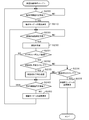
- the feeder controller 76 determines whether or not its own feeder 72 is registered as a master feeder after supplying the component in accordance with the component supply instruction in step S230 (step S231). This determination is made based on whether or not the feeder 72 is associated with the master feeder and the spare feeder registered in the internal memory in step S190 described above. If the feeder 72 has been registered as a master feeder, it is determined whether or not the current time is the part-out notice timing (step S232). This determination is made based on whether or not the remaining amount of parts supplied by the feeder 72 has reached a predetermined threshold (for example, 5 or 7). Note that the remaining amount of parts is calculated by subtracting the number of parts consumed from the number of parts held at the start of production.
- a predetermined threshold for example, 5 or 7
- step S233 the part-out notice timing
- step S235 the processing after step S240 described above is performed.
- step S235 it is determined whether the current time is the part-out time. This determination is made based on whether or not the remaining amount of parts has become zero. If it is the component out timing in step S234, a request for changing to the unused mode is transmitted to the mounting machine controller 50 (step S235), and this routine is terminated.
- the mounting machine controller 50 that has received the request for changing to the unused mode stops the power supply to the feeder controller 76 and the motor 75. Also, if the feeder 72 is not registered in the master feeder in step S231 or if it is not the part-out timing in step S234, the processing after step S240 described above is performed.
- the component shortage countermeasure processing routine is started at predetermined timings (for example, every several seconds).
- the mounter controller 50 determines whether or not a part cut notice has been received from any feeder controller 76 (step S300). Is changed from the unused mode to the standby mode (step S310). Since the feeder 72 that transmits a part-out notice in the middle is registered in the internal memory of the mounting machine controller 50 as a master feeder, a corresponding spare feeder is also registered. In step S310, the spare leader is changed from the unused mode to the standby mode.
- step S310 After step S310, or when no part-out notice has been received from anywhere in step S300, it is determined whether or not a part-out has been received from any feeder controller 76 (step S320). If a component cut is received, the feeder 72 that has transmitted the component cut is changed to an unused mode (step S330), and the feeder 72 registered as a spare feeder is rewritten to a master feeder (step S340). After this step S340, or when no part-out has been received from anywhere in step S320, this routine is terminated.
- the following effects can be obtained in addition to the effects of the first embodiment. That is, even when one feeder cannot cover all the parts of one part type used in the current production, the master feeder and the spare feeder are prepared, so that it is possible to cope with it.
- the spare feeder functions as the master feeder after the master feeder has run out of parts.
- the original master feeder is changed to the unused mode, power consumption can be suppressed.
- the spare feeder is switched from the unused mode to the standby mode at the timing of the part-out notice, it is possible to smoothly switch to the spare feeder when the original master feeder is out of parts.
- the component mounting system 1 according to the third embodiment has the same configuration as that of the first embodiment. Therefore, description of the structure of the component mounting system 1 is abbreviate
- the mode setting routine executed by the mounting machine controller 50 and the component supply processing routine executed by the feeder controller 76 are the same as those in the second embodiment, and thus the description thereof is omitted here.
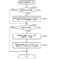
- the part cut countermeasure processing routine executed by the mounting machine controller 50 will be described with reference to the flowchart of FIG.
- This part cut countermeasure processing routine is the same as that of the second embodiment except that steps S301 to S304 are executed instead of step S310, and steps S321 and S322 are executed between steps S320 and S330. Therefore, only steps different from those of the second embodiment will be described below.
- the mounting machine controller 50 executes the mode setting routine (see FIG. 6) described in the second embodiment when receiving the notice of component shortage from any feeder controller 76 in step S300.
- This mode setting routine is executed after supplying power to all the feeder controllers 76.
- it is determined whether or not there is a feeder 72 in the unused mode corresponding to the spare feeder of the feeder 72 that has transmitted the part-out notice (step S302).
- the standby mode is set, and it is registered in the internal memory as a spare feeder of the feeder 72 that has transmitted the part-out notice (step S303).
- a negative determination is made in step S302
- a warning is output to the operator because it becomes impossible to deal with a component shortage (step S304).
- step S303 or S304 the mounting machine controller 50 proceeds to step S320, and if it receives out of parts from any of the feeder controllers 76, is the spare feeder of the feeder 72 that has transmitted the notice of out of parts registered? It is determined whether or not (step S321). If an affirmative determination is made in step S321, the processing after step S330 described above is executed. On the other hand, if a negative determination is made in step S321, the mounting operation is stopped because it is not possible to deal with a component shortage (step S322), and this routine is terminated.
- feeders that were in the relationship between the master feeder and the spare feeder at the beginning of the current production may be removed from the slot 71 or inserted into another slot 71 during the current production. is there. Even in such a case, since the feeder 72 is checked again at the timing of receiving the part-out notice and the mode is assigned, a spare feeder can be found, and even if the part is out, it can be handled smoothly.
- a feeder detector for detecting insertion / removal of the feeder 72 to / from the slot 71 may be provided.
- the following processing may be performed in place of steps S301 to S304 of the component shortage countermeasure processing routine of FIG. That is, based on the signal from the feeder detector, it is determined whether or not the spare feeder of the feeder that has transmitted the part-out notice has been inserted into the slot as it is.
- the setting may be changed from the use mode to the standby mode, and a warning may be output if the original mode is not maintained.
- Table 6 may be adopted as production job data.
- the supply of the part type A is received from the feeder 72 inserted into the slot position # 1, and then the supply of the part type B is received from the feeder 72 inserted into the slot position # 5.
- the components 72 of the component type C are supplied from the feeder 72 inserted into the slot position # 9, and are mounted on the 100 substrates 16 of the substrate type ⁇ .
- the feeder 72 inserted into the slot position # 1 and the feeder 72 inserted into the slot position # 04 have a master-spare relationship, and the former is the master feeder and the latter is the spare feeder. .
- steps S185 and S190 of the mode setting routine (FIG.
- step S140 of the mode setting routine in FIG. It is determined that the existing feeder is not a feeder used in the current production but a feeder that may be used in the current production. For example, since the feeder 72 with the feeder number 05 is a spare feeder, it is determined in step S140 that the feeder 72 may be used for the current production, and the unused mode is set.
- the power supply control of the feeder 72 is performed by the mounting machine controller 50, but may be performed by the management computer 80 or the feeder controller 76.
- the management computer 80 corresponds to the control means of the present invention
- the feeder controller 76 corresponds to the control means of the present invention.
- the power supply control of the feeder 72 may be shared by a plurality of controllers or the like. In that case, a plurality of controllers and the like correspond to the control means of the present invention.
- the relationship between the slot position acquired in step S110, the feeder number, and the component type (Table 4) is the relationship between the slot position of the production job, the feeder number, and the component type (Table 1). It is also possible to check whether or not it matches, and output a warning if it does not match.
- the component mounting system 1 has been described as including a plurality of (four) component mounters 11.
- the component mount system 1 may include a single component mounter 11.
- the mode setting routine is started when the mode setting start button is turned on.
- the mode setting routine may be automatically started by using a production job switching or feeder setting as a trigger.
- a feeder setting is used as a trigger, the mode setting routine only needs to be performed for the set feeder.
- a feeder that may be used in the current production is set to the unused mode (steps S140 and S160). May be set.
- the feeder used in the current production is set to the standby mode in the mode setting routine (steps S140 and S150), but may be set to the operation mode.
- the feeder can take two modes, an unused mode and an operation mode.
- the present invention can be used for a component mounter for mounting components on a substrate.
Landscapes
- Engineering & Computer Science (AREA)
- Manufacturing & Machinery (AREA)
- Microelectronics & Electronic Packaging (AREA)
- Operations Research (AREA)
- Supply And Installment Of Electrical Components (AREA)
Abstract
Priority Applications (4)
| Application Number | Priority Date | Filing Date | Title |
|---|---|---|---|
| CN201380075250.5A CN105075418B (zh) | 2013-03-29 | 2013-03-29 | 供料器电源控制装置及其方法 |
| JP2015507870A JP6067840B2 (ja) | 2013-03-29 | 2013-03-29 | フィーダ電源制御装置及びその方法 |
| PCT/JP2013/059533 WO2014155669A1 (fr) | 2013-03-29 | 2013-03-29 | Dispositif de commande d'alimentation d'élément d'alimentation et procédé pour celui-ci |
| EP13880447.1A EP2981161B1 (fr) | 2013-03-29 | 2013-03-29 | Dispositif de commande d'alimentation d'élément d'alimentation et procédé pour celui-ci |
Applications Claiming Priority (1)
| Application Number | Priority Date | Filing Date | Title |
|---|---|---|---|
| PCT/JP2013/059533 WO2014155669A1 (fr) | 2013-03-29 | 2013-03-29 | Dispositif de commande d'alimentation d'élément d'alimentation et procédé pour celui-ci |
Publications (1)
| Publication Number | Publication Date |
|---|---|
| WO2014155669A1 true WO2014155669A1 (fr) | 2014-10-02 |
Family
ID=51622731
Family Applications (1)
| Application Number | Title | Priority Date | Filing Date |
|---|---|---|---|
| PCT/JP2013/059533 Ceased WO2014155669A1 (fr) | 2013-03-29 | 2013-03-29 | Dispositif de commande d'alimentation d'élément d'alimentation et procédé pour celui-ci |
Country Status (4)
| Country | Link |
|---|---|
| EP (1) | EP2981161B1 (fr) |
| JP (1) | JP6067840B2 (fr) |
| CN (1) | CN105075418B (fr) |
| WO (1) | WO2014155669A1 (fr) |
Cited By (4)
| Publication number | Priority date | Publication date | Assignee | Title |
|---|---|---|---|---|
| WO2018003102A1 (fr) * | 2016-06-30 | 2018-01-04 | 富士機械製造株式会社 | Système d'optimisation de programme de production et système de gestion de production |
| EP3383156A4 (fr) * | 2015-11-27 | 2018-12-12 | Fuji Corporation | Dispositif de commande d'alimentation électrique et procédé de commande d'alimentation électrique pour distributeur de composants |
| WO2024261807A1 (fr) * | 2023-06-19 | 2024-12-26 | 株式会社Fuji | Appareil de gestion d'opération et procédé de gestion d'opération pour dispositif d'alimentation |
| WO2025154210A1 (fr) * | 2024-01-17 | 2025-07-24 | 株式会社Fuji | Système d'alimentation en composants, dispositif de stockage et dispositif d'alimentation en composants |
Families Citing this family (4)
| Publication number | Priority date | Publication date | Assignee | Title |
|---|---|---|---|---|
| JP6815116B2 (ja) * | 2016-07-19 | 2021-01-20 | Juki株式会社 | 電子部品供給装置及び電子部品実装装置 |
| JP7163393B2 (ja) * | 2018-08-23 | 2022-10-31 | 株式会社Fuji | 移動作業管理装置、実装システム、移動型作業装置及び移動作業管理方法 |
| JP7059404B2 (ja) * | 2019-01-25 | 2022-04-25 | 株式会社Fuji | フィーダ決定方法、およびフィーダ決定装置 |
| KR102482140B1 (ko) | 2020-09-28 | 2022-12-27 | 한화정밀기계 주식회사 | 부품 실장기의 전원 제어장치 |
Citations (3)
| Publication number | Priority date | Publication date | Assignee | Title |
|---|---|---|---|---|
| JP2000307297A (ja) * | 1999-04-21 | 2000-11-02 | Matsushita Electric Ind Co Ltd | 電子部品実装機、及び該電子部品実装機にて実行される電力供給制御方法 |
| JP2003264399A (ja) * | 2002-03-11 | 2003-09-19 | Matsushita Electric Ind Co Ltd | 電子部品実装機、及び電力供給制御方法 |
| JP2008098355A (ja) | 2006-10-11 | 2008-04-24 | Juki Corp | 部品供給装置 |
Family Cites Families (3)
| Publication number | Priority date | Publication date | Assignee | Title |
|---|---|---|---|---|
| JP4386752B2 (ja) * | 2004-02-18 | 2009-12-16 | 富士機械製造株式会社 | 部品実装システムに対する部品供給方法及び部品供給装置 |
| CN100506006C (zh) * | 2004-07-16 | 2009-06-24 | 雅马哈发动机株式会社 | 表面安装机 |
| JP2007019281A (ja) * | 2005-07-08 | 2007-01-25 | Yamagata Casio Co Ltd | 部品搭載装置及びその部品搭載方法 |
-
2013
- 2013-03-29 EP EP13880447.1A patent/EP2981161B1/fr active Active
- 2013-03-29 WO PCT/JP2013/059533 patent/WO2014155669A1/fr not_active Ceased
- 2013-03-29 CN CN201380075250.5A patent/CN105075418B/zh active Active
- 2013-03-29 JP JP2015507870A patent/JP6067840B2/ja active Active
Patent Citations (3)
| Publication number | Priority date | Publication date | Assignee | Title |
|---|---|---|---|---|
| JP2000307297A (ja) * | 1999-04-21 | 2000-11-02 | Matsushita Electric Ind Co Ltd | 電子部品実装機、及び該電子部品実装機にて実行される電力供給制御方法 |
| JP2003264399A (ja) * | 2002-03-11 | 2003-09-19 | Matsushita Electric Ind Co Ltd | 電子部品実装機、及び電力供給制御方法 |
| JP2008098355A (ja) | 2006-10-11 | 2008-04-24 | Juki Corp | 部品供給装置 |
Cited By (5)
| Publication number | Priority date | Publication date | Assignee | Title |
|---|---|---|---|---|
| EP3383156A4 (fr) * | 2015-11-27 | 2018-12-12 | Fuji Corporation | Dispositif de commande d'alimentation électrique et procédé de commande d'alimentation électrique pour distributeur de composants |
| WO2018003102A1 (fr) * | 2016-06-30 | 2018-01-04 | 富士機械製造株式会社 | Système d'optimisation de programme de production et système de gestion de production |
| JPWO2018003102A1 (ja) * | 2016-06-30 | 2019-04-18 | 株式会社Fuji | 生産プログラム最適化システム及び生産管理システム |
| WO2024261807A1 (fr) * | 2023-06-19 | 2024-12-26 | 株式会社Fuji | Appareil de gestion d'opération et procédé de gestion d'opération pour dispositif d'alimentation |
| WO2025154210A1 (fr) * | 2024-01-17 | 2025-07-24 | 株式会社Fuji | Système d'alimentation en composants, dispositif de stockage et dispositif d'alimentation en composants |
Also Published As
| Publication number | Publication date |
|---|---|
| EP2981161A4 (fr) | 2016-07-27 |
| JPWO2014155669A1 (ja) | 2017-02-16 |
| CN105075418A (zh) | 2015-11-18 |
| CN105075418B (zh) | 2018-09-14 |
| JP6067840B2 (ja) | 2017-01-25 |
| EP2981161A1 (fr) | 2016-02-03 |
| EP2981161B1 (fr) | 2018-12-12 |
Similar Documents
| Publication | Publication Date | Title |
|---|---|---|
| JP6067840B2 (ja) | フィーダ電源制御装置及びその方法 | |
| EP3267782B1 (fr) | Dispositif de gestion de montage | |
| WO2020039495A1 (fr) | Système de montage de composants | |
| JP6896148B2 (ja) | 生産ジョブ処理方法 | |
| US20210315138A1 (en) | Moving work management device, moving work device, mounting system, and moving work management method | |
| JPWO2016170637A1 (ja) | 部品実装機、部品実装機の制御方法、部品実装機の制御プログラム、記録媒体、部品実装システム | |
| CN103857270B (zh) | 电子元件的安装方法以及表面安装机 | |
| JP6053572B2 (ja) | 実装装置及び実装方法 | |
| CN104170542B (zh) | 元件安装机 | |
| JP6194365B2 (ja) | 実装装置及び実装管理装置 | |
| JPWO2018198333A1 (ja) | 作業システム | |
| WO2020065809A1 (fr) | Système de montage de pièces | |
| EP3128825B1 (fr) | Dispositif de montage de composants électroniques | |
| JPWO2018134934A1 (ja) | 部品実装システム及びフィーダ作業用アタッチメント | |
| JP4777209B2 (ja) | 部品供給装置 | |
| JP6076790B2 (ja) | 電子部品実装装置 | |
| US20220110233A1 (en) | Management device, mounting device, mounting system, and management method | |
| JP6752086B2 (ja) | 実装管理装置 | |
| CN110313124B (zh) | 马达控制装置及供料器 | |
| WO2016181439A1 (fr) | Dispositif de montage et procédé de montage | |
| JP5805875B2 (ja) | コンベア式の部品供給装置及び表面実装機 | |
| JP3821526B2 (ja) | 部品実装装置 | |
| US20240130098A1 (en) | Feeder insertion/removal device and component mounting system | |
| JP2023184014A (ja) | 部品実装機 | |
| JP6866250B2 (ja) | 決定装置、決定方法、表面実装機 |
Legal Events
| Date | Code | Title | Description |
|---|---|---|---|
| WWE | Wipo information: entry into national phase |
Ref document number: 201380075250.5 Country of ref document: CN |
|
| 121 | Ep: the epo has been informed by wipo that ep was designated in this application |
Ref document number: 13880447 Country of ref document: EP Kind code of ref document: A1 |
|
| ENP | Entry into the national phase |
Ref document number: 2015507870 Country of ref document: JP Kind code of ref document: A |
|
| WWE | Wipo information: entry into national phase |
Ref document number: 2013880447 Country of ref document: EP |
|
| NENP | Non-entry into the national phase |
Ref country code: DE |