WO2014155997A1 - Capteur de vitesse angulaire - Google Patents
Capteur de vitesse angulaire Download PDFInfo
- Publication number
- WO2014155997A1 WO2014155997A1 PCT/JP2014/001298 JP2014001298W WO2014155997A1 WO 2014155997 A1 WO2014155997 A1 WO 2014155997A1 JP 2014001298 W JP2014001298 W JP 2014001298W WO 2014155997 A1 WO2014155997 A1 WO 2014155997A1
- Authority
- WO
- WIPO (PCT)
- Prior art keywords
- vibration
- unit
- angular velocity
- velocity sensor
- sensor according
- Prior art date
- Legal status (The legal status is an assumption and is not a legal conclusion. Google has not performed a legal analysis and makes no representation as to the accuracy of the status listed.)
- Ceased
Links
Images




Classifications
-
- G—PHYSICS
- G01—MEASURING; TESTING
- G01C—MEASURING DISTANCES, LEVELS OR BEARINGS; SURVEYING; NAVIGATION; GYROSCOPIC INSTRUMENTS; PHOTOGRAMMETRY OR VIDEOGRAMMETRY
- G01C19/00—Gyroscopes; Turn-sensitive devices using vibrating masses; Turn-sensitive devices without moving masses; Measuring angular rate using gyroscopic effects
- G01C19/56—Turn-sensitive devices using vibrating masses, e.g. vibratory angular rate sensors based on Coriolis forces
-
- G—PHYSICS
- G01—MEASURING; TESTING
- G01C—MEASURING DISTANCES, LEVELS OR BEARINGS; SURVEYING; NAVIGATION; GYROSCOPIC INSTRUMENTS; PHOTOGRAMMETRY OR VIDEOGRAMMETRY
- G01C19/00—Gyroscopes; Turn-sensitive devices using vibrating masses; Turn-sensitive devices without moving masses; Measuring angular rate using gyroscopic effects
- G01C19/56—Turn-sensitive devices using vibrating masses, e.g. vibratory angular rate sensors based on Coriolis forces
- G01C19/5642—Turn-sensitive devices using vibrating masses, e.g. vibratory angular rate sensors based on Coriolis forces using vibrating bars or beams
- G01C19/5649—Signal processing
-
- G—PHYSICS
- G01—MEASURING; TESTING
- G01C—MEASURING DISTANCES, LEVELS OR BEARINGS; SURVEYING; NAVIGATION; GYROSCOPIC INSTRUMENTS; PHOTOGRAMMETRY OR VIDEOGRAMMETRY
- G01C19/00—Gyroscopes; Turn-sensitive devices using vibrating masses; Turn-sensitive devices without moving masses; Measuring angular rate using gyroscopic effects
- G01C19/56—Turn-sensitive devices using vibrating masses, e.g. vibratory angular rate sensors based on Coriolis forces
- G01C19/5719—Turn-sensitive devices using vibrating masses, e.g. vibratory angular rate sensors based on Coriolis forces using planar vibrating masses driven in a translation vibration along an axis
- G01C19/5726—Signal processing
-
- G—PHYSICS
- G01—MEASURING; TESTING
- G01C—MEASURING DISTANCES, LEVELS OR BEARINGS; SURVEYING; NAVIGATION; GYROSCOPIC INSTRUMENTS; PHOTOGRAMMETRY OR VIDEOGRAMMETRY
- G01C19/00—Gyroscopes; Turn-sensitive devices using vibrating masses; Turn-sensitive devices without moving masses; Measuring angular rate using gyroscopic effects
- G01C19/56—Turn-sensitive devices using vibrating masses, e.g. vibratory angular rate sensors based on Coriolis forces
- G01C19/5776—Signal processing not specific to any of the devices covered by groups G01C19/5607 - G01C19/5719
-
- H—ELECTRICITY
- H10—SEMICONDUCTOR DEVICES; ELECTRIC SOLID-STATE DEVICES NOT OTHERWISE PROVIDED FOR
- H10N—ELECTRIC SOLID-STATE DEVICES NOT OTHERWISE PROVIDED FOR
- H10N30/00—Piezoelectric or electrostrictive devices
- H10N30/30—Piezoelectric or electrostrictive devices with mechanical input and electrical output, e.g. functioning as generators or sensors
- H10N30/302—Sensors
Definitions
- the present invention relates to an angular velocity sensor that attenuates vibration of a vibrating weight.
- the angular velocity sensor can measure angular velocities of different rotation axes by switching the vibration direction of the vibrator.
- the angular velocity sensor when switching the vibration direction of the vibrator, the angular velocity is set in the falling section until the vibration in the vibration direction before the switching ends and in the rising section until the vibration in the vibration direction after the switching is stabilized. It cannot be measured accurately. For this reason, shortening the rising section and the falling section is required to end the measurement of the angular velocity in a short time.
- the conventional angular velocity sensor shortens the measurement time by shortening the start-up section of the vibrator by pulse driving or the like (see, for example, Patent Document 1).
- Patent Document 1 JP-A-9-33262
- the time for shortening the switching time of the vibration direction is limited to the start-up section of the vibrator at the maximum. Also, if a circuit for generating a signal that moves the vibrator in the direction opposite to the vibration is newly provided in order to shorten the falling section, current is wasted. .
- a drive circuit that generates a drive signal, a vibration weight, a vibration unit that vibrates the vibration weight between the first axis and the second axis according to the drive signal, and an angular velocity
- An output unit that outputs a signal based on the Coriolis force generated according to the vibration of the vibration weight, a detection circuit that detects an angular velocity from the signal based on the Coriolis force, and electrically consumes the kinetic energy of the vibration weight
- An angular velocity sensor comprising: a first vibration damping unit.
- FIG. 2 is a diagram showing an outline of a sensor package 300.
- FIG. It is a figure which shows the switching operation
- FIG. It is a figure which shows the structural example of the angular velocity sensor 100 which concerns on embodiment of this invention. It is a figure which shows the structural example of the angular velocity sensor 100 which concerns on embodiment of this invention. It is a figure which shows the structural example of the angular velocity sensor 100 which concerns on embodiment of this invention.
- It is a circuit diagram which shows the equivalent circuit of a piezoelectric element. 6 is a circuit diagram showing an equivalent circuit of a piezoelectric element provided with an attenuation resistor 161.
- FIG. 1 is a diagram showing an outline of the sensor package 300.
- the sensor package 300 includes a package substrate 310, a case 320, an ASIC 330, and a MEMS 340.
- the ASIC 330 and the MEMS 340 are collectively referred to as an angular velocity sensor 100.
- the angular velocity sensor 100 detects the angular velocity based on the Coriolis force generated according to the vibration of the MEMS 340 and the angular velocity.
- the Coriolis force is an inertial force generated perpendicular to the vibration direction when the MEMS 340 is vibrated in the sensor package 300 having an angular velocity.
- ASIC 330 and MEMS 340 are sequentially stacked on the upper surface of the package substrate 310.
- the case 320 is disposed on the package substrate 310 so as to completely cover the ASIC 330 and the MEMS 340.
- the ASIC 330 outputs a drive signal that vibrates the MEMS 340. Further, the ASIC 330 detects the Coriolis force generated in the direction perpendicular to the vibration direction of the MEMS 340 due to the drive signal, and measures the angular velocity of the MEMS 340. The ASIC 330 performs signal processing on an output corresponding to the Coriolis force generated in the MEMS 340 in a direction perpendicular to the vibration direction of the MEMS 340 by the drive signal.
- the MEMS 340 includes a flat substrate 341, a vibrating weight 342, a housing 343, a lower electrode 344, a piezoelectric body 345, a drive electrode 346, and a detection electrode 347.
- the vibrating weight 342 of the MEMS 340 vibrates according to the drive signal from the ASIC 330. At this time, the Coriolis force corresponding to the angular velocity and the vibration direction of the vibration weight 342 is generated in the vibration weight 342.
- the detection electrode 347 outputs a signal corresponding to the generated Coriolis force.
- the MEMS 340 is manufactured by performing a semiconductor manufacturing process on an SOI substrate having a three-layer structure such as Si—SiO 2 —Si.
- the planar substrate 341 formed of the first Si layer has a fixed outer periphery and vibrates according to a drive signal.
- the vibration weight 342 is formed to extend in a direction perpendicular to the planar substrate 341 by deep etching the second Si layer in the SOI substrate.
- the vibrating weight 342 of this example is formed to extend from the center of the lower surface of the flat substrate 341 toward the upper surface of the ASIC 330.
- the vibrating weight 342 has a shape such as a cylinder or an elliptical cylinder, for example.
- the vibrating weight 342 vibrates integrally with the planar substrate 341 in accordance with the drive signal.
- the housing 343 is formed integrally with the planar substrate 341 on the outer periphery of the planar substrate 341 by deep etching the second Si layer in the SOI substrate.
- the housing 343 is formed simultaneously with the formation of the vibration weight 342.
- the housing 343 may be formed separately from the planar substrate 341 and may be fixed to the planar substrate 341 by bonding or the like.
- the housing 343 supports the outer periphery of the flat substrate 341 when the vibrating weight 342 vibrates.
- the housing 343 is preferably not displaced according to the vibration of the vibration weight 342. Accordingly, the vibrating weight 342 can stably vibrate in a predetermined rotation axis direction.
- a lower electrode 344 and a piezoelectric body 345 are laminated on the upper surface of the flat substrate 341.
- the lower electrode 344 and the piezoelectric body 345 are formed so as to cover an area of the planar substrate 341 that is not fixed to the housing 343.
- a drive electrode 346 and a detection electrode 347 are provided on the upper surface of the piezoelectric body 345, respectively.
- a voltage is applied to the lower electrode 344 so that the voltage is constant.
- the lower electrode 344 is grounded.
- the drive electrode 346 is applied with a voltage corresponding to the direction in which the vibrating weight 342 is vibrated. Accordingly, the piezoelectric body 345 is bent according to the difference between the voltage of the drive signal input to the drive electrode 346 and the voltage of the lower electrode 344.
- the driving electrode 346 is disposed on the upper surface of the piezoelectric body 345 and in the vicinity of a position corresponding to the outer periphery of the vibrating weight 342. Since the outer periphery of the vibration weight 342 has the maximum distance from the inner periphery of the housing 343 that is a fixed end of vibration, a large moment is generated in the piezoelectric body 345 near the outer periphery of the vibration weight 342. Therefore, the drive electrode 346 can vibrate the vibrating weight 342 more efficiently than when provided close to the housing 343.
- the detection electrode 347 is disposed on the upper surface of the piezoelectric body 345 and in the vicinity of a position corresponding to the inner periphery of the housing 343. The closer the piezoelectric body 345 is to the housing 343, the greater the stress applied during vibration, so that a large current is generated in the piezoelectric body 345 near the inner periphery of the housing 343. Therefore, a larger signal can be detected when the detection electrode 347 is provided closer to the housing 343 than when the detection electrode 347 is provided closer to the vibration weight 342.
- the signal detected by the detection electrode 347 is a signal based on the Coriolis force generated according to the vibration direction of the vibration weight 342 and the angular velocity of the MEMS 340.
- the ASIC 330 detects an angular velocity by performing signal processing on an output based on the Coriolis force.
- the sensor package 300 can detect angular velocities of a plurality of rotation axes by switching the vibration direction of the vibration weight 342. Specifically, the sensor package 300 intermittently vibrates the vibration weight 342 and switches the vibration direction from the first axis to the second axis. The sensor package 300 measures the angular velocity of each rotating shaft at an arbitrary time by repeating the switching operation.
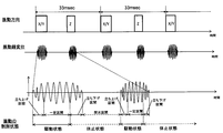
- FIG. 2 is a diagram showing a switching operation of the vibration direction of the vibration weight 342.
- the vibration direction of the vibration weight 342 is intermittently switched between the first axis and the second axis.
- the first axis or the second axis is a direction perpendicular to the planar substrate 341. Further, the first axis and the second axis are orthogonal. Assuming that two rotation axes orthogonal to each other in a plane parallel to the planar substrate 341 are an x axis and ay axis, and a rotation axis perpendicular to the planar substrate 341 is a z axis, in this embodiment, the first axis is the x axis or The y axis is the second axis.
- the angular velocity sensor 100 detects the angular velocities in the z-axis direction and the y-axis direction when vibrating the vibrating weight 342 in the x-axis direction.
- the angular velocity in the z-axis direction refers to an angular velocity that rotates about the z-axis.
- the same definition applies to the angular velocities in the x-axis direction and the y-axis direction.
- X / Y indicates that the vibrating weight 342 is vibrated in the z-axis direction to detect the Coriolis force in the x-axis and y-axis directions
- Z indicates the vibrating weight 342 in the x-axis or y-axis direction. It shows that the Coriolis force in the z-axis direction is detected by vibrating.
- the displacement of the vibration weight 342 is divided into a rising section, a fixed section, a falling section, and an intermittent section.
- the start-up section refers to a section from when the drive signal from the ASIC 330 is input to the MEMS 340 and the vibration weight 342 starts vibrating until the amplitude becomes constant.
- the fixed section refers to a section in which the drive signal from the ASIC 330 is input to the MEMS 340 and the vibrating weight 342 vibrates with a constant amplitude.
- the falling section refers to a section from when the input of the drive signal from the ASIC 330 to the MEMS 340 is completed until the vibration weight 342 is no longer vibrated.
- the intermittent section is a section where there is no vibration of the vibrating weight 342. That is, the intermittent section refers to a section from the end of the falling section to the start of the next starting section.
- the vibration control state of the vibration weight 342 is divided into a driving state and a resting state.
- the driving state is a state in which the vibration weight 342 is driven by a driving signal, and indicates a start-up section and a constant section.
- the driving state is a state in which a driving signal is input from the driving circuit 130 to at least one of the first vibrating unit 111 and the second vibrating unit 112 described later.
- the resting state is a state in which the vibrating weight 342 is not driven by the driving signal, and indicates a falling section and an intermittent section. Further, the resting state is a state in which a drive signal from the drive circuit 130 is not input to any of the first vibrating unit 111 and the second vibrating unit 112 described later.
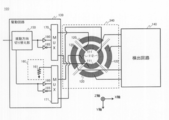
- FIG. 3 is a diagram illustrating a configuration example of the angular velocity sensor 100 according to the embodiment of the present invention.
- the angular velocity sensor 100 of this example includes a MEMS 340, a drive circuit 130, and a detection circuit 140.
- the drive circuit 130 and the detection circuit 140 are provided in the ASIC 330.
- the angular velocity sensor 100 detects the angular velocity based on the Coriolis force according to the vibration of the vibrating weight 342 and the angular velocity.
- the drive circuit 130 outputs a drive signal for vibrating the MEMS 340 to the first axis or the second axis to the MEMS 340.
- the first axis and the second axis may be an x-axis and a z-axis, respectively.
- the plane of the planar substrate 341 is an xy plane.
- FIG. 3 shows the upper surface of the MEMS 340.
- the MEMS 340 includes a vibrating weight 342, a first vibrating unit 111, a second vibrating unit 112, and an output unit 120.
- the first vibrating portion 111 and the second vibrating portion 112 correspond to the drive electrode 346 shown in FIG.
- the first vibrating unit 111 and the second vibrating unit 112 may be collectively referred to simply as a vibrating unit.
- the output unit 120 corresponds to the detection electrode 347 shown in FIG.
- the first vibrating unit 111 vibrates the vibrating weight 342 about the first axis.
- the second vibrating unit 112 vibrates the vibrating weight 342 about the second axis.
- the output unit 120 detects a signal generated according to the vibration of the vibration weight 342.
- the output unit 120 outputs a signal based on the angular velocity and the Coriolis force generated by the vibration of the vibrating weight 342.
- the output unit 120 of this example outputs an electrical signal obtained by converting the Coriolis force by the piezoelectric body 345. Since the output unit 120 includes four electrodes arranged on the x-axis and the y-axis, the output unit 120 can output a Coriolis force in the three-axis direction.
- the detection circuit 140 processes the output from the output unit 120.
- the detection circuit 140 can detect the angular velocity based on the output from the output unit 120. Specifically, the angular velocity is detected from the relationship between the signal based on the Coriolis force output from the output unit 120 and the drive signal output from the drive circuit 130.
- the drive circuit 130 includes a vibration direction switching unit 150, a first vibration attenuation unit 160, a first switch unit 170, and a second switch unit 171.
- the vibration direction switching unit 150 is connected to the first vibration unit 111 via the first switch unit 170 and the first switch unit 170. Further, the vibration direction switching unit 150 is connected to the second vibration unit 112 via the second switch unit 171.
- the vibration direction switching unit 150 switches driving of the first vibration unit 111 and the second vibration unit 112. Accordingly, the vibration direction switching unit 150 switches the vibration direction of the vibration weight 342 from one of the first axis and the second axis to the other.
- the vibration direction switching unit 150 may switch the vibration direction of the vibration weight 342 by controlling the first switch unit 170 and the second switch unit 171.
- the normal rotation buffer 180 and the reverse buffer 185 are connected in parallel between the vibration direction switching unit 150 and the first switch unit 170. That is, signals having the same phase and opposite phase as the output of the vibration direction switching unit 150 are input to the first switch unit 170.
- the first switch unit 170 selects and connects the normal buffer 180 and the reverse buffer 185 to each drive electrode of the first vibrating unit 111.
- the second switch unit 171 switches ON / OFF of the conduction of the first vibration damping unit 160 and the second vibration unit 112.
- the second switch unit 171 of this example selects and connects any one of the normal rotation buffer 180, the reverse buffer 185, and the first vibration attenuation unit 160 to each drive electrode of the second vibration unit 112. It is a multiplexer.
- the first vibration unit 111 includes a pair of drive electrodes arranged along the y-axis and facing each other with the center of the flat substrate 341 interposed therebetween.
- the second vibration unit 112 includes a pair of drive electrodes arranged along the x-axis and facing each other with the center of the planar substrate 341 interposed therebetween. For example, when the vibrating weight 342 is vibrated in the x-axis direction, signals having opposite phases are input to the two drive electrodes of the second vibrating unit 112. At this time, no signal is input to each drive electrode of the first vibrating section 111.
- the vibrating weight 342 when the vibrating weight 342 is vibrated in the z-axis direction, signals having the same phase are input to the drive electrodes of the first vibrating unit 111 and the second vibrating unit 112.
- the forward rotation buffer 180 is connected to each drive electrode.
- the second switch unit 171 synchronizes the second vibration unit 112 with the second vibration unit 160 via the second switch unit 171 in synchronization with the timing at which the second vibration unit 112 switches from the driving state to the dormant state.
- the first vibration attenuation unit 160 is connected to the second vibration unit 112 and attenuates the vibration of the vibration weight 342. Thereby, the falling section of the vibration of the second vibration unit 112 is shortened.
- the second switch unit 171 switches the conduction between the first vibration attenuation unit 160 and the vibration unit from ON to OFF in synchronization with the timing at which the second vibration unit 112 is switched from the resting state to the driving state. And the 2nd switch part 171 inputs a drive signal into each drive electrode of a vibration part. Thus, energy is prevented from being consumed by the first vibration attenuating unit 160 in the driving state.
- the first vibration unit 111 and the second vibration unit 112 electrically consume the kinetic energy of the vibration weight 342 before switching the vibration direction of the vibration weight 342.
- the first vibration attenuation unit 160 attenuates vibration by electrically consuming kinetic energy.
- the first vibration damping unit 160 includes a damping resistor 161. That is, the first vibration attenuating unit 160 does not require a special circuit or the like, so that it is not necessary to consume useless power.
- the vibration direction switching unit 150 switches the driving by providing a pause period during which the driving of the first vibrating unit 111 and the second vibrating unit 112 is paused while switching the vibration direction of the vibrating weight 342. Thereby, it can suppress that the vibration of a 1st axis
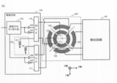
- FIG. 4 is a diagram showing a configuration example of the angular velocity sensor 100 according to the embodiment of the present invention.
- the first vibration attenuation unit 160 is connected to the first switch unit 170 in addition to the second switch unit 171 as compared with the embodiment of FIG. It is different.
- the first vibration attenuation unit 160 is connected to the first vibration unit 111 and the second vibration unit 112 via the first switch unit 170 and the second switch unit 171.
- the first switch unit 170 switches ON / OFF of conduction between the first vibration attenuation unit 160 and the first vibration unit 111.
- the second switch unit 171 switches ON / OFF of conduction between the first vibration attenuation unit 160 and the second vibration unit 112.
- the first switch unit 170 and the second switch unit 171 turn off the conduction between the first vibration attenuation unit 160 and the vibration unit in synchronization with the timing at which the vibration unit switches from the driving state to the resting state. Switch to ON.
- the first vibration attenuating unit 160 attenuates the vibration simultaneously with switching from the constant section of vibration to the falling section.
- first switch unit 170 and the second switch unit 171 switch the conduction between the first vibration attenuation unit 160 and the vibration unit from ON to OFF in synchronization with the timing at which the vibration unit switches from the resting state to the driving state. Switch to. And a drive signal is inputted into each drive electrode of a vibration part. Thus, energy is prevented from being consumed by the first vibration attenuating unit 160 in the driving state.
- the angular velocity sensor 100 does not only move before changing the vibration direction from the first axis to the second axis but also before changing the vibration direction from the second axis to the first axis. Energy is consumed by the first vibration damping unit 160. Therefore, the angular velocity sensor 100 can shorten the falling sections of both vibrations in the first axis and the second axis.
- the first vibration attenuation unit 160 has attenuation resistors 161 corresponding to the first switch unit 170 and the second switch unit 171, respectively.
- the damping resistor 161 is set to an optimum resistance value in order to electrically consume kinetic energy in accordance with the first vibrating unit 111 and the second vibrating unit 112.
- FIG. 5 is a diagram illustrating a configuration example of the angular velocity sensor 100 according to the embodiment of the present invention.
- the angular velocity sensor 100 according to the present embodiment is different from the embodiment of FIG. 4 in that a third switch unit 172 is provided instead of the first switch unit 170 and the second switch unit 171.
- FIG. 5 shows a specific configuration example of the detection circuit 140.
- the third switch unit 172 switches ON / OFF of conduction between the first vibration attenuation unit 160 and the first vibration unit 111, and between the first vibration attenuation unit 160 and the second vibration unit 112. As an example, the third switch unit 172 turns on the conduction between the first vibration attenuation unit 160 and the first vibration unit 111 in synchronization with the timing at which the vibration unit switches from the driving state to the resting state or from the resting state to the driving state. Switch between / OFF.
- the third switch unit 172 turns on the conduction between the first vibration attenuation unit 160 and the first vibration unit 111 in synchronization with the timing of switching from the driving state to the resting state. Further, the third switch unit 172 turns off the conduction between the first vibration attenuating unit 160 and the first vibration unit 111 in synchronization with the timing of switching from the resting state to the driving state.
- the first vibration attenuating unit 160 is connected to the first vibrating unit 111 in the falling section of the first axis vibration. Thereby, the falling section in the direction of the first vibration is most shortened.
- the first vibration attenuation unit 160 is connected to the first vibration unit 111 in a suspension state of the first axis vibration. Thereby, the vibration of the vibration weight 342 generated in the intermittent section is attenuated.
- the third switch unit 172 turns ON / OFF the conduction of the first vibration attenuation unit 160 and the second vibration unit 112 in synchronization with the timing at which the vibration unit is switched from the driving state to the resting state or from the resting state to the driving state. Switch.
- the third switch unit 172 turns on the conduction between the first vibration attenuation unit 160 and the second vibration unit 112 in synchronization with the timing of switching from the driving state to the resting state.
- the third switch unit 172 turns off the conduction between the first vibration attenuating unit 160 and the second vibration unit 112 in synchronization with the timing of switching from the rest state to the driving state.
- the first vibration attenuating unit 160 is connected to the second vibrating unit 112 in the falling section of the second axis vibration. Thereby, the falling section in the direction of the second vibration is most shortened.
- the first vibration attenuation unit 160 is connected to the second vibration unit 112 in a suspension state of vibration of the second axis. Thereby, the section where the vibration of the vibration weight 342 generated in the resting state is attenuated becomes the largest.
- the angular velocity sensor 100 can shorten the falling sections of both vibrations in the first axis and the second axis. Further, since the first vibration attenuating unit 160 is connected to the first vibrating unit 111 or the second vibrating unit 112 in the resting state, the vibration of the vibrating weight 342 generated in the resting state is attenuated.
- the detection circuit 140 includes a second vibration attenuation unit 165 and a fourth switch unit 173.
- the fourth switch unit 173 switches ON / OFF of conduction between the second vibration damping unit 165 and the output unit 120.
- the fourth switch unit 173 switches ON / OFF in synchronization with the timing when the vibration unit switches from the driving state to the resting state or from the resting state to the driving state.
- the second vibration attenuation unit 165 is connected to the output unit 120 via the fourth switch unit 173 and consumes the kinetic energy of the vibration weight 342 to attenuate the vibration of the vibration weight 342.
- the output unit 120 of this example has four detection electrodes outside the four drive electrodes.
- the second vibration attenuation unit 165 may be connected to all the detection electrodes in the output unit 120 via the fourth switch unit 173. Thereby, in addition to the 1st vibration attenuation part 160, the 2nd vibration attenuation part 165 can also consume the kinetic energy of the vibration weight 342, Therefore A fall area is shortened.
- the second vibration attenuation unit 165 attenuates vibration by electrically consuming the kinetic energy of the vibration weight 342.
- the second vibration damping unit 165 includes a damping resistor 161. That is, the first vibration attenuating unit 160 does not require a special circuit or the like, so that it is not necessary to consume useless power.
- the drive circuit 130 and the detection circuit 140 include an attenuation resistor 161.
- the detection circuit 140 includes the attenuation resistor 161, the falling section can be shortened.
- 3 and 4 may also include the first vibration attenuation unit 160 or the second vibration attenuation unit 165.
- FIG. 6 is a circuit diagram showing an equivalent circuit of the piezoelectric element.
- the piezoelectric element is an electromechanical conversion element and is represented by a circuit shown in FIG. 6 as an electrical equivalent circuit.
- a piezoelectric capacitor 191, an inductance 192, and a piezoelectric resistor 193 are connected in series between the two terminals 194.
- the electrode capacitor 190 is connected in parallel with the piezoelectric capacitor 191, the inductance 192, and the piezoelectric resistor 193.
- the terminal 194 is a free end at the time of mechanical resonance.
- the electrode capacity 190 is a capacity between the drive electrodes 346.
- the piezoelectric capacitor 191, the inductance 192, and the piezoelectric resistor 193 are equivalent circuits of the piezoelectric body 345.
- a current I flows through the equivalent circuit of the piezoelectric body 345 during mechanical resonance.
- the current I is proportional to the dynamic speed of vibration of the vibrating weight 342.
- FIG. 7 is a circuit diagram showing an equivalent circuit of a piezoelectric element provided with an attenuation resistor 161. 6 is different from the equivalent circuit shown in FIG. 6 in that an attenuation resistor 161 is provided between the terminals 194 in FIG.
- the damping resistor 161 is provided in parallel with the capacitance of the drive electrode 346 connected to the first vibrating unit 111 or the second vibrating unit 112. In this embodiment, since the kinetic energy is also consumed by the damping resistor 161, the speed of the piezoelectric body 345 can be effectively reduced.
- the current I is generated in proportion to the dynamic speed of vibration of the vibration weight 342 and flows to the electrode capacitance 190 and the damping resistor 161 of the drive electrode 346.
- Current I the current I R flowing through the damping resistor 161, divided into a current I P flowing through the electrode capacitance 190. That is, since power is consumed in the damping resistor 161 in addition to the piezoelectric resistor 193, the vibration falling interval can be shortened.
- the resistance value R of the damping resistor 161 may be equal to the absolute value of the impedance of the electrode capacitor 190 of the drive electrode 346 at the resonance frequency of the first vibrating unit 111 or the second vibrating unit 112. In this case, the current I R flowing through the damping resistor 161, the current I P flowing through the electrode capacitance 190 becomes equal, current I R becomes maximum. Therefore, the amount of kinetic energy consumed by the damping resistor 161 and the piezoelectric resistor 193 is maximized.
- the electrode capacitance 190 has been described as the electrode capacitance between the drive electrodes 346.
- the electrode capacitance 190 may be the electrode capacitance of the detection electrode 347.
- each of the drive circuit 130 and the detection circuit 140 When the damping resistor 161 is provided in each of the drive circuit 130 and the detection circuit 140, the electrode capacitance 190 varies depending on the electrode areas of the first vibrating unit 111, the second vibrating unit 112, and the output unit 120. Therefore, when the attenuation resistor 161 corresponding to the absolute value of each impedance of the electrode capacitor 190 is selected, the effect of damping the vibration is high.
- Each attenuation resistor 161 may have an impedance corresponding to the area of the electrode to be connected.
- the angular velocity sensor 100 a piezoelectric element type sensor that vibrates the vibrating weight 342 using the piezoelectric body 345 in the MEMS 340 is used.
- the angular velocity sensor 100 may be a capacitive angular velocity sensor in which the MEMS 340 vibrates the vibrating weight 342 using the electrostatic capacitance. Even if a capacitance type angular velocity sensor is used, the kinetic energy of the vibrating weight 342 can be converted into a current, so that the first vibration attenuating unit 160 can attenuate the vibration.
- SYMBOLS 100 ... Angular velocity sensor, 111 ... 1st vibration part, 112 ... 2nd vibration part, 120 ... Output part, 130 ... Drive circuit, 140 ... Detection circuit, 150 * ..Vibration direction switching unit, 160... First vibration attenuation unit, 161... Damping resistor, 165... Second vibration attenuation unit, 170... First switch unit, 171. Second switch part, 172 ... third switch part, 173 ... fourth switch part, 190 ... electrode capacity, 191 ... piezoelectric capacity, 192 ... inductance, 193 ... Piezoelectric resistance, 194 ... terminal, 300 ... sensor package, 310 ... package substrate, 320 ...
Landscapes
- Engineering & Computer Science (AREA)
- Physics & Mathematics (AREA)
- General Physics & Mathematics (AREA)
- Radar, Positioning & Navigation (AREA)
- Remote Sensing (AREA)
- Signal Processing (AREA)
- Gyroscopes (AREA)
Abstract
L'invention porte sur un capteur de vitesse angulaire, lequel capteur comporte un circuit d'attaque pour générer un signal d'attaque, un poids oscillant, une unité d'oscillation pour amener le poids oscillant à osciller le long d'un premier et d'un second axe en fonction du signal d'attaque, une unité de sortie pour délivrer en sortie un signal qui est basé sur une force de Coriolis générée en fonction d'une vitesse angulaire et de l'oscillation du poids oscillant, un circuit de détection pour détecter la vitesse angulaire à partir du signal qui est basé sur la force de Coriolis, et une première unité d'amortissement d'oscillation qui consomme électriquement l'énergie cinétique du poids oscillant.
Priority Applications (2)
| Application Number | Priority Date | Filing Date | Title |
|---|---|---|---|
| JP2015508013A JP6067102B2 (ja) | 2013-03-29 | 2014-03-07 | 角速度センサ |
| US14/858,044 US20160003616A1 (en) | 2013-03-29 | 2015-09-18 | Angular velocity sensor |
Applications Claiming Priority (2)
| Application Number | Priority Date | Filing Date | Title |
|---|---|---|---|
| JP2013073836 | 2013-03-29 | ||
| JP2013-073836 | 2013-03-29 |
Related Child Applications (1)
| Application Number | Title | Priority Date | Filing Date |
|---|---|---|---|
| US14/858,044 Continuation US20160003616A1 (en) | 2013-03-29 | 2015-09-18 | Angular velocity sensor |
Publications (1)
| Publication Number | Publication Date |
|---|---|
| WO2014155997A1 true WO2014155997A1 (fr) | 2014-10-02 |
Family
ID=51623018
Family Applications (1)
| Application Number | Title | Priority Date | Filing Date |
|---|---|---|---|
| PCT/JP2014/001298 Ceased WO2014155997A1 (fr) | 2013-03-29 | 2014-03-07 | Capteur de vitesse angulaire |
Country Status (3)
| Country | Link |
|---|---|
| US (1) | US20160003616A1 (fr) |
| JP (1) | JP6067102B2 (fr) |
| WO (1) | WO2014155997A1 (fr) |
Cited By (1)
| Publication number | Priority date | Publication date | Assignee | Title |
|---|---|---|---|---|
| WO2017183646A1 (fr) * | 2016-04-21 | 2017-10-26 | 富士フイルム株式会社 | Capteur composite |
Families Citing this family (4)
| Publication number | Priority date | Publication date | Assignee | Title |
|---|---|---|---|---|
| US10648811B2 (en) * | 2017-12-01 | 2020-05-12 | Northrop Grumman Systems Corporation | Vibrating-mass gyroscope system |
| KR102031909B1 (ko) * | 2018-03-19 | 2019-10-14 | 한국생산기술연구원 | Mems 구동 회로 |
| DE102020206003A1 (de) * | 2020-05-13 | 2021-11-18 | Robert Bosch Gesellschaft mit beschränkter Haftung | Verfahren zum Betreiben eines mikroelektromechanischen Gyroskops, Gyroskop |
| EP4187203B1 (fr) * | 2021-11-30 | 2024-10-23 | STMicroelectronics S.r.l. | Dispositif de gyroscope mems à démarrage à chaud amélioré et procédé correspondant |
Citations (4)
| Publication number | Priority date | Publication date | Assignee | Title |
|---|---|---|---|---|
| JP2006342864A (ja) * | 2005-06-08 | 2006-12-21 | Toyota Motor Corp | 振動抑制装置 |
| JP2008108762A (ja) * | 2006-10-23 | 2008-05-08 | Railway Technical Res Inst | 圧電材とその製造方法、制振装置及び駆動装置 |
| JP2011099818A (ja) * | 2009-11-09 | 2011-05-19 | Yamaha Corp | 振動型角速度センサ |
| JP2012037499A (ja) * | 2010-08-06 | 2012-02-23 | Samsung Electro-Mechanics Co Ltd | ジャイロセンサ駆動装置 |
Family Cites Families (11)
| Publication number | Priority date | Publication date | Assignee | Title |
|---|---|---|---|---|
| JP4655511B2 (ja) * | 2004-05-31 | 2011-03-23 | トヨタ自動車株式会社 | 圧電式制振装置の構成方法 |
| US7950281B2 (en) * | 2007-02-28 | 2011-05-31 | Infineon Technologies Ag | Sensor and method for sensing linear acceleration and angular velocity |
| FR2962532B1 (fr) * | 2010-07-07 | 2013-11-29 | Commissariat Energie Atomique | Capteur inertiel de rotations a disque oscillant |
| KR101318810B1 (ko) * | 2010-09-20 | 2013-10-17 | 페어차일드 세미컨덕터 코포레이션 | 관성 센서 모드 튜닝 회로 |
| WO2012131682A1 (fr) * | 2011-03-31 | 2012-10-04 | Ramot At Tel-Aviv University Ltd. | Structures flexibles dotées d'un moment d'inertie variant dans le temps |
| US9091541B2 (en) * | 2011-10-27 | 2015-07-28 | Thales Holdings Uk Plc | Compass |
| FR2985029B1 (fr) * | 2011-12-22 | 2014-10-24 | Commissariat Energie Atomique | Dispositif micro/nano capteur inertiel multiaxial de mouvements |
| KR101388762B1 (ko) * | 2012-09-21 | 2014-04-25 | 삼성전기주식회사 | 관성 센서 및 그 보정 방법 |
| EP2746724B1 (fr) * | 2012-12-20 | 2017-02-22 | Tronics Microsystems S.A. | Gyroscope micromécanique |
| JP5988494B2 (ja) * | 2013-02-04 | 2016-09-07 | 富士フイルム株式会社 | 角速度センサ及びその製造方法 |
| US9360319B2 (en) * | 2013-09-05 | 2016-06-07 | Freescale Semiconductor, Inc. | Multiple sense axis MEMS gyroscope having a single drive mode |
-
2014
- 2014-03-07 WO PCT/JP2014/001298 patent/WO2014155997A1/fr not_active Ceased
- 2014-03-07 JP JP2015508013A patent/JP6067102B2/ja not_active Expired - Fee Related
-
2015
- 2015-09-18 US US14/858,044 patent/US20160003616A1/en not_active Abandoned
Patent Citations (4)
| Publication number | Priority date | Publication date | Assignee | Title |
|---|---|---|---|---|
| JP2006342864A (ja) * | 2005-06-08 | 2006-12-21 | Toyota Motor Corp | 振動抑制装置 |
| JP2008108762A (ja) * | 2006-10-23 | 2008-05-08 | Railway Technical Res Inst | 圧電材とその製造方法、制振装置及び駆動装置 |
| JP2011099818A (ja) * | 2009-11-09 | 2011-05-19 | Yamaha Corp | 振動型角速度センサ |
| JP2012037499A (ja) * | 2010-08-06 | 2012-02-23 | Samsung Electro-Mechanics Co Ltd | ジャイロセンサ駆動装置 |
Cited By (1)
| Publication number | Priority date | Publication date | Assignee | Title |
|---|---|---|---|---|
| WO2017183646A1 (fr) * | 2016-04-21 | 2017-10-26 | 富士フイルム株式会社 | Capteur composite |
Also Published As
| Publication number | Publication date |
|---|---|
| JPWO2014155997A1 (ja) | 2017-02-16 |
| JP6067102B2 (ja) | 2017-01-25 |
| US20160003616A1 (en) | 2016-01-07 |
Similar Documents
| Publication | Publication Date | Title |
|---|---|---|
| KR101641066B1 (ko) | 진동 마이크로-기계식 각속도 센서 | |
| US9709595B2 (en) | Method and apparatus for detecting linear and rotational movement | |
| US10309782B2 (en) | Quality factor estimation for resonators | |
| US8631700B2 (en) | Resonating sensor with mechanical constraints | |
| JP6067102B2 (ja) | 角速度センサ | |
| JP6575129B2 (ja) | 振動型角速度センサ | |
| JP6538967B2 (ja) | 自動車用の超ロバスト2軸回転速度センサ | |
| JP5205725B2 (ja) | 角速度センサ | |
| WO2011074099A1 (fr) | Dispositif de détection de vitesse angulaire | |
| JP2017020977A (ja) | センサ装置 | |
| JP5360020B2 (ja) | 角速度センサ | |
| JP5018337B2 (ja) | 音叉振動型センサ、力学量検出装置、及び力学量検出方法 | |
| WO2018003692A1 (fr) | Capteur de grandeur physique | |
| JP5397171B2 (ja) | 振動型角速度センサ | |
| WO2019017277A1 (fr) | Capteur de vitesse angulaire de type à vibration | |
| JP4362739B2 (ja) | 振動型角速度センサ | |
| JP2010169498A (ja) | 角速度センサ素子 | |
| JP2005283584A (ja) | 駆動/検出手段、駆動ユニットおよび評価ユニットを有するセンサ | |
| JP6604158B2 (ja) | 振動型角速度センサ | |
| JP2010230346A (ja) | 角速度センサ | |
| JP2017187445A (ja) | 角速度センサおよびその感度調整方法 | |
| JP6657842B2 (ja) | 角速度センサ装置 | |
| US20130255376A1 (en) | Inertial sensor and measuring method for measuring angular velocity using the same | |
| CN106415204B (zh) | 振动型角速度传感器 | |
| JP6189792B2 (ja) | 角速度センサ |
Legal Events
| Date | Code | Title | Description |
|---|---|---|---|
| 121 | Ep: the epo has been informed by wipo that ep was designated in this application |
Ref document number: 14774494 Country of ref document: EP Kind code of ref document: A1 |
|
| ENP | Entry into the national phase |
Ref document number: 2015508013 Country of ref document: JP Kind code of ref document: A |
|
| NENP | Non-entry into the national phase |
Ref country code: DE |
|
| 122 | Ep: pct application non-entry in european phase |
Ref document number: 14774494 Country of ref document: EP Kind code of ref document: A1 |