WO2014156178A1 - Dispositif de génération de puissance thermoélectrique et procédé de génération de puissance thermoélectrique - Google Patents
Dispositif de génération de puissance thermoélectrique et procédé de génération de puissance thermoélectrique Download PDFInfo
- Publication number
- WO2014156178A1 WO2014156178A1 PCT/JP2014/001806 JP2014001806W WO2014156178A1 WO 2014156178 A1 WO2014156178 A1 WO 2014156178A1 JP 2014001806 W JP2014001806 W JP 2014001806W WO 2014156178 A1 WO2014156178 A1 WO 2014156178A1
- Authority
- WO
- WIPO (PCT)
- Prior art keywords
- power generation
- thermoelectric power
- thermoelectric
- generation unit
- temperature
- Prior art date
- Legal status (The legal status is an assumption and is not a legal conclusion. Google has not performed a legal analysis and makes no representation as to the accuracy of the status listed.)
- Ceased
Links
Images








Classifications
-
- B—PERFORMING OPERATIONS; TRANSPORTING
- B21—MECHANICAL METAL-WORKING WITHOUT ESSENTIALLY REMOVING MATERIAL; PUNCHING METAL
- B21B—ROLLING OF METAL
- B21B45/00—Devices for surface or other treatment of work, specially combined with or arranged in, or specially adapted for use in connection with, metal-rolling mills
-
- H—ELECTRICITY
- H10—SEMICONDUCTOR DEVICES; ELECTRIC SOLID-STATE DEVICES NOT OTHERWISE PROVIDED FOR
- H10N—ELECTRIC SOLID-STATE DEVICES NOT OTHERWISE PROVIDED FOR
- H10N10/00—Thermoelectric devices comprising a junction of dissimilar materials, i.e. devices exhibiting Seebeck or Peltier effects
- H10N10/10—Thermoelectric devices comprising a junction of dissimilar materials, i.e. devices exhibiting Seebeck or Peltier effects operating with only the Peltier or Seebeck effects
- H10N10/17—Thermoelectric devices comprising a junction of dissimilar materials, i.e. devices exhibiting Seebeck or Peltier effects operating with only the Peltier or Seebeck effects characterised by the structure or configuration of the cell or thermocouple forming the device
-
- H—ELECTRICITY
- H10—SEMICONDUCTOR DEVICES; ELECTRIC SOLID-STATE DEVICES NOT OTHERWISE PROVIDED FOR
- H10N—ELECTRIC SOLID-STATE DEVICES NOT OTHERWISE PROVIDED FOR
- H10N10/00—Thermoelectric devices comprising a junction of dissimilar materials, i.e. devices exhibiting Seebeck or Peltier effects
- H10N10/10—Thermoelectric devices comprising a junction of dissimilar materials, i.e. devices exhibiting Seebeck or Peltier effects operating with only the Peltier or Seebeck effects
- H10N10/13—Thermoelectric devices comprising a junction of dissimilar materials, i.e. devices exhibiting Seebeck or Peltier effects operating with only the Peltier or Seebeck effects characterised by the heat-exchanging means at the junction
-
- B—PERFORMING OPERATIONS; TRANSPORTING
- B21—MECHANICAL METAL-WORKING WITHOUT ESSENTIALLY REMOVING MATERIAL; PUNCHING METAL
- B21B—ROLLING OF METAL
- B21B1/00—Metal-rolling methods or mills for making semi-finished products of solid or profiled cross-section; Sequence of operations in milling trains; Layout of rolling-mill plant, e.g. grouping of stands; Succession of passes or of sectional pass alternations
- B21B1/46—Metal-rolling methods or mills for making semi-finished products of solid or profiled cross-section; Sequence of operations in milling trains; Layout of rolling-mill plant, e.g. grouping of stands; Succession of passes or of sectional pass alternations for rolling metal immediately subsequent to continuous casting
-
- Y—GENERAL TAGGING OF NEW TECHNOLOGICAL DEVELOPMENTS; GENERAL TAGGING OF CROSS-SECTIONAL TECHNOLOGIES SPANNING OVER SEVERAL SECTIONS OF THE IPC; TECHNICAL SUBJECTS COVERED BY FORMER USPC CROSS-REFERENCE ART COLLECTIONS [XRACs] AND DIGESTS
- Y02—TECHNOLOGIES OR APPLICATIONS FOR MITIGATION OR ADAPTATION AGAINST CLIMATE CHANGE
- Y02P—CLIMATE CHANGE MITIGATION TECHNOLOGIES IN THE PRODUCTION OR PROCESSING OF GOODS
- Y02P70/00—Climate change mitigation technologies in the production process for final industrial or consumer products
- Y02P70/10—Greenhouse gas [GHG] capture, material saving, heat recovery or other energy efficient measures, e.g. motor control, characterised by manufacturing processes, e.g. for rolling metal or metal working
Definitions
- the present invention relates to a thermoelectric power generation apparatus that converts thermal energy generated by radiation of a steel material into electric energy and recovers it, and a thermoelectric power generation method using the same.
- Patent Document 1 describes a method in which a heat receiving device is disposed facing a high-temperature object, and the thermal energy of the high-temperature object is converted into electric energy and recovered.
- Patent Document 2 describes a method of recovering heat energy processed as waste heat by bringing a thermoelectric element module into contact with the heat energy and converting it into electrical energy.
- Patent Document 1 Although there is a description that it can be applied to a slab continuous casting line, the temperature distribution of the slab in actual operation and the fluctuation of the released heat quantity (thermal energy) due to the fluctuation of the slab quantity, etc. Variations are not considered at all.
- patent document 2 since it is necessary to fix a module with respect to a heat source, there exists a problem that a module cannot be installed with respect to the moving heat source.
- the thermoelectric power generation device in the unsteady state where the front or rear end of the steel material is a heat source, the thermoelectric power generation device can only be installed far away from the steel material in order to prevent damage to the device due to fluctuations in the height of the steel material. It cannot be installed. And if it was installed far away from the steel material, there was a problem that the thermal energy of the high-temperature object could not be transmitted well to the thermoelectric generator and the electrical energy could not be converted efficiently.
- the present invention has been developed in view of the above-described situation, and in various manufacturing processes, particularly in a continuous casting line or a slab continuous casting line where the heat source flows, there is a variation in the state of generation of the heat source during operation. Even if it exists, it aims at providing the thermoelectric power generation apparatus provided with the thermoelectric power generation unit provided with the thermoelectric power generation unit which can convert
- thermoelectric generator that can efficiently use heat in a steel production line, together with a thermoelectric generation method using it.
- the present invention is based on the above findings.
- thermoelectric power generation apparatus including a thermoelectric power generation unit that converts thermal energy generated by radiation of steel materials into electrical energy
- the thermoelectric power generator is a thermoelectric power generator having moving means capable of integrally moving the thermoelectric power generation unit.
- thermoelectric power generation apparatus according to 1, wherein the thermoelectric power generation unit faces the steel material and is installed according to the output of the thermoelectric power generation unit.
- thermoelectric power generator according to 1 or 2, wherein the thermoelectric power generation unit is installed close to a low temperature part with a lower output than a high temperature part with a higher output according to the output of the thermoelectric power generation unit.
- thermoelectric generator according to any one of 1 to 3, wherein the thermoelectric power generation module or the thermoelectric element in the thermoelectric power generation unit is densely arranged in a high temperature portion where the output is higher than a low temperature portion where the output is low, according to the output of the thermoelectric power generation unit. Power generation device.
- thermoelectric power generator according to any one of 1 to 4, wherein the thermoelectric power generator includes a heat reflecting material.
- thermoelectric power generator according to any one of 1 to 5, wherein the thermoelectric power generation unit is further installed according to the temperature of the thermoelectric power generation unit and / or the temperature of the steel material.
- thermoelectric generator In accordance with the temperature and / or output obtained by measuring at least one of the temperature of the steel material, the temperature of the thermoelectric power generation unit, and the output of the thermoelectric power generation unit, the moving means, the thermoelectric power generation unit and the steel material, the thermoelectric generator according to any one of 1 to 6, which is a moving means for controlling the distance of the power.
- thermoelectric power generation device according to any one of 1 to 7, wherein the thermoelectric power generation device has a shape surrounding an outer periphery of the steel material.
- thermoelectric generator according to any one of 1 to 8, wherein the thermoelectric generator is provided with at least one opening.
- thermoelectric power generation method for performing thermoelectric power generation by receiving heat of a steel material using the thermoelectric power generation device according to any one of 1 to 9 above.
- thermoelectric power generation unit includes a mechanism for monitoring the temperature of the thermoelectric power generation unit, and when the temperature monitored by the mechanism reaches the allowable temperature of the thermoelectric power generation unit, the temperature of the thermoelectric power generation unit is reduced to the allowable temperature or less.
- thermoelectric generator according to 11, wherein the monitoring mechanism includes a thermocouple, and the thermocouple is disposed at a position where the temperature of the heat receiving plate of the thermoelectric generator unit is measured.
- thermoelectric power generation apparatus wherein the thermoelectric power generation unit is installed in accordance with a temperature and / or output of the thermoelectric power generation unit facing a steel material.
- thermoelectric power generation method using the thermoelectric power generation device according to any one of 11 to 13 above, receiving heat from a steel material to generate power, and using the generated electric energy to move a thermoelectric power generation unit of the thermoelectric power generation device.
- thermoelectric power generation unit and the heat source can be held at a distance where the power generation efficiency is good, the power generation efficiency is improved, and the thermal energy generated from the production line is at a higher level than in the past. It can be recovered.
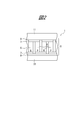
- thermoelectric power generator which shows one Embodiment of this invention.
- thermoelectric power generator which shows one Embodiment of this invention.
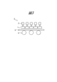
- thermoelectric generator which shows one Embodiment of this invention.
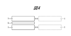
- other thermoelectric generator which shows one Embodiment of this invention.
- FIG. 1 shows the example of installation of the thermoelectric power generator according to one Embodiment of this invention.
- FIG. 1 shows the other installation place of the thermoelectric power generator according to one Embodiment of this invention.
- thermoelectric power generator according to one Embodiment of this invention.
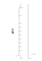
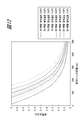
- thermoelectric power generation unit It is the graph showing the relationship of the power generation output ratio with respect to the distance of steel materials and a thermoelectric power generation unit. It is a figure which shows the example of installation of the thermoelectric power generation unit according to this invention. It is sectional drawing which shows the example of arrangement
- (A) And (b) is a figure which shows the example of installation of the thermoelectric power generator with a reflecting material according to this invention.
- A) And (b) is a figure which shows the other example of installation of the thermoelectric generator with a reflecting material according to this invention.
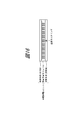
- or (D) is a figure which shows the other example of installation of the thermoelectric power generation unit according to this invention. It is a figure which shows the example which attached the temperature monitoring mechanism to the thermoelectric power generation unit.
- FIG. 1 is a schematic diagram for explaining an embodiment of a thermoelectric generator of the present invention.
- 1 is a thermoelectric generator unit
- 2 is a moving means
- 3 is a thermoelectric generator
- 4 is a table roller
- 5 is a steel material.
- the thermoelectric power generation device 3 includes a thermoelectric power generation unit 1 disposed opposite to a steel material 5 as a heat source, and a moving means 2 for the thermoelectric power generation unit.
- the steel material 5 is on the upper surface of the table roller.
- the steel material in the present invention is not particularly limited as long as it is an iron-based metal heated to a temperature of about 600 to 1300 ° C. at a steel mill or a processing factory.
- Preferable examples include slabs, rough bars, hot-rolled steel strips in rolling mills, and strips and pipes in forged pipe facilities, and other steel pipes, steel bars, wire rods, and rails such as rails (hereinafter simply referred to as steel materials).
- the thermoelectric generator of the present invention includes at least one thermoelectric generator unit in the width direction and the longitudinal direction of the steel material.
- the thermoelectric power generation unit includes a heat receiving means facing the steel material, at least one thermoelectric power generation module, and a heat radiating means.
- the heat receiving means depends on the material, the temperature on the high temperature side of the thermoelectric element is several to several tens of degrees, and in some cases, the temperature is about several hundred degrees. Therefore, the heat receiving means only needs to have heat resistance and durability at the temperature.
- general steel materials can be used in addition to copper, copper alloys, aluminum, aluminum alloys, ceramics, and carbon.
- the heat dissipating means may be a conventionally known means and is not particularly limited, but has a cooling device equipped with fins, a water cooling device utilizing contact heat transfer, a heat sink utilizing boiling heat transfer, and a refrigerant flow path.
- the water-cooled plate etc. which were done are illustrated as a preferable form.
- the low temperature side of the thermoelectric power generation unit is water cooled by spray cooling or the like, the low temperature side is efficiently cooled.
- the thermoelectric generator unit is installed below the heat source, even if spray cooling is applied, if the spray is properly placed, the remaining water will fall under the table and cool the high temperature side of the thermoelectric generator unit. Without this, the low temperature side of the thermoelectric generator unit is efficiently cooled.
- spray cooling is performed, the side to be cooled by contact with the spray refrigerant is the heat dissipating means.
- the thermoelectric power generation module 8 used in the present invention has a two-dimensional thermoelectric element group in which P-type and N-type semiconductors which are thermoelectric elements 6 are connected by several tens to thousands of electrodes 7. And insulating materials 9 arranged on both sides thereof.
- the thermoelectric power generation module 8 may include a heat conductive sheet or a protection plate on both sides or one side. Further, each of the protective plates may serve as the heat receiving means 10 and the heat radiating means 11. When the cooling plate itself, which is the heat receiving means 10 and / or the heat radiating means 11, is an insulating material, or the surface is covered with an insulating material, the insulating material 9 may be substituted.
- thermoelectric power generation unit 6 is a thermoelectric element
- 7 is an electrode
- 9 is an insulating material
- 8 is a thermoelectric power generation module
- 10 is a heat receiving means
- 11 is a heat dissipation means.
- the thermal contact resistance between members is reduced between the heat receiving means and the thermoelectric power generation module, between the heat dissipation means and the thermoelectric power generation module, and between the insulating material and the protective plate, and the thermoelectric power generation efficiency is further improved.
- the above-described heat conductive sheet can be provided.
- the heat conductive sheet has a predetermined thermal conductivity, and is not particularly limited as long as it is a sheet that can be used in the environment where the thermoelectric power generation module is used. Examples thereof include a graphite sheet.
- the size of the thermoelectric power generation module according to the present invention is preferably 1 ⁇ 10 ⁇ 2 m 2 or less.
- thermoelectric power generation module can be suppressed by setting the size of the module to the above level. More preferably, it is 2.5 ⁇ 10 ⁇ 3 m 2 or less.
- the size of the thermoelectric power generation unit is preferably 1 m 2 or less. This is because, by setting the unit to 1 m 2 or less, it is possible to suppress the deformation of the thermoelectric power generation modules and the thermoelectric power generation unit itself. More preferably, it is 2.5 ⁇ 10 ⁇ 1 m 2 or less.
- the thermoelectric power generation apparatus has a moving means capable of integrally moving the thermoelectric power generation unit, and the distance between the thermoelectric power generation unit and the steel material can be controlled by this moving means.
- the distance control is preferably performed using a power cylinder.
- the moving means as shown in FIGS. 1 and 3, one that can move the thermoelectric generator unit up and down integrally is mentioned. Moreover, even if it can move back and forth and left and right, it can be used without any particular problem. Where the temperature fluctuation is small, the means for controlling the distance is, for example, a thermoelectric power generation unit fixed with a bolt or a thermoelectric power generation unit fixed with a sliding bolt, and the bolt is loosened.
- the moving means may be a manual moving means such as moving the thermoelectric power generation unit by moving the thermoelectric generation unit after tightening it again.
- the moving means may be a moving means for controlling a sliding type movement as shown in FIG. 4 or an opening / closing type movement as shown in FIG.
- spray cooling device itself may or may not be moved integrally with the thermoelectric power generation unit or the like.
- thermoelectric power generation unit installed according to the output of the thermoelectric power generation unit facing steel materials.
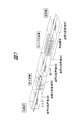
- a thermoelectric power generation unit is placed at any position on the upstream side of the slab cutting device 17 of the continuous casting device, in the slab cutting device, the lower surface of the slab cutting device, or the exit side of the slab cutting device (A in the figure). ), Or as shown in FIG. 7, any position (B to F in the figure) from the rough rolling mill to the hot rolling steel strip conveyance path through the finish rolling mill, and further, as shown in FIG.
- Heat source in actual operation by installing it in the steel sheet conveying path (G in the figure) and the pipe material conveying path (H in the figure) from the heating furnace of the tube connection line to the forming and forging machine according to the temperature of each steel material More efficient power generation can be performed in response to temperature fluctuations.
- 12 is a ladle
- 13 is a tundish
- 14 is a mold
- 15 is a slab cooling device
- 16 is a group of rollers such as straightening rolls
- 17 is a slab cutting device
- 18 is a thermometer
- 19 is a thermoelectric generator.
- 20 are dummy bar tables.
- 21 is a steel plate
- 22 is a pipe
- 23 is a heating furnace
- 24 is a forming and forging machine
- 25 is a hot reducer
- 26 is a rotary hot saw
- 27 is a cooling bed
- 28 is a sizer
- 29 is a straightener. It is.
- the temperature of the steel material is similar to a certain extent depending on the size and type, and therefore the installation location of the thermoelectric power generation unit can be set in advance for each size and type. Further, the installation position of the thermoelectric power generation unit may be set in advance according to the size and product type from the output power predicted value predicted from the output power performance for each thermoelectric power generation unit and / or the temperature. In addition, the distance between the thermoelectric power generation unit and the steel material that is the heat source and the arrangement of the thermoelectric power generation modules in the thermoelectric power generation unit may be determined when the equipment is introduced. In addition, installation of the thermoelectric power generation device (thermoelectric power generation unit) in the present invention can be installed not only above the steel material but also below and side surfaces, and the installation location is not limited to one location, and may be a plurality of locations.
- thermometer 18 is installed in the upstream of the thermoelectric generator 19, and the distance of a thermoelectric generation unit and steel materials is controlled according to the measured value of this thermometer. be able to.
- thermoelectric power generation in response to the temperature fluctuation and the like, so the efficiency of thermoelectric power generation is improved. Further improvement.
- thermometer is preferably a non-contact type such as a radiation thermometer.
- a thermometer is installed on the line and measured automatically and periodically.
- the operator may perform measurement manually. And if the relationship between the temperature of steel materials and the distance with the most efficient thermoelectric power generation is calculated
- thermoelectric power generation unit it is also possible to control the distance between the thermoelectric power generation unit and the steel material according to the output of the thermoelectric power generation unit. That is, the distance between the thermoelectric power generation unit and the steel material as the heat source is adjusted so that the power generation output is increased. At that time, an actual measurement output may be used, or an output value predicted from the temperature of the steel material may be used.
- FIG. 9 shows the relationship between the distance of the thermoelectric power generation unit from the steel material and the power generation output ratio when the power generation output ratio at the rated output is 1. It shows as a result of investigating the thermoelectric generation module interval in the unit and the temperature of the steel as parameters. From the figure, when using a thermoelectric generator equipped with a thermoelectric generator unit in which 50 mm square thermoelectric generator modules are installed at intervals of 70 mm, when the temperature of the steel material is 950 ° C., the distance between the thermoelectric generator unit and the steel material is 340 mm.
- thermoelectric power generation unit in the case of 900 ° C., it is understood that when it is moved to 160 mm and installed, the power generation output ratio becomes 1, and efficient thermoelectric power generation can be performed. That is, in the present invention, it is preferable to obtain the relationship as shown in FIG. 9 and set the distance so that the power generation output ratio in the figure is 1 (rated output). As described above, it is preferable to set the output of the thermoelectric power generation unit so as to be the rated output, but it is necessary to set the upper limit of the thermoelectric power generation unit in consideration of the thermoelectric power generation unit so as not to break the thermoelectric element. When the upper limit of the heat-resistant temperature is taken into consideration, the target of the power generation output ratio can be appropriately reduced, but is preferably set to about 0.7.
- the thermoelectric power generation unit includes a temperature of a steel material (hereinafter, including a temperature at a position facing the thermoelectric power generation unit, a temperature suitable for temperature measurement, and a temperature in the vicinity thereof)
- a temperature of a steel material hereinafter, including a temperature at a position facing the thermoelectric power generation unit, a temperature suitable for temperature measurement, and a temperature in the vicinity thereof.
- the distance according to the form factor, the temperature of the thermoelectric power generation unit, and the output it can be installed closer to the low temperature part with the lower output than the high temperature part with the higher output.
- Such an installation is particularly suitable for continuous lines with little change in temperature.
- thermoelectric power generation unit can be further improved. For example, when the distance between the unit and the steel material is moved to 340 mm in the central portion of FIG. 10 and the distance is moved to 160 mm at the end portion of the steel material, thermoelectric power generation can be performed efficiently.
- the temperature distribution in the width direction of the steel material is often abruptly reduced at a position corresponding to about twice the plate thickness from the width of the steel (hereinafter referred to as the width end) compared to the center of the steel. . Therefore, it is particularly preferable to perform control such as moving the thermoelectric power generation unit, that is, approaching the width end portion. This is because the width edge may result in less power being obtained relative to the power moving the part.
- the width end of the steel material has a low temperature as described above, but in the embodiment installed according to the output of the thermoelectric power generation unit described above, the shape when the thermoelectric power generation unit is installed is, for example, an ellipse.
- Thermoelectric power generation that has the effect of enveloping the heat source and has excellent heat retention effect due to the change in the behavior of heat flow as a result of being able to be halved, resulting in excellent heat energy recovery effect It can be a device.
- thermoelectric power generation unit since this embodiment has a moving means for controlling the distance between the thermoelectric power generation unit and the steel material, even when there is a temperature variation of the heat source in actual operation, the thermoelectric power generation unit By controlling the distance to the steel material, a thermoelectric power generation device that can generate power more efficiently can be obtained.
- thermoelectric power generation device includes a thermoelectric power generation unit in the thermoelectric power generation unit according to at least one selected from the temperature, temperature distribution, form factor, thermoelectric power generation unit temperature, and output of the steel material.
- the arrangement density of the thermoelectric power generation module or thermoelectric element the high temperature portion with high output can be made dense with respect to the low temperature portion with low output.
- Such an arrangement is also suitable for continuous lines with little change in temperature. This is because the temperature distribution in the width direction of the steel material (the direction perpendicular to the traveling direction of the steel material) is measured in advance and reflected in the arrangement density described above, so that thermoelectric power generation modules or thermoelectric elements are simply arranged at regular intervals. This is because the power generation efficiency of the thermoelectric power generation unit is further improved as compared with the case where it is done.
- thermoelectric generator module or thermoelectric element in the thermoelectric generator unit is closely arranged in the upper part of the steel material, that is, the high temperature part where the output is high. If the thermoelectric power generation modules or thermoelectric elements in the unit are arranged sparsely, it is possible to provide a thermoelectric power generation apparatus in which the power generation efficiency of each thermoelectric power generation unit is effectively improved. For example, in the case where the steel material temperature is 900 ° C. and the distance between the thermoelectric power generation unit and the steel material is 153 mm, the center portion in FIG. Yes. Further, the optimum thermoelectric generation module interval may be investigated and set using the thermoelectric generation module interval in the thermoelectric generation unit shown in FIG. 9 as a parameter. In the above embodiment, as described above, the arrangement of the thermoelectric power generation module or thermoelectric element in the unit may be coarse or dense, or the unit itself may be coarsely and densely installed.
- thermoelectric power generation modules or thermoelectric elements are particularly suitable when there is no equipment installation margin in the upward direction of the steel material.
- this embodiment is also added to the moving means for controlling the distance between the thermoelectric power generation unit and the steel material, so that even if there is a temperature variation of the heat source in actual operation, the thermoelectric power generation unit and the steel material are appropriately It is possible to provide a thermoelectric generator that can generate power more efficiently while controlling the distance.
- thermoelectric power generation unit in the present invention is to change the position corresponding to the temperature of the steel material or to change the arrangement density of the thermoelectric power generation module or thermoelectric element.
- move the unit with a small output to a position where the output becomes large specifically, install it close to the steel material Is also included.
- the temperature not only the temperature of the steel material but also the temperature distribution and form factor of the steel material can be used as a reference.
- FIG. 12 shows the relationship between the distance of the thermoelectric power generation unit from the pipe material and the power generation output ratio, as a result of investigation using the thermoelectric power generation module interval in the thermoelectric power generation unit and the temperature of the pipe material as parameters. For example, when the thermoelectric generator module interval is 80 mm and the tube temperature is 1150 ° C., the distance between the thermoelectric generator unit and the tube material is moved to 150 mm, and when the tube temperature is 1000 ° C., the distance is moved to 60 mm. If controlled, the most efficient thermoelectric power generation can be performed.
- the thermoelectric power generation apparatus can further include a heat reflecting material that collects heat.
- 30 is a heat reflecting material
- 1 is a thermoelectric power generation unit.
- the heat reflecting material 30 is heat collection efficiency to install a heat
- FIG.13 (b) four reflectors and two thermoelectric generation units can also be combined.
- the installation location of the heat reflecting material 30 may be on both sides of the steel material 5 as shown in FIGS. 13 (a) and 13 (b), but depending on the installation position of the thermoelectric power generation unit, It can also be installed at the top.
- the shape of the heat reflecting material in the present invention may be a flat surface, a curved surface, or a V-shaped or U-shaped cross section.
- the heat reflecting material preferably has a flat surface to a concave surface, but the aberration at the focal point varies depending on the angle of incidence of the concave surface on the heat reflecting material. It is preferable to install one heat reflecting material or a plurality of heat reflecting material surface groups so as to have a heat reflecting material shape (curvature).
- the heat reflecting material can also serve as a heat insulating plate.
- a heat insulating plate may be installed outside the heat reflecting material so as to cover the heat reflecting material.
- a heat insulating plate in the case of separate installation is not described, but the shape that covers the entire reflective material, the location of the thermoelectric power generation unit and the reflective material is shown. It can be set as the heat insulating board of the shape made into an opening part.
- the embodiment using the heat reflecting material can collect heat at any location of the thermoelectric power generation unit, and therefore has the advantage that the installation margin of the thermoelectric power generation device is further improved as described below. .
- thermoelectric power generation unit 1 by collecting heat in a well-balanced manner in the thermoelectric power generation unit 1, even if a thermoelectric power generation device in which the thermoelectric power generation unit is installed in a normal plane is used, The power generation efficiency can be further improved. Furthermore, as shown in FIG. 14 (b), the thermoelectric power generation unit 1 can be irradiated with thermal energy collected at an arbitrary location.
- the advantage of this embodiment is that, even when the installation area of the thermoelectric power generation unit is limited or when the thermoelectric power generation unit of a desired area is not available, the thermoelectric power generation unit is moved and the heat reflecting material 30 is appropriately It is in a place where efficient thermoelectric power generation can be performed by moving it. That is, the heat reflecting material 30 can also change the above-described heat collection location by providing a drive unit and changing the angle by an external signal.
- thermoelectric power generation unit installed according to at least one of the temperature of the steel material, the temperature of the thermoelectric power generation unit and the output in the present invention is not only a unit whose distance is set, but also the heat reflecting material as described above. Includes a unit that can change the distance and angle.
- the heat reflecting material in the present invention is not particularly defined as long as it can reflect heat energy (infrared rays), such as a mirror-finished metal such as iron or a heat-resistant tile, etc. It can be selected as appropriate in consideration of easiness of procurement of goods.
- FIGS. 15A to 15D show installation examples of thermoelectric power generation units according to the present invention.
- the thermoelectric power generation unit according to the present invention may have a shape surrounding the outer periphery of the steel material.
- a steel material is continuously transported continuously, such as a tube material, a steel bar, and a wire material manufactured in a line, and there is no roller table or a rolling mill that supports the steel. It is preferable to apply to a place where space exists also under the steel material or on the side surface.
- the distance: ds between the thermoelectric power generation device and the side surface or the lower surface of the steel material is preferably set so as to satisfy ds ⁇ du in relation to du. Accordingly, if the distances: a, c, and e illustrated in FIGS. 15A to 15C correspond to the above-described distance: du, the distances: b, d, and f are the above-described distances: It corresponds to ds. Note that b, e, and f represented by the same symbol in the drawing may be different distances, and it is important that the respective distances satisfy the relationship of du and ds.
- g, h, i, and j illustrated in FIG. 15D are examples in which distance adjustment is further performed in four stages. And each distance should just satisfy the relationship of g ⁇ h ⁇ i ⁇ j. Therefore, when the heat source has a shape that surrounds the outer peripheral portion with the thermoelectric power generation unit, it is preferable that the lower surface is closest and gradually separated toward the upper surface. Note that h and i represented by the same symbol in FIG. 15D may be different distances.
- thermoelectric power generation unit that surrounds the outer periphery of a steel material
- the distance between the steel material (heat source) and the thermoelectric power generation unit can be appropriately changed even in the same apparatus.
- thermoelectric power generation unit When the thermoelectric power generation unit is not installed on the entire surface, efficient thermoelectric power generation can be performed by installing a plate (heat insulation plate) so as not to release the heat of the heat source to the outside.
- the material of the heat insulating plate is a metal (alloy) such as iron or inconel, ceramics, etc., which is generally used as a heat insulating plate for high temperature objects, and can withstand the temperature of the installation location, in particular.
- the emissivity of the plate is small and that the radiant heat from the heat source is reduced to be absorbed by the plate and directed toward the thermoelectric power generation unit.
- the thermoelectric generator according to the present invention can be provided with at least one opening by using the moving means.
- This opening is normally covered with a thermoelectric power generation unit.
- the thermoelectric power generation unit is moved from this opening so that the steel can be stably conveyed without damaging the thermoelectric power generation device.
- a plurality of thermoelectric generators may be used to surround the heat source.
- the apparatus in an unsteady state where the leading end or the trailing end of the steel material is a heat source, the apparatus is retracted from the power generation region in order to prevent damage to the device due to fluctuations in the height of the steel material. It can be moved to a position or moved again to the power generation area.
- the steel material In the initial stage of passing the steel material, as shown in FIG. 1, the steel material is positioned in a state where it is raised by 1000 mm or more from the pass line so as not to collide with the thermoelectric generator.
- the thermoelectric generator is brought close to the steel material by the moving device as shown in FIG.
- the plate thickness is relatively thick or when the steel material is continuously passed and the height fluctuation of the steel material is small
- the thermoelectric generator is brought close to the steel material. It is preferable that the steel material and the thermoelectric generator be separated by 10 mm or more so that the thermoelectric generator is not damaged due to contact with the steel material or the steel material is damaged.
- a preferable moving distance is 10 mm to 1000 mm.
- thermoelectric generator of the present invention a distance sensor is attached upstream and / or downstream of the thermoelectric generator, and the position of the thermoelectric generator is fed forward and / or feedback controlled using the value of the distance sensor. You may set by.
- thermoelectric power generation unit when the thermoelectric power generation unit is installed in an elliptical arc shape with an extremely large curvature, an embodiment using a heat reflecting material is used. In combination, the curvature can be relaxed.
- the present invention can be provided with a temperature monitoring mechanism for monitoring temperature in the thermoelectric power generation unit.
- This temperature monitoring mechanism uses a temperature sensor, for example, a thermocouple, and the temperature of the thermoelectric power generation unit receiving heat from the steel material or the tube material is within an allowable temperature range (for example, the heat resistance temperature of the thermoelectric power generation module).
- an allowable temperature range for example, the heat resistance temperature of the thermoelectric power generation module.
- the system module it is monitored whether the temperature is up to 280 ° C., in particular, 250 to 280 ° C. where efficient power generation is possible.
- a position adjustment mechanism is provided that adjusts the distance between the steel material and the thermoelectric power generation unit manually or automatically so as to keep the temperature below the allowable temperature.
- the position adjustment mechanism automatically adjusts the position when the temperature of the thermoelectric power generation unit reaches an allowable temperature based on information from the temperature sensor so that the thermoelectric power generation device does not break beyond the heat resistance temperature. For example, it is preferable to move as shown in FIGS.
- the position adjustment mechanism is attached to a thermoelectric power generation unit with a temperature sensor that is a temperature monitoring mechanism, for example, a thermocouple, so that the temperature of the thermoelectric power generation unit receiving heat from the steel material or the pipe can be efficiently generated, for example, , And a mechanism for manually or automatically adjusting the distance between the steel material and the thermoelectric power generation unit when the temperature is 250 ° to 280 ° C. is monitored.
- the position adjusting mechanism can also serve as a moving unit.
- the present invention can appropriately include all other embodiments in addition to the temperature monitoring mechanism and the position adjustment mechanism.
- thermoelectric power generation method converts thermal energy generated by radiation of a steel material into electrical energy. Therefore, for example, in a production line as shown in FIGS. 6 to 8, the thermoelectric power generator of the form as shown in FIG. 1 or FIGS. 3 to 5, FIG.
- a thermoelectric generator having a moving means capable of integral movement is used as a basic configuration, and the thermoelectric generator unit is installed according to at least one of the temperature of the steel material, the temperature of the thermoelectric generator unit, and the output of the thermoelectric generator unit.
- thermoelectric generator module or thermoelectric element of the thermoelectric generator module is adapted to at least one of the temperature of the steel material, the temperature of the thermoelectric generator unit, and the output of the thermoelectric generator unit. It is densely arranged in the high temperature part where the output is higher than the low temperature part where the output is low, is provided with a heat reflecting material, surrounds the outer peripheral part of the steel material, or has a configuration in which at least one opening is provided. Yes.
- thermoelectric generator according to the present invention can be used to generate heat by receiving the heat of the steel material, and the thermoelectric generator unit of the thermoelectric generator can be moved using the generated electric energy. Moreover, when implementing the thermoelectric power generation method according to the present invention, the above-described thermoelectric power generators according to the plurality of embodiments can be used in appropriate combination.
- thermoelectric power generation device including a thermoelectric power generation unit in which 50 mm square thermoelectric power generation modules are installed at intervals of 70 mm and having an area of 1 m 2 is used.
- the thermoelectric power generation unit was installed at the position C shown in FIG. 7, and a test was conducted to check the output of each thermoelectric power generation unit.
- the distance between the thermoelectric generator and the coarse bar is set to 3000 mm. After the end of the coarse bar passes, the thermoelectric generator is moved to control the distance to the coarse bar to 775 mm.
- a test was conducted.
- the steel material temperature was about 1100 degreeC in the center of the width direction, the width
- thermoelectric generator when the rough bar was started to pass, the distance between the thermoelectric generator and the coarse bar was set to 3000 mm, and the thermoelectric generator was moved after the end of the coarse bar passed. A test was performed to control the distance from the coarse bar to 670 mm.
- the steel material temperature was about 1100 degreeC over the whole width direction, and used the rough bar of width: 900mm and thickness: 40mm. As a result, the power generation was almost the same as the rated output in the width direction with respect to the rated output, but the output was 80% at the width end.
- Example 4 of the invention the configuration shown in FIG. 11 is used, and the thermoelectric modules in the thermoelectric power generation unit are arranged at intervals of 70 mm at the central portion, at intervals of 79 mm at the wide end, and the distance between the unit and the slab is controlled to 670 mm. Carried out. The coarse bar having the same temperature distribution as that of Invention Example 2 was used. As a result, almost rated output was obtained in the width direction. However, since the number of thermoelectric power generation modules at the width end portion was smaller than that of Invention Example 3, the total output was smaller than that of Invention Example 3.
- thermoelectric modules in the thermoelectric power generation unit were arranged at intervals of 63 mm at the central portion and at intervals of 70 mm at the width end, and the distance between the unit and the slab was controlled to 580 mm.
- the coarse bar having the same temperature distribution as that of Invention Example 2 was used.
- almost rated output was obtained in the width direction.
- the total output is larger than that of Invention Example 3.
- thermoelectric power generation unit As Invention Example 6, the test shown in FIG. 13A was conducted, and a heat reflecting material that collects heat in the thermoelectric power generation unit was arranged. The coarse bar having the same temperature distribution as that of Invention Example 2 was used. As a result, the thermoelectric power generation unit was able to obtain almost the rated output.
- thermoelectric generators were installed so as to surround the outer periphery of the coarse bar.
- the coarse bar having the same temperature distribution as that of Invention Example 2 was used.
- the number of thermoelectric power generation units increased, and an output 2.1 times that of Invention Example 4 was obtained.
- thermoelectric power generation unit on the upper surface of the coarse bar was allowed to move, and control was performed to provide an opening. That is, a test was conducted in which the upper surface was the opening when the rough bar was started to pass, and the upper surface thermoelectric generator was placed close to the rough bar after the stable pass.
- the coarse bar having the same size and the same temperature distribution as that of Invention Example 2 was used. As a result, almost the rated output was obtained with the total thermoelectric generator without damaging the device.
- Example 9 the temperature monitoring mechanism attached to the thermoelectric power generation unit was used, and the distance was adjusted by the moving means so that the heat receiving plate temperature was in the range of 250 to 280 ° C.
- the coarse bar having the same temperature distribution as that of Invention Example 2 was used. As a result, almost the rated output was obtained in the entire width direction.
- thermoelectric power generation module was able to operate at a temperature lower than the heat-resistant temperature and maintain its performance.
- thermoelectric power generation unit was installed at the same location as in Invention Example 1 using the same thermoelectric power generation unit and coarse bar as in Invention Example 1 above. During the installation, the test was performed with the distance between the thermoelectric generator and the coarse bar set to 3000 mm so that the thermoelectric generator was not damaged. As a result, only about 1% of the rated output was obtained.
- Comparative Example 2 the output was monitored when using a device that contained a thermoelectric power generation unit including a thermoelectric power generation module whose thermoelectric power generation performance deteriorated due to long-term use, but the temperature was monitored. As a result, some thermoelectric generator modules exceeded the allowable temperature, and some thermoelectric generators were damaged.
- thermoelectric generator according to the present invention was confirmed.
- the above Example moved the installation place of the thermoelectric power generation unit according to the avoidance of the unsteady state and the temperature of the rough bar which is a steel material
- the hot slab in continuous casting, hot rolling Moves according to the temperature of slabs in equipment, hot-rolled steel strips, plate materials and pipes in forged pipes, and other steel pipes, steel bars, wire rods and rails, and moves according to the output of the thermoelectric generator unit
- the heat generated from the steel material can be effectively converted into electric power, which contributes to energy saving in the manufacturing factory.
Landscapes
- Engineering & Computer Science (AREA)
- Mechanical Engineering (AREA)
- Measuring Temperature Or Quantity Of Heat (AREA)
- General Electrical Machinery Utilizing Piezoelectricity, Electrostriction Or Magnetostriction (AREA)
- Continuous Casting (AREA)
- Control Of Resistance Heating (AREA)
Abstract
Priority Applications (3)
| Application Number | Priority Date | Filing Date | Title |
|---|---|---|---|
| CN201480017504.2A CN105103431B (zh) | 2013-03-27 | 2014-03-27 | 热电发电装置及使用该热电发电装置的热电发电方法 |
| US14/772,848 US20160020375A1 (en) | 2013-03-27 | 2014-03-27 | Thermoelectric power generation device and thermoelectric power generation method using the same |
| JP2015508086A JP5832697B2 (ja) | 2013-03-27 | 2014-03-27 | 熱電発電装置およびそれを用いた熱電発電方法 |
Applications Claiming Priority (2)
| Application Number | Priority Date | Filing Date | Title |
|---|---|---|---|
| JP2013-067145 | 2013-03-27 | ||
| JP2013067145 | 2013-03-27 |
Publications (1)
| Publication Number | Publication Date |
|---|---|
| WO2014156178A1 true WO2014156178A1 (fr) | 2014-10-02 |
Family
ID=51623189
Family Applications (1)
| Application Number | Title | Priority Date | Filing Date |
|---|---|---|---|
| PCT/JP2014/001806 Ceased WO2014156178A1 (fr) | 2013-03-27 | 2014-03-27 | Dispositif de génération de puissance thermoélectrique et procédé de génération de puissance thermoélectrique |
Country Status (4)
| Country | Link |
|---|---|
| US (1) | US20160020375A1 (fr) |
| JP (1) | JP5832697B2 (fr) |
| CN (1) | CN105103431B (fr) |
| WO (1) | WO2014156178A1 (fr) |
Cited By (2)
| Publication number | Priority date | Publication date | Assignee | Title |
|---|---|---|---|---|
| JP2017034132A (ja) * | 2015-08-03 | 2017-02-09 | 株式会社デンソー | 熱電発電装置 |
| WO2018066389A1 (fr) * | 2016-10-04 | 2018-04-12 | Jfeスチール株式会社 | Machine de coupe et procédé de génération d'énergie thermoélectrique |
Families Citing this family (2)
| Publication number | Priority date | Publication date | Assignee | Title |
|---|---|---|---|---|
| CN105656355A (zh) * | 2016-03-28 | 2016-06-08 | 安徽工业大学 | 一种钢铁生产中高温热辐射余热温差发电装置及发电方法 |
| CN109713940B (zh) * | 2018-12-29 | 2021-04-13 | 联想(北京)有限公司 | 一种电子设备 |
Citations (5)
| Publication number | Priority date | Publication date | Assignee | Title |
|---|---|---|---|---|
| JP2004343898A (ja) * | 2003-05-15 | 2004-12-02 | Komatsu Ltd | 熱電発電装置 |
| JP2011062727A (ja) * | 2009-09-17 | 2011-03-31 | Toshiba Mitsubishi-Electric Industrial System Corp | 熱回収装置 |
| JP2011176131A (ja) * | 2010-02-24 | 2011-09-08 | Toshiba Corp | 熱電発電装置および熱電発電システム |
| JP2012039756A (ja) * | 2010-08-06 | 2012-02-23 | Sintokogio Ltd | 熱電発電ユニット |
| JP2013091101A (ja) * | 2011-10-06 | 2013-05-16 | Jfe Steel Corp | 鍛接管設備列およびそれを用いた熱電発電方法 |
Family Cites Families (5)
| Publication number | Priority date | Publication date | Assignee | Title |
|---|---|---|---|---|
| US1979085A (en) * | 1930-12-06 | 1934-10-30 | Brown Instr Co | Thermocouple |
| JPS5816143B2 (ja) * | 1975-06-26 | 1983-03-29 | 新日本製鐵株式会社 | キンゾクザイリヨウノヒヨウメンキズケンシユホウホウ |
| IL68387A0 (en) * | 1982-04-28 | 1983-07-31 | Energy Conversion Devices Inc | Thermoelectric systems and devices |
| DE102010036188A1 (de) * | 2009-10-28 | 2011-05-05 | Sms Siemag Ag | Verfahren zur Energierückgewinnung in hüttentechnischen Anlagen und hüttentechnische Anlage auf Bais von Thermoelementen |
| GB2496839A (en) * | 2011-10-24 | 2013-05-29 | Ge Aviat Systems Ltd | Thermal electrical power generation for aircraft |
-
2014
- 2014-03-27 WO PCT/JP2014/001806 patent/WO2014156178A1/fr not_active Ceased
- 2014-03-27 US US14/772,848 patent/US20160020375A1/en not_active Abandoned
- 2014-03-27 JP JP2015508086A patent/JP5832697B2/ja active Active
- 2014-03-27 CN CN201480017504.2A patent/CN105103431B/zh active Active
Patent Citations (5)
| Publication number | Priority date | Publication date | Assignee | Title |
|---|---|---|---|---|
| JP2004343898A (ja) * | 2003-05-15 | 2004-12-02 | Komatsu Ltd | 熱電発電装置 |
| JP2011062727A (ja) * | 2009-09-17 | 2011-03-31 | Toshiba Mitsubishi-Electric Industrial System Corp | 熱回収装置 |
| JP2011176131A (ja) * | 2010-02-24 | 2011-09-08 | Toshiba Corp | 熱電発電装置および熱電発電システム |
| JP2012039756A (ja) * | 2010-08-06 | 2012-02-23 | Sintokogio Ltd | 熱電発電ユニット |
| JP2013091101A (ja) * | 2011-10-06 | 2013-05-16 | Jfe Steel Corp | 鍛接管設備列およびそれを用いた熱電発電方法 |
Cited By (5)
| Publication number | Priority date | Publication date | Assignee | Title |
|---|---|---|---|---|
| JP2017034132A (ja) * | 2015-08-03 | 2017-02-09 | 株式会社デンソー | 熱電発電装置 |
| WO2018066389A1 (fr) * | 2016-10-04 | 2018-04-12 | Jfeスチール株式会社 | Machine de coupe et procédé de génération d'énergie thermoélectrique |
| JP6330980B1 (ja) * | 2016-10-04 | 2018-05-30 | Jfeスチール株式会社 | 切断機および熱電発電方法 |
| RU2719892C1 (ru) * | 2016-10-04 | 2020-04-23 | ДжФЕ СТИЛ КОРПОРЕЙШН | Отрезной станок и способ генерации термоэлектрической энергии |
| US11040409B2 (en) | 2016-10-04 | 2021-06-22 | Jfe Steel Corporation | Cutting machine and thermoelectric power generation method |
Also Published As
| Publication number | Publication date |
|---|---|
| JPWO2014156178A1 (ja) | 2017-02-16 |
| JP5832697B2 (ja) | 2015-12-16 |
| CN105103431A (zh) | 2015-11-25 |
| CN105103431B (zh) | 2018-06-29 |
| US20160020375A1 (en) | 2016-01-21 |
Similar Documents
| Publication | Publication Date | Title |
|---|---|---|
| JP5832698B2 (ja) | 熱電発電装置および熱電発電方法 | |
| JP5920208B2 (ja) | 連続鋳造設備列およびそれを用いた熱電発電方法 | |
| JP5832697B2 (ja) | 熱電発電装置およびそれを用いた熱電発電方法 | |
| JP5991131B2 (ja) | 鍛接管設備列およびそれを用いた熱電発電方法 | |
| KR101686034B1 (ko) | 제조 설비열 및 열전 발전 방법 | |
| WO2014050127A1 (fr) | Chaîne d'équipement de fabrication et procédé de production d'énergie thermoélectrique | |
| JP5998983B2 (ja) | 連続鋳造設備列およびそれを用いた熱電発電方法 | |
| JP5958433B2 (ja) | 鋳造および圧延を行う鋼板製造設備列およびそれを用いた熱電発電方法 | |
| JP6011208B2 (ja) | 熱間圧延設備列およびそれを用いた熱電発電方法 | |
| JP6217776B2 (ja) | 製造設備列および熱電発電方法 | |
| JP6011221B2 (ja) | 鍛接管設備列およびそれを用いた熱電発電方法 | |
| JP6112154B2 (ja) | 製鉄所の製造設備列及び熱電発電方法 | |
| JP2013085334A (ja) | 熱電発電装置 | |
| JP6107989B2 (ja) | 熱電発電装置 |
Legal Events
| Date | Code | Title | Description |
|---|---|---|---|
| WWE | Wipo information: entry into national phase |
Ref document number: 201480017504.2 Country of ref document: CN |
|
| 121 | Ep: the epo has been informed by wipo that ep was designated in this application |
Ref document number: 14774950 Country of ref document: EP Kind code of ref document: A1 |
|
| ENP | Entry into the national phase |
Ref document number: 2015508086 Country of ref document: JP Kind code of ref document: A |
|
| WWE | Wipo information: entry into national phase |
Ref document number: 14772848 Country of ref document: US |
|
| NENP | Non-entry into the national phase |
Ref country code: DE |
|
| 122 | Ep: pct application non-entry in european phase |
Ref document number: 14774950 Country of ref document: EP Kind code of ref document: A1 |