WO2014156244A1 - 医療器具及び医療システム - Google Patents
医療器具及び医療システム Download PDFInfo
- Publication number
- WO2014156244A1 WO2014156244A1 PCT/JP2014/051230 JP2014051230W WO2014156244A1 WO 2014156244 A1 WO2014156244 A1 WO 2014156244A1 JP 2014051230 W JP2014051230 W JP 2014051230W WO 2014156244 A1 WO2014156244 A1 WO 2014156244A1
- Authority
- WO
- WIPO (PCT)
- Prior art keywords
- treatment
- unit
- storage
- medical instrument
- incision electrode
- Prior art date
- Legal status (The legal status is an assumption and is not a legal conclusion. Google has not performed a legal analysis and makes no representation as to the accuracy of the status listed.)
- Ceased
Links
Images














Classifications
-
- A—HUMAN NECESSITIES
- A61—MEDICAL OR VETERINARY SCIENCE; HYGIENE
- A61B—DIAGNOSIS; SURGERY; IDENTIFICATION
- A61B18/00—Surgical instruments, devices or methods for transferring non-mechanical forms of energy to or from the body
- A61B18/04—Surgical instruments, devices or methods for transferring non-mechanical forms of energy to or from the body by heating
- A61B18/12—Surgical instruments, devices or methods for transferring non-mechanical forms of energy to or from the body by heating by passing a current through the tissue to be heated, e.g. high-frequency current
- A61B18/14—Probes or electrodes therefor
- A61B18/1492—Probes or electrodes therefor having a flexible, catheter-like structure, e.g. for heart ablation
-
- A—HUMAN NECESSITIES
- A61—MEDICAL OR VETERINARY SCIENCE; HYGIENE
- A61B—DIAGNOSIS; SURGERY; IDENTIFICATION
- A61B34/00—Computer-aided surgery; Manipulators or robots specially adapted for use in surgery
- A61B34/30—Surgical robots
-
- A—HUMAN NECESSITIES
- A61—MEDICAL OR VETERINARY SCIENCE; HYGIENE
- A61B—DIAGNOSIS; SURGERY; IDENTIFICATION
- A61B18/00—Surgical instruments, devices or methods for transferring non-mechanical forms of energy to or from the body
- A61B18/04—Surgical instruments, devices or methods for transferring non-mechanical forms of energy to or from the body by heating
- A61B18/12—Surgical instruments, devices or methods for transferring non-mechanical forms of energy to or from the body by heating by passing a current through the tissue to be heated, e.g. high-frequency current
- A61B18/14—Probes or electrodes therefor
- A61B18/1442—Probes having pivoting end effectors, e.g. forceps
-
- A—HUMAN NECESSITIES
- A61—MEDICAL OR VETERINARY SCIENCE; HYGIENE
- A61B—DIAGNOSIS; SURGERY; IDENTIFICATION
- A61B18/00—Surgical instruments, devices or methods for transferring non-mechanical forms of energy to or from the body
- A61B2018/00053—Mechanical features of the instrument of device
- A61B2018/00184—Moving parts
- A61B2018/00202—Moving parts rotating
-
- A—HUMAN NECESSITIES
- A61—MEDICAL OR VETERINARY SCIENCE; HYGIENE
- A61B—DIAGNOSIS; SURGERY; IDENTIFICATION
- A61B18/00—Surgical instruments, devices or methods for transferring non-mechanical forms of energy to or from the body
- A61B18/04—Surgical instruments, devices or methods for transferring non-mechanical forms of energy to or from the body by heating
- A61B18/12—Surgical instruments, devices or methods for transferring non-mechanical forms of energy to or from the body by heating by passing a current through the tissue to be heated, e.g. high-frequency current
- A61B18/14—Probes or electrodes therefor
- A61B2018/1405—Electrodes having a specific shape
- A61B2018/1422—Hook
-
- A—HUMAN NECESSITIES
- A61—MEDICAL OR VETERINARY SCIENCE; HYGIENE
- A61B—DIAGNOSIS; SURGERY; IDENTIFICATION
- A61B18/00—Surgical instruments, devices or methods for transferring non-mechanical forms of energy to or from the body
- A61B18/04—Surgical instruments, devices or methods for transferring non-mechanical forms of energy to or from the body by heating
- A61B18/12—Surgical instruments, devices or methods for transferring non-mechanical forms of energy to or from the body by heating by passing a current through the tissue to be heated, e.g. high-frequency current
- A61B18/14—Probes or electrodes therefor
- A61B2018/1405—Electrodes having a specific shape
- A61B2018/144—Wire
-
- A—HUMAN NECESSITIES
- A61—MEDICAL OR VETERINARY SCIENCE; HYGIENE
- A61B—DIAGNOSIS; SURGERY; IDENTIFICATION
- A61B18/00—Surgical instruments, devices or methods for transferring non-mechanical forms of energy to or from the body
- A61B18/04—Surgical instruments, devices or methods for transferring non-mechanical forms of energy to or from the body by heating
- A61B18/12—Surgical instruments, devices or methods for transferring non-mechanical forms of energy to or from the body by heating by passing a current through the tissue to be heated, e.g. high-frequency current
- A61B18/14—Probes or electrodes therefor
- A61B2018/1475—Electrodes retractable in or deployable from a housing
-
- A—HUMAN NECESSITIES
- A61—MEDICAL OR VETERINARY SCIENCE; HYGIENE
- A61B—DIAGNOSIS; SURGERY; IDENTIFICATION
- A61B34/00—Computer-aided surgery; Manipulators or robots specially adapted for use in surgery
- A61B34/30—Surgical robots
- A61B2034/301—Surgical robots for introducing or steering flexible instruments inserted into the body, e.g. catheters or endoscopes
-
- A—HUMAN NECESSITIES
- A61—MEDICAL OR VETERINARY SCIENCE; HYGIENE
- A61B—DIAGNOSIS; SURGERY; IDENTIFICATION
- A61B34/00—Computer-aided surgery; Manipulators or robots specially adapted for use in surgery
- A61B34/30—Surgical robots
- A61B2034/303—Surgical robots specifically adapted for manipulations within body lumens, e.g. within lumen of gut, spine, or blood vessels
Definitions
- the present invention relates to a medical instrument and a medical system.
- This application claims priority based on US Patent Application No. 61 / 806,114 filed provisionally in the United States on March 28, 2013, the contents of which are incorporated herein by reference.
- Patent Document 1 describes a medical instrument provided with a storage portion for storing a treatment portion for the purpose of protecting the inner surface of an endoscope channel.
- the storage member covers the electrodes, forceps, and the like, so the outer diameter tends to be large. Further, when an electrode, forceps, or the like is drawn into the storage member, a mechanism for moving the cover with respect to the electrode, forceps, or the like is separately required.
- the present invention has been made in view of such problems, and its main purpose is to reduce the size of a medical instrument provided with a storage member.
- a medical instrument includes an insertion portion that can be inserted into a body, and a drive mechanism coupled to the insertion portion, and the insertion portion performs a treatment on a treatment target site.
- a joint portion that supports the treatment portion and can change the orientation of the treatment portion, a storage portion that is provided in the joint portion and can accommodate the treatment portion therein, and is connected to the joint portion and the treatment portion
- a driving force transmission unit that transmits a driving force for changing the orientation of the driving force to the joint unit, and the driving mechanism includes a driving force generation unit that is connected to the driving force transmission unit and generates the driving force.
- the treatment portion enters and exits the storage portion by the drive force transmitted from the drive force generation portion to the joint portion via the drive force transmission portion.
- the treatment section includes an incision electrode that incises a living tissue by receiving a supply of a high-frequency current
- the joint section includes the A switching mechanism that switches an energization state of the high-frequency current to the incision electrode
- the insertion unit includes a power supply cable that is connected to the switching mechanism and is energized with the high-frequency current
- the drive mechanism is connected to the power supply cable.
- the switching mechanism includes a plug that can be connected to a high-frequency power supply device, and the switching mechanism cuts off the power supply cable and the incision electrode when the incision electrode is located in the storage portion, and the incision electrode When located outside the storage portion, the power supply cable and the cutting electrode may be electrically connected.
- the treatment part removes foreign matter adhering to the treatment part from outside the storage part into the storage part. And a cleaning mechanism for removal in the process of moving or in the storage unit.
- a medical system is connected to the medical instrument according to any one of the first to third aspects, a master manipulator that receives an operation input from an operator, and the master manipulator.
- a control unit, a slave manipulator connected to the control unit and connected to the drive mechanism, a state provided in the control unit, the treatment unit being in the storage unit, and the treatment unit being outside the storage unit
- a determination unit that determines a certain state.
- the storage unit stores the mechanism for optimizing the orientation and posture of the treatment unit and the treatment unit when performing treatment on the treatment target site using the treatment unit. It also serves as a mechanism for moving the treatment section to be stored in the section.
- a medical instrument can be reduced in size compared with the case where a storage part is specialized in accommodation of a treatment part.
- FIG. 5 is a cross-sectional view taken along line AA in FIG. 4. It is a schematic diagram which expands and shows the front-end
- FIG. 11 is a partially enlarged view of FIG. 10. It is a typical perspective view for demonstrating the effect
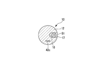
- FIG. 14 is a cross-sectional view taken along line BB in FIG. 13. It is a typical perspective view shown with a partial cross section in order to demonstrate the effect
- FIG. 24 is a cross-sectional view taken along the line CC of FIG. 23.
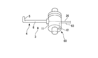
- FIG. 1 is a schematic diagram showing a medical device according to a first embodiment of the present invention.
- FIG. 2 is a schematic view showing a state in which the medical instrument is attached to the endoscope.
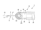
- FIG. 3 is an enlarged schematic view showing the distal end portion of the medical device, and is a plan view of the medical device.
- FIG. 4 is an enlarged schematic view showing the distal end portion of the medical device, and is a side view of the medical device.
- FIG. 5 is a sectional view taken along line AA in FIG.
- FIG. 6 is an enlarged schematic view showing the distal end portion of the medical device, and is a plan view of the medical device.
- the medical instrument 1 includes an insertion portion 2 that can be inserted into the body, and a drive mechanism 30 that is connected to the insertion portion 2.
- the insertion portion 2 has an elongated shape that can be inserted into the forceps channel 101 or the like in an endoscope 100 (see FIG. 2) or other known manipulator.
- the insertion portion 2 includes a treatment portion 3, a joint portion 10, a flexible tube portion 20, a driving force transmission portion 21, and a power feeding cable 26.
- the side of the insertion portion 2 where the treatment portion 3 is provided is referred to as a distal side (distal end), and the side opposite to the side where the treatment portion 3 is provided is a proximal side (proximal end). Called.
- the treatment unit 3 performs treatment on the treatment target site.
- the treatment unit 3 includes an incision electrode 4 that receives a high-frequency current to incise a living tissue.
- the incision electrode 4 has a rod-shaped shaft portion 6 and a hook portion 5 provided on the distal end side of the shaft portion 6.
- the shaft portion 6 and the hook portion 5 are made of conductive metal wires.
- the metal wire to be the cutting electrode 4 has a shape bent at the boundary portion between the shaft portion 6 and the hook portion 5.
- the shaft portion 6 may be provided with an insulating film that covers the outer surface of the metal wire.
- the hook portion 5 of the incision electrode 4 may be, for example, a round shape.
- the incision electrode 4 may not have the hook portion 5.
- the joint portion 10 includes a rotation shaft 11 to which the proximal end of the shaft portion 6 of the incision electrode 4 is fixed, and a support portion 12 that supports the rotation shaft 11.
- the rotation shaft 11 has a substantially cylindrical shape, and the center line O1 of the shaft portion 6 and the center line O2 of the rotation shaft 11 are perpendicular to each other.
- the rotation shaft 11 is connected to the support portion 12 so as to be rotatable with respect to the support portion 12 with the center line O2 as the rotation center.
- the support part 12 includes a connecting part 13 connected to the rotating shaft 11, a fixing part 16 fixed to the flexible tube part 20, and a storage part 18 arranged between the connecting part 13 and the fixing part 16. Is provided.
- the connecting portion 13 supports both ends of the rotation shaft 11 with a predetermined clearance so that the rotation shaft 11 can freely rotate around the center line that is the rotation center.
- the connecting portion 13 includes a first wall portion 14 to which one end of the rotating shaft 11 in the center line direction of the rotating shaft 11 is connected, and the rotating shaft 11 in the center line direction of the rotating shaft 11. And a second wall portion 15 connected at the other end.
- the connecting portion 13 defines the direction of the rotation center of the rotation shaft 11.
- the fixing part 16 is a part for fixing the connecting part 13 to the tip of the flexible tube part 20. Inside the fixed portion 16, the above-described power feeding cable 26 and the first wire 24 and the second wire 25 constituting the driving force transmitting portion 21 are inserted. Further, a part of the outer peripheral surface of the fixed portion 16 has a slit 17 that is long in a linear direction connecting the distal end and the proximal end. The slit 17 formed in the fixed portion 16 is an entrance when the treatment portion 3 is stored in the storage portion 18.
- the storage portion 18 is provided in the support portion 12, and the shape thereof is defined by the inner surface of the connecting portion 13 and the inner surface of the fixing portion 16.
- the storage unit 18 can store at least a part of the incision electrode 4 which is the treatment unit 3 (see FIG. 6).
- the storage unit 18 may be capable of storing the entire incision electrode 4.
- the joint part 10 can support the treatment part 3 and change the direction of the treatment part 3. Further, the treatment section 3 can be stored in the storage section 18 and the treatment section 3 can be taken out from the storage section 18.
- the first wire 24 and the second wire 25 constitute the driving force transmission unit 21.
- the driving force transmission unit 21 includes a disk-shaped first pulley 22 and second pulley 23 centering on the rotation center of the rotation shaft 11, and the first pulley 22 on the tip end side.
- a first wire 24 having a fixed portion
- a second wire 25 having a distal end fixed to the second pulley 23. Both the first pulley 22 and the second pulley 23 are fixed to the rotating shaft 11. For this reason, the first pulley 22 and the second pulley 23 rotate together with the rotating shaft 11.
- first pulley 22 and the second pulley 23 are fixed to the rotating shaft 11
- the first pulley 22 and the second pulley 23 are not provided, but the end portion on the distal end side of the first wire 24 and the second pulley 23 are not provided.
- the end portion on the distal end side of the wire 25 may be directly fixed to the rotating shaft 11.
- the direction in which the first wire 24 is wound around the first pulley 22 and the direction in which the second wire 25 is wound around the second pulley 23 are opposite to each other (see FIG. 3).
- the circumferential length in which the first wire 24 is wound around the first pulley 22 and the circumferential length in which the second wire 25 is wound around the second pulley are the treatment portion 3 when the treatment portion 3 is used.
- a minimum movable range is required so that the treatment section 3 can be positioned in the storage section 18 and the treatment section 3 can be exposed from the storage section 18.
- the first wire 24 is hung on the first pulley 22 and the second wire 25 is hung on the second pulley 23 so as to satisfy at least this movable range.
- first wire 24 and the second wire 25 a wire made of a known material such as stainless steel or resin may be appropriately selected and employed.
- the first wire 24 and the second wire 25 may be made of the same material, or may be made of different materials.
- the proximal end of the first wire 24 and the proximal end of the second wire 25 are drawn into the drive mechanism 30 through the flexible tube portion 20 of the insertion portion 2.
- the proximal end of the first wire 24 and the proximal end of the second wire 25 are connected to the driving force generating unit 32.
- the driving force generation unit 32 generates driving force for moving the first wire 24 and the second wire 25 in the center line direction (longitudinal axis direction of the insertion unit 2).
- the driving force generated by the driving force generation unit 32 is driven to change the direction of the treatment unit 3 through the first wire 24, the second wire 25, the first pulley 22, and the second pulley 23 of the driving force transmission unit 21. It is transmitted to the joint 10 as force.
- the power supply cable 26 is a flexible wire having a conductive core wire through which a high-frequency current flows and an insulating film covering the core wire.
- the distal end of the power supply cable 26 is electrically connected to the metal wire of the cutting electrode 4, and the proximal end of the power supply cable 26 is fixed to a plug 35 described later in the drive mechanism 30.
- a high frequency current can be supplied from the plug 35 to the incision electrode 4 through the power supply cable 26.
- the drive mechanism 30 includes a base 31, a drive force generator 32, and a plug 35.
- the driving force generator 32 includes a first actuator 33 that generates a driving force that pulls the first wire 24, and a second actuator 34 that generates a driving force that pulls the second wire 25.
- Specific configurations of the first actuator 33 and the second actuator 34 are not limited as long as appropriate traction force can be transmitted to the first wire 24 and the second wire 25.
- the first actuator 33 and the second actuator 34 may use a mechanism that pulls the first wire 24 and the second wire 25 by converting the driving force of the motor into a linear movement by a rack and pinion.
- the first actuator 33 and the second actuator 34 have pulleys around which the first wire 24 and the second wire 25 are wound, and a mechanism for rotating these pulleys using a motor is used. Good.
- the plug 35 is made of a conductor that can be connected to a known high-frequency power supply device, and is connected to the proximal end of the power supply cable 26.
- the medical instrument 1 is inserted into the channel 101 in a manipulator such as the endoscope 100 shown in FIG.
- the channel 101 is provided for guiding forceps and other instruments to a treatment target site.
- one of the first wire 24 and the second wire 25 (the second wire 25 in the present embodiment) is connected to the driving force generator so that the treatment section 3 moves into the storage section 18. Tow by 32.
- the second actuator 34 of the driving force generator 32 pulls the second wire 25 toward the proximal end, the driving force of the first actuator 33 is released, and the first wire 24 is moved in the direction of the center line ( It can be freely advanced and retracted in the longitudinal direction of the insertion portion 2.
- the incision electrode 4 which is the treatment part 3 is accommodated in the accommodating part 18 (refer FIG. 6).
- the length of the treatment unit 3 in the linear direction connecting the distal end and the base end as compared with the state in which the treatment unit 3 is out of the storage unit 18. Is short (see FIGS. 3 and 6). For this reason, when the channel 101 is in a curved state, the treatment unit 3 is unlikely to interfere with the inner surface of the channel 101, and the treatment unit 3 is less likely to damage the inner surface of the channel 101.
- the treatment unit 3 In the state where the treatment unit 3 is stored in the storage unit 18, the treatment unit 3 is guided to the vicinity of the treatment target site.
- the treatment unit 3 When a treatment using the treatment unit 3 is performed on the treatment target site with the treatment unit 3 and the joint unit 10 being extended from the distal end of the channel 101, the treatment unit 3 is moved from the inside of the storage unit 18 to the outside.
- the first actuator 24 is used to pull the first wire 24 toward the proximal end, and the driving force of the second actuator 34 is increased. To release.
- the first pulley 22 and the second pulley 23 and the rotation shaft 11 fixed to the first pulley 22 and the second pulley 23 are rotated so that the treatment section 3 comes out of the storage section 18 through the slit 17 of the storage section 18.
- the incision electrode 4 of the treatment section 3 is moved from the storage section 18 into the storage section 18 so as to have a desired orientation and posture suitable for the treatment by rotation about the rotation center O2 of the rotation shaft 11. Move out of 18.
- part can be incised by supplying a high frequency current with respect to the incision electrode 4 which is the treatment part 3 through the electric power feeding cable 26.
- the direction and posture of the incision electrode 4 can be optimized by appropriately pulling the first wire 24 and the second wire 25.
- the treatment part 3 is retracted by pulling the second wire 25 to the proximal end side.
- the medical instrument 1 can be removed from the channel 101 without the treatment section 3 coming into contact with the inner surface of the channel 101.
- the treatment section 3 can be rotated around the rotation center of the rotation shaft 11 and the treatment section 3 can be stored in the joint section 10. Therefore, a mechanism for optimizing the orientation and posture of the treatment unit 3 when performing treatment on the treatment target site using the treatment unit 3, and the treatment unit 3 is moved to store the treatment unit 3 in the storage unit 18. It can also be used as a mechanism for making it happen. Therefore, the medical instrument 1 can be reduced in size compared with the case where the structure specialized for accommodating the treatment part 3 is provided separately.
- the treatment part 3 is accommodated in the inside of the connection part 13 and the fixing
- the treatment tool can be contained within the long range. Thereby, the insertion part 2 of the medical instrument 1 can be easily passed through the channel 101 in a curved state.
- FIG. 7 is a schematic perspective view showing an enlarged distal end portion of the medical device according to the second embodiment of the present invention.
- FIG. 8 is a schematic plan view for explaining a configuration of a part of the switching mechanism provided at the distal end portion of the medical device.
- FIG. 9 is a schematic perspective view showing a partial cross section for explaining the shape of the spring terminal in the switching mechanism provided at the distal end portion of the medical device.
- FIG. 10 is a schematic side view showing the configuration of the columnar terminal in the switching mechanism provided at the distal end portion of the medical device.
- FIG. 11 is a partially enlarged view of FIG.
- FIG. 12 is a schematic perspective view for explaining the operation of the medical device.
- the medical device 1 ⁇ / b> A of the present embodiment has the mechanism for releasing the electrical connection between the incision electrode 4 and the power supply cable 26 when stored, and is the same as that of the first embodiment.
- the configuration is different from that of the medical instrument 1. That is, the medical instrument 1A of the present embodiment further includes the switching mechanism 40 in the joint portion 10.
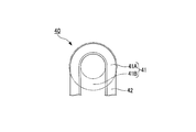
- the switching mechanism 40 is electrically connected to the curved contact portion 41 provided on one of the first wall portion 14 and the second wall portion 15 (the second wall portion 15 in the present embodiment) and the metal wire of the incision electrode 4. And columnar terminals 43 connected to each other.
- the curved contact portion 41 is provided so as to be adjacent to the conduction region 41A, forming a conduction region 41A that forms a part of an arc, a part of an arc having the same radius as the conduction region 41A.
- a spring terminal 42 for passing a high-frequency current to the cutting electrode 4 is arranged in the conduction region 41A.
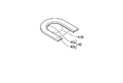
- the spring terminal 42 is an arc-shaped leaf spring having an urging force for pressing the spring terminal 42 against the columnar terminal 43 and having substantially the same radius as the arc of the conduction region 41A.
- a slope 42 a for reducing a step between the insulating region 41 ⁇ / b> B and the spring terminal 42 is formed at a boundary portion between the conductive region 41 ⁇ / b> A and the insulating region 41 ⁇ / b> B in the spring terminal 42.
- the surface directed to the columnar terminal 43 is the flat portion 42b.
- the flat part 42b can contact the protruding end of the columnar terminal 43.
- the lead portion 42 c is provided on the proximal end side of the spring terminal 42, and electrically connects the spring terminal 42 and the power supply cable 26.
- the insulated region 41B is a region insulated from the power supply cable 26.
- the columnar terminal 43 is not supplied with a high-frequency current from the power supply cable 26 (see FIG. 12).
- the columnar terminal 43 is not physically in contact with the spring terminal 42 in the insulating region, but the insulating region 41B may have an insulator or be insulated from the power supply cable 26. If it is, it may have a conductor in part.
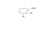
- the columnar terminal 43 is a columnar conductor that is integrated with the metal wire of the cutting electrode 4 or fixed to the metal wire. It protrudes from the outer surface.
- the protruding end 43a of the columnar terminal 43 can contact the flat portion 42b of the spring terminal 42 and the insulating region 41B. That is, the protruding end 43 a of the columnar terminal 43 rotates around the rotation center together with the rotation shaft 11 when the rotation shaft 11 rotates around the rotation center of the rotation shaft 11.
- the turning radius of the projecting end portion 43 a of the columnar terminal 43 is substantially equal to the radius of the curved contact portion 41.
- a step is formed between the insulating region 41B and the spring terminal 42.
- a tapered portion 43 b is formed on the peripheral portion of the protruding end portion 43 a of the columnar terminal 43 so as to easily get over the step between the insulating region 41 ⁇ / b> B and the spring terminal 42.
- the inner region of the tapered portion 43 b is a flat portion 43 c that can come into surface contact with the flat portion 42 b of the spring terminal 42.
- the operation of the medical instrument 1A of the present embodiment will be described focusing on the operation of the switching mechanism 40.
- the switching mechanism 40 when the cutting electrode 4 is located in the storage portion 18, the switching mechanism 40 is configured such that the protruding end portion 43 a of the columnar terminal 43 is located in the insulating region 41 ⁇ / b> B. 4 and the power supply are cut off.
- the switching mechanism 40 when the cutting electrode 4 is located outside the storage portion 18, the switching mechanism 40 has the protruding end portion 43a of the columnar terminal 43 in contact with the flat portion 42b of the spring contact in the conduction region 41A.
- the power supply cable 26 and the cutting electrode 4 are made conductive.
- the medical instrument 1A of the present embodiment when the incision electrode 4 that is the treatment section 3 is stored in the storage section 18, no high-frequency current is passed through the incision electrode 4. For this reason, even when an operation for applying a high-frequency current by mistake when storing the incision electrode 4 does not flow, the high-frequency current does not flow through the incision electrode 4 and is less likely to break than the medical instrument 1 of the first embodiment. High safety.
- FIG. 13 is a typical perspective view which shows the medical device of 3rd Embodiment of this invention in a partial cross section.
- FIG. 14 is a cross-sectional view taken along line BB in FIG.
- FIG. 15 is a schematic perspective view showing a partial cross section for explaining the operation of the medical device.
- FIG. 16 is a schematic perspective view showing a configuration of a modified example of the medical device.
- the medical instrument 1B of the present embodiment is different in configuration from the medical instrument 1 of the first embodiment described above in that it has a mechanism for cleaning the incision electrode 4 during the storing operation. Yes. That is, the medical instrument 1B of the present embodiment further includes a cleaning mechanism 50 in the joint portion 10. As shown in FIG. 13, the cleaning mechanism 50 includes a flexible water supply tube 51 through which cleaning water flows and a position changing mechanism 52 that changes the position of the discharge port 51 a of the water supply tube 51.
- the water supply tube 51 is a tube arranged along the longitudinal axis of the insertion portion 2.
- the flexible tube portion 20 passes through the gap of the slit 17. It is arranged inside and extends to the drive mechanism 30.
- the opening at the tip of the water supply tube 51 is a discharge port 51a for the cleaning water, and the opening at the base end of the water supply tube 51 is a supply port for the cleaning water.
- the water supply tube 51 can move forward and backward in the longitudinal direction of the insertion portion 2 with respect to the insertion portion 2. The forward / backward movement of the water supply tube 51 along the longitudinal direction of the insertion portion 2 is controlled by the position changing mechanism 52.
- the position changing mechanism 52 is arranged in the drive mechanism 30 and is connected to a portion of the water supply tube 51 located in the drive mechanism 30.
- the position changing mechanism 52 includes an actuator (not shown) that moves the water supply tube 51 forward and backward in the center line direction (longitudinal axis direction of the insertion portion 2).
- the discharge port 51 a is located at the distal end of the joint portion 10.
- the discharge port 51 a is located at the proximal end of the slit 17.
- the position changing mechanism 52 may not be provided in the medical instrument 1B. In this case, the position of the discharge port 51 a is fixed in a state where the discharge port 51 a of the water supply tube 51 is at the proximal end of the slit 17.
- the cleaning mechanism 50 can be used as a water supply port for supplying cleaning water to the treatment target site when the treatment unit 3 is located outside the storage unit 18 (see FIG. 13). At this time, the position of the discharge port 51a of the water supply tube 51 is moved to the distal end side of the slit 17 or from the slit 17 further to the distal end side by the position changing mechanism 52, so that the discharge port is located at a position close to the treatment target site. 51a can be arranged.
- the cleaning mechanism 50 also has a function of cleaning the treatment section 3 by supplying cleaning water to the treatment section 3 in a state where the treatment section 3 is located outside the storage section 18.
- the position changing mechanism 52 moves the position of the discharge port 51 a at the distal end of the water supply tube 51 to the proximal end of the slit 17. Thereby, the slit 17 is opened, and an inlet for introducing the treatment section 3 into the storage section 18 is generated.
- the position changing mechanism 52 is not provided, the slit 17 is always open, and the treatment section 3 can pass through the slit 17.
- washing water is discharged from the discharge port 51 a at the tip of the water supply tube 51.
- the supply of cleaning water may start after the treatment section 3 has moved into the storage section 18. In this case, when the treatment unit 3 is stored in the storage unit 18, the foreign matter is removed in the storage unit 18.
- the hook portion 5 at the tip of the treatment portion 3 rotates so as to approach the discharge port 51a, so that there is a high degree of certainty that the cleaning water discharged from the discharge port 51a reaches the hook portion 5.
- the distal end of the treatment unit 3 is a portion that is frequently contacted with the treatment target site when a treatment is performed on the treatment target site, and is likely to be attached with foreign matter.
- foreign substances such as burned tissue tend to adhere to the hook portion 5.
- the distal end of the treatment unit 3 can be efficiently cleaned.
- FIG. 16 is a schematic perspective view showing a configuration of a modified example of the medical device.
- the present modified example is different from the above-described medical instrument 1 ⁇ / b> B in that it has means for scraping off the foreign matter adhering to the distal end of the treatment section 3. That is, the medical instrument 1C of the present modification includes a brush 50A (cleaning mechanism 50A) attached to the slit 17 of the support unit 12 instead of the cleaning mechanism 50.
- a brush 50A cleaning mechanism 50A
- the brush 50 ⁇ / b> A has such a hardness that it can scrape off a piece of living tissue adhered to the hook portion 5 of the incision electrode 4, for example.
- the cleaning mechanism 50A may have a spatula in the slit 17 that is flexible with a resin such as rubber and hard enough to scrape off foreign matter, instead of the brush 50A.
- FIG. 17 is a schematic overall view of a medical system according to a fourth embodiment of the present invention.
- FIG. 18 is a schematic diagram showing a partially broken front end portion of the medical device of the embodiment provided in the medical system.
- FIG. 19 is a schematic perspective view showing a configuration of a switch unit provided in the joint part by enlarging a part of the joint part of the medical device.
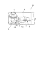
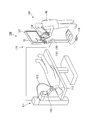
- the medical system 150 includes a manipulator device 110 for an operator who performs an operation on a patient to perform an operation on the patient, and a medical instrument 1D attached to the manipulator device 110.
- the manipulator device 110 controls the slave manipulator 111 to which the medical instrument 1D is attached, the master manipulator 115 that is electrically connected to the slave manipulator 111 and issues an operation command to the slave manipulator 111, and the entire medical system 150. And a control unit 120.
- the slave manipulator 111 has at least a slave arm 112 to which the above-described medical instrument 1D is attached, an actuator (not shown) for operating the slave arm 112, and a sensor (not shown) for detecting the position of the slave arm 112. is doing.
- the slave manipulator 111 receives an operation command from the master manipulator 115, and operates the slave arm 112 and the medical instrument 1D according to the operation command. That is, in this embodiment, the slave manipulator 111 is connected to at least the driving force generation unit 32 of the medical instrument 1D, and can operate the driving force generation unit 32 in response to an operation command from the master manipulator 115. .
- the slave arm 112 of the present embodiment has a soft long axis member 113 inserted into the body, and has a channel 101A for passing the insertion part 2 of the medical instrument 1D in the long axis member 113.
- An imaging mechanism (not shown) for observing the treatment target site is provided at the distal end of the long axis member 113 of the slave arm 112, and this imaging mechanism acquires an image of the treatment target site.
- the master manipulator 115 displays an image acquired by the imaging mechanism provided on the long arm member 113 of the master arm 116 that operates the medical instrument 1D and the slave arm 112 when the operator Op holds and moves it. And a display unit 117. Furthermore, the master manipulator 115 according to the present embodiment stores the treatment unit 3 in the medical instrument 1D in the storage unit 18 and stores a control for generating a trigger signal for feeding the treatment unit 3 out of the storage unit 18 to the control unit 120. A switch 118 is provided. In the master manipulator 115, when the master arm 116 is operated, an operation command is issued to the control unit 120.
- the control unit 120 outputs a signal for operating the slave manipulator 111 to the slave manipulator 111 based on the operation command and the trigger signal issued from the master manipulator 115.
- the control unit 120 outputs a signal for operating the driving force generation unit 32 of the medical instrument 1D.
- the control unit 120 includes a determination unit 121 that determines a state in which the treatment unit 3 is in the storage unit 18 and a state in which the treatment unit 3 is outside the storage unit 18.
- the medical instrument 1D is different from the medical instrument 1 described in the first embodiment in that the switch part 60 is provided in the joint part 10.
- the state where the treatment unit 3 is inside the storage unit 18 and the state where the treatment unit 3 is outside the storage unit 18 can be distinguished from each other by the conduction state of the switch unit 60.
- the driving force generation unit 32 of the medical instrument 1D is connected to the control unit 120 of the manipulator device 110.
- the driving force generator 32 of the medical instrument 1D responds to the operation command based on the operation input from the master arm 116 and the trigger signal issued from the storage state control switch 118 of the master manipulator 115.
- the wire 24 and the second wire 25 are pulled.
- the switch unit 60 includes a first contact 61 fixed to the rotating shaft 11 of the joint unit 10 and a contact state and a separated state fixed to the support unit 12 with respect to the first contact 61.
- a second contact 62 having two states, a first wiring 63 that electrically connects the first contact 61 and the determination unit 121, and a second that electrically connects the second contact 62 and the determination unit 121.
- Wiring 64
- the first contact 61 is arranged on a part of a circle centering on the rotation center of the rotation shaft 11 on one end face in the rotation center direction of the rotation shaft 11. Yes.
- the second contact 62 is on the first wall portion 14 and the second wall portion 15 of the support portion 12 closer to the first contact 61 (in this embodiment, the second wall portion 15). It is arranged.
- the second contact 62 has an arc shape along a part of a circle having a radius substantially equal to the circle centered on the rotation center of the rotation shaft 11.
- the arc shape of the second contact 62 is a C shape having a cut 62a at least partially.
- the cut line 62 a in the arc shape of the second contact 62 has such a width that the first contact 61 can enter without contacting the second contact 62.
- the cut 62 a enters the cut 62 a in a state in which the treatment portion 3 is arranged in the storage portion 18, and the first contact 61 and the second contact 61 a. 62 is in a non-contact state.
- the treatment unit 3 is inserted into and removed from the storage unit 18 based on the trigger signal when the storage state control switch 118 of the master manipulator 115 is pressed by the operator.
- the determination unit 121 detects whether or not the first contact 61 and the second contact 62 of the switch unit 60 are electrically connected, whereby the first contact 61 and the second contact 62 are electrically connected (that is, the treatment unit). 3 is outside the storage unit 18 (see FIG. 18), and the first contact 61 and the second contact 62 are not conducting (that is, the treatment unit 3 is in the storage unit 18, see FIG. 20). ) And discriminate.
- the determination unit 121 When the first contact 61 and the second contact 62 are conductive, the determination unit 121 returns to the control unit 120 that the treatment unit 3 has gone out of the storage unit 18 and treatment for the treatment target site is possible. . On the other hand, when the first contact 61 and the second contact 62 are not conductive, the determination unit 121 returns to the control unit 120 that the treatment unit 3 is stored in the storage unit 18 and treatment is impossible. .
- the determination unit 121 informs the control unit 120 that the treatment unit 3 is stored in the storage unit 18 and the medical instrument 1D can be replaced. You may return it.
- the control unit 120 causes the display unit 117 to display a status indicating that the operation input using the master arm 116 of the master manipulator 115 is possible based on the determination result in the determination unit 121 if the treatment is possible. Furthermore, the control unit 120 transmits the operation of the master arm 116 of the master manipulator 115 to the slave manipulator 111 as an operation command for the slave manipulator 111.
- the display unit 117 displays that the operation input using the master arm 116 of the master manipulator 115 is impossible, and the operation of the master arm 116 of the master manipulator 115 is performed.
- the operation command based on is invalidated.
- the control unit 120 displays a status indicating that the medical instrument 1D can be replaced on the display unit 117, and based on the operation of the master arm 116 of the master manipulator 115. The operation command is invalidated.
- An operator of the medical system 150 manually performs the medical instrument 1D, which is the same as the medical instrument 1D of the present embodiment, but has a different configuration of the treatment unit 3, for example, or a spare medical instrument of the present embodiment. It can be exchanged for the instrument 1D.
- the medical system 150 can switch between a treatment mode in which treatment using the treatment unit 3 is possible and a device exchange mode in which the medical device 1 can be exchanged.
- the medical instrument 1D newly inserted into the channel 101A of the long shaft member 113 is in a state where the treatment section 3 is stored in the storage section 18.
- the treatment part 3 of this medical instrument 1D is drawn out through the slit 17 from the storage part 18, and a treatment is possible.
- the determination unit 121 determines whether or not the treatment unit 3 is stored in the storage unit 18 in the control unit 120, and thus can be obtained by imaging the treatment target region. It is possible to reliably grasp that the treatment unit 3 is stored in the storage unit 18 without depending on the image. Further, the treatment unit 3 can be taken in and out of the storage unit 18 by using the master manipulator 115.
- FIG. 21 is a schematic diagram showing a configuration of a modified example of the medical device.
- FIG. 22 is an explanatory diagram for explaining the operation of the modified example.
- FIG. 23 is an explanatory diagram for explaining the operation of the modified example.
- a switch unit 60A having a configuration different from that of the above-described switch unit 60 is provided for the medical instrument 1A described in the second embodiment.
- a switch unit 60 ⁇ / b> A for causing the determination unit 121 to determine the storage state of the treatment unit 3 with respect to the storage unit 18 is provided in a part of the switching mechanism 40 described in the second embodiment.
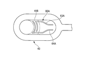
- the switch section 60A has a first wiring 63A and a second wiring 64A, the tips of which are arranged in the insulating region 41B.
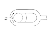
- the leading end of the first wiring 63A and the leading end of the second wiring 64A are brought into conduction when the projecting end portions 43a of the columnar terminals 43 are in contact with each other (see FIGS. 23 and 24).
- the first wiring 63 ⁇ / b> A and the second wiring 64 ⁇ / b> A are in an insulated state, and a high-frequency current can be passed through the columnar terminal 43 through the spring terminal 42. is there.
- the base end of the first wiring 63A and the base end of the second wiring 64A are connected to the determination unit 121. Therefore, the storage state of the treatment section 3 can be determined by determining whether or not the first wiring 63A and the second wiring 64A are in a conductive state by the columnar terminal 43. Also in this modification, the same effects as those of the present embodiment are obtained.
- the determination unit 121 determines whether or not the treatment unit 3 is in the storage unit 18 by referring to the pulling amount of the first wire 24 by the first actuator 33. Even with such a configuration, the same effects as in the present embodiment can be obtained.
- the control unit 120 may perform control so as to prohibit energization of the high-frequency current to the incision electrode 4 when the treatment unit 3 is stored in the storage unit 18. That is, in the present modification, the control unit 120 performs energization control of the high-frequency current to the incision electrode 4. In the case of this modification, it is not necessary to provide the switching mechanism 40 in the energized state of the high-frequency current as described in the second embodiment.
- control unit 120 may perform control to relax the long axis member 113 of the slave arm 112 when the treatment unit 3 is stored in the storage unit 18.
- the long shaft member 113 of the slave arm 112 can be freely bent by operating the master arm 116 of the master manipulator 115.
- the bending operation of the long-axis member 113 of the slave arm 112 includes the above-described relaxation control by the control unit 120. Therefore, when the treatment unit 3 is stored in the storage unit 18, the medical instrument 1D is replaced.
- the long axis member 113 of the slave arm 112 can be relaxed for the purpose of facilitating.
- the control unit 120 can also facilitate replacement of the medical instrument 1D with the other joints in a relaxed state.
- the storage unit has a mechanism for optimizing the orientation and posture of the treatment unit when performing a treatment on the treatment target site using the treatment unit; It also serves as a mechanism for moving the treatment section in order to store the treatment section in the storage section.
Landscapes
- Health & Medical Sciences (AREA)
- Surgery (AREA)
- Engineering & Computer Science (AREA)
- Life Sciences & Earth Sciences (AREA)
- Medical Informatics (AREA)
- General Health & Medical Sciences (AREA)
- Biomedical Technology (AREA)
- Heart & Thoracic Surgery (AREA)
- Nuclear Medicine, Radiotherapy & Molecular Imaging (AREA)
- Molecular Biology (AREA)
- Animal Behavior & Ethology (AREA)
- Veterinary Medicine (AREA)
- Public Health (AREA)
- Cardiology (AREA)
- Physics & Mathematics (AREA)
- Plasma & Fusion (AREA)
- Otolaryngology (AREA)
- Robotics (AREA)
- Surgical Instruments (AREA)
Abstract
Description
本願は、2013年3月28日に、米国に仮出願された米国特許出願第61/806,114号に基づき優先権を主張し、その内容をここに援用する。
例えば、特許文献1には、内視鏡のチャンネルの内面を保護する目的で、処置部を収納する収納部を設けた医療器具が記載されている。
本発明の第1の態様の医療器具は、体内に挿入可能な挿入部と、前記挿入部に連結された駆動機構と、を備え、前記挿入部は、処置対象部位に対して処置を行う処置部と、前記処置部を支持し前記処置部の向きを変更可能な関節部と、前記関節部に設けられ前記処置部を内部に収納可能な収納部と、前記関節部に接続され前記処置部の向きを変更するための駆動力を前記関節部に伝達する駆動力伝達部と、を有し、前記駆動機構は、前記駆動力伝達部に接続され前記駆動力を発生させる駆動力発生部を有し、前記駆動力発生部が前記駆動力伝達部を介して前記関節部に伝達する前記駆動力によって前記処置部が前記収納部に対して出入りする。
本発明の医療器具(medical device)の実施形態について、図1から図6を参照して説明する。
図1は、本発明の第1実施形態の医療器具を示す模式図である。図2は、同医療器具が内視鏡に取り付けられた状態を示す模式図である。図3は、同医療器具の先端部分を拡大して示す模式図であり、同医療器具の平面図である。図4は、同医療器具の先端部分を拡大して示す模式図であり、同医療器具の側面図である。図5は、図4のA-A線に沿った断面図である。図6は、同医療器具の先端部分を拡大して示す模式図であり、同医療器具の平面図である。
図1に示すように、医療器具1は、体内に挿入可能な挿入部2と、挿入部2に連結された駆動機構30とを備える。
切開電極4は、棒状の軸部6と、軸部6の先端側に設けられたフック部5とを有する。軸部6及びフック部5は導電性を有する金属線からなる。切開電極4となる金属線は、軸部6とフック部5との境界部分において折り曲げられた形状を有する。軸部6には、金属線の外面を被覆する絶縁皮膜が設けられていてもよい。切開電極4のフック部5は、たとえば丸型などであってもよい。切開電極4は、フック部5を有していなくてもよい。
支持部12は、回動軸11に連結された連結部13と、可撓管部20に固定された固定部16と、連結部13と固定部16との間に配された収納部18とを備える。
医療器具1は、例えば図2に示す内視鏡100等のマニピュレータにおいて、チャンネル101内に挿通される。チャンネル101は、鉗子及びその他の器具を処置対象部位まで案内するために設けられている。チャンネル101への挿入時には、処置部3が収納部18内へと移動するように第一ワイヤ24と第二ワイヤ25とのうちの一方(本実施形態では第二ワイヤ25)を駆動力発生部32により牽引する。本実施形態では、駆動力発生部32の第二アクチュエータ34が第二ワイヤ25を基端側へと牽引し、第一アクチュエータ33の駆動力が解除されて第一ワイヤ24をその中心線方向(挿入部2の長手軸方向)へ自在に進退させる。これにより、処置部3である切開電極4は収納部18内に収納される(図6参照)。処置部3が収納部18内に収納されている状態では、処置部3が収納部18の外に出ている状態と比較して、先端と基端とを結ぶ直線方向における処置部3の長さが短い(図3及び図6参照)。このため、チャンネル101が湾曲した状態である場合に、処置部3がチャンネル101の内面に干渉しにくく、また処置部3がチャンネル101の内面を傷つけにくい。
次に、本発明の医療器具1の他の実施形態について、図7から図12を参照しながら説明する。本実施形態以下では、既に説明された実施形態に記載された構成と同様の構成要素には同一の符号が付されており、重複する説明は省略されている。
図7は、本発明の第2実施形態の医療器具の先端部分を拡大して示す模式的な斜視図である。図8は、同医療器具の先端部分に設けられたスイッチング機構の一部の構成を説明するための模式的な平面図である。図9は、同医療器具の先端部分に設けられたスイッチング機構におけるバネ端子の形状を説明するために一部断面で示す模式的な斜視図である。図10は、同医療器具の先端部分に設けられたスイッチング機構における柱状端子の構成を示す模式的な側面図である。図11は、図10の一部拡大図である。図12は、同医療器具の作用を説明するための模式的な斜視図である。
導通領域41Aには、切開電極4に対する高周波電流を通電させるためのバネ端子42が配置されている。バネ端子42は、バネ端子42自身を柱状端子43に押し付けるための付勢力を有し、導通領域41Aの円弧と略同一半径を有する円弧状の板バネである。
図12に示すように、スイッチング機構40は、切開電極4が収納部18内に位置しているときには、柱状端子43の突端部43aが絶縁領域41Bに位置することにより、給電ケーブル26と切開電極4と通電を遮断している。また、図7に示すように、スイッチング機構40は、切開電極4が収納部18外に位置しているときには、柱状端子43の突端部43aが導通領域41Aにおいてバネ接点の平坦部42bに接することにより、給電ケーブル26と切開電極4とを導通させる。
次に、本発明の医療器具1のさらに他の実施形態について、図13から図15を参照しながら説明する。
図13は、本発明の第3実施形態の医療器具を一部断面で示す模式的な斜視図である。図14は、図13のB-B線に沿った断面図である。図15は、同医療器具の作用を説明するために一部断面で示す模式的な斜視図である。図16は、同医療器具の変形例の構成を示す模式的な斜視図である。
図13に示すように、洗浄機構50は、洗浄水が流れる柔軟な送水チューブ51と、送水チューブ51の吐出口51aの位置を変更する位置変更機構52を有する。
処置部3が収納部18内へと移動してから洗浄水の供給が始まってもよい。この場合、処置部3は、収納部18内に収納されたときに、収納部18内において異物が除去される。
次に、本実施形態の変形例について図16を参照しながら説明する。
図16は、同医療器具の変形例の構成を示す模式的な斜視図である。
次に、本発明の医療システムの実施形態について図17から図20を参照しながら説明する。本実施形態において、本実施形態の医療システムに設けられた医療器具の構成および作用について、特に明記した事項以外は、第1実施形態の医療器具1と同様である。
図17は、本発明の第4実施形態の医療システムの模式的な全体図である。図18は、同医療システムに設けられた同実施形態の医療器具の先端部分を一部破断して示す模式図である。図19は、同医療器具の関節部の一部を拡大して同関節部に設けられたスイッチ部の構成を示す模式的な斜視図である。図20は、同医療器具の作用を説明するための模式図である。図24は、図23のC-C線に沿った断面図である。
スレーブマニピュレータ111は、マスタマニピュレータ115から操作指令を受け、操作指令に従って、スレーブアーム112、及び医療器具1Dを動作させる。すなわち、本実施形態では、スレーブマニピュレータ111は、少なくとも医療器具1Dの駆動力発生部32に接続されており、マスタマニピュレータ115からの操作指令に対応して駆動力発生部32を動作させることができる。
マスタマニピュレータ115において、マスタアーム116が動作されることにより、操作指令が制御部120に発せられる。
制御部120は、医療器具1Dの駆動力発生部32を動作させるための信号を出力する。また、制御部120は、処置部3が収納部18内にある状態と処置部3が収納部18外にある状態とを判定する判定部121を有する。
また、第二接点62は、回動軸11の回動中心を中心とする上記円と略等しい半径の円の一部に沿った円弧形状を有している。第二接点62の円弧形状は少なくとも一部に切れ目62aを有するC字形状である。
本実施形態では、収納部18に対する処置部3の出し入れは、マスタマニピュレータ115の収納状態制御スイッチ118が操作者に押されることにより、トリガー信号に基づいて開始される。
医療システム150の操作者は、たとえば手作業によって、医療器具1Dを、本実施形態の医療器具1Dと同様であるが例えば処置部3の構成が異なる医療器具1や、予備の本実施形態の医療器具1Dへと交換することができる。
また、収納部18に対する処置部3の出し入れがマスタマニピュレータ115の使用により行なうことができる。
次に、本実施形態の変形例について図21から図24を参照しながら説明する。
図21は、同医療器具の変形例の構成を示す模式図である。図22は、同変形例の作用を説明するための説明図である。図23は、同変形例の作用を説明するための説明図である。
本変形例においても、本実施形態と同様の効果を奏する。
次に、本実施形態の他の変形例について説明する。
本変形例では、判定部121は、第一アクチュエータ33による第一ワイヤ24の牽引量を参照することによって、処置部3が収納部18内にあるか否かを判定する。
このような構成であっても本実施形態と同様の効果を奏する。
次に、本実施形態のさらに他の変形例について説明する。
本変形例では、制御部120によって医療器具1Dの他の部分を制御するいくつかの例を示す。
2 挿入部
3 処置部
10 関節部
18 収納部
21 駆動力伝達部
30 駆動機構
32 駆動力発生部
Claims (4)
- 体内に挿入可能な挿入部と、
前記挿入部に連結された駆動機構と、
を備え、
前記挿入部は、
処置対象部位に対して処置を行う処置部と、
前記処置部を支持し前記処置部の向きを変更可能な関節部と、
前記関節部に設けられ前記処置部を内部に収納可能な収納部と、
前記関節部に接続され前記処置部の向きを変更するための駆動力を前記関節部に伝達する駆動力伝達部と、
を有し、
前記駆動機構は、前記駆動力伝達部に接続され前記駆動力を発生させる駆動力発生部を有し、
前記駆動力発生部が前記駆動力伝達部を介して前記関節部に伝達する前記駆動力によって前記処置部が前記収納部に対して出入りする
医療器具。 - 前記処置部は、高周波電流の供給を受けて生体組織を切開する切開電極を有し、
前記関節部は、前記切開電極に対する前記高周波電流の通電状態を切り替えるスイッチング機構を有し、
前記挿入部は、前記スイッチング機構に接続され前記高周波電流が通電される給電ケーブルを有し、
前記駆動機構は、前記給電ケーブルに接続され高周波電源装置に接続可能なプラグを有し、
前記スイッチング機構は、前記切開電極が前記収納部内に位置しているときには前記給電ケーブルと前記切開電極と通電を遮断し、前記切開電極が前記収納部外に位置しているときには前記給電ケーブルと前記切開電極とを導通させる
請求項1に記載の医療器具。 - 前記処置部に付着している異物を前記処置部が前記収納部外から前記収納部内へと移動する過程もしくは前記収納部内において除去する洗浄機構をさらに備える
請求項1または請求項2に記載の医療器具。 - 請求項1から請求項3のいずれか1項に記載の医療器具と、
操作者からの操作入力を受け付けるマスタマニピュレータと、
前記マスタマニピュレータに接続された制御部と、
前記制御部に接続されているとともに前記駆動機構に接続されたスレーブマニピュレータと、
前記制御部に設けられ前記処置部が前記収納部内にある状態と前記処置部が収納部外にある状態とを判定する判定部と、
を備える
医療システム。
Priority Applications (4)
| Application Number | Priority Date | Filing Date | Title |
|---|---|---|---|
| JP2015508119A JP5989230B2 (ja) | 2013-03-28 | 2014-01-22 | 医療器具及び医療システム |
| EP14772887.7A EP2979656B1 (en) | 2013-03-28 | 2014-01-22 | Medical instrument and medical system |
| CN201480017628.0A CN105050522B (zh) | 2013-03-28 | 2014-01-22 | 医疗器具和医疗系统 |
| US14/855,708 US10390878B2 (en) | 2013-03-28 | 2015-09-16 | Medical device and medical system |
Applications Claiming Priority (2)
| Application Number | Priority Date | Filing Date | Title |
|---|---|---|---|
| US201361806114P | 2013-03-28 | 2013-03-28 | |
| US61/806,114 | 2013-03-28 |
Related Child Applications (1)
| Application Number | Title | Priority Date | Filing Date |
|---|---|---|---|
| US14/855,708 Continuation US10390878B2 (en) | 2013-03-28 | 2015-09-16 | Medical device and medical system |
Publications (1)
| Publication Number | Publication Date |
|---|---|
| WO2014156244A1 true WO2014156244A1 (ja) | 2014-10-02 |
Family
ID=51623247
Family Applications (1)
| Application Number | Title | Priority Date | Filing Date |
|---|---|---|---|
| PCT/JP2014/051230 Ceased WO2014156244A1 (ja) | 2013-03-28 | 2014-01-22 | 医療器具及び医療システム |
Country Status (5)
| Country | Link |
|---|---|
| US (1) | US10390878B2 (ja) |
| EP (1) | EP2979656B1 (ja) |
| JP (1) | JP5989230B2 (ja) |
| CN (1) | CN105050522B (ja) |
| WO (1) | WO2014156244A1 (ja) |
Cited By (1)
| Publication number | Priority date | Publication date | Assignee | Title |
|---|---|---|---|---|
| CN114010306A (zh) * | 2021-12-06 | 2022-02-08 | 郑州大学第一附属医院 | 一种可弯折电钩 |
Families Citing this family (2)
| Publication number | Priority date | Publication date | Assignee | Title |
|---|---|---|---|---|
| CN108742831B (zh) * | 2018-06-12 | 2024-05-17 | 徐州矿务集团总医院 | 内镜下血块清理止血器 |
| US20200405381A1 (en) * | 2019-06-27 | 2020-12-31 | Covidien Lp | Surface ablation device, system and method |
Citations (6)
| Publication number | Priority date | Publication date | Assignee | Title |
|---|---|---|---|---|
| US2541246A (en) * | 1948-07-31 | 1951-02-13 | American Cystoscope Makers Inc | Surgical instrument |
| US5443475A (en) * | 1990-11-09 | 1995-08-22 | Arthrotek, Inc. | Surgical instrument |
| US5797923A (en) * | 1997-05-12 | 1998-08-25 | Aiyar; Harish | Electrode delivery instrument |
| JP2008264253A (ja) | 2007-04-20 | 2008-11-06 | Olympus Medical Systems Corp | 医療用処置具及び内視鏡処置システム |
| US20100168787A1 (en) * | 2008-12-31 | 2010-07-01 | Wilson-Cook Medical Inc. | Medical device with pivotable jaws |
| US20110238053A1 (en) * | 2010-03-25 | 2011-09-29 | Vivant Medical, Inc. | Microwave Surface Coagulator with Retractable Blade |
Family Cites Families (9)
| Publication number | Priority date | Publication date | Assignee | Title |
|---|---|---|---|---|
| JPH11169381A (ja) | 1997-12-15 | 1999-06-29 | Olympus Optical Co Ltd | 高周波処置具 |
| JPH11332880A (ja) * | 1998-05-22 | 1999-12-07 | Olympus Optical Co Ltd | 穿刺治療装置 |
| DE10327237A1 (de) * | 2003-06-17 | 2005-01-13 | Trumpf Medizin Systeme Gmbh + Co. Kg | Elektrochirurgisches Instrument für ein Endoskop |
| JP4895509B2 (ja) * | 2005-02-09 | 2012-03-14 | Hoya株式会社 | 内視鏡用処置具 |
| US8308725B2 (en) * | 2007-03-20 | 2012-11-13 | Minos Medical | Reverse sealing and dissection instrument |
| CN100579479C (zh) * | 2008-07-03 | 2010-01-13 | 哈尔滨工程大学 | 内镜操作手术机器人穿刺孔定位装置 |
| JP5800616B2 (ja) * | 2011-07-15 | 2015-10-28 | オリンパス株式会社 | マニピュレータシステム |
| CN202682047U (zh) * | 2012-07-06 | 2013-01-23 | 荣佳(惠州)医疗器械制造有限公司 | 一次性带双层防高频高压防水结构高频手术电极 |
| CN105101899B (zh) | 2013-03-28 | 2017-07-14 | 奥林巴斯株式会社 | 医疗器具和医疗系统 |
-
2014
- 2014-01-22 JP JP2015508119A patent/JP5989230B2/ja active Active
- 2014-01-22 WO PCT/JP2014/051230 patent/WO2014156244A1/ja not_active Ceased
- 2014-01-22 EP EP14772887.7A patent/EP2979656B1/en active Active
- 2014-01-22 CN CN201480017628.0A patent/CN105050522B/zh active Active
-
2015
- 2015-09-16 US US14/855,708 patent/US10390878B2/en active Active
Patent Citations (6)
| Publication number | Priority date | Publication date | Assignee | Title |
|---|---|---|---|---|
| US2541246A (en) * | 1948-07-31 | 1951-02-13 | American Cystoscope Makers Inc | Surgical instrument |
| US5443475A (en) * | 1990-11-09 | 1995-08-22 | Arthrotek, Inc. | Surgical instrument |
| US5797923A (en) * | 1997-05-12 | 1998-08-25 | Aiyar; Harish | Electrode delivery instrument |
| JP2008264253A (ja) | 2007-04-20 | 2008-11-06 | Olympus Medical Systems Corp | 医療用処置具及び内視鏡処置システム |
| US20100168787A1 (en) * | 2008-12-31 | 2010-07-01 | Wilson-Cook Medical Inc. | Medical device with pivotable jaws |
| US20110238053A1 (en) * | 2010-03-25 | 2011-09-29 | Vivant Medical, Inc. | Microwave Surface Coagulator with Retractable Blade |
Cited By (2)
| Publication number | Priority date | Publication date | Assignee | Title |
|---|---|---|---|---|
| CN114010306A (zh) * | 2021-12-06 | 2022-02-08 | 郑州大学第一附属医院 | 一种可弯折电钩 |
| CN114010306B (zh) * | 2021-12-06 | 2023-06-23 | 郑州大学第一附属医院 | 一种可弯折电钩 |
Also Published As
| Publication number | Publication date |
|---|---|
| US10390878B2 (en) | 2019-08-27 |
| CN105050522B (zh) | 2017-10-20 |
| JP5989230B2 (ja) | 2016-09-07 |
| CN105050522A (zh) | 2015-11-11 |
| EP2979656B1 (en) | 2019-04-24 |
| JPWO2014156244A1 (ja) | 2017-02-16 |
| US20160000503A1 (en) | 2016-01-07 |
| EP2979656A4 (en) | 2016-12-07 |
| EP2979656A1 (en) | 2016-02-03 |
Similar Documents
| Publication | Publication Date | Title |
|---|---|---|
| CN105101899B (zh) | 医疗器具和医疗系统 | |
| JP4729592B2 (ja) | 電気−機械式駆動装置と共に使用される平行な拡張あご装置 | |
| EP2116175B1 (en) | Medical system | |
| JP5350645B2 (ja) | 医療システム及び内視鏡システム | |
| CN104994804A (zh) | 手术工具保持装置、内窥镜和医疗系统 | |
| JP6749545B2 (ja) | 細径内視鏡手術器具 | |
| WO2015125797A1 (ja) | 手術用マニピュレータ操作装置および手術用マニピュレータシステム | |
| JP4282554B2 (ja) | 内視鏡用処置具システム | |
| CN107205788A (zh) | 医疗用机械手系统 | |
| JP5290658B2 (ja) | 内視鏡用処置具 | |
| JP5989230B2 (ja) | 医療器具及び医療システム | |
| EP2762054A1 (en) | Treatment device and endoscopic treatment system | |
| JP2019103804A (ja) | プローブアプリケータ | |
| US9770158B2 (en) | Holding mechanism for endoscope guide member, and endoscope | |
| JP4813630B2 (ja) | 内視鏡装置 | |
| JPWO2008126434A1 (ja) | 処置具 | |
| EP1847231B1 (en) | Soft bipolar forceps | |
| WO2019225102A1 (ja) | 先端カバー装置 | |
| JP5019723B2 (ja) | 切開鉗子 | |
| JPWO2015107802A1 (ja) | 切開具 | |
| JP6628553B2 (ja) | 内視鏡用高周波処置具 | |
| CN116531080B (zh) | 内窥镜用处置器具 | |
| JP4271088B2 (ja) | 内視鏡処置システム | |
| JP2013220247A (ja) | 内視鏡用高周波処置具 | |
| JP2014188311A (ja) | 高周波処置具 |
Legal Events
| Date | Code | Title | Description |
|---|---|---|---|
| WWE | Wipo information: entry into national phase |
Ref document number: 201480017628.0 Country of ref document: CN |
|
| 121 | Ep: the epo has been informed by wipo that ep was designated in this application |
Ref document number: 14772887 Country of ref document: EP Kind code of ref document: A1 |
|
| ENP | Entry into the national phase |
Ref document number: 2015508119 Country of ref document: JP Kind code of ref document: A |
|
| NENP | Non-entry into the national phase |
Ref country code: DE |
|
| WWE | Wipo information: entry into national phase |
Ref document number: 2014772887 Country of ref document: EP |