WO2014156280A1 - オイルポンプ駆動装置 - Google Patents
オイルポンプ駆動装置 Download PDFInfo
- Publication number
- WO2014156280A1 WO2014156280A1 PCT/JP2014/051912 JP2014051912W WO2014156280A1 WO 2014156280 A1 WO2014156280 A1 WO 2014156280A1 JP 2014051912 W JP2014051912 W JP 2014051912W WO 2014156280 A1 WO2014156280 A1 WO 2014156280A1
- Authority
- WO
- WIPO (PCT)
- Prior art keywords
- oil pump
- engine
- hub
- rotation
- gear
- Prior art date
- Legal status (The legal status is an assumption and is not a legal conclusion. Google has not performed a legal analysis and makes no representation as to the accuracy of the status listed.)
- Ceased
Links
Images





Classifications
-
- F—MECHANICAL ENGINEERING; LIGHTING; HEATING; WEAPONS; BLASTING
- F04—POSITIVE - DISPLACEMENT MACHINES FOR LIQUIDS; PUMPS FOR LIQUIDS OR ELASTIC FLUIDS
- F04C—ROTARY-PISTON, OR OSCILLATING-PISTON, POSITIVE-DISPLACEMENT MACHINES FOR LIQUIDS; ROTARY-PISTON, OR OSCILLATING-PISTON, POSITIVE-DISPLACEMENT PUMPS
- F04C2/00—Rotary-piston machines or pumps
- F04C2/08—Rotary-piston machines or pumps of intermeshing-engagement type, i.e. with engagement of co-operating members similar to that of toothed gearing
- F04C2/082—Details specially related to intermeshing engagement type machines or pumps
- F04C2/084—Toothed wheels
-
- F—MECHANICAL ENGINEERING; LIGHTING; HEATING; WEAPONS; BLASTING
- F16—ENGINEERING ELEMENTS AND UNITS; GENERAL MEASURES FOR PRODUCING AND MAINTAINING EFFECTIVE FUNCTIONING OF MACHINES OR INSTALLATIONS; THERMAL INSULATION IN GENERAL
- F16H—GEARING
- F16H37/00—Combinations of mechanical gearings, not provided for in groups F16H1/00 - F16H35/00
- F16H37/12—Gearings comprising primarily toothed or friction gearing, links or levers, and cams, or members of at least two of these types
-
- F—MECHANICAL ENGINEERING; LIGHTING; HEATING; WEAPONS; BLASTING
- F16—ENGINEERING ELEMENTS AND UNITS; GENERAL MEASURES FOR PRODUCING AND MAINTAINING EFFECTIVE FUNCTIONING OF MACHINES OR INSTALLATIONS; THERMAL INSULATION IN GENERAL
- F16H—GEARING
- F16H57/00—General details of gearing
- F16H57/04—Features relating to lubrication or cooling or heating
- F16H57/0434—Features relating to lubrication or cooling or heating relating to lubrication supply, e.g. pumps; Pressure control
- F16H57/0436—Pumps
- F16H57/0439—Pumps using multiple pumps with different power sources or a single pump with different power sources, e.g. one and the same pump may selectively be driven by either the engine or an electric motor
-
- F—MECHANICAL ENGINEERING; LIGHTING; HEATING; WEAPONS; BLASTING
- F01—MACHINES OR ENGINES IN GENERAL; ENGINE PLANTS IN GENERAL; STEAM ENGINES
- F01M—LUBRICATING OF MACHINES OR ENGINES IN GENERAL; LUBRICATING INTERNAL COMBUSTION ENGINES; CRANKCASE VENTILATING
- F01M1/00—Pressure lubrication
- F01M1/02—Pressure lubrication using lubricating pumps
-
- F—MECHANICAL ENGINEERING; LIGHTING; HEATING; WEAPONS; BLASTING
- F04—POSITIVE - DISPLACEMENT MACHINES FOR LIQUIDS; PUMPS FOR LIQUIDS OR ELASTIC FLUIDS
- F04C—ROTARY-PISTON, OR OSCILLATING-PISTON, POSITIVE-DISPLACEMENT MACHINES FOR LIQUIDS; ROTARY-PISTON, OR OSCILLATING-PISTON, POSITIVE-DISPLACEMENT PUMPS
- F04C15/00—Component parts, details or accessories of machines, pumps or pumping installations, not provided for in groups F04C2/00 - F04C14/00
- F04C15/0057—Driving elements, brakes, couplings, transmission specially adapted for machines or pumps
- F04C15/008—Prime movers
-
- F—MECHANICAL ENGINEERING; LIGHTING; HEATING; WEAPONS; BLASTING
- F01—MACHINES OR ENGINES IN GENERAL; ENGINE PLANTS IN GENERAL; STEAM ENGINES
- F01M—LUBRICATING OF MACHINES OR ENGINES IN GENERAL; LUBRICATING INTERNAL COMBUSTION ENGINES; CRANKCASE VENTILATING
- F01M1/00—Pressure lubrication
- F01M1/02—Pressure lubrication using lubricating pumps
- F01M2001/0207—Pressure lubrication using lubricating pumps characterised by the type of pump
- F01M2001/0238—Rotary pumps
Definitions
- the present invention relates to an oil pump drive device.
- JP 2001-289315 A discloses that a planetary gear mechanism is used to transmit rotation generated by an engine and an electric motor to one oil pump to drive the oil pump.
- the oil pump is always connected to the engine and the electric motor, and even when the oil pump can be driven only by the electric motor, the engine and the oil pump are not cut off and rotation generated by the engine Is always transmitted to the oil pump. Therefore, even when it is not necessary to drive the oil pump by the engine, the engine drives the oil pump, and there is room to improve the fuel efficiency of the engine.
- the present invention was invented to solve such problems, and it is an object of the present invention to improve the fuel efficiency of the engine by disconnecting the engine and the oil pump when the oil pump is driven by the electric motor. .
- An oil pump drive apparatus is an oil pump drive apparatus that drives an oil pump by at least one of rotation generated by a motor and rotation generated by an engine, wherein the rotation generated by the motor is A first transmission unit for transmitting, a second transmission unit for transmitting rotation generated by the engine, a third transmission unit for transmitting rotation to the oil pump, and a third transmission unit, the first transmission unit, the second transmission unit A transmission part or an engagement part engaged with the first transmission part and the second transmission part is provided.
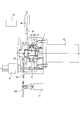
- FIG. 1 is a schematic cross-sectional view of an oil pump drive device according to an embodiment of the present invention.
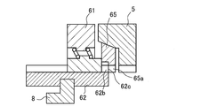
- FIG. 2 is a schematic view enlarging a part of the oil pump drive device.
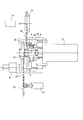
- FIG. 3 is a view showing a case where the oil pump is driven only by the electric motor.
- FIG. 4A is a view for explaining a method of engaging the second synchro gear with the hub.
- FIG. 4B is a view for explaining a method of engaging the second synchro gear with the hub.
- FIG. 4C is a view for explaining a method of engaging the second synchro gear with the hub.
- FIG. 5 is a view showing a case where the oil pump is driven only by the engine.
- FIG. 6 is a view showing a case where an oil pump is driven by an electric motor and an engine.
- FIG. 1 is a schematic cross-sectional view of an oil pump drive device.
- an oil pump drive device mounted on a vehicle will be described.
- the oil pump drive device 1 includes a rotation output unit 2, an engine rotation input unit 3, a second synchro gear 4, a first synchro gear 5, a synchro mesh mechanism 6, a motor rotation input unit 7, and a shift fork 8. And an actuator 9.
- the rotation output unit 2 includes a first input sprocket 21, a first chain 22, and a first output sprocket 23.
- the first input sprocket 21 is provided coaxially with the rotation axis O of the electric motor 12 and includes a shaft portion 21 a extending along the rotation axis O.
- One end of the shaft 21 a is rotatably supported by the case 13 and the other end is rotatably supported by the motor rotation input unit 7.
- Splines are formed on the outer peripheral wall of the shaft 21a on the electric motor 12 side, and splines formed on the hub 61 of the synchromesh mechanism 6 are fitted to the splines, and the first input sprocket 21 is integrated with the hub 61 To rotate.
- the first output sprocket 23 is connected to the drive shaft of the oil pump 11 via a connection member, and transmits the rotation transmitted via the first input sprocket 21 and the first chain 22 to the oil pump 11.
- the engine rotation input unit 3 includes a second input sprocket 31, a second chain 32, and a second output sprocket 33.
- the rotation generated by the engine 14 is transmitted to the second input sprocket 31, and the rotation generated by the engine 14 is transmitted to the second output sprocket 33 via the second chain 32.
- the second output sprocket 33 is provided coaxially with the rotation axis O, and the shaft portion 21 a of the first input sprocket 21 penetrates, and is rotatably supported by the shaft portion 21 a of the first input sprocket 21.
- the second output sprocket 33 includes a second output sprocket cylindrical portion 33 a extending along the rotation axis O from the radially inner side wall toward the electric motor 12. Splines are formed on the outer peripheral wall of the second output sprocket cylindrical portion 33a, and the splines are fitted to the splines formed on the inner peripheral wall of the second synchro gear 4, and the second output sprocket 33 and the second synchro gear 4 are Rotate together.
- the second synchro gear 4 is provided coaxially with the rotation axis O, and has a spline formed on the inner peripheral wall and fitted with a spline formed on the second output sprocket cylindrical portion 33a, and the sleeve 62 of the synchromesh mechanism 6 on the outer peripheral wall. And splines that can be fitted with the splines formed on the
- the motor rotation input unit 7 is provided coaxially with the rotation axis O, and the main shaft of the electric motor 12 is fitted and rotatably supported by the case 13.
- the motor rotation input unit 7 includes a cylindrical portion 7 a extending along the rotation axis O toward the first input sprocket 21.
- the shaft portion 21a of the first input sprocket 21 is inserted into the cylindrical portion 7a, and the cylindrical portion 7a rotatably supports the shaft portion 21a.
- a spline is formed on the outer peripheral wall of the cylindrical portion 7a, and a spline formed on the inner peripheral wall of the first synchro gear 5 is fitted to this spline, and the motor rotation input unit 7 and the first synchro gear 5 are integrally formed. Rotate.
- the first synchro gear 5 is formed on the inner peripheral wall with a spline fitted to the spline formed on the cylindrical portion 7a of the motor rotation input unit 7, and can be fitted to the spline formed on the sleeve 62 of the synchromesh mechanism 6 on the outer peripheral wall Is formed.
- FIG. 2 is a schematic view showing a part of the synchromesh mechanism 6.
- the synchromesh mechanism 6 is provided between the second synchro gear 4 and the first synchro gear 5 coaxially with the rotation axis O.
- the synchromesh mechanism 6 includes a hub 61, a sleeve 62, a synchro key 63, a second synchronizer ring 64, and a first synchronizer ring 65.
- the synchromesh mechanism 6 engages the first input sprocket 21 and at least one gear of the second synchro gear 4 and the first synchro gear 5, and the rotation generated by the engine 14 and the rotation generated by the electric motor 12 At least one of the rotations is transmitted to the oil pump 11.
- the shaft portion 21 a of the first input sprocket 21 penetrates through the hub 61, and a spline is formed on the inner peripheral wall, and this spline fits with the spline formed on the shaft portion 21 a of the first input sprocket 21.
- splines are formed on the outer peripheral wall, and the splines fit on the splines of the sleeve 62, and the hub 61 and the sleeve 62 rotate integrally.
- a plurality of notches 61 a extending in the axial direction are formed on the outer peripheral side of the hub 61, and a synchro key 63 is provided in each of the notches 61 a.
- the synchro key 63 is connected to the hub 61 via a spring 66, is biased radially outward by the spring 66, and abuts on the inner peripheral wall of the sleeve 62.
- the synchro key 63 moves in the direction of the rotational axis O together with the sleeve 62 by the frictional force generated between the synchro key 63 and the sleeve 62.
- the synchro key 63 is a second synchronizer.
- the rotational speed difference between the hub 61 and the second synchro gear 4 or the first synchro gear 5 is reduced.
- the sleeve 62 has a cylindrical shape, a spline is formed on the inner peripheral wall, and a groove 62a is formed on the outer peripheral wall along the circumferential direction.
- the shift fork 8 is engaged with the groove 62a so that the sleeve 62 can rotate with respect to the shift fork 8.
- the shift fork 8 moves in the direction of the rotation axis O
- the sleeve 62 As it moves, it moves in the direction of the rotation axis O.
- the splines formed on the inner peripheral wall of the sleeve 62 are always fitted to the splines formed on the outer peripheral wall of the hub 61, and the splines formed on the outer peripheral wall of the second synchro gear 4 in accordance with the movement of the shift fork 8. And at least one spline of the spline formed on the outer peripheral wall of the first synchro gear 5. That is, the sleeve 62 engages the hub 61 and at least one of the second synchro gear 4 and the first synchro gear 5, and the hub 61 (first input sprocket 21), the second synchro gear 4, the Synchronous rotation with at least one gear of the synchro gear 5 is performed.
- the second synchronizer ring 64 is provided between the hub 61 and the second synchro gear 4 and abuts on the second synchro gear 4 radially inward.
- the second synchronizer ring 64 includes a plurality of chamfers 64a.
- the second synchronizer ring 64 reduces the rotational speed difference between the hub 61 and the second synchro gear 4 together with the synchro key 63 when the hub 61 and the second synchro gear 4 are engaged by the sleeve 62, and the sleeve The fitting of the spline formed at 62 and the spline formed at the outer peripheral wall of the second synchro gear 4 is facilitated.
- the first synchronizer ring 65 is provided between the hub 61 and the first synchro gear 5 and abuts on the first synchro gear 5 radially inward.
- the first synchronizer ring 65 includes a plurality of chamfers 65a.
- the actuator 9 moves the sleeve 62 in the axial direction via the shift fork 8.
- the actuator 9 is, for example, a solenoid.
- FIGS. 4A to 4C a method of engaging the first synchro gear 5 with the hub 61 will be described in detail with reference to FIGS. 4A to 4C.
- the second synchro gear 4 is omitted for the sake of explanation.
- the synchronous gear 5 is rotated, and the difference in rotational speed between the hub 61 and the first synchronous gear 5 is reduced.
- the spline 62b formed on the sleeve 62 does not abut on the first synchronizer ring 65, and the frictional force between the first synchronizer ring 65 and the first synchro gear 5 is relatively small.
- the spline 62 b pushes the chamfer 65 a in the circumferential direction, and the sleeve 62 can be further moved to the first synchro gear 5 side.
- the sleeve 62 moves to the first synchro gear 5 side together with the shift fork 8
- the splines 62b formed on the inner peripheral wall of the sleeve 62 engage with the splines formed on the outer peripheral wall of the first synchro gear 5 (FIG. 4C). Since the hub 61 (sleeve 62) and the first synchro gear 5 are synchronously rotating, the splines 62b formed on the inner peripheral wall of the sleeve 62 can be easily fitted to the splines formed on the outer peripheral wall of the first synchro gear 5. . Thus, by using the synchromesh mechanism 6, the hub 61 and the first synchro gear 5 can be easily engaged.
- the rotation generated by the engine 14 is generated by the second input sprocket 31, the second chain 32, the second output sprocket 33, the second synchro gear 4, the sleeve 62, the hub 61, the first input sprocket 21, the first chain 22, the first The output sprockets 23 are sequentially transmitted to the oil pump 11.
- the oil pump 11 is driven by only the engine 14, for example, it is a case where the vehicle is traveling in a city area.
- the sleeve 62 releases the engagement between the first synchro gear 5 and the hub 61.
- the second synchro gear 4 and the hub 61 can be easily made by the same method as in the case where the first synchro gear 5 and the hub 61 are engaged. Can be engaged.
- the second synchro gear 4 and the first synchro gear 5 and the hub 61 are engaged by the sleeve 62.
- the vehicle may be accelerated.
- the rotation generated by the engine 14 is transmitted to the second input sprocket 31, the second chain 32, the second output sprocket 33, the second synchro gear 4, and the hub 61, and the rotation generated by the electric motor 12 is a motor rotation input unit
- the first input sprocket 21, the first chain 22, and the first output sprocket 23 are sequentially transmitted to the oil pump 11.
- the engagement between the second synchro gear 4 and the hub 61 can be released, the oil pump 11 and the engine 14 can be disconnected, and the load on the engine 14 can be reduced.
- the fuel consumption of the engine 14 can be improved.
- the second synchro gear 4 and the first synchro gear 5 and the hub 61 are engaged by the sleeve 62, and the oil pump 11 can be driven by the rotation generated by the engine 14 and the rotation generated by the electric motor 12.
- the drive generated by the electric motor 12 is transmitted to the oil pump 11, whereby the drive of the oil pump 11 is assisted by the electric motor 12.
- the rotation generated by the engine 14 can be used for traveling of the vehicle, and the traveling performance of the vehicle can be improved.
- the sleeve 62 When driving the oil pump 11 by the electric motor 12, the sleeve 62 transmits the hub 61 fitted to the first input sprocket 21 transmitting the rotation to the oil pump 11, and the rotation generated by the electric motor 12 is transmitted By engaging with the 1 synchro gear 5, the first synchro gear 5 and the hub 61 (first input sprocket 21) are synchronously rotated. Thus, it is possible to suppress that the rotation generated by the electric motor 12 is decelerated and transmitted to the oil pump 11. Therefore, when the oil pump 11 is driven by the electric motor 12, an increase in the rotational speed of the electric motor 12 can be suppressed, and oil pressure can be generated by the oil pump 11 without using the high-performance electric motor 12. .
- the sleeve 62 engages with the hub 61 fitted to the first input sprocket 21 transmitting the rotation to the oil pump 11, and the rotation generated by the engine 14 is transmitted
- the second synchro gear 4 and the hub 61 are synchronously rotated.
- the oil pump 11 may not be able to generate a necessary hydraulic pressure only with the engine 14.
- the necessary hydraulic pressure can be generated by the oil pump 11 by driving the electric motor 12, but the electric motor 12 consumes power.
Landscapes
- Engineering & Computer Science (AREA)
- General Engineering & Computer Science (AREA)
- Mechanical Engineering (AREA)
- Control Of Transmission Device (AREA)
- Arrangement Of Transmissions (AREA)
Abstract
Description
Claims (2)
- 電動モータによって発生した回転、エンジンによって発生した回転のうち少なくとも一方の回転によってオイルポンプを駆動させるオイルポンプ駆動装置であって、
前記電動モータによって発生した回転が伝達される第1伝達部と、
前記エンジンによって発生した回転が伝達される第2伝達部と、
前記オイルポンプに回転を伝達する第3伝達部と、
前記第3伝達部を、前記第1伝達部、前記第2伝達部、または前記第1伝達部と前記第2伝達部に係合させる係合手段とを備えるオイルポンプ駆動装置。 - 請求項1に記載のオイルポンプ駆動装置であって、
前記係合手段は、シンクロメッシュ機構であるオイルポンプ駆動装置。
Priority Applications (5)
| Application Number | Priority Date | Filing Date | Title |
|---|---|---|---|
| EP14774541.8A EP2980449A1 (en) | 2013-03-25 | 2014-01-29 | Oil pump-driving apparatus |
| CN201480016793.4A CN105051413A (zh) | 2013-03-25 | 2014-01-29 | 油泵驱动装置 |
| JP2015508128A JPWO2014156280A1 (ja) | 2013-03-25 | 2014-01-29 | オイルポンプ駆動装置 |
| US14/778,220 US20160273533A1 (en) | 2013-03-25 | 2014-01-29 | Oil pump-driving apparatus |
| KR1020157021885A KR20150110596A (ko) | 2013-03-25 | 2014-01-29 | 오일 펌프 구동 장치 |
Applications Claiming Priority (2)
| Application Number | Priority Date | Filing Date | Title |
|---|---|---|---|
| JP2013-062498 | 2013-03-25 | ||
| JP2013062498 | 2013-03-25 |
Publications (1)
| Publication Number | Publication Date |
|---|---|
| WO2014156280A1 true WO2014156280A1 (ja) | 2014-10-02 |
Family
ID=51623282
Family Applications (1)
| Application Number | Title | Priority Date | Filing Date |
|---|---|---|---|
| PCT/JP2014/051912 Ceased WO2014156280A1 (ja) | 2013-03-25 | 2014-01-29 | オイルポンプ駆動装置 |
Country Status (6)
| Country | Link |
|---|---|
| US (1) | US20160273533A1 (ja) |
| EP (1) | EP2980449A1 (ja) |
| JP (1) | JPWO2014156280A1 (ja) |
| KR (1) | KR20150110596A (ja) |
| CN (1) | CN105051413A (ja) |
| WO (1) | WO2014156280A1 (ja) |
Cited By (1)
| Publication number | Priority date | Publication date | Assignee | Title |
|---|---|---|---|---|
| EP3179135A1 (en) * | 2015-12-09 | 2017-06-14 | MAHLE Filter Systems Japan Corporation | Oil pump device |
Citations (5)
| Publication number | Priority date | Publication date | Assignee | Title |
|---|---|---|---|---|
| JPH06174055A (ja) * | 1992-12-10 | 1994-06-21 | Honda Motor Co Ltd | 変速機におけるオイルポンプ駆動装置 |
| JPH0989004A (ja) * | 1995-09-27 | 1997-03-31 | Nissan Diesel Motor Co Ltd | シンクロ機構の冷却装置 |
| JPH10169485A (ja) * | 1995-06-06 | 1998-06-23 | Aqueous Res:Kk | ハイブリッド車両 |
| JP2001289315A (ja) | 2000-04-05 | 2001-10-19 | Fuji Heavy Ind Ltd | 自動車用自動変速装置 |
| JP2003220843A (ja) * | 2001-11-22 | 2003-08-05 | Honda Motor Co Ltd | エンジンシステムとその運転方法およびエンジン始動装置 |
Family Cites Families (2)
| Publication number | Priority date | Publication date | Assignee | Title |
|---|---|---|---|---|
| CN2296419Y (zh) * | 1996-10-23 | 1998-11-04 | 周干绪 | 一种新结构的单螺杆潜油泵驱动装置 |
| CN2613594Y (zh) * | 2003-03-20 | 2004-04-28 | 山东巨菱股份有限公司 | 单缸卧式柴油机机油泵驱动装置 |
-
2014
- 2014-01-29 WO PCT/JP2014/051912 patent/WO2014156280A1/ja not_active Ceased
- 2014-01-29 CN CN201480016793.4A patent/CN105051413A/zh active Pending
- 2014-01-29 US US14/778,220 patent/US20160273533A1/en not_active Abandoned
- 2014-01-29 EP EP14774541.8A patent/EP2980449A1/en not_active Withdrawn
- 2014-01-29 JP JP2015508128A patent/JPWO2014156280A1/ja active Pending
- 2014-01-29 KR KR1020157021885A patent/KR20150110596A/ko not_active Withdrawn
Patent Citations (5)
| Publication number | Priority date | Publication date | Assignee | Title |
|---|---|---|---|---|
| JPH06174055A (ja) * | 1992-12-10 | 1994-06-21 | Honda Motor Co Ltd | 変速機におけるオイルポンプ駆動装置 |
| JPH10169485A (ja) * | 1995-06-06 | 1998-06-23 | Aqueous Res:Kk | ハイブリッド車両 |
| JPH0989004A (ja) * | 1995-09-27 | 1997-03-31 | Nissan Diesel Motor Co Ltd | シンクロ機構の冷却装置 |
| JP2001289315A (ja) | 2000-04-05 | 2001-10-19 | Fuji Heavy Ind Ltd | 自動車用自動変速装置 |
| JP2003220843A (ja) * | 2001-11-22 | 2003-08-05 | Honda Motor Co Ltd | エンジンシステムとその運転方法およびエンジン始動装置 |
Cited By (1)
| Publication number | Priority date | Publication date | Assignee | Title |
|---|---|---|---|---|
| EP3179135A1 (en) * | 2015-12-09 | 2017-06-14 | MAHLE Filter Systems Japan Corporation | Oil pump device |
Also Published As
| Publication number | Publication date |
|---|---|
| KR20150110596A (ko) | 2015-10-02 |
| EP2980449A1 (en) | 2016-02-03 |
| CN105051413A (zh) | 2015-11-11 |
| US20160273533A1 (en) | 2016-09-22 |
| JPWO2014156280A1 (ja) | 2017-02-16 |
Similar Documents
| Publication | Publication Date | Title |
|---|---|---|
| US8919515B2 (en) | Clutch device | |
| US9360110B2 (en) | Transmission apparatus | |
| KR101500204B1 (ko) | 차량의 하이브리드 파워트레인 | |
| KR101518948B1 (ko) | 차량의 변속장치 | |
| KR20160073234A (ko) | 하이브리드 차량용 구동장치 | |
| EP3256755B1 (en) | Twin countershaft transmission with spline | |
| KR102698862B1 (ko) | 하이브리드 차량 파워트레인용 클러치 장치 | |
| WO2011037023A1 (ja) | 車両用電動モータ駆動装置 | |
| US9885395B2 (en) | Selectable one-way clutch | |
| KR101416424B1 (ko) | 자동차의 더블 클러치 변속기 | |
| JPWO2016152286A1 (ja) | 自動変速機 | |
| WO2012133621A1 (ja) | 変速機 | |
| JP5425696B2 (ja) | ワンウェイクラッチを用いたエンジンスタータ機構 | |
| CN109073076B (zh) | 切换组件 | |
| KR101103969B1 (ko) | Dct 클러치 작동기구 | |
| WO2014156280A1 (ja) | オイルポンプ駆動装置 | |
| CN103459830A (zh) | 发动机启动装置 | |
| JP2014029167A (ja) | 動力伝達装置 | |
| JP2000274446A (ja) | ドッグクラッチ機構およびこのドッグクラッチ機構を用いた自動変速機 | |
| KR20150125089A (ko) | 하이브리드 변속기 | |
| KR101611047B1 (ko) | 더블 클러치 변속기 | |
| JP2014142013A (ja) | 変速機構造 | |
| JP7109356B2 (ja) | オイルポンプ駆動装置 | |
| KR102355557B1 (ko) | 전동식 조향장치 | |
| JP2014114892A (ja) | 変速機構造 |
Legal Events
| Date | Code | Title | Description |
|---|---|---|---|
| WWE | Wipo information: entry into national phase |
Ref document number: 201480016793.4 Country of ref document: CN |
|
| 121 | Ep: the epo has been informed by wipo that ep was designated in this application |
Ref document number: 14774541 Country of ref document: EP Kind code of ref document: A1 |
|
| ENP | Entry into the national phase |
Ref document number: 20157021885 Country of ref document: KR Kind code of ref document: A |
|
| REEP | Request for entry into the european phase |
Ref document number: 2014774541 Country of ref document: EP |
|
| WWE | Wipo information: entry into national phase |
Ref document number: 2014774541 Country of ref document: EP |
|
| ENP | Entry into the national phase |
Ref document number: 2015508128 Country of ref document: JP Kind code of ref document: A |
|
| WWE | Wipo information: entry into national phase |
Ref document number: 14778220 Country of ref document: US |
|
| NENP | Non-entry into the national phase |
Ref country code: DE |