WO2014156561A1 - クライオスタット - Google Patents
クライオスタット Download PDFInfo
- Publication number
- WO2014156561A1 WO2014156561A1 PCT/JP2014/055966 JP2014055966W WO2014156561A1 WO 2014156561 A1 WO2014156561 A1 WO 2014156561A1 JP 2014055966 W JP2014055966 W JP 2014055966W WO 2014156561 A1 WO2014156561 A1 WO 2014156561A1
- Authority
- WO
- WIPO (PCT)
- Prior art keywords
- tank
- helium
- liquefaction chamber
- refrigerator
- refrigerant
- Prior art date
- Legal status (The legal status is an assumption and is not a legal conclusion. Google has not performed a legal analysis and makes no representation as to the accuracy of the status listed.)
- Ceased
Links
Images


Classifications
-
- H—ELECTRICITY
- H01—ELECTRIC ELEMENTS
- H01F—MAGNETS; INDUCTANCES; TRANSFORMERS; SELECTION OF MATERIALS FOR THEIR MAGNETIC PROPERTIES
- H01F6/00—Superconducting magnets; Superconducting coils
- H01F6/04—Cooling
-
- F—MECHANICAL ENGINEERING; LIGHTING; HEATING; WEAPONS; BLASTING
- F17—STORING OR DISTRIBUTING GASES OR LIQUIDS
- F17C—VESSELS FOR CONTAINING OR STORING COMPRESSED, LIQUEFIED OR SOLIDIFIED GASES; FIXED-CAPACITY GAS-HOLDERS; FILLING VESSELS WITH, OR DISCHARGING FROM VESSELS, COMPRESSED, LIQUEFIED, OR SOLIDIFIED GASES
- F17C3/00—Vessels not under pressure
- F17C3/02—Vessels not under pressure with provision for thermal insulation
- F17C3/08—Vessels not under pressure with provision for thermal insulation by vacuum spaces, e.g. Dewar flask
- F17C3/085—Cryostats
-
- F—MECHANICAL ENGINEERING; LIGHTING; HEATING; WEAPONS; BLASTING
- F25—REFRIGERATION OR COOLING; COMBINED HEATING AND REFRIGERATION SYSTEMS; HEAT PUMP SYSTEMS; MANUFACTURE OR STORAGE OF ICE; LIQUEFACTION SOLIDIFICATION OF GASES
- F25D—REFRIGERATORS; COLD ROOMS; ICE-BOXES; COOLING OR FREEZING APPARATUS NOT OTHERWISE PROVIDED FOR
- F25D19/00—Arrangement or mounting of refrigeration units with respect to devices or objects to be refrigerated, e.g. infrared detectors
-
- F—MECHANICAL ENGINEERING; LIGHTING; HEATING; WEAPONS; BLASTING
- F25—REFRIGERATION OR COOLING; COMBINED HEATING AND REFRIGERATION SYSTEMS; HEAT PUMP SYSTEMS; MANUFACTURE OR STORAGE OF ICE; LIQUEFACTION SOLIDIFICATION OF GASES
- F25D—REFRIGERATORS; COLD ROOMS; ICE-BOXES; COOLING OR FREEZING APPARATUS NOT OTHERWISE PROVIDED FOR
- F25D3/00—Devices using other cold materials; Devices using cold-storage bodies
- F25D3/10—Devices using other cold materials; Devices using cold-storage bodies using liquefied gases, e.g. liquid air
- F25D3/107—Devices using other cold materials; Devices using cold-storage bodies using liquefied gases, e.g. liquid air portable, i.e. adapted to be carried personally
-
- F—MECHANICAL ENGINEERING; LIGHTING; HEATING; WEAPONS; BLASTING
- F17—STORING OR DISTRIBUTING GASES OR LIQUIDS
- F17C—VESSELS FOR CONTAINING OR STORING COMPRESSED, LIQUEFIED OR SOLIDIFIED GASES; FIXED-CAPACITY GAS-HOLDERS; FILLING VESSELS WITH, OR DISCHARGING FROM VESSELS, COMPRESSED, LIQUEFIED, OR SOLIDIFIED GASES
- F17C2221/00—Handled fluid, in particular type of fluid
- F17C2221/01—Pure fluids
- F17C2221/016—Noble gases (Ar, Kr, Xe)
- F17C2221/017—Helium
-
- F—MECHANICAL ENGINEERING; LIGHTING; HEATING; WEAPONS; BLASTING
- F17—STORING OR DISTRIBUTING GASES OR LIQUIDS
- F17C—VESSELS FOR CONTAINING OR STORING COMPRESSED, LIQUEFIED OR SOLIDIFIED GASES; FIXED-CAPACITY GAS-HOLDERS; FILLING VESSELS WITH, OR DISCHARGING FROM VESSELS, COMPRESSED, LIQUEFIED, OR SOLIDIFIED GASES
- F17C2270/00—Applications
- F17C2270/05—Applications for industrial use
- F17C2270/0509—"Dewar" vessels
-
- F—MECHANICAL ENGINEERING; LIGHTING; HEATING; WEAPONS; BLASTING
- F25—REFRIGERATION OR COOLING; COMBINED HEATING AND REFRIGERATION SYSTEMS; HEAT PUMP SYSTEMS; MANUFACTURE OR STORAGE OF ICE; LIQUEFACTION SOLIDIFICATION OF GASES
- F25B—REFRIGERATION MACHINES, PLANTS OR SYSTEMS; COMBINED HEATING AND REFRIGERATION SYSTEMS; HEAT PUMP SYSTEMS
- F25B2400/00—Component parts or details not otherwise provided for in this subclass
- F25B2400/17—Re-condensers
-
- F—MECHANICAL ENGINEERING; LIGHTING; HEATING; WEAPONS; BLASTING
- F25—REFRIGERATION OR COOLING; COMBINED HEATING AND REFRIGERATION SYSTEMS; HEAT PUMP SYSTEMS; MANUFACTURE OR STORAGE OF ICE; LIQUEFACTION SOLIDIFICATION OF GASES
- F25B—REFRIGERATION MACHINES, PLANTS OR SYSTEMS; COMBINED HEATING AND REFRIGERATION SYSTEMS; HEAT PUMP SYSTEMS
- F25B2500/00—Problems to be solved
- F25B2500/13—Vibrations
-
- F—MECHANICAL ENGINEERING; LIGHTING; HEATING; WEAPONS; BLASTING
- F25—REFRIGERATION OR COOLING; COMBINED HEATING AND REFRIGERATION SYSTEMS; HEAT PUMP SYSTEMS; MANUFACTURE OR STORAGE OF ICE; LIQUEFACTION SOLIDIFICATION OF GASES
- F25B—REFRIGERATION MACHINES, PLANTS OR SYSTEMS; COMBINED HEATING AND REFRIGERATION SYSTEMS; HEAT PUMP SYSTEMS
- F25B9/00—Compression machines, plants or systems, in which the refrigerant is air or other gas of low boiling point
- F25B9/14—Compression machines, plants or systems, in which the refrigerant is air or other gas of low boiling point characterised by the cycle used, e.g. Stirling cycle
- F25B9/145—Compression machines, plants or systems, in which the refrigerant is air or other gas of low boiling point characterised by the cycle used, e.g. Stirling cycle pulse-tube cycle
Definitions
- the present invention relates to a cryostat for cooling a superconducting magnet or the like.
- a refrigerator that recondenses evaporated refrigerant is used in order to reduce consumption of liquid helium, which is a refrigerant.
- magnetic field disturbance is generated by vibration from the refrigerator, there is a problem that noise is generated in the NMR signal obtained by the NMR apparatus.
- Patent Document 1 a plug provided with a large number of holes whose diameter is sufficiently smaller than the wavelength of the acoustic wave generated by the refrigerator, a liquefaction chamber that houses the lower part of the refrigerator, and a refrigerant that contains liquid helium
- a cryostat assembly provided in a passage connecting the tank is disclosed.
- Helium gas generated by the evaporation of liquid helium in the refrigerant tank enters the liquefaction chamber through a number of holes.
- Liquid helium produced by reliquefaction of helium gas in the liquefaction chamber returns to the refrigerant tank through a number of holes.
- produced with the refrigerator is attenuate
- the plug of Patent Document 1 has the following problems. That is, the refrigerant tank is temporarily opened during maintenance of the refrigerator. At this time, there is a possibility that minute air is mixed in the refrigerant tank. The air mixed in the refrigerant tank is cooled and condensed by the refrigerant and stays in the refrigerant tank. In the unlikely event that the condensed air closes a large number of holes in the plug, the passage between the refrigerant tank and the liquefaction chamber is blocked, resulting in a fatal failure in the recondensing function.
- An object of the present invention is to provide a cryostat capable of reducing vibrations derived from a refrigerator.
- the cryostat according to the present invention accommodates a refrigerant tank that stores a liquid refrigerant, a refrigerator that is provided above the refrigerant tank and reliquefies the refrigerant evaporated in the refrigerant tank, and a lower part of the refrigerator.
- the refrigerant means and the liquefaction chamber are configured such that the accommodating means for accommodating the gaseous refrigerant communicates with at least one of the space above the liquid level of the liquid refrigerant in the refrigerant tank and the liquefaction chamber.
- the volume of the gas phase increases.
- the acoustic vibration (pressure fluctuation) from the refrigerator is caused by the liquefaction cycle of the refrigerator, the pressure fluctuation tends to be suppressed as the gas phase volume is larger than the liquefaction amount per unit time. Therefore, it is conceivable to increase the volume of the gas phase by enlarging the refrigerant tank and the liquefaction chamber itself.
- the cryostat becomes larger and a larger installation area is required. Moreover, heat penetration increases by increasing the surface area of the cryostat, increasing the load on the refrigerator. Then, the accommodating means which accommodates gaseous refrigerant is connected to a refrigerant tank or a liquefaction chamber, and the pressure fluctuation from a refrigerator is suppressed by enlarging a gas phase volume with an accommodating means. Thereby, the vibration originating in a refrigerator can be reduced.
- a cryostat 100 includes a helium tank (refrigerant tank) 2 that stores liquid helium, which is a liquid refrigerant, and a refrigerator 5 provided above the helium tank 2. And a cylindrical member 15 that forms a liquefaction chamber 8 that communicates with the helium tank 2, and a buffer tank (accommodating means) 10 that communicates with the liquefaction chamber 8.
- the cryostat 100 of the present embodiment is used for an NMR apparatus, but is not limited thereto, and may be used for an MRI apparatus, for example. Further, the refrigerant is not limited to helium.
- the helium tank 2 is provided with a gas discharge port (not shown).
- This gas discharge port is a path through which helium gas evaporates when the capacity of the refrigerator 5 is lost, and is provided at the upper end of a cylindrical member 13 described later.
- a check valve for preventing air from entering the helium tank 2 from the outside is attached to the upper side of the gas discharge port. Therefore, even if the helium gas in the helium tank 2 is cooled by the refrigerator 5 and liquefied, the total amount of helium in the helium tank 2 does not change.
- the pressure in the helium tank 2 is controlled to a positive pressure slightly higher than the atmospheric pressure. Examples of the material of the helium tank 2 include aluminum and stainless steel.
- a superconducting magnet 1 is accommodated in the helium tank 2.
- the superconducting magnet 1 is formed by spirally winding a superconducting wire around a winding frame (not shown).
- the superconducting wire may be a metal-based superconducting wire or an oxide-based superconducting wire.
- a cylindrical space S (bore) extending in the vertical direction is provided at the center of the helium tank 2. A sample is placed in the cylindrical space S, and various analyzes and experiments are performed.
- the helium tank 2 is surrounded by a radiation shield 3.
- the radiation shield 3 is a shield container that is cooled by the cold heat of the helium gas so as not to let the cold heat escape. Further, the radiation shield 3 is forcibly cooled by a first cooling stage 6 described later of the refrigerator 5. Examples of the material of the radiation shield 3 include aluminum and copper.
- the vacuum container 4 is a container whose inside is maintained at a high vacuum and suppresses heat intrusion into the superconducting magnet 1 and the helium tank 2.
- a neck member 12 having a cylindrical member 13 inside is attached to the upper portion of the vacuum vessel 4.
- the cylindrical member 13 is used as a passage for inserting a current lead (not shown) or a replenishment passage for liquid helium into the helium tank 2.
- the vacuum vessel 4 is supported on the floor by a plurality of stands 9. Examples of the material of the vacuum vessel 4 include aluminum and stainless steel.
- the refrigerator 5 is for reliquefying the liquid helium evaporated in the helium tank 2, and a pulse tube refrigerator is used in this embodiment.
- a first cooling stage 6 (1nd stage) is provided in the middle part of the refrigerator 5 in the vertical direction, and a second cooling stage 7 (2nd stage) is provided at the lower end of the refrigerator 5.
- Each of the first cooling stage 6 and the second cooling stage 7 has a flange shape, and is cooled by the refrigerator 5 to, for example, about 40K and about 4K, respectively.
- the material of the first cooling stage 6 and the second cooling stage 7 is mainly copper or a copper alloy.
- the refrigerator 5 is not limited to the pulse tube refrigerator, and may be a GM refrigerator, a Stirling refrigerator, or the like.
- the cylindrical member 15 accommodates the lower part including the second cooling stage 7 in the refrigerator 5.
- a tubular member 16 is further disposed outside the tubular member 15.
- the internal space of the tubular member 15 is a liquefaction chamber 8, and the liquefaction chamber 8 and the helium tank 2 are communicated with each other by a tubular communication member 14 having a smaller diameter than the tubular member 15.
- the buffer tank 10 has a larger gas phase volume than the helium tank 2 and the liquefaction chamber 8, and contains helium gas which is a gaseous refrigerant.
- the gas phase volume of the liquefaction chamber 8 is 3.5 L, whereas the gas phase volume of the buffer tank 10 is 250 L.
- the buffer tank 10 is installed on the floor. Such a buffer tank 10 communicates with the liquefaction chamber 8 via the communication path 11, so that the gas phase volume of the liquefaction chamber 8 is increased.
- Examples of the material of the buffer tank 10 include aluminum and stainless steel.
- the acoustic vibration (pressure fluctuation) from the refrigerator 5 is caused by the liquefaction cycle of the refrigerator 5.
- the pressure fluctuation tends to be suppressed as the gas phase volume is larger than the liquefaction amount per unit time.
- it is conceivable to increase the volume of the gas phase by increasing the size of the helium tank 2 or the liquefaction chamber 8 itself.
- the cryostat 100 becomes larger and a larger installation area is required.
- heat penetration increases by increasing the surface area of the cryostat 100, and the load on the refrigerator 5 increases.
- the buffer tank 10 is connected to the liquefaction chamber 8, and the gas phase volume of the liquefaction chamber 8 is increased by the buffer tank 10, thereby suppressing the pressure fluctuation from the refrigerator 5.
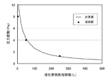
- Fig. 2 shows the calculated and measured values of pressure fluctuation. It can be seen that the pressure fluctuation tends to be suppressed as the gas phase volume on the liquefying chamber 8 side is larger.
- the peak peak value of pressure fluctuation when the buffer tank 10 is not connected to the liquefaction chamber 8 is about 6 Pa, whereas the peak peak value of pressure fluctuation when the buffer tank 10 is connected to the liquefaction chamber 8 is 1.3 Pa. It was about. From this, it can be seen that the pressure fluctuation is suppressed by increasing the gas phase volume of the liquefaction chamber 8 in the buffer tank 10.
- the buffer tank 10 that stores helium gas is disposed in the space above the liquid level of liquid helium in the helium tank 2 and at least the liquefaction chamber 8.
- the gas phase volume of the helium tank 2 or the liquefaction chamber 8 is increased.
- the acoustic vibration (pressure fluctuation) from the refrigerator 5 is caused by the liquefaction cycle of the refrigerator 5, the pressure fluctuation tends to be suppressed as the gas phase volume is larger than the liquefaction amount per unit time. is there.
- it is conceivable to increase the volume of the gas phase by increasing the size of the helium tank 2 or the liquefaction chamber 8 itself.
- the cryostat 100 becomes larger and a larger installation area is required. Moreover, heat penetration increases by increasing the surface area of the cryostat 100, and the load on the refrigerator 5 increases. Therefore, the buffer tank 10 is connected to the helium tank 2 and the liquefaction chamber 8, and the pressure fluctuation from the refrigerator 5 is suppressed by increasing the gas phase volume in the buffer tank 10. Thereby, the vibration originating in the refrigerator 5 can be reduced.
- the buffer tank 10 is communicated with the liquefaction chamber 8. Since the liquefaction chamber 8 has a smaller gas phase volume than the helium tank 2, pressure fluctuation is more easily transmitted than the helium tank 2. Therefore, in order to make it difficult to transmit the pressure fluctuation, it is more effective to increase the gas phase volume on the liquefaction chamber 8 side than to increase the gas phase volume on the helium tank 2 side. Therefore, the buffer tank 10 is communicated with the liquefaction chamber 8 to increase the gas phase volume on the liquefaction chamber 8 side. Thereby, the pressure fluctuation from the refrigerator 5 can be suppressed suitably.
- the noise that appears in the NMR signal can be reduced by reducing the vibration derived from the refrigerator 5.
- the buffer tank 10 is used as the storage means for storing the helium gas, but the storage means is not limited to the container, and may be a bag or an airtight chamber.
- the buffer tank 10 is communicated with the liquefaction chamber 8, but the buffer tank 10 may be communicated with both the helium tank 2 and the liquefaction chamber 8.
Landscapes
- Engineering & Computer Science (AREA)
- Physics & Mathematics (AREA)
- Mechanical Engineering (AREA)
- Thermal Sciences (AREA)
- General Engineering & Computer Science (AREA)
- Chemical & Material Sciences (AREA)
- Combustion & Propulsion (AREA)
- Power Engineering (AREA)
- Containers, Films, And Cooling For Superconductive Devices (AREA)
Abstract
冷凍機に由来する振動を低減させることができるようにする。 液体ヘリウムを収容するヘリウム槽2と、ヘリウム槽2の上方に設けられ、ヘリウム槽2内で蒸発した液体ヘリウムを再液化させる冷凍機5と、冷凍機5の下部を収容してヘリウム槽2に連通する液化室8を形成する筒状部材15と、ヘリウム槽2内における液体ヘリウムの液面よりも上方の空間、および、液化室8の少なくとも一方に連通し、ヘリウムガスを収容するバッファタンク10と、を有する。ヘリウム槽2や液化室8にバッファタンク10を連通させることで、ヘリウム槽2や液化室8の気相容積が大きくなる。
Description
本発明は、超電導マグネット等を冷却するためのクライオスタットに関する。
NMR装置等に適用される超電導マグネット装置においては、冷媒である液体ヘリウムの消費をゼロにするために、蒸発した冷媒を再凝縮する冷凍機が用いられる。しかし、冷凍機からの振動で磁場擾乱が発生するために、NMR装置で得られるNMR信号にノイズが発生するという問題がある。
そこで、特許文献1には、冷凍機が発生させる音響波の波長よりも直径が十分に小さい孔が多数設けられたプラグを、冷凍機の下部を収容する液化室と、液体ヘリウムを収容する冷媒槽とをつなぐ通路に設けたクライオスタットアセンブリが開示されている。冷媒槽内で液体ヘリウムが蒸発することで生じたヘリウムガスは、多数の孔を通って液化室に入る。液化室内でヘリウムガスが再液化することで生じた液体ヘリウムは、多数の孔を通って冷媒槽に戻る。そして、冷凍機で発生した音響波は、多数の孔を通過する際に減衰されることとなる。
しかしながら、特許文献1のプラグには、以下のような問題点がある。即ち、冷凍機のメンテナンス時に、冷媒槽は一時的に開放される。このときに、冷媒槽内に微少な空気が混入する可能性がある。冷媒槽内に混入した空気は冷媒で冷却されて凝縮し、冷媒槽内に留まる。この凝縮した空気が、万一プラグの多数の孔を閉塞させた場合には、冷媒槽と液化室との通路が遮断され、再凝縮機能に致命的な不全が生じる。
本発明の目的は、冷凍機に由来する振動を低減させることが可能なクライオスタットを提供することである。
本発明におけるクライオスタットは、液体の冷媒を収容する冷媒槽と、前記冷媒槽の上方に設けられ、前記冷媒槽内で蒸発した冷媒を再液化させる冷凍機と、前記冷凍機の下部を収容して前記冷媒槽に連通する液化室を形成する筒状部材と、前記冷媒槽内における液体の冷媒の液面よりも上方の空間、および、前記液化室の少なくとも一方に連通し、気体の冷媒を収容する収容手段と、を有することを特徴とする。
本発明によれば、気体の冷媒を収容する収容手段を、冷媒槽内における液体の冷媒の液面よりも上方の空間、および、液化室の少なくとも一方に連通させることで、冷媒槽や液化室の気相容積が大きくなる。ここで、冷凍機からの音響振動(圧力変動)は、冷凍機の液化サイクルにより引き起こされるが、単位時間当たりの液化量に対して気相容積が大きいほど圧力変動は抑制される傾向にある。そこで、冷媒槽や液化室そのものを大きくすることで、気相容積を大きくすることが考えられる。しかし、冷媒槽や液化室そのものを大きくすると、クライオスタットが大型化し、より大きな設置面積が必要となる。また、クライオスタットの表面積が大きくなることで熱侵入が増加し、冷凍機への負荷が大きくなる。そこで、気体の冷媒を収容する収容手段を冷媒槽や液化室に接続し、収容手段で気相容積を大きくすることで、冷凍機からの圧力変動を抑制する。これにより、冷凍機に由来する振動を低減させることができる。
以下、本発明の好適な実施の形態について、図面を参照しつつ説明する。
(クライオスタットの構成)
本発明の第1実施形態によるクライオスタット100は、図1に示すように、液体の冷媒である液体ヘリウムを収容するヘリウム槽(冷媒槽)2と、ヘリウム槽2の上方に設けられた冷凍機5と、ヘリウム槽2に連通する液化室8を形成する筒状部材15と、液化室8に連通するバッファタンク(収容手段)10と、を有している。なお、本実施形態のクライオスタット100は、NMR装置に用いられるものであるが、これに限定されず、例えば、MRI装置に用いられるものであってもよい。また、冷媒はヘリウムに限定されない。
本発明の第1実施形態によるクライオスタット100は、図1に示すように、液体の冷媒である液体ヘリウムを収容するヘリウム槽(冷媒槽)2と、ヘリウム槽2の上方に設けられた冷凍機5と、ヘリウム槽2に連通する液化室8を形成する筒状部材15と、液化室8に連通するバッファタンク(収容手段)10と、を有している。なお、本実施形態のクライオスタット100は、NMR装置に用いられるものであるが、これに限定されず、例えば、MRI装置に用いられるものであってもよい。また、冷媒はヘリウムに限定されない。
ヘリウム槽2にはガス放出口(図示せず)が設けられている。このガス放出口は、冷凍機5の能力を喪失した際にヘリウムガスが蒸発する経路であり、後述する筒部材13の上端部に設けられている。このガス放出口の上側には、外部からヘリウム槽2内への空気の混入を防止するための逆止弁が取り付けられている。そのため、ヘリウム槽2内のヘリウムガスが冷凍機5によって冷却されて液化してもヘリウム槽2内の総ヘリウム量は変化しない。また、ヘリウム槽2内への空気の混入を防止するために、ヘリウム槽2内の圧力は、大気圧よりも僅かに高い正圧に制御されている。ヘリウム槽2の材質としては、アルミニウム、ステンレスなどが挙げられる。
ヘリウム槽2内には、超電導マグネット1が収容されている。超電導マグネット1は、超電導線材を巻枠(図示せず)に螺旋状に巻回してなるものである。超電導線材は、金属系超電導線材であってもよいし、酸化物系超電導線材であってもよい。また、ヘリウム槽2の中心部には、鉛直方向に延びる円筒空間S(ボア)が設けられている。この円筒空間Sに試料が入れられ、様々な分析・実験が行われる。
ヘリウム槽2は、輻射シールド3で囲まれている。この輻射シールド3は、冷熱をより逃がさないようにするための、ヘリウムガスの有する冷熱で冷却されるシールド容器である。また、輻射シールド3は、冷凍機5の後述する第1冷却ステージ6により強制冷却されている。輻射シールド3の材質としては、アルミニウム、銅などが挙げられる。
また、ヘリウム槽2および輻射シールド3は、真空容器4内に収容されている。この真空容器4は、その内部を高真空に保持され、超電導マグネット1やヘリウム槽2への熱侵入を抑制する容器である。真空容器4の上部には、内部に筒部材13を有するネック部材12が取り付けられている。筒部材13は、電流リード(図示せず)の挿入通路として用いられたり、ヘリウム槽2内への液体ヘリウムの補充通路として用いられたりする。また、真空容器4は、複数のスタンド9によって床上に支持されている。真空容器4の材質としては、アルミニウム、ステンレスなどが挙げられる。
冷凍機5は、ヘリウム槽2内で蒸発した液体ヘリウムを再液化させるためのものであり、本実施形態ではパルスチューブ冷凍機が用いられている。冷凍機5の鉛直方向における中途部には第1冷却ステージ6(1ndステージ)が設けられ、冷凍機5の下端部には第2冷却ステージ7(2ndステージ)が設けられている。第1冷却ステージ6および第2冷却ステージ7は、いずれもフランジ状の形態を有しており、冷凍機5により冷却されて、それぞれ、例えば約40Kおよび約4Kになる。第1冷却ステージ6および第2冷却ステージ7の材質は、主に銅や銅合金である。なお、冷凍機5は、パルスチューブ冷凍機に限定されず、GM冷凍機やスターリング冷凍機などであってもよい。
筒状部材15は、冷凍機5における第2冷却ステージ7を含む下部を収容している。この筒状部材15の外側にはさらに筒状部材16が配置されている。この筒状部材15の内部空間が液化室8であり、この液化室8とヘリウム槽2とは、筒状部材15よりも小径の筒状の連通部材14で連通されている。
バッファタンク10は、ヘリウム槽2や液化室8よりも気相容積が大きく、気体の冷媒であるヘリウムガスを収容している。本実施形態において、液化室8の気相容積が3.5Lであるのに対して、バッファタンク10の気相容積は250Lである。このバッファタンク10は、床上に設置されている。このようなバッファタンク10が連通路11を介して液化室8に連通されることで、液化室8の気相容積が大きくされている。バッファタンク10の材質としては、アルミニウム、ステンレスなどが挙げられる。
ここで、冷凍機5からの音響振動(圧力変動)は、冷凍機5の液化サイクルにより引き起こされる。ところが、単位時間当たりの液化量に対して気相容積が大きいほど圧力変動は抑制される傾向にある。そこで、ヘリウム槽2や液化室8そのものを大きくすることで、気相容積を大きくすることが考えられる。しかし、ヘリウム槽2や液化室8そのものを大きくすると、クライオスタット100が大型化し、より大きな設置面積が必要となる。また、クライオスタット100の表面積が大きくなることで熱侵入が増加し、冷凍機5への負荷が大きくなる。
そこで、本実施形態においては、液化室8にバッファタンク10を接続し、バッファタンク10で液化室8の気相容積を大きくすることで、冷凍機5からの圧力変動を抑制している。
なお、ヘリウム槽2内における液体ヘリウムの液面よりも上方の空間にバッファタンク10を連通させて、ヘリウム槽2の気相容積を大きくしても、冷凍機5からの圧力変動を抑制することができる。ただし、液化室8はヘリウム槽2よりも容量が小さいために、ヘリウム槽2よりも圧力変動が伝わりやすい。よって、圧力変動を伝わりにくくするには、ヘリウム槽2側の気相容積を大きくするよりも、液化室8側の気相容積を大きくする方が効果的である。
(圧力変動評価)
次に、液化室8側の気相容積を変化させたときの冷凍機5からの圧力変動の値を評価した。まず、計算モデルを用いて圧力変動の計算値を求めた。その結果を表1に示す。
次に、液化室8側の気相容積を変化させたときの冷凍機5からの圧力変動の値を評価した。まず、計算モデルを用いて圧力変動の計算値を求めた。その結果を表1に示す。
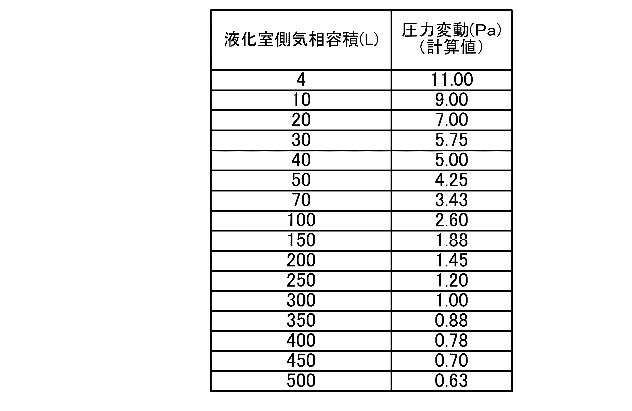
次に、実際に液化室8側の気相容積を変化させて、圧力変動の実測値を測定した。その結果を表2に示す。

圧力変動の計算値および実測値を図2に示す。液化室8側の気相容積が大きいほど圧力変動は抑制される傾向にあることがわかる。
(圧力変動の時間変化)
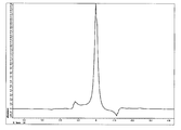
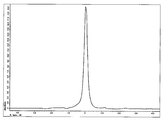
次に、バッファタンク10を液化室8に接続したときと、接続しないときとで、ヘリウム槽2内の圧力変動の時間変化を測定した。測定条件として、バッファタンク10の容量(気相容積)を250Lとし、ヘリウム槽2内の液体ヘリウムの液面高さをヘリウム槽2内部の全高の69%とし、ヘリウム槽2のベース圧力を2.3kPaとした。測定結果を図3に示す。
次に、バッファタンク10を液化室8に接続したときと、接続しないときとで、ヘリウム槽2内の圧力変動の時間変化を測定した。測定条件として、バッファタンク10の容量(気相容積)を250Lとし、ヘリウム槽2内の液体ヘリウムの液面高さをヘリウム槽2内部の全高の69%とし、ヘリウム槽2のベース圧力を2.3kPaとした。測定結果を図3に示す。
バッファタンク10を液化室8に接続しないときの圧力変動のピークピーク値が6Pa程度であるのに対して、バッファタンク10を液化室8に接続したときの圧力変動のピークピーク値は1.3Pa程度であった。このことから、バッファタンク10で液化室8の気相容積を大きくすることで、圧力変動が抑制されることがわかる。
(NMR信号のノイズ評価)
次に、バッファタンク10を液化室8に接続したときと、接続しないときとで、NMR信号に現れるノイズを評価した。その結果を図4Aおよび図4Bに示す。
次に、バッファタンク10を液化室8に接続したときと、接続しないときとで、NMR信号に現れるノイズを評価した。その結果を図4Aおよび図4Bに示す。
バッファタンク10を液化室8に接続しないときには、図4Aに示すように、NMR信号に大きなノイズが現れたのに対して、バッファタンク10を液化室8に接続したときには、図4Bに示すように、NMR信号に現れるノイズが低減した。このことから、バッファタンク10で液化室8の気相容積を大きくして、冷凍機5に由来する振動を低減させることで、NMR信号に現れるノイズが低減することがわかる。
(効果)
以上に述べたように、本実施形態に係るクライオスタット100によると、ヘリウムガスを収容するバッファタンク10を、ヘリウム槽2内における液体ヘリウムの液面よりも上方の空間、および、液化室8の少なくとも一方に連通させることで、ヘリウム槽2や液化室8の気相容積が大きくなる。ここで、冷凍機5からの音響振動(圧力変動)は、冷凍機5の液化サイクルにより引き起こされるが、単位時間当たりの液化量に対して気相容積が大きいほど圧力変動は抑制される傾向にある。そこで、ヘリウム槽2や液化室8そのものを大きくすることで、気相容積を大きくすることが考えられる。しかし、ヘリウム槽2や液化室8そのものを大きくすると、クライオスタット100が大型化し、より大きな設置面積が必要となる。また、クライオスタット100の表面積が大きくなることで熱侵入が増加し、冷凍機5への負荷が大きくなる。そこで、ヘリウム槽2や液化室8にバッファタンク10を接続し、バッファタンク10で気相容積を大きくすることで、冷凍機5からの圧力変動を抑制する。これにより、冷凍機5に由来する振動を低減させることができる。
以上に述べたように、本実施形態に係るクライオスタット100によると、ヘリウムガスを収容するバッファタンク10を、ヘリウム槽2内における液体ヘリウムの液面よりも上方の空間、および、液化室8の少なくとも一方に連通させることで、ヘリウム槽2や液化室8の気相容積が大きくなる。ここで、冷凍機5からの音響振動(圧力変動)は、冷凍機5の液化サイクルにより引き起こされるが、単位時間当たりの液化量に対して気相容積が大きいほど圧力変動は抑制される傾向にある。そこで、ヘリウム槽2や液化室8そのものを大きくすることで、気相容積を大きくすることが考えられる。しかし、ヘリウム槽2や液化室8そのものを大きくすると、クライオスタット100が大型化し、より大きな設置面積が必要となる。また、クライオスタット100の表面積が大きくなることで熱侵入が増加し、冷凍機5への負荷が大きくなる。そこで、ヘリウム槽2や液化室8にバッファタンク10を接続し、バッファタンク10で気相容積を大きくすることで、冷凍機5からの圧力変動を抑制する。これにより、冷凍機5に由来する振動を低減させることができる。
また、バッファタンク10を液化室8に連通させる。液化室8はヘリウム槽2よりも気相容積が小さいために、ヘリウム槽2よりも圧力変動が伝わりやすい。よって、圧力変動を伝わりにくくするには、ヘリウム槽2側の気相容積を大きくするよりも、液化室8側の気相容積を大きくする方が効果的である。そこで、液化室8にバッファタンク10を連通させて、液化室8側の気相容積を大きくする。これにより、冷凍機5からの圧力変動を好適に抑制することができる。
また、ヘリウム槽2内に超電導マグネット1を収容して高分解能NMRに用いた際に、冷凍機5に由来する振動を低減させることで、NMR信号に現れるノイズを低減させることができる。
以上、本発明の実施形態を説明したが、具体例を例示したに過ぎず、特に本発明を限定するものではなく、具体的構成などは、適宜設計変更可能である。また、発明の実施の形態に記載された、作用及び効果は、本発明から生じる最も好適な作用及び効果を列挙したに過ぎず、本発明による作用及び効果は、本発明の実施の形態に記載されたものに限定されるものではない。
例えば、本実施形態では、ヘリウムガスを収容する収容手段としてバッファタンク10を用いているが、収容手段は容器に限定されず、袋や気密室などであってもよい。
また、本実施形態では、液化室8にバッファタンク10を連通させているが、ヘリウム槽2と液化室8の両方にバッファタンク10を連通させてもよい。
1 超電導マグネット
2 ヘリウム槽(冷媒槽)
3 輻射シールド
4 真空容器
5 冷凍機
6 第1冷却ステージ
7 第2冷却ステージ
8 液化室
9 スタンド
10 バッファタンク(収容手段)
11 連通路
12 ネック部材
13 筒部材
14 連通部材
15 筒状部材
16 筒状部材
100 クライオスタット
2 ヘリウム槽(冷媒槽)
3 輻射シールド
4 真空容器
5 冷凍機
6 第1冷却ステージ
7 第2冷却ステージ
8 液化室
9 スタンド
10 バッファタンク(収容手段)
11 連通路
12 ネック部材
13 筒部材
14 連通部材
15 筒状部材
16 筒状部材
100 クライオスタット
Claims (3)
- 液体の冷媒を収容する冷媒槽と、
前記冷媒槽の上方に設けられ、前記冷媒槽内で蒸発した冷媒を再液化させる冷凍機と、
前記冷凍機の下部を収容して前記冷媒槽に連通する液化室を形成する筒状部材と、
前記冷媒槽内における液体の冷媒の液面よりも上方の空間、および、前記液化室の少なくとも一方に連通し、気体の冷媒を収容する収容手段と、
を有することを特徴とするクライオスタット。 - 前記収容手段が、前記液化室に連通されていることを特徴とする請求項1に記載のクライオスタット。
- 前記冷媒槽内に超電導マグネットが収容されていることを特徴とする請求項1又は2に記載のクライオスタット。
Priority Applications (3)
| Application Number | Priority Date | Filing Date | Title |
|---|---|---|---|
| CN201480017453.3A CN105122487B (zh) | 2013-03-27 | 2014-03-07 | 低温恒温器 |
| EP14774617.6A EP2980873A4 (en) | 2013-03-27 | 2014-03-07 | CRYOSTAT |
| US14/780,351 US20160055949A1 (en) | 2013-03-27 | 2014-03-07 | Cryostat |
Applications Claiming Priority (2)
| Application Number | Priority Date | Filing Date | Title |
|---|---|---|---|
| JP2013-066832 | 2013-03-27 | ||
| JP2013066832A JP5969944B2 (ja) | 2013-03-27 | 2013-03-27 | クライオスタット |
Publications (1)
| Publication Number | Publication Date |
|---|---|
| WO2014156561A1 true WO2014156561A1 (ja) | 2014-10-02 |
Family
ID=51623547
Family Applications (1)
| Application Number | Title | Priority Date | Filing Date |
|---|---|---|---|
| PCT/JP2014/055966 Ceased WO2014156561A1 (ja) | 2013-03-27 | 2014-03-07 | クライオスタット |
Country Status (5)
| Country | Link |
|---|---|
| US (1) | US20160055949A1 (ja) |
| EP (1) | EP2980873A4 (ja) |
| JP (1) | JP5969944B2 (ja) |
| CN (1) | CN105122487B (ja) |
| WO (1) | WO2014156561A1 (ja) |
Cited By (1)
| Publication number | Priority date | Publication date | Assignee | Title |
|---|---|---|---|---|
| CN109059331A (zh) * | 2018-08-16 | 2018-12-21 | 合肥中科离子医学技术装备有限公司 | 一种用于低温恒温器的拉杆机构 |
Families Citing this family (7)
| Publication number | Priority date | Publication date | Assignee | Title |
|---|---|---|---|---|
| GB2566024B (en) * | 2017-08-30 | 2020-08-12 | Siemens Healthcare Ltd | A Fault-Tolerant Cryogenically Cooled System |
| CN108387064B (zh) * | 2018-04-03 | 2024-06-14 | 同方威视技术股份有限公司 | 低温恒温器 |
| CN109442798B (zh) * | 2018-12-05 | 2024-04-09 | 湖南迈太科医疗科技有限公司 | 制冷系统、闭环制冷循环回路及注入制冷剂的方法 |
| JP7139303B2 (ja) * | 2019-11-01 | 2022-09-20 | ジャパンスーパーコンダクタテクノロジー株式会社 | クライオスタット用ヘリウム再凝縮装置 |
| CN115151983B (zh) * | 2020-03-04 | 2025-11-18 | 佳能医疗系统株式会社 | 超导电磁铁装置 |
| US20250216134A1 (en) * | 2021-12-23 | 2025-07-03 | Mitsubishi Electric Corporation | Refrigerant detection apparatus, computer readable medium, and refrigerant detection method |
| JP7515749B2 (ja) * | 2021-12-23 | 2024-07-12 | 三菱電機株式会社 | 冷媒量判定システム |
Citations (5)
| Publication number | Priority date | Publication date | Assignee | Title |
|---|---|---|---|---|
| JPS6465185A (en) * | 1987-09-05 | 1989-03-10 | Itsuro Kanetani | Protective fluid and system for high-temperature superconducting material |
| JPH04180203A (ja) * | 1990-11-15 | 1992-06-26 | Mitsubishi Electric Corp | 極低温装置 |
| JPH09129938A (ja) * | 1995-11-02 | 1997-05-16 | Tokyo Electric Power Co Inc:The | 超電導装置 |
| JP2006184280A (ja) | 2004-12-24 | 2006-07-13 | Oxford Instruments Superconductivity Ltd | クライオスタットアセンブリ |
| JP2008151387A (ja) * | 2006-12-15 | 2008-07-03 | Sumitomo Heavy Ind Ltd | 冷媒再凝縮装置 |
Family Cites Families (20)
| Publication number | Priority date | Publication date | Assignee | Title |
|---|---|---|---|---|
| DE4017213C1 (ja) * | 1990-05-29 | 1991-05-23 | Bruker Analytische Messtechnik Gmbh, 7512 Rheinstetten, De | |
| JP3593713B2 (ja) * | 1994-03-18 | 2004-11-24 | アイシン精機株式会社 | パルス管冷凍機 |
| JPH10220890A (ja) * | 1997-02-06 | 1998-08-21 | Hitachi Ltd | ヘリウム圧縮機ユニット |
| GB2361523B (en) * | 1998-03-31 | 2002-05-01 | Toshiba Kk | Superconducting magnet apparatus |
| JPH11288809A (ja) * | 1998-03-31 | 1999-10-19 | Toshiba Corp | 超電導マグネット装置 |
| JP2002349982A (ja) * | 2001-05-21 | 2002-12-04 | Aisin Seiki Co Ltd | パルス管冷凍機 |
| US6996993B2 (en) * | 2002-08-17 | 2006-02-14 | Oxford Magnet Technology Ltd. | Pulse tube refrigerator system |
| AU2003263484A1 (en) * | 2002-10-16 | 2004-05-04 | Koninklijke Philips Electronics N.V. | Cooling device for mr apparatus |
| DE102004034729B4 (de) * | 2004-07-17 | 2006-12-07 | Bruker Biospin Ag | Kryostatanordnung mit Kryokühler und Gasspaltwärmeübertrager |
| DE102004037172B4 (de) * | 2004-07-30 | 2006-08-24 | Bruker Biospin Ag | Kryostatanordnung |
| JP2006266636A (ja) * | 2005-03-25 | 2006-10-05 | Daikin Ind Ltd | 冷凍装置 |
| DE102005029151B4 (de) * | 2005-06-23 | 2008-08-07 | Bruker Biospin Ag | Kryostatanordnung mit Kryokühler |
| DE102005035892B4 (de) * | 2005-07-30 | 2012-07-12 | Bruker Biospin Gmbh | Magnetresonanzapparatur mit Druckreservoir |
| US8156970B2 (en) * | 2005-10-10 | 2012-04-17 | Air Products And Chemicals, Inc. | Temperature-compensated dispensing of compressed gases |
| US20070101742A1 (en) * | 2005-11-10 | 2007-05-10 | Laskaris Evangelos T | A cooling system for superconducting magnets |
| GB2455737B (en) * | 2007-12-19 | 2010-08-11 | Siemens Magnet Technology Ltd | Variable charge compressor |
| US20130047632A1 (en) * | 2010-05-03 | 2013-02-28 | Consejo Superior De Investigaciones Cientificas (Csic) | Gas liquefaction system and method |
| DE102010038713B4 (de) * | 2010-07-30 | 2013-08-01 | Bruker Biospin Gmbh | Hochfeld-NMR-Apparatur mit Überschuss-Kühlleistung und integrierter Helium-Rückverflüssigung |
| US9284649B2 (en) * | 2011-06-30 | 2016-03-15 | Seagate Technology Llc | Method of patterning a stack |
| CA2841818C (en) * | 2011-07-14 | 2019-03-26 | Quantum Design, Inc. | Liquefier with pressure-controlled liquefaction chamber |
-
2013
- 2013-03-27 JP JP2013066832A patent/JP5969944B2/ja not_active Expired - Fee Related
-
2014
- 2014-03-07 CN CN201480017453.3A patent/CN105122487B/zh not_active Expired - Fee Related
- 2014-03-07 WO PCT/JP2014/055966 patent/WO2014156561A1/ja not_active Ceased
- 2014-03-07 US US14/780,351 patent/US20160055949A1/en not_active Abandoned
- 2014-03-07 EP EP14774617.6A patent/EP2980873A4/en not_active Withdrawn
Patent Citations (5)
| Publication number | Priority date | Publication date | Assignee | Title |
|---|---|---|---|---|
| JPS6465185A (en) * | 1987-09-05 | 1989-03-10 | Itsuro Kanetani | Protective fluid and system for high-temperature superconducting material |
| JPH04180203A (ja) * | 1990-11-15 | 1992-06-26 | Mitsubishi Electric Corp | 極低温装置 |
| JPH09129938A (ja) * | 1995-11-02 | 1997-05-16 | Tokyo Electric Power Co Inc:The | 超電導装置 |
| JP2006184280A (ja) | 2004-12-24 | 2006-07-13 | Oxford Instruments Superconductivity Ltd | クライオスタットアセンブリ |
| JP2008151387A (ja) * | 2006-12-15 | 2008-07-03 | Sumitomo Heavy Ind Ltd | 冷媒再凝縮装置 |
Non-Patent Citations (1)
| Title |
|---|
| See also references of EP2980873A4 |
Cited By (2)
| Publication number | Priority date | Publication date | Assignee | Title |
|---|---|---|---|---|
| CN109059331A (zh) * | 2018-08-16 | 2018-12-21 | 合肥中科离子医学技术装备有限公司 | 一种用于低温恒温器的拉杆机构 |
| CN109059331B (zh) * | 2018-08-16 | 2024-03-26 | 合肥中科离子医学技术装备有限公司 | 一种用于低温恒温器的拉杆机构 |
Also Published As
| Publication number | Publication date |
|---|---|
| CN105122487B (zh) | 2018-06-26 |
| EP2980873A1 (en) | 2016-02-03 |
| JP2014192360A (ja) | 2014-10-06 |
| US20160055949A1 (en) | 2016-02-25 |
| EP2980873A4 (en) | 2016-11-16 |
| JP5969944B2 (ja) | 2016-08-17 |
| CN105122487A (zh) | 2015-12-02 |
Similar Documents
| Publication | Publication Date | Title |
|---|---|---|
| JP5969944B2 (ja) | クライオスタット | |
| JP4031121B2 (ja) | クライオスタット装置 | |
| JP5839734B2 (ja) | 低温液化ガスの蒸発ガス再液化装置 | |
| JP6951889B2 (ja) | 極低温冷凍機、及び極低温冷凍機の磁気シールド構造 | |
| JP6400262B1 (ja) | 極低温冷凍機および磁気シールド | |
| US10041720B2 (en) | Cooling arrangement for a superconducting magnet structure for an MRI system | |
| CN106763469A (zh) | 一种核磁共振成像装置的减震机构 | |
| JP5283096B2 (ja) | 極低温冷却装置 | |
| US20090301129A1 (en) | Helium and nitrogen reliquefying apparatus | |
| JP6084526B2 (ja) | クライオスタット | |
| EP2849188B1 (en) | Cryogen recondensing system and superconducting magnet apparatus including the same | |
| JP3858269B2 (ja) | 冷却管及びこれを用いた極低温クライオスタット | |
| JP2020112328A (ja) | 極低温冷凍機および極低温システム | |
| JP2009273673A (ja) | 超電導電磁石およびmri装置 | |
| JP6588264B2 (ja) | 極低温冷媒供給システム | |
| JP4932466B2 (ja) | 冷媒再凝縮装置 | |
| JP2010048452A (ja) | 極低温冷却装置 | |
| JP2021071265A (ja) | クライオスタット用ヘリウム再凝縮装置 | |
| US20110185747A1 (en) | Pulse tube refrigerator | |
| CN116110678B (zh) | 一种金属流体速度场和温度场的测量装置 | |
| JP4906703B2 (ja) | 超電導マグネット装置 | |
| JP2024151559A (ja) | 超電導マグネット装置 | |
| JP2024125100A (ja) | 再凝縮装置及び冷却装置 | |
| JP2008267635A (ja) | 極低温冷却装置及び極低温冷却方法 | |
| CN108417338B (zh) | 夹层结构卧式超导磁体氦容器 |
Legal Events
| Date | Code | Title | Description |
|---|---|---|---|
| 121 | Ep: the epo has been informed by wipo that ep was designated in this application |
Ref document number: 14774617 Country of ref document: EP Kind code of ref document: A1 |
|
| WWE | Wipo information: entry into national phase |
Ref document number: 14780351 Country of ref document: US |
|
| NENP | Non-entry into the national phase |
Ref country code: DE |
|
| WWE | Wipo information: entry into national phase |
Ref document number: 2014774617 Country of ref document: EP |