WO2014156884A1 - 黒色硬質皮膜を有する装飾品 - Google Patents
黒色硬質皮膜を有する装飾品 Download PDFInfo
- Publication number
- WO2014156884A1 WO2014156884A1 PCT/JP2014/057539 JP2014057539W WO2014156884A1 WO 2014156884 A1 WO2014156884 A1 WO 2014156884A1 JP 2014057539 W JP2014057539 W JP 2014057539W WO 2014156884 A1 WO2014156884 A1 WO 2014156884A1
- Authority
- WO
- WIPO (PCT)
- Prior art keywords
- hydrogen content
- layer
- black hard
- base material
- decorative article
- Prior art date
- Legal status (The legal status is an assumption and is not a legal conclusion. Google has not performed a legal analysis and makes no representation as to the accuracy of the status listed.)
- Ceased
Links
Images


Classifications
-
- C—CHEMISTRY; METALLURGY
- C23—COATING METALLIC MATERIAL; COATING MATERIAL WITH METALLIC MATERIAL; CHEMICAL SURFACE TREATMENT; DIFFUSION TREATMENT OF METALLIC MATERIAL; COATING BY VACUUM EVAPORATION, BY SPUTTERING, BY ION IMPLANTATION OR BY CHEMICAL VAPOUR DEPOSITION, IN GENERAL; INHIBITING CORROSION OF METALLIC MATERIAL OR INCRUSTATION IN GENERAL
- C23C—COATING METALLIC MATERIAL; COATING MATERIAL WITH METALLIC MATERIAL; SURFACE TREATMENT OF METALLIC MATERIAL BY DIFFUSION INTO THE SURFACE, BY CHEMICAL CONVERSION OR SUBSTITUTION; COATING BY VACUUM EVAPORATION, BY SPUTTERING, BY ION IMPLANTATION OR BY CHEMICAL VAPOUR DEPOSITION, IN GENERAL
- C23C16/00—Chemical coating by decomposition of gaseous compounds, without leaving reaction products of surface material in the coating, i.e. chemical vapour deposition [CVD] processes
- C23C16/22—Chemical coating by decomposition of gaseous compounds, without leaving reaction products of surface material in the coating, i.e. chemical vapour deposition [CVD] processes characterised by the deposition of inorganic material, other than metallic material
- C23C16/26—Deposition of carbon only
-
- C—CHEMISTRY; METALLURGY
- C23—COATING METALLIC MATERIAL; COATING MATERIAL WITH METALLIC MATERIAL; CHEMICAL SURFACE TREATMENT; DIFFUSION TREATMENT OF METALLIC MATERIAL; COATING BY VACUUM EVAPORATION, BY SPUTTERING, BY ION IMPLANTATION OR BY CHEMICAL VAPOUR DEPOSITION, IN GENERAL; INHIBITING CORROSION OF METALLIC MATERIAL OR INCRUSTATION IN GENERAL
- C23C—COATING METALLIC MATERIAL; COATING MATERIAL WITH METALLIC MATERIAL; SURFACE TREATMENT OF METALLIC MATERIAL BY DIFFUSION INTO THE SURFACE, BY CHEMICAL CONVERSION OR SUBSTITUTION; COATING BY VACUUM EVAPORATION, BY SPUTTERING, BY ION IMPLANTATION OR BY CHEMICAL VAPOUR DEPOSITION, IN GENERAL
- C23C16/00—Chemical coating by decomposition of gaseous compounds, without leaving reaction products of surface material in the coating, i.e. chemical vapour deposition [CVD] processes
- C23C16/006—Chemical coating by decomposition of gaseous compounds, without leaving reaction products of surface material in the coating, i.e. chemical vapour deposition [CVD] processes characterized by the colour of the layer
-
- C—CHEMISTRY; METALLURGY
- C23—COATING METALLIC MATERIAL; COATING MATERIAL WITH METALLIC MATERIAL; CHEMICAL SURFACE TREATMENT; DIFFUSION TREATMENT OF METALLIC MATERIAL; COATING BY VACUUM EVAPORATION, BY SPUTTERING, BY ION IMPLANTATION OR BY CHEMICAL VAPOUR DEPOSITION, IN GENERAL; INHIBITING CORROSION OF METALLIC MATERIAL OR INCRUSTATION IN GENERAL
- C23C—COATING METALLIC MATERIAL; COATING MATERIAL WITH METALLIC MATERIAL; SURFACE TREATMENT OF METALLIC MATERIAL BY DIFFUSION INTO THE SURFACE, BY CHEMICAL CONVERSION OR SUBSTITUTION; COATING BY VACUUM EVAPORATION, BY SPUTTERING, BY ION IMPLANTATION OR BY CHEMICAL VAPOUR DEPOSITION, IN GENERAL
- C23C16/00—Chemical coating by decomposition of gaseous compounds, without leaving reaction products of surface material in the coating, i.e. chemical vapour deposition [CVD] processes
- C23C16/44—Chemical coating by decomposition of gaseous compounds, without leaving reaction products of surface material in the coating, i.e. chemical vapour deposition [CVD] processes characterised by the method of coating
- C23C16/50—Chemical coating by decomposition of gaseous compounds, without leaving reaction products of surface material in the coating, i.e. chemical vapour deposition [CVD] processes characterised by the method of coating using electric discharges
- C23C16/513—Chemical coating by decomposition of gaseous compounds, without leaving reaction products of surface material in the coating, i.e. chemical vapour deposition [CVD] processes characterised by the method of coating using electric discharges using plasma jets
-
- C—CHEMISTRY; METALLURGY
- C23—COATING METALLIC MATERIAL; COATING MATERIAL WITH METALLIC MATERIAL; CHEMICAL SURFACE TREATMENT; DIFFUSION TREATMENT OF METALLIC MATERIAL; COATING BY VACUUM EVAPORATION, BY SPUTTERING, BY ION IMPLANTATION OR BY CHEMICAL VAPOUR DEPOSITION, IN GENERAL; INHIBITING CORROSION OF METALLIC MATERIAL OR INCRUSTATION IN GENERAL
- C23C—COATING METALLIC MATERIAL; COATING MATERIAL WITH METALLIC MATERIAL; SURFACE TREATMENT OF METALLIC MATERIAL BY DIFFUSION INTO THE SURFACE, BY CHEMICAL CONVERSION OR SUBSTITUTION; COATING BY VACUUM EVAPORATION, BY SPUTTERING, BY ION IMPLANTATION OR BY CHEMICAL VAPOUR DEPOSITION, IN GENERAL
- C23C16/00—Chemical coating by decomposition of gaseous compounds, without leaving reaction products of surface material in the coating, i.e. chemical vapour deposition [CVD] processes
- C23C16/44—Chemical coating by decomposition of gaseous compounds, without leaving reaction products of surface material in the coating, i.e. chemical vapour deposition [CVD] processes characterised by the method of coating
- C23C16/52—Controlling or regulating the coating process
Definitions
- the present invention relates to a decorative article having a black hard film.
- a black film is formed by a surface treatment technique.
- An example of a black film using a surface treatment technique is a nickel / phosphorus alloy film using a wet plating method (see Patent Document 1).
- the coating itself is soft, it does not solve the deterioration of the appearance quality due to the above-described scratches.
- the black film is a diamond-like carbon (DLC) film formed by plasma polymerization.
- the DLC film is made of carbon and has an amorphous structure composed of a hybrid orbital of sp 3 structure and sp 2 structure. More generally, the film contains 10 to 30 atomic% of hydrogen.
- the DLC film is harder than soft base materials such as stainless steel, Ti, Ti alloy or brass used as a base material for watch exterior parts or ornaments, and is excellent in suppressing deterioration in appearance quality such as scratches due to the aforementioned use. (See Patent Document 2).
- JP 2004-332111 A Japanese Patent Laid-Open No. 04-080364
- the appearance color tone of such a hard and excellent scratch-resistant DLC film is gray compared to the nickel-phosphorus alloy film using the wet plating method described above, and there is room for improvement in decoration.
- a blacker DLC film giving priority to decorativeness has low hardness and there is room for improvement in scratch resistance.
- the decorativeness and hardness of the black coating are contradictory and can be said to be a trade-off relationship.
- an object of the present invention is to provide a decorative article having a black hard film that is excellent in suppressing deterioration in appearance quality such as scratches caused by use and that has excellent decorativeness.
- the decorative article according to the present invention is a decorative article having a base material and a black hard film made of diamond-like carbon formed on the base material, the surface of the black hard film on the surface of the base material side.
- the hydrogen content on the surface opposite to the substrate side in the black hard film is larger than the hydrogen content, and the hydrogen content on the surface opposite to the substrate side in the black hard film The amount is 30.0-75.0 atm%.
- the decorative article according to the present invention is hard and hardly deteriorates in appearance quality due to scratches and the like, and has a black color tone with high decorativeness.
- FIG. 1 is a view for explaining a decorative article of the present invention.
- FIG. 2 is a view for explaining the decorative article of the present invention.
- FIG. 3 is a view for explaining a decorative article of the present invention.
- FIG. 4 is a view for explaining the decorative article of the present invention.
- FIG. 5 is a view for explaining a decorative article of the present invention.
- FIG. 6 is a diagram for explaining the decorative article of the present invention.
- FIG. 7 is a graph showing the relationship between the bias and the hydrogen content.
- FIG. 8 is a diagram schematically showing the ornament manufactured in Example 1.
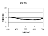
- FIG. 9 is a diagram showing the measurement results of the spectral reflectance of the decorative article produced in Example 1.
- FIG. FIG. 10 is a diagram schematically showing a decorative article produced in Example 2.
- FIG. 8 is a diagram schematically showing the ornament manufactured in Example 1.
- FIG. 9 is a diagram showing the measurement results of the spectral reflectance of the decorative article produced in Example 1.
- FIG. 11 is a diagram showing the measurement results of the spectral reflectance of the decorative article produced in Example 2.
- FIG. 12 is a diagram schematically showing a decorative article produced in Example 3.
- FIG. 13 is a diagram showing the measurement results of the spectral reflectance of the decorative article produced in Example 3.
- FIG. 14 is a diagram schematically showing a decorative article produced in Example 4.
- FIG. 15 is a diagram showing the measurement results of the spectral reflectance of the decorative article produced in Example 4.
- FIG. 16 is a diagram schematically showing a decorative article produced in Example 5.
- FIG. 17 is a diagram showing the measurement results of the spectral reflectance of the decorative article produced in Example 5.
- FIG. 18 is a diagram schematically showing the decorative article produced in Example 6.
- FIG. 19 is a diagram showing the measurement results of the spectral reflectance of the decorative article produced in Example 6.
- FIG. 20 is a diagram schematically showing the ornament manufactured in Comparative Example 1.
- FIG. 21 is a diagram showing the measurement results of the spectral reflectance of the decorative article produced in Comparative Example 1.
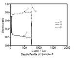
- FIG. 22 is a diagram showing the results of RBS measurement of the decorative article produced in Example 1.
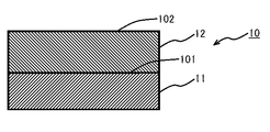
- the decorative article according to the present invention is a decorative article 10 having a base material 11 and a black hard film 12 made of diamond-like carbon (DLC) formed on the base material 11.
- DLC diamond-like carbon
- the base material used for this invention is a base material formed from a metal, ceramics, or a plastic.
- metals include stainless steel, titanium, titanium alloys, copper, copper alloys, tungsten, or hardened stainless steel, titanium, titanium alloys, and the like. These metals can be used alone or in combination of two or more. Moreover, it does not limit about the shape of the said base material.
- the black hard film is made of diamond-like carbon (DLC).
- DLC diamond-like carbon
- the film made of DLC is an amorphous film containing carbon and hydrogen and having an irregular mixture of carbon having sp 3 bonds corresponding to the diamond structure and carbon having sp 2 bonds corresponding to the graphite structure. It is.
- the hydrogen content at the surface 102 opposite to the substrate side in the black hard coating is larger than the hydrogen content at the substrate side surface 101 in the black hard coating (see FIG. 1).
- Specific examples include an aspect in which the hydrogen content increases as the distance from the substrate increases. For example, when the hydrogen content increases linearly or curvilinearly as the distance from the substrate increases, In some cases, it increases discontinuously (intermittently) like a stepped shape as the distance from the base material increases. Further, in the present invention, the hydrogen content on the surface of the black hard coating on the side opposite to the base material side is larger than the hydrogen content on the surface of the black hard coating on the side opposite to the base material side.
- the distance from the base material means “according to the thickness direction of the black hard coating perpendicular to the base material from the surface of the base material”.
- the region on the substrate side in the black hard coating has a small hydrogen content and high hardness, while the region on the side opposite to the substrate side in the black hard coating has a large hydrogen content and high decorativeness. It has a black color tone.
- the black hard film of the present invention since a region having a large hydrogen content is formed on a region having a small hydrogen content, both a black color tone and high hardness and scratch resistance can be achieved.
- the hydrogen content on the surface opposite to the substrate side in the black hard coating is 30.0 to 75.0 atm%, preferably 30.0 to 70.0 atm%.
- the hydrogen content on the surface opposite to the substrate is in the above range, a black color tone with high decorativeness can be obtained. That is, it is possible to satisfy the requirement that L * in the Lab color space display, which is an index of black color tone with high decorativeness, is 41 or less.
- the hydrogen content on the surface of the black hard coating on the base material side is smaller than the hydrogen content on the surface of the black hard coating on the side opposite to the base material side, and preferably 0-20. 0.0 atm%, more preferably 15.0 to 20.0 atm%.
- the thickness of the black hard coating is preferably 0.4 to 3.0 ⁇ m, more preferably 1.0 to 2.0 ⁇ m. When the thickness is in this range, a more preferable black color tone and higher hardness and scratch resistance can be achieved at the same time.
- the black hard coating preferably includes an inclined layer made of DLC.
- the hydrogen content in the graded layer increases (e.g., continuously) away from the substrate, and the hydrogen content on the surface of the graded layer opposite the substrate side is preferably 30.0. -75.0 atm%, more preferably 30.0-70.0 atm%.
- the hydrogen content on the substrate side surface in the inclined layer is preferably 0 to 20.0 atm%, more preferably 15.0 to 20.0 atm%. If the hydrogen content increases as the distance from the base material increases (for example, continuously), the interference fringes of the black hard coating become difficult to see and a favorable appearance is obtained. If no interference fringes are observed, the spectral reflectance at a wavelength of 350 to 750 nm is measured, and the variation in the value is small. For example, the difference between the maximum value and the minimum value of the spectral reflectance at a wavelength of 350 to 750 nm is 5. 0% or less.
- the thickness of the gradient layer is preferably 0.02 to 3.0 ⁇ m, more preferably 1.0 to 2.0 ⁇ m. When the thickness is within this range, the appearance of interference fringes can be further suppressed.
- the black hard coating further includes a low hydrogen content layer made of DLC formed on the substrate side with respect to the inclined layer.
- the hydrogen content in the low hydrogen content layer is preferably less than 30.0 atm%, more preferably 15.0 to 20.0 atm%.
- the hardness and scratch resistance of the entire black hard coating can be improved. Moreover, since the low hydrogen content layer absorbs light, the appearance of interference fringes is suppressed.
- the hydrogen content in the entire low hydrogen content layer is preferably smaller than the hydrogen content in the entire gradient layer.
- the thickness of the low hydrogen content layer is preferably 0.1 to 1.0 ⁇ m, more preferably 0.2 to 0.5 ⁇ m from the viewpoint of hardness and scratch resistance.
- the black hard coating preferably further includes an outermost surface layer made of DLC formed on the side opposite to the base material side with respect to the inclined layer.
- the hydrogen content in the outermost surface layer is preferably an amount of ⁇ 10.0 atm%, more preferably ⁇ 5.0 atm%, with respect to the hydrogen content on the surface opposite to the substrate side in the inclined layer. More preferably, it is the same amount as the hydrogen content on the surface of the gradient layer opposite to the substrate side.
- the hydrogen content in the outermost surface layer is preferably 30 to 75 atm%, more preferably 35 to 70 atm%.
- the thickness of the outermost surface layer is preferably 0.01 to 0.1 ⁇ m, more preferably 0.01 to 0.05 ⁇ m from the viewpoint of color tone.
- the layers made of DLC used in the present invention are F, Si, Ge, B, Al, Ti, V, Cr, Ni, Zr, Nb, Mo, Hf, It may further contain other elements such as T réelle and W.
- Other elements may be contained in a total amount of 5.0 to 40.0 atm% with respect to the total of 100.0 atm% of carbon, hydrogen, and other elements contained in the DLC layer.
- an adhesion layer may be formed between the base material and the black hard coating formed on the base material. Thereby, the adhesiveness of a base material and a black hard membrane
- the adhesion layer examples include a layer made of elements such as Si, Ge, Al, Ti, Cr, Zr, Nb, Mo, Hf, T réelle, and W, and a layer made of a compound containing these elements and carbon.
- the thickness of the adhesion layer is preferably 0.05 to 0.5 ⁇ m, more preferably 0.1 to 0.2 ⁇ m from the viewpoint of adhesion.
- the decorative article of the present invention has a base material and a black hard film made of DLC formed on the base material, and the hydrogen content on the surface of the base material side in the black hard film.
- the hydrogen content on the surface opposite to the substrate side in the black hard coating is larger, and the hydrogen content on the surface opposite to the substrate side in the black hard coating is 30.0 to 75.
- it will not specifically limit if it is 0.0 atm%, For example, the following aspects are mentioned.
- FIG. 1 As an aspect of the decorative product of the present invention, as shown in FIG. 1, there is a decorative product 10 in which a black hard coating 12 is formed on a substrate 11, and more specifically, hydrogen in a black hard coating.
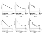
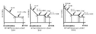
- a mode A in which the content continuously increases linearly with increasing distance from the base material is exemplified (see FIG. 5).
- the hydrogen content in the black hard film continuously increases in a curve as the distance from the base material increases
- aspect B the hydrogen content in the black hard film
- the amount increases discontinuously (intermittently) stepwise as the distance from the substrate increases (see FIG. 5).
- the region includes a region in which the hydrogen content decreases continuously or discontinuously (intermittently) as the distance from the substrate increases, and thereafter continuously or discontinuously (intermittently).
- C C ′ and D are also included (see FIG. 5).
- aspects A, A ′, C, and C ′ in aspects including aspects where the hydrogen content increases discontinuously (intermittently) as the distance from the substrate increases, and in aspects B and D, The aspect containing the area
- the hydrogen content is small on the substrate side in the black hard film, there is a region having a high hardness, the hydrogen content is large on the region, and there is a region having a black color tone, Both black color tone and high hardness and scratch resistance can be achieved.
- the low hydrogen content layer and the gradient layer As described above, by forming the low hydrogen content layer and the gradient layer, the hardness and scratch resistance of the entire black hard coating are brought about, and a black color tone without interference fringes is obtained. Furthermore, since the hydrogen content on the inclined layer side surface in the low hydrogen content layer and the hydrogen content on the low hydrogen content layer side in the inclined layer are the same amount, the appearance of interference fringes is more likely. It is suppressed and a preferable appearance is obtained.
- the hydrogen content of the low hydrogen content layer is preferably less than 30.0 atm%, more preferably 15.0 to 20.0 atm%, from the viewpoints of hardness and scratch resistance.
- the hydrogen content of the gradient layer increases from the hydrogen content at the surface of the gradient layer side in the low hydrogen content layer to 30.0-75.0 atm% as the distance from the substrate increases from the viewpoint of color tone. It is preferable to increase to 30.0 to 70.0 atm%, and more preferable.
- the thickness of the low hydrogen content layer is preferably 0.2 to 1.0 ⁇ m, more preferably 0.4 to 0.6 ⁇ m from the viewpoint of hardness and scratch resistance.
- the thickness of the inclined layer is preferably 0.01 to 0.5 ⁇ m, more preferably 0.02 to 0.2 ⁇ m, from the viewpoint of color tone.
- the black hard coating 32 on the base material 31 includes the first low hydrogen content layer 33 and the second low hydrogen content layer as the low hydrogen content layer.
- a decorative product 30 that includes a quantitative layer 34 and further includes an intermediate layer 35 made of DLC is also included (Aspect F).
- the first low hydrogen content layer 33, the intermediate layer 35, the second low hydrogen content layer 34, and the inclined layer 36 are formed in this order from the base material 31 side, and the first low hydrogen content layer 33 is formed in this order.
- the hydrogen content in the hydrogen content layer is smaller than the hydrogen content in the second low hydrogen content layer
- the hydrogen content in the intermediate layer and the hydrogen content in the gradient layer move away from the substrate ( For example, continuously (see FIG. 6).
- the hydrogen content on the surface 301 on the intermediate layer side in the first low hydrogen content layer is the same as the hydrogen content on the surface 302 on the first low hydrogen content layer side in the intermediate layer.
- the hydrogen content at the surface 303 on the second low hydrogen content layer side in the intermediate layer is the same as the hydrogen content at the surface 304 on the intermediate layer side in the second low hydrogen content layer.
- the hydrogen content at the surface 305 on the gradient layer side in the second low hydrogen content layer and the hydrogen content at the surface 306 on the second low hydrogen content layer side in the gradient layer are the same amount. is there.
- the low hydrogen content layer and the gradient layer As described above, by forming the low hydrogen content layer and the gradient layer, the hardness and scratch resistance of the entire black hard coating are brought about, and a black color tone without interference fringes is obtained. Furthermore, since the first low hydrogen content layer, which has a lower hydrogen content than the second low hydrogen content layer, absorbs light more, the appearance of interference fringes is further suppressed, and the first low hydrogen content layer Since the second low hydrogen content layer having a higher hydrogen content than the layer has a higher hardness, the hardness and scratch resistance of the entire black hard coating can be further improved. Further, since the hydrogen content at the boundary of each layer is the same amount, the appearance of interference fringes is further suppressed and a preferable appearance is obtained.
- the hydrogen content of the first low hydrogen content layer is preferably less than 21.0 atm%, more preferably 10.0 to 20.0 atm%, from the viewpoint of suppressing interference fringes
- the hydrogen content of the low hydrogen content layer is larger than the hydrogen content in the first low hydrogen content layer, and preferably 21.0 atm% or more and less than 30.0 atm% from the viewpoint of hardness and scratch resistance. More preferably, it is 21.0 to 25.0 atm%.
- the hydrogen content of the intermediate layer increases from the hydrogen content in the first low hydrogen content layer to the hydrogen content in the second low hydrogen content layer as the distance from the base material increases. .
- the hydrogen content of the gradient layer is 30.0 to 75.0 atm from the hydrogen content on the gradient layer side surface in the second low hydrogen content layer as the distance from the substrate increases from the viewpoint of color tone.
- % Is preferable, and it is more preferable to increase to 30.0 to 70.0 atm%.
- the thickness of the first low hydrogen content layer is preferably 0.1 to 0.7 ⁇ m, more preferably 0.2 to 0.3 ⁇ m, from the viewpoint of suppressing interference fringes, and the second
- the thickness of the low hydrogen content layer is preferably 0.1 to 0.5 ⁇ m, more preferably 0.2 to 0.3 ⁇ m from the viewpoint of hardness and scratch resistance.
- the thickness of the intermediate layer is preferably 0.05 to 0.5 ⁇ m, more preferably 0.1 to 0.2 ⁇ m from the viewpoint of suppressing interference fringes, and the thickness of the inclined layer is preferably from the viewpoint of color tone. Therefore, the thickness is preferably 0.01 to 0.5 ⁇ m, more preferably 0.02 to 0.2 ⁇ m.
- the black hard film 32 is the outermost surface made of DLC formed on the side opposite to the substrate side with respect to the inclined layer.
- the aspect which further contains the layer 37 is also mentioned (aspect G).
- the hydrogen content in the outermost surface layer is preferably an amount of ⁇ 10.0 atm%, more preferably ⁇ 5.0 atm with respect to the hydrogen content on the surface 307 opposite to the substrate side in the inclined layer. %, And more preferably the same amount as the hydrogen content on the surface 307 opposite to the substrate side in the gradient layer.
- FIG. 6 shows a case where the hydrogen content in the outermost surface layer is the same as the hydrogen content on the surface 307 opposite to the substrate side in the inclined layer.
- the thickness of the outermost surface layer is preferably 0.01 to 0.1 ⁇ m, more preferably 0.01 to 0.05 ⁇ m from the viewpoint of color tone.
- the hydrogen content increases linearly as the distance from the base material increases.
- Linear regions and curved regions may be combined, or linear regions with different gradients may be combined.
- the hydrogen content in the inclined layers of the above embodiments E to G is specifically the straight line connecting the point B and the point C rather than the absolute value of the inclination of the straight line connecting the point A and the point B shown in FIG.
- the absolute value of the slope of is increased so as to be larger.
- point A is the hydrogen content on the substrate surface
- point B is the hydrogen content on the substrate side surface of the gradient layer
- point C is the surface of the gradient layer opposite to the substrate. Represents the hydrogen content.
- adherence layer is formed between the base material and the black hard film with respect to the aspect mentioned above is mentioned.
- the film hardness of the decorative article of the present invention described above is usually HV1000 or more, preferably HV1200 to 1800, and has excellent scratch resistance.
- the method for manufacturing a decorative article of the present invention is the above-described method for manufacturing a decorative article. That is, a method for manufacturing a decorative article having a base material and a black hard film made of diamond-like carbon formed on the base material, including a black hard film forming step of forming a black hard film by a plasma CVD method .
- a black hard film forming step of forming a black hard film by a plasma CVD method a black hard film forming step of forming a black hard film by a plasma CVD method .
- the hydrogen content on the surface opposite to the substrate side in the black hard film is larger than the hydrogen content on the substrate side surface in the black hard film.
- the black hard coating is formed so that the hydrogen content on the surface opposite to the substrate side in the coating is 30.0-75.0 atm%.
- a negative voltage is applied to the base material set in the vacuum apparatus, and the gas containing the raw material is plasmatized and chemically reacted, and then adsorbed onto the base material. Form a film.
- the gas containing the raw material hydrocarbon gas such as methane, acetylene and benzene is preferably used.
- membrane which consists of DLC containing carbon and hydrogen can be formed.
- the voltage applied to the substrate is usually 100.0 V to 5.0 kV.
- the relationship between the voltage applied to the substrate and the hydrogen content is determined in advance, and in the case of an actual black hard film, a method of controlling only the voltage is preferable. Used for.
- the thickness a method in which the film formation rate per unit time is obtained in advance and only the film formation time is controlled in the case of an actual black hard film is preferably used.
- the hydrogen content and thickness in the actual black hard coating can be determined by resonance nuclear reaction (NRA) and Rutherford backscattering spectroscopy (RBS).
- a chemical vapor deposition method such as a sputtering method, an arc method or an ion plating method, a chemical vapor deposition method such as an ionization vapor deposition method or an RF plasma CVD method is used.
- a phase growth method (CVD) is preferably used.
- an organic silicon compound gas such as tetramethylsilane is mixed with a hydrocarbon gas such as methane, acetylene, or benzene. Then, the mixture gas is introduced into a vacuum apparatus, the mixed gas is converted into plasma using an ion source, and a negative voltage is applied to the base material to form DLC containing Si on the base material surface.
- a hydrocarbon gas such as methane, acetylene, or benzene.
- a DLC is formed on the substrate surface by ionizing a hydrocarbon gas such as methane, acetylene or benzene. Then, Cr is sputtered by a DC sputtering method to include Cr in the DLC film.
- Cr may be evaporated by an arc method or an ion plating method and included in the DLC film. In this method, other elements such as F, Si, Ge, B, Al, Ti, V, Ni, Zr, Nb, Mo, Hf, Ta, and W are included by changing the solid material into another solid. DLC can be formed.
- a contact layer formation process is performed, and then the above-mentioned base material on which the contact layer is formed.
- a black hard film formation process is performed.
- the adhesion layer forming step is a step of forming an adhesion layer on the substrate by a wet plating method or a dry plating method.
- the dry plating method include a sputtering method, an arc method, an ion plating method, a physical vapor deposition method (PVD) such as an ion beam, and CVD.
- the sputtering method, the arc method, and the ion plating method are preferably used.
- Examples of the decorative article of the present invention include a watch, a necklace, a pendant, a brooch, and glasses. These may be partly composed of the above-mentioned ornamental product, or may be entirely composed of the above-mentioned ornamental product.
- the watch may be any of a photovoltaic watch, a thermoelectric watch, a radio wave reception type self-correcting watch, a mechanical watch, and a general electronic watch.
- a timepiece is manufactured by a known method using the decorative article.
- a wristwatch is an example of a decorative article that is easily damaged by rubbing with a shirt or colliding with a desk or wall.
- the present invention relates to the following (1) to (8), for example.
- a decorative article having a base material and a black hard film made of diamond-like carbon formed on the base material,
- the hydrogen content on the surface opposite to the substrate side in the black hard coating is larger than the hydrogen content on the substrate side surface in the black hard coating, and the black hard coating
- a decorative article characterized in that the hydrogen content on the surface opposite to the substrate side is 30.0 to 75.0 atm%. According to such a decorative article, both black color tone and high hardness and scratch resistance can be achieved.
- the black hard coating includes an inclined layer made of diamond-like carbon,
- the hydrogen content in the graded layer increases (e.g., continuously) away from the substrate;
- Such a decorative article has a preferable appearance because the interference fringes of the black hard film are hardly seen.
- the black hard coating further includes a low hydrogen content layer made of diamond-like carbon formed on the substrate side with respect to the inclined layer,
- Such a decorative article has high hardness and scratch resistance of the entire black hard film, and interference fringes are hardly seen.
- the black hard coating layer includes a first low hydrogen content layer and a second low hydrogen content layer as the low hydrogen content layer, and further includes an intermediate layer made of diamond-like carbon, From the base material side, the first low hydrogen content layer, the intermediate layer, the second low hydrogen content layer and the inclined layer are formed in this order, The hydrogen content in the first low hydrogen content layer is smaller than the hydrogen content in the second low hydrogen content layer, The hydrogen content in the intermediate layer increases as it moves away from the substrate (eg continuously), The hydrogen content on the surface on the intermediate layer side in the first low hydrogen content layer is the same amount as the hydrogen content on the surface on the first low hydrogen content layer side in the intermediate layer.
- the hydrogen content at the surface on the second low hydrogen content layer side in the intermediate layer and the hydrogen content at the surface on the intermediate layer side in the second low hydrogen content layer are the same amount.
- the hydrogen content on the surface of the gradient layer side in the second low hydrogen content layer and the hydrogen content on the surface of the gradient layer on the second low hydrogen content layer side are the same amount.
- the ornament according to (3) which is characterized in that The ornaments of the above (4) and (5) have higher hardness and scratch resistance of the entire black hard film, and interference fringes are less likely to be seen.
- the black hard coating further includes an outermost surface layer made of diamond-like carbon formed on the side opposite to the base material side with respect to the inclined layer,
- the hydrogen content in the outermost surface layer is an amount of ⁇ 10.0 atm% with respect to the hydrogen content on the surface of the gradient layer on the side opposite to the substrate side (2) to (5)
- a method for producing a decorative article having a base material and a black hard film made of diamond-like carbon formed on the base material Including a black hard film forming step of forming the black hard film by a plasma CVD method, In the black hard coating forming step, the hydrogen content on the surface opposite to the substrate side in the black hard coating is more than the hydrogen content on the substrate side surface in the black hard coating.
- the film hardness was measured using a micro indentation hardness tester (H100 manufactured by FISCHER). A Vickers indenter was used as a measuring element. After holding at 5 mN load for 10 seconds, unloading was performed, and the film hardness was calculated from the depth of the inserted Vickers indenter.
- a black hard film was formed by controlling the bias, and it was considered that a film having a desired hydrogen content was formed.
- a film was formed on the base material for a certain time under arbitrary constant conditions, and the film thickness of the formed film was measured. Specifically, a film is formed by attaching a mask to a part of the surface of the Si base material, and the mask is removed after the film formation, so that a step between the mask area where no film is attached and the non-mask area where the film is attached was measured to measure the film thickness.
- a stylus type surface profile measuring device Dektak 6M manufactured by ULVAC was used for this step measurement.
- a film formation rate per unit time was obtained by dividing the obtained film thickness by the film formation time. In Examples and Comparative Examples, it was considered that a film having a desired film thickness was formed by forming the black hard film by controlling the film formation time using the film formation speed.
- Example 1 As a first treatment, clean substrates (Si substrate and SUS substrate) were placed in a vacuum device, and the inside of the device was evacuated while heating the flat plate to 120 ° C. by a heater installed inside the device.
- acetylene gas is introduced as a raw material gas, and after maintaining the apparatus pressure at 1.0 Pa, the acetylene gas is decomposed by a plasma CVD method.
- a DLC layer was formed on the substrate.
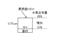
- the negative voltage applied to the base material was intermittently lowered from 3 kV to 100 V from the initial stage of film formation to the end of film formation. Further, the film formation time was adjusted so that the thickness of the DLC layer was 0.75 ⁇ m.
- Example 2 First, the same treatment as the first treatment in Example 1 is performed, and then, in addition to Ar gas as an inert gas, acetylene gas is introduced as a raw material gas into the vacuum device, and the pressure in the device is maintained at 1.0 Pa. After that, acetylene gas was decomposed by a plasma CVD method to form a DLC layer on the substrate. In forming the DLC layer, a 0.6 ⁇ m layer was first formed at a bias of 3 kV, and then the voltage was continuously lowered from a bias of 3 kV to 100 V to form a 0.2 ⁇ m thick gradient layer. After these DLC layers were formed, the introduction of acetylene gas and Ar gas into the vacuum apparatus was stopped, cooling was performed while maintaining the vacuum in the vacuum apparatus, and then the atmosphere was released and the substrate was taken out.
- Ar gas as an inert gas
- Example 3 First, the same treatment as the first treatment in Example 1 is performed, and then, in addition to Ar gas as an inert gas, acetylene gas is introduced as a raw material gas into the vacuum device, and the pressure in the device is maintained at 1.0 Pa. After that, acetylene gas was decomposed by a plasma CVD method to form a DLC layer on the substrate.
- a plasma CVD method to form a DLC layer on the substrate.
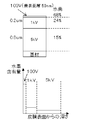
- a 0.4 ⁇ m layer is formed at a bias of 3 kV, then the voltage is continuously stepped down from a bias of 3 kV to 1 kV to form an intermediate layer of a film thickness of 0.1 ⁇ m, and then a bias of 1 kV.
- the measurement results of the spectral reflectance in FIG. 13 shows the hardness of the black hard coating, ornaments L * of the measurement results in Table 1.
- Example 4 First, the same treatment as the first treatment in Example 1 is performed, and then, in addition to Ar gas as an inert gas, acetylene gas is introduced as a raw material gas into the vacuum device, and the pressure in the device is maintained at 1.0 Pa. After that, acetylene gas was decomposed by a plasma CVD method to form a DLC layer on the substrate.
- a 0.1 ⁇ m layer is formed at a bias of 5 kV, then the voltage is continuously stepped down from a bias of 5 kV to 1 kV to form an intermediate layer of a film thickness of 0.1 ⁇ m, and then a bias is formed.
- a 0.2 ⁇ m layer was formed at 1 kV, and finally the voltage was continuously stepped down from a bias of 1 kV to 100 V to form an inclined layer having a thickness of 0.02 ⁇ m.
- the introduction of acetylene gas and Ar gas into the vacuum apparatus was stopped, cooling was performed while maintaining the vacuum in the vacuum apparatus, and then the atmosphere was released and the substrate was taken out.
- a decorative article having a configuration of hydrogen content increase from 24.0 atm% to 68.0 atm% as the distance from the base material increases was produced.
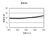
- the measurement result of the spectral reflectance is shown in FIG. 15, and the measurement result of the hardness of the black hard film and the L * of the decorative article is shown in Table 1.
- Example 5 First, the same treatment as the first treatment in Example 1 is performed, and then, in addition to Ar gas as an inert gas, acetylene gas is introduced as a raw material gas into the vacuum device, and the pressure in the device is maintained at 1.0 Pa. After that, acetylene gas was decomposed by a plasma CVD method to form a DLC layer on the substrate. In forming the DLC layer, first, a 0.7 ⁇ m layer is formed at a bias of 5 kV, then the voltage is continuously stepped down from a bias of 5 kV to 1 kV to form an intermediate layer of a film thickness of 0.1 ⁇ m, and then a bias is formed.
- a 0.2 ⁇ m layer was formed at 1 kV, and then the voltage was continuously lowered from a bias of 1 kV to 100 V to form a 0.03 ⁇ m thick layer, and finally, a 50 nm thick layer was formed at a bias of 100 V.
- the introduction of acetylene gas and Ar gas into the vacuum apparatus was stopped, cooling was performed while maintaining the vacuum in the vacuum apparatus, and then the atmosphere was released and the substrate was taken out.
- FIG. 17 shows the measurement results of the spectral reflectance
- Table 1 shows the measurement results of the hardness of the black hard coating and the L * of the decorative product.
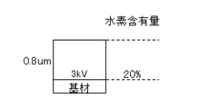
- Example 6 First, the same treatment as the first treatment in Example 1 is performed, and then, in addition to Ar gas as an inert gas, acetylene gas is introduced as a raw material gas into the vacuum device, and the pressure in the device is maintained at 1.0 Pa. After that, acetylene gas was decomposed by a plasma CVD method to form a DLC layer on the substrate. In forming the DLC layer, a 0.8 ⁇ m layer was first formed with a bias of 5 kV, then a 0.2 ⁇ m layer was formed with a bias of 1 kV, and finally a layer with a thickness of 50 nm was formed with a bias of 100 V. After these DLC layers were formed, the introduction of acetylene gas and Ar gas into the vacuum apparatus was stopped, cooling was performed while maintaining the vacuum in the vacuum apparatus, and then the atmosphere was released and the substrate was taken out.
- Ar gas as an inert gas
- the measurement result of the spectral reflectance is shown in FIG. 19, and the measurement result of the hardness of the black hard film and the L * of the decorative article is shown in Table 1.
- Example 1 First, the same treatment as the first treatment in Example 1 is performed, and then, in addition to Ar gas as an inert gas, acetylene gas is introduced as a raw material gas into the vacuum device, and the pressure in the device is maintained at 1.0 Pa. After that, acetylene gas was decomposed by a plasma CVD method, and a bias of 3 kV was applied to the substrate to form a DLC layer having a thickness of 0.8 ⁇ m. After the DLC layer was formed, the introduction of acetylene gas and Ar gas into the vacuum apparatus was stopped, cooling was performed while maintaining the vacuum in the vacuum apparatus, and then the atmosphere was released to take out the substrate.
- Ar gas as an inert gas
- Example 1 to 5 and Comparative Example 1 no interference color was observed, but in Example 6, an interference color was observed.
- black hard coatings were prepared using ⁇ relationship between bias and hydrogen content> and ⁇ relationship between coating formation time and film thickness> obtained in advance.
- the hydrogen content and thickness of the black hard film actually produced were measured by RBS measurement (FIG. 22). This measured value satisfied the above ⁇ Relationship between bias and hydrogen content> and ⁇ Relationship between film formation time and film thickness>.
- Si indicated by a dotted line is a base material, and the amount of carbon indicated by an alternate long and short dash line decreases and the amount of hydrogen indicated by a solid line increases from the surface of the base material corresponding to the decrease in bias. ing.
Landscapes
- Chemical & Material Sciences (AREA)
- Engineering & Computer Science (AREA)
- General Chemical & Material Sciences (AREA)
- Chemical Kinetics & Catalysis (AREA)
- Materials Engineering (AREA)
- Mechanical Engineering (AREA)
- Metallurgy (AREA)
- Organic Chemistry (AREA)
- Physics & Mathematics (AREA)
- Plasma & Fusion (AREA)
- Inorganic Chemistry (AREA)
- Chemical Vapour Deposition (AREA)
- Adornments (AREA)
- Laminated Bodies (AREA)
- Carbon And Carbon Compounds (AREA)
- Physical Vapour Deposition (AREA)
Abstract
Description
表面処理技術を用いた黒色皮膜の一例として、湿式メッキ法を用いたニッケル・リン合金皮膜が挙げられる(特許文献1参照)。しかしながら、皮膜自体が軟質であるため、前述の傷等による外観品質の低下を解決するには至らない。
<装飾品>
本発明に係る装飾品は、図1に示すように、基材11と、該基材11上に形成されたダイヤモンドライクカーボン(DLC)からなる黒色硬質皮膜12とを有する装飾品10である。
本発明に用いる基材は、金属、セラミックスまたはプラスチックから形成される基材である。金属(合金を含む)として、具体的にはステンレス鋼、チタン、チタン合金、銅、銅合金、タングステン、または硬質化処理したステンレス鋼、チタン、チタン合金などが挙げられる。これらの金属は、1種単独でまたは2種以上組み合わせて用いることができる。また、上記基材の形状については限定されない。
黒色硬質皮膜は、ダイヤモンドライクカーボン(DLC)からなる。このDLCからなる皮膜は、炭素と水素とを含み、ダイヤモンド構造に対応するsp3結合を有する炭素と、グラファイト構造に対応するsp2結合を有する炭素とが不規則に混在する非晶質の膜である。
上記黒色硬質皮膜は、DLCからなる傾斜層を含むことが好ましい。この傾斜層中の水素含有量は基材から離れるにしたがって(たとえば連続的に)増加しており、傾斜層における基材側とは反対側の表面での水素含有量は、好ましくは30.0~75.0atm%、より好ましくは30.0~70.0atm%である。
水素含有量が基材から離れるにしたがって(たとえば連続的に)増加していると、黒色硬質皮膜の干渉縞が見られにくくなり、好ましい外観となる。なお、干渉縞が見られない場合は、波長350~750nmにおける分光反射率を測定すると、値のばらつきが小さく、たとえば波長350~750nmにおける分光反射率の最大値と最小値との差は5.0%以下となる。
傾斜層の厚さは、好ましくは0.02~3.0μm、より好ましくは1.0~2.0μmである。厚さがこの範囲にあると、干渉縞の出現をより抑え得る。
上記黒色硬質皮膜は、傾斜層よりも基材側に形成されたDLCからなる低水素含有量層をさらに含むことが好ましい。この低水素含有量層中の水素含有量は、好ましくは30.0atm%未満、より好ましくは15.0~20.0atm%である。
低水素含有量層の厚さは、硬度および耐傷性の観点から、好ましくは0.1~1.0μm、より好ましくは0.2~0.5μmである。
上記黒色硬質皮膜は、傾斜層に対して基材側とは反対側に形成されたDLCからなる最表面層をさらに含むことが好ましい。最表面層中の水素含有量は、傾斜層における基材側とは反対側の表面での水素含有量に対して好ましくは±10.0atm%の量であり、より好ましくは±5.0atm%の量であり、さらに好ましくは傾斜層における基材側とは反対側の表面での水素含有量と同じ量である。また、最表面層中の水素含有量は、好ましくは30~75atm%、より好ましくは35~70atm%である。
最表面層の厚さは、色調の観点から、好ましくは0.01~0.1μm、より好ましくは0.01~0.05μmである。
本発明に用いるDLCからなる層、すなわち傾斜層、低水素含有量層、最表面層は、F、Si、Ge、B、Al、Ti、V、Cr、Ni、Zr、Nb、Mo、Hf、Tа、Wなどのその他の元素をさらに含んでいてもよい。その他の元素は合計で、DLCからなる層に含まれる炭素、水素、およびその他の元素の合計100.0atm%に対して、5.0~40.0atm%含まれていてもよい。その他の元素が含まれていると、硬度の上昇、各層と基材との密着性向上、摩擦係数の低下、耐熱性の向上、耐摩耗性の向上、撥水性の向上、および電気抵抗の低下などの効果が見込まれる。
本発明の装飾品においては、基材と、該基材上に形成された上記黒色硬質皮膜との間に、密着層が形成されていてもよい。これにより、基材と黒色硬質皮膜との密着性を高めることができる。
密着層の厚さは、密着性の観点から、好ましくは0.05~0.5μm、より好ましくは0.1~0.2μmである。
本発明の装飾品としては、上記のように、基材と、基材上に形成されたDLCからなる黒色硬質皮膜を有しており、黒色硬質皮膜における基材側の表面での水素含有量よりも、黒色硬質皮膜における基材側とは反対側の表面での水素含有量の方が大きく、黒色硬質皮膜における基材側とは反対側の表面での水素含有量が30.0~75.0atm%であれば、特に限定されないが、たとえば以下のような態様が挙げられる。
本発明の装飾品の態様としては、図1に示すように、基材11上に黒色硬質皮膜12が形成された装飾品10が挙げられるが、さらに具体的には、黒色硬質皮膜中の水素含有量が基材から離れるにしたがって連続的に直線的に増加している態様Aが挙げられる(図5参照)。また、態様A'のように、黒色硬質皮膜中の水素含有量が基材から離れるにしたがって連続的に曲線的に増加している態様や、態様Bのように、黒色硬質皮膜中の水素含有量が基材から離れるにしたがって不連続的(間欠的)に階段状に増加している態様も挙げられる(図5参照)。また、態様A、A'、Bに対して、基材から離れるにしたがって水素含有量が連続的または不連続的(間欠的)に減少する領域を含み、その後連続的または不連続的(間欠的)に増加している態様C、C'、Dも挙げられる(図5参照)。
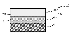
本発明の装飾品の態様としては、図2に示すように、基材21側から黒色硬質皮膜22として低水素含有量層23および傾斜層26がこの順で形成されている装飾品20も挙げられる(態様E)。この態様Eでは、傾斜層26中の水素含有量が基材から離れるにしたがって(たとえば連続的に)増加しており、低水素含有量層における傾斜層側の表面201での水素含有量と、傾斜層における低水素含有量層側の表面202での水素含有量とが同じ量である(図6参照)。
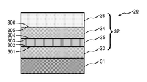
本発明の装飾品の態様としては、図3に示すように、基材31上の黒色硬質皮膜32が、低水素含有量層として第一の低水素含有量層33および第二の低水素含有量層34を含むとともに、DLCからなる中間層35をさらに含む装飾品30も挙げられる(態様F)。この態様Fでは、基材31側から第一の低水素含有量層33、中間層35、第二の低水素含有量層34および傾斜層36がこの順で形成されており、第一の低水素含有量層中の水素含有量が第二の低水素含有量層中の水素含有量よりも小さく、中間層中の水素含有量および傾斜層中の水素含有量が基材から離れるにしたがって(たとえば連続的に)増加している(図6参照)。この態様Fでは、第一の低水素含有量層における中間層側の表面301での水素含有量と、中間層における第一の低水素含有量層側の表面302での水素含有量とが同じ量であり、中間層における第二の低水素含有量層側の表面303での水素含有量と、第二の低水素含有量層における中間層側の表面304での水素含有量とが同じ量であり、第二の低水素含有量層における傾斜層側の表面305での水素含有量と、傾斜層における第二の低水素含有量層側の表面306での水素含有量とが同じ量である。
本発明の装飾品の態様としては、図4に示すように、態様Fに対して、黒色硬質皮膜32が、傾斜層に対して基材側とは反対側に形成されたDLCからなる最表面層37をさらに含む態様も挙げられる(態様G)。最表面層中の水素含有量は、傾斜層における基材側とは反対側の表面307での水素含有量に対して好ましくは±10.0atm%の量であり、より好ましくは±5.0atm%の量であり、さらに好ましくは傾斜層における基材側とは反対側の表面307での水素含有量と同じ量である。なお、図6では、最表面層中の水素含有量が、傾斜層における基材側とは反対側の表面307での水素含有量と同じ量である場合を示している。
態様Gにおいては、最表面層の厚さは、色調の観点から、好ましくは0.01~0.1μm、より好ましくは0.01~0.05μmである。
上述した態様に対して、基材と黒色硬質皮膜との間に密着層が形成されている態様が挙げられる。
上述した本発明の装飾品の膜硬度は、通常HV1000以上、好ましくはHV1200~1800であり、耐傷性に優れる。
本発明の装飾品の製造方法は、上述した装飾品の製造方法である。すなわち、基材と、基材上に形成されたダイヤモンドライクカーボンからなる黒色硬質皮膜とを有する装飾品の製造方法であって、プラズマCVD法により黒色硬質皮膜を形成する黒色硬質皮膜形成工程を含む。この黒色硬質皮膜形成工程では、黒色硬質皮膜における基材側の表面での水素含有量よりも、黒色硬質皮膜における基材側とは反対側の表面での水素含有量の方が大きく、黒色硬質皮膜における基材側とは反対側の表面での水素含有量が30.0~75.0atm%となるように、黒色硬質皮膜を形成する。
基材に印加する電圧は、通常100.0V~5.0kVである。皮膜形成開始からの時間に対して適宜電圧を設定することにより、黒色硬質皮膜における水素含有量を上記範囲にコントロールできる。たとえば、上述した傾斜層、中間層については、具体的には層の形成中に電圧を適宜小さくしていくことで、層中での水素含有量を増加させられる。
本発明の装飾品としては、時計、ネックレス、ペンダント、ブローチ、眼鏡などが挙げられる。これらは、一部が上記装飾品で構成されていても、全部が上記装飾品で構成されていてもよい。
(1) 基材と、上記基材上に形成されたダイヤモンドライクカーボンからなる黒色硬質皮膜とを有する装飾品であって、
上記黒色硬質皮膜における上記基材側の表面での水素含有量よりも、上記黒色硬質皮膜における上記基材側とは反対側の表面での水素含有量の方が大きく、上記黒色硬質皮膜における上記基材側とは反対側の表面での水素含有量が30.0~75.0atm%であることを特徴とする装飾品。
このような装飾品によれば、黒色色調と、高い硬度および耐傷性とが両立できる。
上記傾斜層中の水素含有量が上記基材から離れるにしたがって(たとえば連続的に)増加しており、
上記傾斜層における上記基材側とは反対側の表面での水素含有量が30.0~75.0atm%であることを特徴とする(1)に記載の装飾品。
このような装飾品は、黒色硬質皮膜の干渉縞が見られにくく、好ましい外観を有する。
上記低水素含有量層中の水素含有量が30.0atm%未満であることを特徴とする(2)に記載の装飾品。
このような装飾品は、黒色硬質皮膜全体の硬度および耐傷性も高く、干渉縞が見られにくい。
上記基材側から、上記第一の低水素含有量層、上記中間層、上記第二の低水素含有量層および上記傾斜層がこの順で形成されており、
上記第一の低水素含有量層中の水素含有量が上記第二の低水素含有量層中の水素含有量よりも小さく、
上記中間層中の水素含有量が上記基材から離れるにしたがって(たとえば連続的に)増加しており、
上記第一の低水素含有量層における上記中間層側の表面での水素含有量と、上記中間層における上記第一の低水素含有量層側の表面での水素含有量とが同じ量であり、上記中間層における上記第二の低水素含有量層側の表面での水素含有量と、上記第二の低水素含有量層における上記中間層側の表面での水素含有量とが同じ量であり、上記第二の低水素含有量層における上記傾斜層側の表面での水素含有量と、上記傾斜層における上記第二の低水素含有量層側の表面での水素含有量とが同じ量であることを特徴とする(3)に記載の装飾品。
上記(4)、(5)の装飾品は、黒色硬質皮膜全体の硬度および耐傷性もより高く、干渉縞がより見られにくい。
上記最表面層中の水素含有量が上記傾斜層における上記基材側とは反対側の表面での水素含有量に対して±10.0atm%の量であることを特徴とする(2)~(5)のいずれかに記載の装飾品。
このような装飾品によれば、より装飾性が高い黒色色調が得られる。
このような装飾品によれば、黒色色調と、高い硬度および耐傷性とが両立できる。
プラズマCVD法により上記黒色硬質皮膜を形成する黒色硬質皮膜形成工程を含み、
上記黒色硬質被膜形成工程は、上記黒色硬質皮膜における上記基材側の表面での水素含有量よりも、上記黒色硬質皮膜における上記基材側とは反対側の表面での水素含有量の方が大きく、上記黒色硬質皮膜における上記基材側とは反対側の表面での水素含有量が30.0~75.0atm%となるように、上記黒色硬質皮膜を形成することを特徴とする装飾品の製造方法。
このような装飾品の製造方法によれば、上述したような黒色色調と、高い硬度および耐傷性とが両立された装飾品が得られる。
以下、実施例に基づいて本発明をさらに具体的に説明するが、本発明はこれらの実施例に限定されるものではない。
〔分光反射率およびL*〕
分光反射率およびL*はコニカミノルタ社製の分光測色計CM-2600dで測定した。
膜硬度は、微小押込み硬さ試験機(FISCHER製H100)を用いて行った。測定子にはビッカース圧子を使用し、5mN荷重で10秒間保持した後に除荷を行い、挿入されたビッカース圧子の深さから膜硬度を算出した。
National Electrostatics Corporation製Pelletron 3SDHによって測定した。
Radiation Dynamics,Inc.製RPEA 4.0 Dynamitronによって測定した。
CVD法の一つであるところのイオン化蒸着法によって基材表面にDLCを形成する際、基材印加したバイアスを段階的に変化させた。このようにして得られた皮膜の水素含有量の膜厚方向変化をNRAによって分析し、バイアスと水素含有量の関係を得た(図7)。
基材に任意の一定条件で一定時間皮膜を形成し、形成された皮膜の膜厚を測定した。具体的には、Si基材表面の一部の領域にマスクを付けて成膜し、成膜後にマスクを外し、膜の付着していないマスク領域と、膜の付着した非マスク領域との段差を計測して膜厚を測定した。この段差測定にはULVAC社製触針式表面形状測定器Dektak6Mを使用した。得られた膜厚を成膜時間で除算する事によって、単位時間当たりの成膜速度を得た。
実施例、比較例においては、上記成膜速度を用い、成膜時間をコントロールして黒色硬質皮膜を形成し、所望の膜厚を有する皮膜が形成されているとみなした。
第一処理として、清浄な基材(Si基板およびSUS基板)を真空装置内に配置し、装置内部に設置したヒーターによって平板を120℃に加熱しながら装置内を真空排気した。
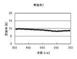
このようにして、図8に模式的に示すような基材/0.75μmの黒色硬質皮膜(水素含有量=基材から離れるにしたがって20.0atm%~68.0atm%に階段状に増加)の構成を有する装飾品を作製した。分光反射率の測定結果を図9に、黒色硬質皮膜の硬度、装飾品のL*の測定結果を表1に示す。
まず、実施例1の第一処理と同様の処理を行い、次に真空装置内に不活性ガスとしてのArガスに加え、原料ガスとしてアセチレンガスを導入し、装置内圧力を1.0Paに保った上でプラズマCVD法によりアセチレンガスを分解し、基材上にDLC層を形成した。DLC層を形成するにあたっては、まずバイアス3kVで0.6μmの層を形成し、次にバイアス3kVから100Vへと連続的に降圧し、膜厚0.2μmの傾斜層を形成した。これらのDLC層が形成された後に、真空装置内へのアセチレンガス及びArガスの導入を停止し、真空装置内の真空を保ったまま冷却を行い、その後大気開放し基材を取り出した。
まず、実施例1の第一処理と同様の処理を行い、次に真空装置内に不活性ガスとしてのArガスに加え、原料ガスとしてアセチレンガスを導入し、装置内圧力を1.0Paに保った上でプラズマCVD法によりアセチレンガスを分解し、基材上にDLC層を形成した。DLC層を形成するにあたっては、まずバイアス3kVで0.4μmの層を形成し、次にバイアス3kVから1kVへと連続的に降圧し、膜厚0.1μmの中間層を形成、次にバイアス1kVで0.5μmの層を形成し、最後にバイアス1kVから100Vへと連続的に降圧し、膜厚0.1μmの傾斜層を形成した。これらのDLC層が形成された後に、真空装置内へのアセチレンガス及びArガスの導入を停止し、真空装置内の真空を保ったまま冷却を行い、その後大気開放し基材を取り出した。
まず、実施例1の第一処理と同様の処理を行い、次に真空装置内に不活性ガスとしてのArガスに加え、原料ガスとしてアセチレンガスを導入し、装置内圧力を1.0Paに保った上でプラズマCVD法によりアセチレンガスを分解し、基材上にDLC層を形成した。DLC層を形成するにあたっては、まずバイアス5kVで0.1μmの層を形成し、次にバイアス5kVから1kVへと連続的に降圧し、膜厚0.1μmの中間層を形成し、次にバイアス1kVで0.2μmの層を形成し、最後にバイアス1kVから100Vへと連続的に降圧し、膜厚0.02μmの傾斜層を形成した。これらのDLC層が形成された後に、真空装置内へのアセチレンガス及びArガスの導入を停止し、真空装置内の真空を保ったまま冷却を行い、その後大気開放し基材を取り出した。
まず、実施例1の第一処理と同様の処理を行い、次に真空装置内に不活性ガスとしてのArガスに加え、原料ガスとしてアセチレンガスを導入し、装置内圧力を1.0Paに保った上でプラズマCVD法によりアセチレンガスを分解し、基材上にDLC層を形成した。DLC層を形成するにあたっては、まずバイアス5kVで0.7μmの層を形成し、次にバイアス5kVから1kVへと連続的に降圧し、膜厚0.1μmの中間層を形成し、次にバイアス1kVで0.2μmの層を形成し、次にバイアス1kVから100Vへと連続的に降圧し膜厚0.03μmの傾斜層を形成し、最後にバイアス100Vで膜厚50nmの層を形成した。これらのDLC層が形成された後に、真空装置内へのアセチレンガス及びArガスの導入を停止し、真空装置内の真空を保ったまま冷却を行い、その後大気開放し基材を取り出した。
まず、実施例1の第一処理と同様の処理を行い、次に真空装置内に不活性ガスとしてのArガスに加え、原料ガスとしてアセチレンガスを導入し、装置内圧力を1.0Paに保った上でプラズマCVD法によりアセチレンガスを分解し、基材上にDLC層を形成した。DLC層を形成するにあたっては、まずバイアス5kVで0.8μmの層を形成し、次にバイアス1kVで0.2μmの層を形成し、最後にバイアス100Vで膜厚50nmの層を形成した。これらのDLC層が形成された後に、真空装置内へのアセチレンガス及びArガスの導入を停止し、真空装置内の真空を保ったまま冷却を行い、その後大気開放し基材を取り出した。
まず、実施例1の第一処理と同様の処理を行い、次に真空装置内に不活性ガスとしてのArガスに加え、原料ガスとしてアセチレンガスを導入し、装置内圧力を1.0Paに保った上でプラズマCVD法によりアセチレンガスを分解し、基材にバイアス3kVを印加して膜厚0.8μmのDLC層を形成した。DLC層が形成された後に、真空装置内へのアセチレンガス及びArガスの導入を停止し、真空装置内の真空を保ったまま冷却を行い、その後大気開放し基材を取り出した。

また、実施例1~6、比較例1においては、予め求めた<バイアスと水素含有量との関係>および<皮膜形成時間と膜厚との関係>を用いて黒色硬質皮膜を作製したが、実施例1については、RBS測定により、実際に作製した黒色硬質皮膜の水素含有量および厚さを測定した(図22)。この実測値は、上記<バイアスと水素含有量との関係>および<皮膜形成時間と膜厚との関係>を満たすものであった。なお、図22において、点線で示したSiは基材であり、基材表面から、バイアスの減少に対応して、一点鎖線で示した炭素量は減少し、実線で示した水素量は増加している。
11:基材
12:黒色硬質皮膜
20:装飾品
21:基材
22:黒色硬質皮膜
23:低水素含有量層
26:傾斜層
201:低水素含有量層における傾斜層側の表面
202:傾斜層における低水素含有量層側の表面
30:装飾品
31:基材
32:黒色硬質皮膜
33:第一の低水素含有量層
34:第二の低水素含有量層
35:中間層
36:傾斜層
37:最表面層
301:第一の低水素含有量層における傾斜層側の表面
302:中間層における第一の低水素含有量層側の表面
303:中間層における第二の低水素含有量層側の表面
304:第二の低水素含有量層における中間層側の表面
305:第二の低水素含有量層における傾斜層側の表面
306:傾斜層における第二の低水素含有量層側の表面
307:傾斜層における基材側とは反対側の表面
Claims (8)
- 基材と、前記基材上に形成されたダイヤモンドライクカーボンからなる黒色硬質皮膜とを有する装飾品であって、
前記黒色硬質皮膜における前記基材側の表面での水素含有量よりも、前記黒色硬質皮膜における前記基材側とは反対側の表面での水素含有量の方が大きく、前記黒色硬質皮膜における前記基材側とは反対側の表面での水素含有量が30.0~75.0atm%である
ことを特徴とする装飾品。 - 前記黒色硬質皮膜が、ダイヤモンドライクカーボンからなる傾斜層を含み、
前記傾斜層中の水素含有量が前記基材から離れるにしたがって増加しており、
前記傾斜層における前記基材側とは反対側の表面での水素含有量が30.0~75.0atm%である
ことを特徴とする請求項1に記載の装飾品。 - 前記黒色硬質皮膜が、前記傾斜層よりも前記基材側に形成されたダイヤモンドライクカーボンからなる低水素含有量層をさらに含み、
前記低水素含有量層中の水素含有量が30.0atm%未満である
ことを特徴とする請求項2に記載の装飾品。 - 前記基材側から、前記低水素含有量層および前記傾斜層がこの順で形成されており、前記低水素含有量層における前記傾斜層側の表面での水素含有量と、前記傾斜層における前記低水素含有量層側の表面での水素含有量とが同じ量であることを特徴とする請求項3に記載の装飾品。
- 前記黒色硬質皮膜層が、前記低水素含有量層として第一の低水素含有量層および第二の低水素含有量層を含むとともに、ダイヤモンドライクカーボンからなる中間層をさらに含み、
前記基材側から、前記第一の低水素含有量層、前記中間層、前記第二の低水素含有量層および前記傾斜層がこの順で形成されており、
前記第一の低水素含有量層中の水素含有量が前記第二の低水素含有量層中の水素含有量よりも小さく、
前記中間層中の水素含有量が前記基材から離れるにしたがって増加しており、
前記第一の低水素含有量層における前記中間層側の表面での水素含有量と、前記中間層における前記第一の低水素含有量層側の表面での水素含有量とが同じ量であり、前記中間層における前記第二の低水素含有量層側の表面での水素含有量と、前記第二の低水素含有量層における前記中間層側の表面での水素含有量とが同じ量であり、前記第二の低水素含有量層における前記傾斜層側の表面での水素含有量と、前記傾斜層における前記第二の低水素含有量層側の表面での水素含有量とが同じ量である
ことを特徴とする請求項3に記載の装飾品。 - 前記黒色硬質皮膜が、前記傾斜層に対して前記基材側とは反対側に形成されたダイヤモンドライクカーボンからなる最表面層をさらに含み、
前記最表面層中の水素含有量が前記傾斜層における前記基材側とは反対側の表面での水素含有量に対して±10.0atm%の量である
ことを特徴とする請求項2~5のいずれか1項に記載の装飾品。 - 前記黒色硬質皮膜中の水素含有量が前記基材から離れるにしたがって増加していることを特徴とする請求項1に記載の装飾品。
- 基材と、前記基材上に形成されたダイヤモンドライクカーボンからなる黒色硬質皮膜とを有する装飾品の製造方法であって、
プラズマCVD法により前記黒色硬質皮膜を形成する黒色硬質皮膜形成工程を含み、
前記黒色硬質皮膜形成工程は、前記黒色硬質皮膜における前記基材側の表面での水素含有量よりも、前記黒色硬質皮膜における前記基材側とは反対側の表面での水素含有量の方が大きく、前記黒色硬質皮膜における前記基材側とは反対側の表面での水素含有量が30.0~75.0atm%となるように、前記黒色硬質皮膜を形成する
ことを特徴とする装飾品の製造方法。
Priority Applications (4)
| Application Number | Priority Date | Filing Date | Title |
|---|---|---|---|
| EP14774461.9A EP2980270B1 (en) | 2013-03-28 | 2014-03-19 | Decorative article having black rigid coating film |
| CN201480018003.6A CN105102674B (zh) | 2013-03-28 | 2014-03-19 | 具有黑色硬质覆膜的装饰品 |
| JP2015508381A JP6258297B2 (ja) | 2013-03-28 | 2014-03-19 | 黒色硬質皮膜を有する装飾品の製造方法 |
| US14/779,375 US9790592B2 (en) | 2013-03-28 | 2014-03-19 | Decorative article having black hard coating film |
Applications Claiming Priority (2)
| Application Number | Priority Date | Filing Date | Title |
|---|---|---|---|
| JP2013-068677 | 2013-03-28 | ||
| JP2013068677 | 2013-03-28 |
Publications (1)
| Publication Number | Publication Date |
|---|---|
| WO2014156884A1 true WO2014156884A1 (ja) | 2014-10-02 |
Family
ID=51623863
Family Applications (1)
| Application Number | Title | Priority Date | Filing Date |
|---|---|---|---|
| PCT/JP2014/057539 Ceased WO2014156884A1 (ja) | 2013-03-28 | 2014-03-19 | 黒色硬質皮膜を有する装飾品 |
Country Status (5)
| Country | Link |
|---|---|
| US (1) | US9790592B2 (ja) |
| EP (1) | EP2980270B1 (ja) |
| JP (2) | JP6258297B2 (ja) |
| CN (1) | CN105102674B (ja) |
| WO (1) | WO2014156884A1 (ja) |
Families Citing this family (9)
| Publication number | Priority date | Publication date | Assignee | Title |
|---|---|---|---|---|
| JP6413060B1 (ja) * | 2017-05-11 | 2018-10-31 | 日本アイ・ティ・エフ株式会社 | 硬質炭素膜とその製造方法および摺動部材 |
| CN107287571B (zh) * | 2017-07-17 | 2019-11-12 | 维达力实业(深圳)有限公司 | 类金刚石薄膜 |
| US20200013590A1 (en) * | 2018-07-06 | 2020-01-09 | Tokyo Electron Limited | Protective layer for chucks during plasma processing to reduce particle formation |
| US11464303B2 (en) | 2019-01-11 | 2022-10-11 | Frederick Goldman, Inc. | Black diamond like carbon (DLC) coated articles and methods of making the same |
| JP7238468B2 (ja) * | 2019-02-28 | 2023-03-14 | セイコーエプソン株式会社 | 時計用外装部品および時計 |
| JP2022188877A (ja) | 2021-06-10 | 2022-12-22 | セイコーエプソン株式会社 | 時計部品、時計 |
| CN113684455A (zh) * | 2021-08-24 | 2021-11-23 | 厦门大锦工贸有限公司 | 基于pvd制备防指印黑色膜的方法及镀膜件 |
| CN120380190A (zh) | 2022-12-23 | 2025-07-25 | 欧瑞康表面处理解决方案股份公司普费菲孔 | 具有增强耐热性的深黑装饰涂层 |
| KR102919357B1 (ko) * | 2023-05-30 | 2026-01-29 | 에코시계 주식회사 | DLC(Diamond Like Carbon) 코팅된 손목시계 베젤 및 이의 제조방법 |
Citations (9)
| Publication number | Priority date | Publication date | Assignee | Title |
|---|---|---|---|---|
| JPS59197559A (ja) * | 1983-04-21 | 1984-11-09 | Sumitomo Electric Ind Ltd | 被覆型時計枠 |
| JPH0480364A (ja) | 1990-07-24 | 1992-03-13 | Citizen Watch Co Ltd | 漆黒調カーボン硬質膜の形成方法 |
| JPH08217596A (ja) * | 1995-02-09 | 1996-08-27 | Mitsubishi Electric Corp | ダイヤモンドライクカーボン膜の成膜法および成膜装置 |
| JPH1192934A (ja) * | 1997-09-17 | 1999-04-06 | Daido Steel Co Ltd | 硬質炭素厚膜及びその製造方法 |
| JP2001213419A (ja) * | 2000-02-04 | 2001-08-07 | Toyo Seikan Kaisha Ltd | 被覆プラスチック容器及びその製法 |
| JP2003027214A (ja) * | 2001-07-17 | 2003-01-29 | Sumitomo Electric Ind Ltd | 非晶質炭素被膜と非晶質炭素被膜の製造方法および非晶質炭素被膜の被覆部材 |
| JP2004332111A (ja) | 2003-04-16 | 2004-11-25 | Anritsu Corp | 黒色粒子、黒色粒子製造用メッキ装置および黒色粒子を用いた光吸収体 |
| JP2006008853A (ja) * | 2004-06-25 | 2006-01-12 | Nissan Motor Co Ltd | 硬質炭素皮膜摺動部材及びその製造方法 |
| JP2010228307A (ja) * | 2009-03-27 | 2010-10-14 | Citizen Holdings Co Ltd | 装飾部材 |
Family Cites Families (18)
| Publication number | Priority date | Publication date | Assignee | Title |
|---|---|---|---|---|
| US4877677A (en) * | 1985-02-19 | 1989-10-31 | Matsushita Electric Industrial Co., Ltd. | Wear-protected device |
| JPH06349054A (ja) * | 1993-06-08 | 1994-12-22 | Fuji Electric Co Ltd | 磁気記録媒体およびその製造方法 |
| JPH1082390A (ja) * | 1996-07-18 | 1998-03-31 | Sanyo Electric Co Ltd | 摺動部材、圧縮機及び回転圧縮機 |
| JPH1087397A (ja) | 1996-09-06 | 1998-04-07 | Sanyo Electric Co Ltd | 硬質炭素被膜、及び該被膜を用いた電気シェーバー刃 |
| US5942317A (en) * | 1997-01-31 | 1999-08-24 | International Business Machines Corporation | Hydrogenated carbon thin films |
| JP3171583B2 (ja) | 2000-02-21 | 2001-05-28 | シチズン時計株式会社 | 樹脂成形用金型および樹脂成形用金型への硬質被膜形成方法 |
| JP2003230411A (ja) | 2002-02-07 | 2003-08-19 | Citizen Watch Co Ltd | 装身具及びその製造方法 |
| JP2004137541A (ja) * | 2002-10-17 | 2004-05-13 | Tigold Co Ltd | Dlc傾斜構造硬質被膜及びその製造方法 |
| JP2004279382A (ja) | 2003-03-19 | 2004-10-07 | Citizen Watch Co Ltd | 装飾軽量指針およびその製造方法 |
| JP2005002377A (ja) * | 2003-06-10 | 2005-01-06 | Osaka Prefecture | ダイヤモンドライクカーボン膜の形成方法 |
| EP1702998B1 (en) | 2005-03-15 | 2020-04-29 | Jtekt Corporation | amorphous-carbon coated member |
| JP2009216622A (ja) | 2008-03-12 | 2009-09-24 | Seiko Epson Corp | 時計用外装部品、およびその製造方法 |
| DE102008042747A1 (de) * | 2008-10-10 | 2010-04-15 | Federal-Mogul Burscheid Gmbh | Gleitelement in einem Verbrennungsmotor, insbesondere Kolbenring |
| CN101602273A (zh) | 2009-07-22 | 2009-12-16 | 天津南玻节能玻璃有限公司 | 一种类金刚石镀膜玻璃及其制备方法 |
| TWI402228B (zh) * | 2010-09-15 | 2013-07-21 | Wintek Corp | 強化玻璃切割方法、強化玻璃薄膜製程、強化玻璃切割預置結構及強化玻璃切割件 |
| JP5692571B2 (ja) | 2010-10-12 | 2015-04-01 | 株式会社ジェイテクト | Dlc被覆部材 |
| WO2014127902A1 (de) | 2013-02-21 | 2014-08-28 | Oerlikon Trading Ag, Trübbach | Dlc beschichtung mit einlaufschicht |
| DE102013002911A1 (de) | 2013-02-21 | 2014-08-21 | Oerlikon Trading Ag, Trübbach | Dekorative, tiefschwarze Beschichtung |
-
2014
- 2014-03-19 WO PCT/JP2014/057539 patent/WO2014156884A1/ja not_active Ceased
- 2014-03-19 JP JP2015508381A patent/JP6258297B2/ja active Active
- 2014-03-19 EP EP14774461.9A patent/EP2980270B1/en not_active Not-in-force
- 2014-03-19 US US14/779,375 patent/US9790592B2/en not_active Expired - Fee Related
- 2014-03-19 CN CN201480018003.6A patent/CN105102674B/zh not_active Expired - Fee Related
-
2017
- 2017-10-18 JP JP2017201787A patent/JP6423062B2/ja active Active
Patent Citations (9)
| Publication number | Priority date | Publication date | Assignee | Title |
|---|---|---|---|---|
| JPS59197559A (ja) * | 1983-04-21 | 1984-11-09 | Sumitomo Electric Ind Ltd | 被覆型時計枠 |
| JPH0480364A (ja) | 1990-07-24 | 1992-03-13 | Citizen Watch Co Ltd | 漆黒調カーボン硬質膜の形成方法 |
| JPH08217596A (ja) * | 1995-02-09 | 1996-08-27 | Mitsubishi Electric Corp | ダイヤモンドライクカーボン膜の成膜法および成膜装置 |
| JPH1192934A (ja) * | 1997-09-17 | 1999-04-06 | Daido Steel Co Ltd | 硬質炭素厚膜及びその製造方法 |
| JP2001213419A (ja) * | 2000-02-04 | 2001-08-07 | Toyo Seikan Kaisha Ltd | 被覆プラスチック容器及びその製法 |
| JP2003027214A (ja) * | 2001-07-17 | 2003-01-29 | Sumitomo Electric Ind Ltd | 非晶質炭素被膜と非晶質炭素被膜の製造方法および非晶質炭素被膜の被覆部材 |
| JP2004332111A (ja) | 2003-04-16 | 2004-11-25 | Anritsu Corp | 黒色粒子、黒色粒子製造用メッキ装置および黒色粒子を用いた光吸収体 |
| JP2006008853A (ja) * | 2004-06-25 | 2006-01-12 | Nissan Motor Co Ltd | 硬質炭素皮膜摺動部材及びその製造方法 |
| JP2010228307A (ja) * | 2009-03-27 | 2010-10-14 | Citizen Holdings Co Ltd | 装飾部材 |
Non-Patent Citations (1)
| Title |
|---|
| See also references of EP2980270A4 * |
Also Published As
| Publication number | Publication date |
|---|---|
| CN105102674B (zh) | 2018-07-06 |
| EP2980270A1 (en) | 2016-02-03 |
| JP2018053365A (ja) | 2018-04-05 |
| JP6258297B2 (ja) | 2018-01-10 |
| JPWO2014156884A1 (ja) | 2017-02-16 |
| US20160053371A1 (en) | 2016-02-25 |
| JP6423062B2 (ja) | 2018-11-14 |
| EP2980270B1 (en) | 2018-08-29 |
| CN105102674A (zh) | 2015-11-25 |
| US9790592B2 (en) | 2017-10-17 |
| EP2980270A4 (en) | 2016-12-21 |
Similar Documents
| Publication | Publication Date | Title |
|---|---|---|
| JP6423062B2 (ja) | 黒色硬質皮膜を有する装飾品 | |
| Xu et al. | The microstructure and mechanical properties of multilayer diamond-like carbon films with different modulation ratios | |
| Capote et al. | Adherent amorphous hydrogenated carbon films on metals deposited by plasma enhanced chemical vapor deposition | |
| CN104583880B (zh) | 处理钟表组件表面的方法和由这种方法得到的钟表组件 | |
| CN107287571B (zh) | 类金刚石薄膜 | |
| CN103572207B (zh) | 镀膜件及其制备方法 | |
| JP6668457B2 (ja) | 装飾部材およびその製造方法 | |
| CN106062441B (zh) | 活塞环及其制造方法 | |
| JP7382124B2 (ja) | 改良されたコーティングプロセス | |
| JP6084286B2 (ja) | グレー色調層を有する硬質装飾部材 | |
| US20170009334A1 (en) | Hard aluminum oxide coating for various applications | |
| Ali et al. | Chromium interlayers as a tool for enhancing diamond adhesion on copper | |
| Vishnyakov et al. | Amorphous Boron containing silicon carbo-nitrides created by ion sputtering | |
| Tsai et al. | Evaluation of microstructures and mechanical properties of diamond like carbon films deposited by filtered cathodic arc plasma | |
| Liang et al. | The deposition of a thick tetrahedral amorphous carbon film by argon ion bombardment | |
| Moarrefzadeh et al. | Simulation and modeling of physical vapor deposition (PVD) process | |
| Deng et al. | Effect of hydrogen flow on the properties of hydrogenated amorphous carbon films fabricated by electron cyclotron resonance plasma enhanced chemical vapor deposition | |
| KR101695590B1 (ko) | 티타늄금속기판 위에 다이아몬드 코팅층이 형성된 수처리용 구조재 및 그 제조 방법 | |
| Neto et al. | Diamond/WC bilayer formation mechanism by hot-filament CVD | |
| JP7707032B2 (ja) | 装飾部材、時計および装飾部材の製造方法 | |
| JP3260156B2 (ja) | ダイヤモンド類被覆部材の製造方法 | |
| Neto et al. | Nucleation of nanocrystalline diamond on masked/unmasked Si3N4 ceramics with different mechanical pretreatments | |
| JP2004244688A (ja) | 窒化チタン被覆チタン材およびその製造方法 | |
| CN110578113B (zh) | 硬质装饰构件及其制造方法 | |
| JP3722602B2 (ja) | 装飾部材 |
Legal Events
| Date | Code | Title | Description |
|---|---|---|---|
| WWE | Wipo information: entry into national phase |
Ref document number: 201480018003.6 Country of ref document: CN |
|
| 121 | Ep: the epo has been informed by wipo that ep was designated in this application |
Ref document number: 14774461 Country of ref document: EP Kind code of ref document: A1 |
|
| ENP | Entry into the national phase |
Ref document number: 2015508381 Country of ref document: JP Kind code of ref document: A |
|
| WWE | Wipo information: entry into national phase |
Ref document number: 14779375 Country of ref document: US |
|
| NENP | Non-entry into the national phase |
Ref country code: DE |
|
| WWE | Wipo information: entry into national phase |
Ref document number: 2014774461 Country of ref document: EP |