WO2014156941A1 - パリソン成形装置 - Google Patents
パリソン成形装置 Download PDFInfo
- Publication number
- WO2014156941A1 WO2014156941A1 PCT/JP2014/057727 JP2014057727W WO2014156941A1 WO 2014156941 A1 WO2014156941 A1 WO 2014156941A1 JP 2014057727 W JP2014057727 W JP 2014057727W WO 2014156941 A1 WO2014156941 A1 WO 2014156941A1
- Authority
- WO
- WIPO (PCT)
- Prior art keywords
- plunger
- air
- mold
- cooling
- parison
- Prior art date
- Legal status (The legal status is an assumption and is not a legal conclusion. Google has not performed a legal analysis and makes no representation as to the accuracy of the status listed.)
- Ceased
Links
Images


Classifications
-
- C—CHEMISTRY; METALLURGY
- C03—GLASS; MINERAL OR SLAG WOOL
- C03B—MANUFACTURE, SHAPING, OR SUPPLEMENTARY PROCESSES
- C03B9/00—Blowing glass; Production of hollow glass articles
- C03B9/13—Blowing glass; Production of hollow glass articles in gob feeder machines
- C03B9/193—Blowing glass; Production of hollow glass articles in gob feeder machines in "press-and-blow" machines
- C03B9/1932—Details of such machines, e.g. plungers or plunger mechanisms for the press-and-blow machine, cooling of plungers
- C03B9/1936—Hydraulic or pneumatic displacement means of the plunger
-
- C—CHEMISTRY; METALLURGY
- C03—GLASS; MINERAL OR SLAG WOOL
- C03B—MANUFACTURE, SHAPING, OR SUPPLEMENTARY PROCESSES
- C03B9/00—Blowing glass; Production of hollow glass articles
- C03B9/30—Details of blowing glass; Use of materials for the moulds
- C03B9/38—Means for cooling, heating, or insulating glass-blowing machines or for cooling the glass moulded by the machine
- C03B9/3816—Means for general supply, distribution or control of the medium to the mould, e.g. sensors, circuits, distribution networks
-
- C—CHEMISTRY; METALLURGY
- C03—GLASS; MINERAL OR SLAG WOOL
- C03B—MANUFACTURE, SHAPING, OR SUPPLEMENTARY PROCESSES
- C03B9/00—Blowing glass; Production of hollow glass articles
- C03B9/30—Details of blowing glass; Use of materials for the moulds
- C03B9/38—Means for cooling, heating, or insulating glass-blowing machines or for cooling the glass moulded by the machine
- C03B9/3825—Details thereof relating to plungers
-
- C—CHEMISTRY; METALLURGY
- C03—GLASS; MINERAL OR SLAG WOOL
- C03B—MANUFACTURE, SHAPING, OR SUPPLEMENTARY PROCESSES
- C03B9/00—Blowing glass; Production of hollow glass articles
- C03B9/30—Details of blowing glass; Use of materials for the moulds
- C03B9/38—Means for cooling, heating, or insulating glass-blowing machines or for cooling the glass moulded by the machine
- C03B9/3875—Details thereof relating to the side-wall, body or main part of the moulds
- C03B9/3883—Air delivery thereto, e.g. plenum, piping
-
- C—CHEMISTRY; METALLURGY
- C03—GLASS; MINERAL OR SLAG WOOL
- C03B—MANUFACTURE, SHAPING, OR SUPPLEMENTARY PROCESSES
- C03B9/00—Blowing glass; Production of hollow glass articles
- C03B9/30—Details of blowing glass; Use of materials for the moulds
- C03B9/38—Means for cooling, heating, or insulating glass-blowing machines or for cooling the glass moulded by the machine
- C03B9/3891—Manifolds or regulating devices, e.g. valves, injectors
-
- C—CHEMISTRY; METALLURGY
- C03—GLASS; MINERAL OR SLAG WOOL
- C03B—MANUFACTURE, SHAPING, OR SUPPLEMENTARY PROCESSES
- C03B9/00—Blowing glass; Production of hollow glass articles
- C03B9/13—Blowing glass; Production of hollow glass articles in gob feeder machines
- C03B9/193—Blowing glass; Production of hollow glass articles in gob feeder machines in "press-and-blow" machines
- C03B9/1932—Details of such machines, e.g. plungers or plunger mechanisms for the press-and-blow machine, cooling of plungers
- C03B9/1934—Mechanical displacement means of the plunger
-
- C—CHEMISTRY; METALLURGY
- C03—GLASS; MINERAL OR SLAG WOOL
- C03B—MANUFACTURE, SHAPING, OR SUPPLEMENTARY PROCESSES
- C03B9/00—Blowing glass; Production of hollow glass articles
- C03B9/30—Details of blowing glass; Use of materials for the moulds
- C03B9/40—Gearing or controlling mechanisms specially adapted for glass-blowing machines
- C03B9/41—Electric or electronic systems
Definitions
- the present invention relates to a parison molding apparatus that molds a parison by allowing a plunger to enter a mold into which a gob is introduced.
- the present invention relates to a parison molding apparatus applied to mold an ultralight glass container.
- FIG. 12 shows a configuration of a conventional parison molding apparatus used for parison molding.
- the parison molding apparatus includes a mold 4, a plunger 1, a cylinder 11 that reciprocates the plunger 1, and the like (see, for example, Patent Document 1).
- the mold 4 includes a mouth mold 41 for molding the mouth of the parison g, a rough mold 40 for molding the body of the parison g, and a baffle 42 for molding the bottom of the parison g. Yes.
- the plunger 1 is a hollow body that is thin toward the tip, and the base end portion is formed in a cylindrical shape.
- the cylinder 11 has a hollow piston rod 12.
- the proximal end portion of the plunger 1 is connected and held by the plunger holding mechanism 100 at the distal end portion of the piston rod 12.
- the plunger holding mechanism 100 includes a cylindrical adapter 101 and a connecting ring 102.
- a screw portion 103 is formed on the inner peripheral surface of the lower portion of the adapter 101.
- An annular groove 104 is formed on the outer peripheral surface of the upper portion of the adapter 101.
- the adapter 101 is fixed to the tip portion 12 a of the piston rod 12 by screwing the screw portion 103 into a screw portion 107 formed on the outer peripheral surface of the tip portion 12 a of the piston rod 12.
- the connecting ring 102 is a donut-shaped rigid body and is divided into two in the radial direction.
- An annular groove 105 is formed on the outer peripheral surface of the base end portion 1 b of the plunger 1.
- the upper end portion 102 a of the connection ring 102 is engaged with the annular groove 105.
- the lower end portion 102 b of the connection ring 102 is engaged with an annular groove 104 formed on the upper outer peripheral surface of the adapter 101.
- the adapter 101 is provided with a plurality of exhaust passages 106 at equal angular positions for discharging cooling air (hereinafter referred to as “cooling air”) supplied to the hollow portion 1 a of the plunger 1.
- cooling air cooling air
- a cooling air introduction pipe 16 is connected to the tip of the piston rod 12.
- the introduction pipe 16 has a nozzle portion 16 a for guiding cooling air to the vicinity of the distal end portion of the plunger 1.
- An air supply pipe 35 vertically penetrates the inside of the cylinder 11. The upper end of the air supply pipe 35 communicates with the hollow portion 12 b of the piston rod 12.
- the inner hole of the air supply pipe 35 and the hollow portion 12 b of the piston rod 12 constitute an air introduction path P for guiding cooling air into the plunger 1.
- the plunger positioner 18 is located above the cylinder 11.
- a cylindrical plunger guide 19 that supports the plunger 1 so as to be able to reciprocate and a spring 36 that supports the plunger guide 19 in a state in which the plunger guide 19 is urged toward the mold 4 are disposed inside the plunger positioner 18.
- the inside of the plunger guide 19 communicates with the inside of the plunger 1 through the exhaust passage 106.
- An opening 19 a is formed at the lower end of the plunger guide 19.
- An air passage 37 is formed in the cylinder wall of the cylinder 11.
- the air passage 37 communicates with the inside of the plunger guide 19 through the opening 19a.
- the air passage 37 and the portions communicating with the air passage 37 constitute an air lead-out path Q for exhausting air after cooling the plunger 1 (hereinafter referred to as “exhaust air”).
- An exhaust device 6 that exhausts exhaust air by applying a suction force to the air lead-out path Q is communicated with the air lead-out path Q.
- the cooling air is supplied to the air introduction path P from the manifold 53 constituting the cooling device 5 through the air supply pipe 50.
- An operation valve 52 is interposed in the air supply pipe 50. The operation valve 52 is opened and closed by the operation valve drive mechanism 51. When the operation valve 52 is opened, cooling air is introduced from the manifold 53 into the air introduction path P through the air supply pipe 50.
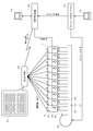
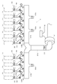
- FIG. 14 shows a configuration example of the exhaust device 6 connected to each exhaust port 38 of the plurality of parison molding mechanisms 10.
- the exhaust device 6 includes a blower 61, an exhaust pipe 67A having bifurcated branch pipes 67B and 67C, and a plurality of communication pipes 67D communicating with one of the branch pipes 67B and 67C.
- a suction force acts on the air lead-out paths Q of the plurality of parison molding mechanisms 10 via the exhaust pipes 67A, branch pipes 67B and 67C, and the respective communication pipes 67D. Is guided to the exhaust device 6.
- the rotational speed of the motor is controlled by an inverter 62.
- the exhaust pipe 67A is provided with an open / close valve 63 that is manually opened and closed.
- the suction force acting on the air lead-out path Q of each parison forming mechanism 10 can be adjusted by drive control of the blower 61 by the inverter 62 and opening degree control of the on-off valve 63.
- the magnitude of the suction force is set to an optimum value corresponding to the pressure of the exhaust air exhausted from the parison molding mechanism 10. If this suction force is set lower than the pressure of the exhaust air, foreign matter or the like existing in the vicinity of the outer peripheral portion of the plunger 1 cannot be exhausted together with the exhaust air. On the other hand, if the pressure is set higher than the pressure of the exhaust air, foreign matter floating outside the parison molding mechanism 10 is drawn.
- a butterfly valve 68 that is controlled to open and close by the valve drive mechanism 39 is interposed in each communication pipe 67D.
- Each valve drive mechanism 39 opens the butterfly valve 68 in accordance with the timing at which air is introduced into the plunger 1 of each parison molding mechanism 10, thereby opening the communication pipe 67 ⁇ / b> D and the suction force of the blower 61. Acts on the parison molding mechanism 10.
- Each natural exhaust port 66B closes the regulating valve 65 to check the pressure of exhaust air naturally exhausted from the parison molding mechanism 10, or exhausts the exhaust air naturally exhausted from the parison molding mechanism 10 from the communication pipe 67D. Open it when you want to let it go.
- the filter 69 is provided to remove foreign substances discharged from the parison molding mechanism 10 together with the exhaust air.
- a natural exhaust port 66A is also provided in the branch pipes 67B and 67C. These natural exhaust ports 66A are opened when exhaust air naturally exhausted from each parison forming mechanism 10 is exhausted from the branch pipes 67B and 67C when the blower 61 is stopped and parison molding is performed.
- FIG. 15 shows the relationship between the raising / lowering operation position of the plunger 1, the timing of supplying and stopping the cooling air, and the timing of applying a suction force to the parison molding mechanism 10.
- the raising / lowering operation position of the plunger 1 is determined by the reciprocating operation of the cylinder 11.
- the timing of supplying and stopping the cooling air is determined by the opening / closing operation of the operation valve 52 of the cooling device 5.
- the timing at which the suction force is applied to the parison molding mechanism 10 is determined by the opening / closing operation of the butterfly valve 68 of the exhaust device 6.
- the blower 61 of the exhaust device 6 is operated continuously.
- the butterfly valve 68 is opened at the time T1, and the suction force by the exhaust device 6 acts on the parison molding mechanism 10.
- the cooling device 5 starts supplying cooling air after a predetermined time ⁇ 1 has elapsed from the opening operation of the butterfly valve 68.
- the plunger 1 starts to rise after the gob is charged and before the cooling air is supplied.
- the reason why the suction force is applied prior to the supply of the cooling air and the raising operation of the plunger 1 is to remove foreign matters remaining in the parison molding mechanism 10 to the air outlet path Q.
- the cooling air is continuously supplied and the suction force is continuously applied to the parison molding mechanism 10 for a time period TA from immediately before the plunger 1 reaches the upper limit position to immediately after the descent start.
- the supply of the cooling air is stopped immediately after the plunger 1 starts to descend.
- the butterfly valve 68 is closed and the action of the suction force on the parison molding mechanism 10 is stopped.
- the suction force is applied even after the cooling air supply is stopped and when the plunger 1 is lowered, because the foreign matter remaining in the parison molding mechanism 10 is negatively generated by the lowering of the plunger 1. This is to prevent the pressure from entering the parison g.
- the plunger 1 When the plunger 1 is lowered to the lower limit position, the rough mold 40 of the mold 4 is opened, and the parison g held by the mouth mold 41 is transferred together with the mouth mold 41 to the finishing mold. After the parison g is delivered to the finishing mold, when the mouth mold 41 is returned to the rough mold 40, the plunger 1 is raised to the gob loading position, the gob is loaded, and the parison molding is restarted.
- the lower end surface 1c of the base end 1b of the plunger 1 and the upper end surface 101a of the adapter 101 are in contact with each other.
- the plunger 1 and the adapter 101 are kept connected only by a tensile force along the direction of the axis X by the connecting ring 102. For this reason, the holding state of the plunger 1 is not stable, and wear proceeds on the contact surface between the lower end surface 1c of the base end portion 1b of the plunger 1 and the upper end surface 101a of the adapter 101 during long-term use.
- the connection state with respect to the adapter 101 becomes unstable.
- the molten glass is not blended in the entire parison g in a balanced manner when the tip of the plunger 1 is tilted in the radial direction.
- the wall thickness of the parison g varies, and the strength of the portion having a particularly thin wall thickness is significantly reduced. Due to the significant decrease in strength, the glass bottles may be damaged due to the contact between the glass bottles in the manufacturing process or distribution process of the glass bottles.
- the lower end surface 1c of the base end portion 1b of the plunger 1 and the upper end surface 101a of the adapter 101 are in contact with each other, but if there is rattling or radial deflection of the plunger 1, the contact surface A gap is generated in the air, and cooling air and exhaust air leak from the gap, resulting in a decrease in cooling efficiency and exhaust efficiency.
- the foreign matter generated in the parison molding mechanism 10 is not sufficiently removed and adheres to the inner surface of the parison g, causing the strength of the parison g to decrease.
- the present invention has been made paying attention to the above problems, and by adopting a structure in which the base end portion of the plunger is held by the cylindrical portion of the adapter, the rattling of the plunger and the deflection in the radial direction are suppressed.
- a parison molding device that improves the sealing of the connecting part between the base end of the plunger and the adapter, and prevents the strength of the parison from deteriorating due to variations in wall thickness and adhesion of extraneous materials, especially for ultralight bottles. The purpose is to do.
- a parison molding apparatus includes a molding die into which a gob is introduced, a plunger that enters the molding die and molds the parison from the gob, and reciprocates the plunger with respect to the molding die.
- a cylinder and a cooling device for cooling the plunger by introducing air for cooling into the inside of the plunger are provided.
- the base end of the plunger is connected and held to the tip of the piston rod of the cylinder by a plunger holding mechanism.
- the plunger holding mechanism includes an adapter connected to a distal end portion of a piston rod, and the adapter integrally includes a cylindrical portion having a fitting hole that fits a cylindrical outer shape of a proximal end portion of the plunger. .
- the base end portion of the plunger is held in a fitted state in the fitting hole of the cylindrical portion, and a connecting ring for connecting the adapter and the base end portion of the plunger is fitted on the cylindrical portion of the adapter.
- the inside of the plunger communicates with an air lead-out path via an exhaust passage provided in the adapter, and the air lead-out path applies the suction force to the air lead-out path so that the cooled air is sent to the air lead-out path. It communicates with an exhaust device that guides and discharges to the outside.
- the base end portion of the plunger is securely held in the fitting hole of the cylindrical portion of the adapter in a fitted state. In the state where the plunger is tilted, it does not enter the molten glass.
- the distal end of the plunger is pulled out from the mold, excessive stress is not concentrated on the mouth of the parison, and the occurrence of chatter and chipping is prevented, and there is no possibility of hindering the plunger pulling operation.
- the molten glass is distributed in a balanced manner throughout the parison, the thickness distribution of the parison is good. In particular, for an ultralight bottle having a thin wall thickness over the entire glass bottle, a particularly thin portion of the wall thickness does not occur and the strength does not decrease.
- the base end of the plunger is fitted in the fitting hole of the cylindrical part of the adapter, and the sealing performance of the connecting portion between the base end of the plunger and the adapter is improved, so cooling due to leakage of cooling air or exhaust air There is no reduction in efficiency and exhaust efficiency.
- foreign matters generated in the parison molding mechanism are sufficiently removed, and there is no possibility that the strength of the parison is reduced due to adhesion of foreign matters to the inner surface of the parison.
- the exhaust device causes a suction force to constantly act on the air outlet passage.
- the suction force can be applied sufficiently long before the cooling air is supplied and the plunger is lifted, the foreign matter remaining in the parison molding mechanism is completely removed to the air lead-out path. be able to. Also, since the suction force is applied for a sufficiently long time when the cooling air supply and the plunger descend, the foreign matter remaining in the parison molding mechanism is moved into the parison by the negative pressure generated by the plunger descending. It is possible to completely prevent entry.
- the parison molding apparatus further includes a cooling mechanism that controls the temperature of the molding die by applying cooling air to the molding die.
- the cooling mechanism includes a temperature sensor that detects the temperature of the mold, a valve mechanism that opens and closes a passage that guides cooling air to the mold, and an operation amount of the valve mechanism based on a temperature detected by the mold by the temperature sensor. And a control device that controls the air volume of the cooling air determined by PID control.
- the operation amount of the valve mechanism is determined by PID control based on the temperature detected by the mold by the temperature sensor, and the air volume of the cooling air is controlled. Only by performing feedback control, the temperature of the mold can be controlled with high accuracy with a simple configuration. In particular, an ultra-light bottle having a thin wall thickness over the entire glass bottle is difficult to perform delicate temperature control, and it is possible to suppress molding defects such as bills and wrinkles.
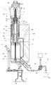
- FIG. 1 shows the overall configuration of a parison molding apparatus according to an embodiment of the present invention.
- the parison molding apparatus according to this embodiment is for molding a glass bottle with a thin wall thickness, and in particular, an ultralight bottle having a lightness index of less than 0.7 and called a “gas”.
- a parison is formed for forming a glass bottle containing the above.
- the “lightness index” (referred to as “L value”; see the Japan Glass Bottle Association website) is the lightness obtained by calculating the relationship between bottle capacity and bottle mass (glass consumption) as a function. Is an index indicating.
- the L value is obtained by dividing the bottle mass (g) by the 0.77th power of the bottle full capacity (ml) and multiplying it by a coefficient of 0.44.
- Bottles with an L value of 1.4 or more are “level 1”
- bottles of 1.0 or more and less than 1.4 are “level 2”
- bottles of 0.7 or more and less than 1.0 are “level 3”
- a bottle of less than 0.7 is read as “Level 4 (Ultralight Bottle)”.
- the parison molding apparatus in the illustrated example has a parison molding mechanism 10 for molding the parison g by allowing the plunger 1 to enter the molding die 4 into which the gob is introduced, and cools the plunger 1 by introducing cooling air into the plunger 1.
- the cooling device 5 is provided.
- the inside of the plunger 1 communicates with an air introduction path P for introducing cooling air and an air outlet path Q for leading air (exhaust air) after cooling the plunger 1 to the outside.
- the air lead-out path Q communicates with an exhaust device 6 that exhausts exhaust air by applying a suction force to the air lead-out path Q.
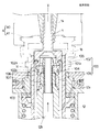
- the plunger 1 is connected to the tip of a hollow piston rod 12 by a plunger holding mechanism 2.
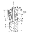
- the plunger holding mechanism 2 includes a cylindrical adapter 21 and a donut-shaped connection ring 22.
- a side shake prevention mechanism 31 that prevents the distal end portion of the plunger 1 from shaking in the radial direction is configured.
- a threaded portion 23 is formed on the inner peripheral surface of the lower portion of the adapter 21.
- An annular groove 24 is formed on the outer peripheral surface of the center portion of the adapter 21.
- the adapter 21 is fixed to the tip portion 12 a of the piston rod 12 by screwing the screw portion 23 of the adapter 21 into the screw portion 25 formed on the outer peripheral surface of the tip portion 12 a of the piston rod 12 of the cylinder 11.
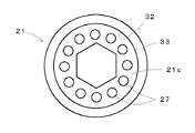
- the adapter 21 is integrally provided with a cylindrical tubular portion 33. As shown in FIGS. 2 and 3, the cylindrical portion 33 is provided with a fitting hole 32 having a circular planar shape that matches the cylindrical outer shape of the base end portion 1 b of the plunger 1. A lateral shake prevention mechanism that prevents the shaft center X of the plunger 1 from swinging in the radial direction by tightly fitting and holding the base end 1b of the plunger 1 in the fitting hole 32 of the cylindrical portion 33. 31 is configured.
- the adapter 21 is provided with a plurality of exhaust passages 27 for discharging exhaust air at equiangular positions. The outlet of each exhaust passage 27 opens below the lower end 22 b of the connection ring 22.
- the connecting ring 22 has a structure that can be divided into two in the radial direction, and is fitted on the cylindrical portion 33 of the adapter 21.
- the upper end portion 22 a of the connecting ring 22 is engaged with an annular step portion 29 formed on the base end portion 1 b of the plunger 1, and the lower end portion 22 b of the connecting ring 22 is an annular groove formed on the outer peripheral surface of the center portion of the adapter 21. 24 is engaged.
- the base end 1b of the plunger 1 is held in a state of being closely fitted in the fitting hole 32 of the cylindrical portion 33 of the adapter 21, so that the base of the plunger 1
- the end portion 1b does not slightly move in the radial direction and is stably held, and the base end portion 1b of the plunger 1 is covered with the cylindrical portion 33 of the adapter 21 in a state in which the outer peripheral surface is in close contact with each other so that the sealing performance is improved. Because it is raised, there is no leakage of cooling air or exhaust air.
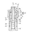
- FIG. 5 shows another embodiment of the plunger holding mechanism 2.
- the axial length L of the cylindrical portion 33 of the adapter 21 is set to a longer dimension than the embodiment of FIGS. 1 and 2, and the fitting surface of the fitting hole 32 is increased in the direction of the axis X. Is.
- the base end portion 1b of the plunger 1 is held more stably, and the above-described hermeticity is further enhanced.
- FIG. 6 shows still another embodiment of the plunger holding mechanism 2.
- the base end portion 1b of the plunger 1 is formed in a tapered shape, and the fitting hole 32 is formed so that the cylindrical portion 33 of the adapter 21 has an upwardly expanding taper that matches the outer shape of the base end portion 1b of the plunger 1.
- the contact area between the base end 1b of the plunger 1 and the cylindrical portion 33 of the adapter 21 is increased.
- the base end portion 1b of the plunger 1 is held more stably, and the above-described hermeticity is further enhanced.
- the inclination angle ⁇ of the fitting hole 32 with respect to the axis X is preferably 45 degrees or less, and particularly preferably 20 degrees or less, in order to prevent the lateral movement of the plunger 1.
- the air introduction path P and the air lead-out path Q and the configurations of the cooling device 5 and the exhaust device 6 are the same as those of the conventional example shown in FIGS.
- the detailed description is abbreviate
- the relationship between the raising / lowering operation position of the plunger 1 and the timing of supplying and stopping the cooling air is the same as that of the conventional example shown in FIG.
- the exhaust device 6 always applies the suction force to the air lead-out path Q without limiting the period as in the conventional example shown in FIG.
- the butterfly valve 68 shown in FIG. 14 becomes unnecessary, and the configuration can be simplified.
- the suction force is applied for a sufficiently long time before the cooling air is supplied and the plunger 1 is raised, the foreign matters remaining in the parison molding mechanism 10 can be completely removed to the air lead-out path Q.
- the suction force is applied for a sufficiently long time even when the supply of the cooling air and the lowering of the plunger 1 are finished, the foreign matter remaining in the parison molding mechanism 10 is generated in the parison g by the negative pressure generated by the lowering of the plunger 1. It can be completely prevented from entering.
- Subtle temperature control is difficult for ultra-light bottles, which is a factor that causes molding defects such as billiards and wrinkles.
- the occurrence of such molding defects is suppressed. Therefore, the temperature of the mold 4 is detected by a temperature sensor, and the amount of cooling air to be applied to the mold 4 is controlled based on the detected temperature.
- the temperature of the mold 4 can be controlled with high accuracy with a simple configuration that only detects the temperature of the mold 4 and performs feedback control.
- FIG. 7 shows a schematic configuration of the temperature control system of the mold 4 introduced in this embodiment.
- reference numeral 7 denotes a machine body of the bottle making machine.
- glass bottles are manufactured one after another and sent out to a bottle conveyance path (not shown).
- the molded glass bottle is conveyed to the slow cooling device through this bottle conveyance path.
- the glass bottle cooled by the slow cooling device is sent to the inspection process.
- the inspected bottle is transported to the packaging process.
- Each section S1 to S10 is provided with a rough mold 40 for forming a parison and a finishing mold (not shown) for finishing the parison transferred from the rough mold 40 into a final glass bottle.
- the rough mold 40 constitutes the mold 4 together with the mouth mold and the baffle.
- gobs are sequentially supplied at an appropriate timing by a gob supply mechanism (not shown).
- the bottles finished with the finishing molds of the sections S1 to S10 are sent out onto the conveyor constituting the bottle conveyance path.
- the operations of the sections S1 to S10 are controlled individually and in series by the timing setting system 70.
- the timing setting system 70 is a distributed processing system using a large number of microcomputers (hereinafter referred to as “MPUs”), so that various mechanisms included in the sections S1 to S10 operate in a predetermined order.
- a control signal (hereinafter collectively referred to as “timing signal”) for instructing the timing of starting and stopping the operation of each mechanism is generated and output.
- the rough mold 40 and the finishing mold are provided with a temperature sensor 8 for detecting the temperature of each mold embedded in the mold.
- Each temperature sensor 8 outputs an analog amount of temperature detection signal (for example, current value) having a magnitude proportional to the mold temperature.
- the temperature detection signal of the temperature sensor 3 provided in the rough mold 40 is input to the temperature display panel 80.
- the temperature detection signal of the temperature sensor 8 provided in the finishing mold is input to another temperature display panel (not shown).
- the temperature control of the rough mold 40 will be described, but the same applies to the temperature control of the finishing mold, and the description thereof is omitted here.
- the temperature display panel 80 has an A / D converter and ten temperature indicators 81.
- the A / D converter receives the temperature detection signal from the temperature sensor 3 of each rough mold 40 and converts it into a digital signal (hereinafter referred to as “current temperature data”).
- Each temperature indicator 81 digitally displays the temperature of the rough mold 40 of each section S1 to S10 according to the current temperature data.
- the current temperature data for each rough mold 40 is taken into the temperature control device 82 at regular intervals.
- the temperature control device 82 controls the opening / closing operation of a valve mechanism 90 described later based on the fetched current temperature data, and controls the amount of cooling air for cooling the rough mold 40.
- the timing at which the temperature control device 82 controls the amount of cooling air is controlled by a timing signal from the timing setting system 70.
- Each cooling mold 40 is provided with a cooling mechanism 9 for each mold.
- Each cooling mechanism 9 controls the temperature of each rough mold 40 by causing cooling air to act on each rough mold 40.
- the cooling mechanism 9 of this embodiment blows cooling air to the outer surface of the rough mold 40 to cool the rough mold 40 from the outside.
- the cooling mechanism 9 introduces cooling air into the cooling passage that penetrates the rough mold 40 to rough the rough mold 40.
- the mold 40 may be cooled from the inside.
- Each cooling mechanism 9 includes a cooling air passage 91 that guides the cooling air to the rough mold 40 and a valve mechanism 90 that opens and closes a branch passage 93 branched from the main passage 92 of the cooling air passage 91.
- the main passage 92 guides the cooling air generated by the blower 94 to ten branch passages 93.
- Each branch passage 93 guides the cooling air to an outlet (not shown) arranged around each rough mold 40.
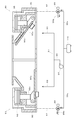
- FIG. 8 shows a specific example of the valve mechanism 90.
- 93 and 93 are two branch passages leading to separate rough molds 40, and the valves 90 a of the valve mechanisms 90 and 90 are arranged in the respective branch passages 93 so as to be capable of opening and closing.
- Each valve mechanism 90 includes an air cylinder 95 as an actuator. When air is supplied to the air cylinder 95 from the air passage 96, the piston rod 95a of the air cylinder 95 protrudes and the valve 90a is closed. When the supply of air to the air cylinder 95 is stopped, the valve 90a is pushed open under the wind pressure of the cooling air.
- the air passage 96 is connected with an air lead-in / out pipe 97.
- An air supply pipe 99 a and an exhaust pipe 99 b are connected to the air lead-in / out pipe 97 through an electromagnetic switching valve 98.
- the air supply pipe 99a communicates with the compressor 110, and the exhaust pipe 99b is open to the atmosphere.
- the electromagnetic switching valve 98 is switched to one side, air is supplied from the compressor 110 to the air cylinder 95 through the air supply pipe 99a, the air lead-in / out pipe 97, and the air passage 96.
- the electromagnetic switching valve 98 is switched to the other side, the air supplied to the air cylinder 95 passes outside through the air passage 96, the air lead-in / out pipe 97, and the exhaust pipe 99b.
- FIG. 9 shows a method for controlling the opening / closing operation of the valve mechanism 90.
- S is the length of time during which the valve is open, that is, the cooling time, and corresponds to the operation amount of the valve mechanism 90.
- the valve opens at time t1 and closes at time t2.
- a switching signal is given to the electromagnetic switching valve 98 at each time timing t1, t2.
- the valve opening amount can be used instead of the valve opening time S as the operation amount of the valve mechanism 90.
- the opening / closing operation of the valve mechanism 90 is controlled based on the temperature detected by the rough mold 40 by the temperature sensor 8, thereby controlling the amount of cooling air.
- the valve opening time S is determined by executing a calculation by PID control.
- the time timing t2 for closing the valve is fixed, and the time timing t1 for opening the valve is changed according to the calculation result, as indicated by an arrow in the figure.
- the target temperature of the rough mold 40 is T si and the current temperature of the rough mold 40 (corresponding to the “current temperature data” described above) is T pi
- the difference between the current temperature T pi and the target temperature T si is referred to as “temperature deviation.”
- ⁇ T i T pi ⁇ T si
- the current temperature data is taken into the temperature control device 82 at regular intervals and sequentially stored in a memory 84 to be described later.
- i is an argument for individually specifying the accumulated current temperature data.
- the argument i corresponding to the oldest stored data is ⁇ .
- the PID control is a combination of proportional control, integral control, and differential control.
- the arithmetic expression by the PID control includes a proportional term given by the product of the proportional coefficient A and the temperature deviation ⁇ T i, and an accumulation of the integral coefficient B and the temperature deviation ⁇ T i .
- the integral term given by the product of the value and the differential term given by the product of the differential coefficient C and the difference between the previous temperature deviation and the current temperature deviation ( ⁇ T 0 ⁇ T ⁇ 1 ) are included.
- the integration range is set from zero to negative infinity, as shown in the following equation (1), and from zero to negative infinity: for each temperature deviation [Delta] T i up, 2 i, i.e., 2 0, 2 -1, 2 -2, 2 -3, performs weighting of ....
- an arithmetic expression based on PID control is given by Expression (2).
- the integral term needs to be provided with an integration interval, but according to this embodiment, since the weighting is performed, the integration interval may not be provided.
- calculation by PID control is executed based on the above principle to obtain the operation amount of the valve mechanism 90 (opening time S of the valve 90a), and the operation of the valve 90a is calculated based on the calculation result.
- the operation result of the PID control exceeds a predetermined upper limit value in order to prevent the operating amount of the valve mechanism 90 from being determined to an extreme value and the temperature of the rough mold 40 from changing rapidly.
- the calculation result is corrected to the upper limit value when it falls, and to the lower limit value when it falls below the predetermined lower limit value.
- the current calculation result is set so that the difference from the previous calculation result becomes the threshold value. It shall be corrected.
- the valve 90 a is opened and closed by switching the electromagnetic switching valve 98, and a switching signal for the electromagnetic switching valve 98 is given by the temperature control device 82.
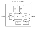
- FIG. 10 shows a detailed configuration of the temperature control device 82.
- This temperature control device 82 controls and operates the MPU 83, and includes a memory 84 for storing programs and data and a timer 85 for measuring the passage of time.
- the MPU 83 is connected to the operator terminal 73 and the temperature display panel 80 via communication interfaces 86 and 87. Further, the MPU 83 inputs a timing signal from the timing setting system 70 through the input interface 88 and outputs a switching signal to the electromagnetic switching valves 98 in the sections S1 to S10 through the output interface 89.
- the timing setting system 70 sets the operation timing of each part of the entire bottle making machine, and outputs a timing signal for instructing the temperature control device 82 to cool the rough mold 40 for each of the sections S1 to S10.
- the MPU 83 of the temperature control device 82 determines that it is time to cool the rough mold 40 of a predetermined section, determines the cooling time S, and the cooling At a timing based on the time S, a switching signal is sent to the electromagnetic switching valve 98 of the corresponding section.
- one operator terminal 72 is for inputting and setting the target temperature, coefficients A, B, and C for the PID control to the temperature control device 82.
- the other operator terminal 73 is for inputting and setting various data related to the operation of the bottle making machine to the timing setting system 70.
- FIG. 11 shows the flow of control when the MPU 83 of the temperature control device 82 determines the cooling time and executes cooling for each of the rough molds 40.
- ST is an abbreviation for “STEP” (step), and indicates each procedure in the flow of control.
- ST1 of the figure it is determined whether or not it is time to cool the rough mold 40 to be controlled.
- the timing signal from the timing setting system 70 is input, the determination in ST1 is “YES”, and it is then determined whether or not to perform an operation for calculating the cooling time (ST2). If the determination of ST2 is “YES”, the process proceeds to ST3. However, if the calculation is not executed every time, and if the determination of ST2 is “NO”, the process proceeds to ST13, and a preset cooling time is set. decide.
- the MPU 83 inquires the temperature display panel 80 about the temperature of the corresponding rough mold 40 (ST3). In response to this inquiry, when current temperature data is transmitted from the temperature display panel 80, the determination in ST4 is “YES”, and the current temperature data is stored in the memory 84 (ST5).
- the MPU 83 calculates the cooling time S by executing the calculation by the PID control described above (ST6). That is, the current temperature data corresponding to the value of i is read while changing the value of i in order from 0, and the temperature deviation is obtained from the current temperature data and the target temperature input from the operator terminal 72. Then, the cooling time S is calculated by applying the temperature deviation ⁇ T i obtained for each value of i to the equation (2). According to the equation (2), the calculation using all the current temperature data stored in the temperature control device 82 is executed. However, the present invention is not limited to this. Data may be read out and the calculation may be executed.
- the next ST7 it is determined whether or not the calculation result is within a predetermined range. If the calculation result is within the predetermined range, it is determined that the first criterion is satisfied, the determination in ST7 is “YES”, and the calculation result is not corrected. If the calculation result is not within the predetermined range, it is determined that the first reference is not satisfied, the determination of ST7 is “NO”, and the MPU 83 executes the first correction process (ST8).
- the first correction process is to correct the calculation result to an upper limit value when the calculation result exceeds a predetermined upper limit value, and to the lower limit value when the calculation result falls below a predetermined lower limit value.
- ST9 it is determined whether or not the difference between the current calculation result (corrected data if there is a first correction process) and the previous calculation result exceeds a predetermined threshold value. If the current calculation result does not exceed the threshold value, it is determined that the second criterion is satisfied, and the determination in ST9 is “YES”. If the calculation result exceeds the threshold value, it is determined that the second criterion is not satisfied, the determination in ST9 is “NO”, and the MPU 83 executes the second correction process (ST10).
- the second correction process is to correct the current calculation result so that the difference from the previous calculation result becomes the threshold value.
- the cooling time obtained through the above procedure is determined as the current cooling time for the corresponding rough mold 40 and stored in the memory 84 (ST11), and then, based on the determined cooling time, the valve mechanism 90 An opening / closing operation is performed to perform a cooling process (ST12). The same procedure is executed for the other rough molds 40 to determine the cooling time and execute the cooling.
- the base end portion of the plunger 1 is firmly held in the fitting hole 32 of the cylindrical portion 33 of the adapter 21 in the fitted state, and therefore the rattle of the base end portion 1b of the plunger 1 is At the same time, radial deflection of the tip of the plunger 1 is suppressed, and the plunger 1 does not enter the molten glass in a tilted state.
- the distal end portion of the plunger 1 is pulled out from the mold, excessive stress is not concentrated on the mouth portion of the parison g, the occurrence of chatter and chipping is prevented, and the pulling operation of the plunger 1 is not hindered.
- the wall thickness distribution of the parison g is improved.
- a portion having a particularly thin wall thickness does not occur and the strength does not decrease.
- the base end portion 1b of the plunger 1 is tightly fitted into the fitting hole 32 of the cylindrical portion 33 of the adapter 21, the sealing performance of the connecting portion between the base end portion 1b of the plunger 1 and the adapter 21 is improved. Therefore, the cooling efficiency and the exhaust efficiency are not lowered due to the leakage of the cooling air and the exhaust air.
- foreign matters generated in the parison molding mechanism 10 are sufficiently removed, and there is no possibility that the strength of the parison g is reduced due to adhesion of foreign matters to the inner surface of the parison g.
- the operation amount of the valve mechanism 90 is determined by PID control based on the temperature detected by the temperature sensor 8 by the rough mold 40, and the cooling air volume is controlled. Therefore, the temperature of the rough mold 40 is detected and feedback control is performed.
- the temperature of the rough mold 40 can be controlled with high accuracy with a simple configuration. In particular, an ultra-light bottle having a thin wall thickness over the entire glass bottle is difficult to perform delicate temperature control, and it is possible to suppress molding defects such as bills and wrinkles.
Landscapes
- Engineering & Computer Science (AREA)
- Chemical & Material Sciences (AREA)
- Manufacturing & Machinery (AREA)
- Materials Engineering (AREA)
- Organic Chemistry (AREA)
- Mechanical Engineering (AREA)
- Blow-Moulding Or Thermoforming Of Plastics Or The Like (AREA)
Abstract
Description
ここで、冷却エアの供給とプランジャ1の上昇動作とに先だって吸引力を作用させるのは、パリソン成形機構10に残存している異物などを空気導出路Qへ除去しておくためである。
ここで、冷却エアの供給停止後とプランジャ1が下降している時点においても吸引力を作用させているのは、パリソン成形機構10に残存している異物などを、プランジャ1の下降により生じる負圧によってパリソンg内へ入り込まないようにするためである。
この実施態様によると、冷却エアの供給とプランジャの上昇動作とに先だって十分に長く吸引力を作用させることができるので、パリソン成形機構に残存している異物などを空気導出路へ完全に除去することができる。また、冷却エアの供給とプランジャの下降が終了した時点においても十分に長く吸引力を作用させているので、パリソン成形機構に残存している異物などがプランジャの下降により生じる負圧によってパリソン内へ入り込むのを完全に防止できる。
この実施例のパリソン成形装置は、びん全体の肉厚が薄いガラスびんを成形するものであり、特に、軽量度指数が0.7未満の超軽量びんであって「ガス物」と呼ばれる炭酸飲料を内容物とするガラスびんを成形するためのパリソンを成形するものである。ここで、「軽量度指数」(「L値」と呼ばれる。日本ガラスびん協会のホームページ参照)とは、びんの容量とびんの質量(ガラス使用量)との関係を関数で求めた、軽量度を示す指数である。具体的にいえば、びんの質量(g)をびんの満量容量(ml)の0.77乗で割り、それに0.44という係数を掛けることでL値が求められる。このL値が1.4以上のびんを「レベル1」、1.0以上、1.4未満のびんを「レベル2」、0.7以上、1.0未満のびんを「レベル3」、0.7未満のびんを「レベル4(超軽量びん)」と読んでいる。
また、長期の使用によって、プランジャ1の基端部1bの下端面1cとアダプタ21の嵌合穴32内の上面21cとの当接面に磨耗が進行しても、プランジャ1の基端部1bはアダプタ21の筒状部33により外周面が密接した状態で保持されているので、プランジャ1の横振れが防止される。このため、成形後にプランジャ1の先端部を成形型4から引き抜く際に、パリソンMの口部などに対する応力の集中が回避され、成形品にビリが発生せず、プランジャ1の引抜動作が円滑に行われる。
この実施例は、アダプタ21の筒状部33の軸長Lを図1および図2の実施例より長い寸法に設定して、嵌合穴32の嵌合面を軸心Xの方向に大きくしたものである。この実施例によると、プランジャ1の基端部1bが一層安定して保持されるとともに、上記の密閉性が一層高められている。
この実施例は、プランジャ1の基端部1bを先細り形状に形成すると共に、アダプタ21の筒状部33にプランジャ1の基端部1bの外形に適合する上広がりのテーパをなす嵌合穴32を形成して、プランジャ1の基端部1bとアダプタ21の筒状部33との接触面積を大きくしたものである。この実施例によると、プランジャ1の基端部1bが一層安定して保持されるとともに、上記の密閉性が一層高められている。前記嵌合穴32の軸心Xに対する傾斜角度θは、プランジャ1の横振れを防止するうえで、45度以下、特に20度以下が望ましい。
各弁機構90は、アクチュエータとしてのエアーシリンダ95をそれぞれ含んでいる。そのエアーシリンダ95へ空気通路96から空気が供給されると、エアーシリンダ95のピストンロッド95aが突き出て、弁90aが閉動作する。エアーシリンダ95への空気の供給を停止すると、冷却風の風圧を受けて、弁90aが押し開かれる。
前記現在温度データは、一定時間毎に温度制御装置82に取り込まれ、後記するメモリ84に順次蓄積される。iは、蓄積された現在温度データを個別に特定するための引数であり、最新のデータにi=0を対応させ、過去に遡る方向に沿って、i=-1,-2,-3・・・とする。なお、以下では、蓄積されているデータの中の最も古いものに対応する引数iを-∞とする。
通常、PID制御では前記積分項は積分の区間を設ける必要があるが、この実施例によると、重み付けを行っているので積分区間を設けなくてもよい。

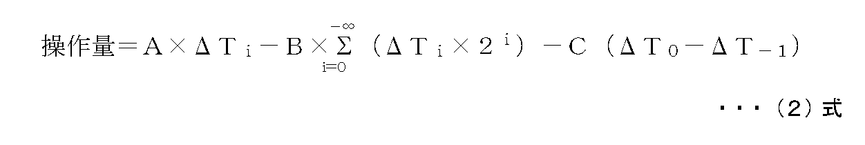
図10は、温度制御装置82の詳細な構成を示す。この温度制御装置82は、MPU83を制御、演算の主体とし、プログラムやデータを記憶するためのメモリ84や時間経過を計測するタイマ85を含んでいる。また、このMPU83は、通信インターフェイス86,87を介してオペレータ端末73や温度表示盤80に接続されている。さらに、MPU83は、入力インターフェイス88を介して前記タイミング設定システム70からのタイミング信号を入力するとともに、出力インターフェイス89を介して、各セクションS1~S10の前記電磁切替弁98に切替信号を出力する。
同図のST1では、制御対象の粗型40を冷却するタイミングになったかどうかを判定している。ここで、タイミング設定システム70からのタイミング信号を入力すると、ST1の判定が「YES」となり、つぎに冷却時間を算出する演算を実行するかどうかが判定される(ST2)。ST2の判定が「YES」であれば、ST3へ進むが、毎回演算を実行しない場合であって、ST2の判定が「NO」である場合はST13へ進み、あらかじめ設定された規定の冷却時間に決定する。
さらに、プランジャ1の基端部1bがアダプタ21の筒状部33の嵌合穴32に緊密に嵌合されるので、プランジャ1の基端部1bとアダプタ21との連結部分の密閉性が高められ、冷却エアや排気エアの漏れによる冷却効率や排気効率の低下を招くことがない。その結果、パリソン成形機構10内で発生する異物などが十分に除去され、異物等のパリソンgの内面への付着に起因するパリソンgの強度低下を招くおそれがない。
2 プランジャ保持機構
4 成形型
5 冷却装置
6 排気装置
11 シリンダ
12 ピストンロッド
21 アダプタ
22 連結リング
27 排気通路
32 嵌合穴
33 筒状部
40 粗型
82 温度制御装置
90 弁機構
P 空気導入路
Q 空気導出路
Claims (3)
- ゴブが導入される成形型と、成形型内へ進入して成形型との間で前記ゴブよりパリソンを成形するプランジャと、成形型に対してプランジャを往復動させるシリンダと、プランジャの内部へ冷却のための空気を導入してプランジャを冷却するための冷却装置とを備えるパリソン成形装置において、
前記プランジャは、その基端部が前記シリンダのピストンロッドの先端部にプランジャ保持機構により連結保持されており、前記プランジャ保持機構は、ピストンロッドの先端部に連結されるアダプタを有し、前記アダプタはプランジャの基端部の筒状の外形に適合する嵌合穴を有する筒状部を一体に備えており、前記筒状部の嵌合穴にプランジャの基端部が嵌合状態で保持されるとともに、前記アダプタの筒状部上にアダプタとプランジャの基端部とを連結する連結リングが嵌められており、前記プランジャの内部は、前記アダプタに設けられた排気通路を介して空気導出路と連通し、前記空気導出路は、空気導出路に吸引力を作用させることにより冷却後の空気を空気導出路へ導いて外部へ排出する排気装置に連通させて成るパリソン成形装置。 - 前記排気装置は、前記空気導出路に吸引力を常時作用させるものである請求項1に記載されたパリソン成形装置。
- 請求項1に記載されたパリソン成形装置であって、前記成形型に冷却風を作用させて成形型の温度を制御する冷却機構をさらに備えたものであり、前記冷却機構は、成形型の温度を検出する温度センサと、成形型へ冷却風を導く通路を開閉する弁機構と、前記温度センサによる成形型の検出温度に基づいて前記弁機構の操作量をPID制御により決定して冷却風の風量を制御する制御装置とを含んでいるパリソン成形装置。
Priority Applications (4)
| Application Number | Priority Date | Filing Date | Title |
|---|---|---|---|
| JP2015508405A JPWO2014156941A1 (ja) | 2013-03-26 | 2014-03-20 | パリソン成形装置 |
| EP14774251.4A EP2980032A4 (en) | 2013-03-26 | 2014-03-20 | PREFORM PRODUCTION DEVICE |
| CN201480017597.9A CN105228960A (zh) | 2013-03-26 | 2014-03-20 | 型坯成形装置 |
| US14/780,524 US20160052817A1 (en) | 2013-03-26 | 2014-03-20 | Parison forming apparatus |
Applications Claiming Priority (2)
| Application Number | Priority Date | Filing Date | Title |
|---|---|---|---|
| JP2013-064689 | 2013-03-26 | ||
| JP2013064689 | 2013-03-26 |
Publications (1)
| Publication Number | Publication Date |
|---|---|
| WO2014156941A1 true WO2014156941A1 (ja) | 2014-10-02 |
Family
ID=51623920
Family Applications (1)
| Application Number | Title | Priority Date | Filing Date |
|---|---|---|---|
| PCT/JP2014/057727 Ceased WO2014156941A1 (ja) | 2013-03-26 | 2014-03-20 | パリソン成形装置 |
Country Status (5)
| Country | Link |
|---|---|
| US (1) | US20160052817A1 (ja) |
| EP (1) | EP2980032A4 (ja) |
| JP (1) | JPWO2014156941A1 (ja) |
| CN (1) | CN105228960A (ja) |
| WO (1) | WO2014156941A1 (ja) |
Cited By (1)
| Publication number | Priority date | Publication date | Assignee | Title |
|---|---|---|---|---|
| JP2018538232A (ja) * | 2015-12-15 | 2018-12-27 | ビトロ、エセ.ア.ベ. デ セ.ウベ. | ガラス容器成形機用の金型冷却方法及びシステム |
Families Citing this family (3)
| Publication number | Priority date | Publication date | Assignee | Title |
|---|---|---|---|---|
| ES2706877T3 (es) * | 2014-11-13 | 2019-04-01 | Gerresheimer Glas Gmbh | Filtro de partículas de máquina para conformar vidrio, unidad de émbolo, cabeza de soplado, soporte de cabeza de soplado y máquina para conformar vidrio adaptada a dicho filtro o que lo comprende |
| IT201600126942A1 (it) * | 2016-12-15 | 2018-06-15 | Officina Stampi Sta Ve S R L Di Claudio E Marco Spinardi | Stelo raffreddatore nella produzione di contenitori in vetro. |
| US11795093B2 (en) * | 2018-03-29 | 2023-10-24 | Emhart Glass S.A. | Multivariable vertical glass distribution control using soft sensor and methods |
Citations (4)
| Publication number | Priority date | Publication date | Assignee | Title |
|---|---|---|---|---|
| JPH06219751A (ja) * | 1992-12-18 | 1994-08-09 | Emhart Glass Mach Investments Inc | ガラス容器成形機械 |
| JPH11209129A (ja) * | 1998-01-26 | 1999-08-03 | Nihon Yamamura Glass Co Ltd | 中空容器成形方法およびその装置 |
| JP2001294431A (ja) * | 2000-04-11 | 2001-10-23 | Nihon Yamamura Glass Co Ltd | パリソン成形方法およびパリソン成形装置 |
| JP2011136853A (ja) * | 2009-12-28 | 2011-07-14 | Nihon Yamamura Glass Co Ltd | ガラス製品成形装置、及び成形型の冷却方法 |
Family Cites Families (5)
| Publication number | Priority date | Publication date | Assignee | Title |
|---|---|---|---|---|
| US4033744A (en) * | 1975-09-18 | 1977-07-05 | Ball Corporation | Plunger assembly for a glass forming machine |
| US4708730A (en) * | 1984-04-16 | 1987-11-24 | Aga Ab | Apparatus for blow molding glass articles |
| US4659357A (en) * | 1985-09-23 | 1987-04-21 | Ball Corporation | Fan air cooling of neck ring and parison mold |
| US6286339B1 (en) * | 2000-01-28 | 2001-09-11 | Owens-Brockway Glass Container Inc. | Glass container forming machine plunger assembly |
| JP5328303B2 (ja) * | 2008-11-13 | 2013-10-30 | キヤノン株式会社 | 光学素子の製造装置及びその製造方法 |
-
2014
- 2014-03-20 US US14/780,524 patent/US20160052817A1/en not_active Abandoned
- 2014-03-20 CN CN201480017597.9A patent/CN105228960A/zh active Pending
- 2014-03-20 WO PCT/JP2014/057727 patent/WO2014156941A1/ja not_active Ceased
- 2014-03-20 JP JP2015508405A patent/JPWO2014156941A1/ja active Pending
- 2014-03-20 EP EP14774251.4A patent/EP2980032A4/en not_active Withdrawn
Patent Citations (5)
| Publication number | Priority date | Publication date | Assignee | Title |
|---|---|---|---|---|
| JPH06219751A (ja) * | 1992-12-18 | 1994-08-09 | Emhart Glass Mach Investments Inc | ガラス容器成形機械 |
| JPH11209129A (ja) * | 1998-01-26 | 1999-08-03 | Nihon Yamamura Glass Co Ltd | 中空容器成形方法およびその装置 |
| JP2001294431A (ja) * | 2000-04-11 | 2001-10-23 | Nihon Yamamura Glass Co Ltd | パリソン成形方法およびパリソン成形装置 |
| JP4392107B2 (ja) | 2000-04-11 | 2009-12-24 | 日本山村硝子株式会社 | パリソン成形方法およびパリソン成形装置 |
| JP2011136853A (ja) * | 2009-12-28 | 2011-07-14 | Nihon Yamamura Glass Co Ltd | ガラス製品成形装置、及び成形型の冷却方法 |
Non-Patent Citations (1)
| Title |
|---|
| See also references of EP2980032A4 |
Cited By (3)
| Publication number | Priority date | Publication date | Assignee | Title |
|---|---|---|---|---|
| JP2018538232A (ja) * | 2015-12-15 | 2018-12-27 | ビトロ、エセ.ア.ベ. デ セ.ウベ. | ガラス容器成形機用の金型冷却方法及びシステム |
| EP3392213A4 (en) * | 2015-12-15 | 2019-08-07 | Vitro, S.A.B. de C.V. | SYSTEM AND METHOD FOR COOLING SHAPES FOR A MACHINE FOR FORMING HOLLOWED GLASS OBJECTS |
| US10899649B2 (en) | 2015-12-15 | 2021-01-26 | Vitro, S.A.B. De C.V. | System and method for cooling moulds for a machine used to form hollow glass items |
Also Published As
| Publication number | Publication date |
|---|---|
| JPWO2014156941A1 (ja) | 2017-02-16 |
| US20160052817A1 (en) | 2016-02-25 |
| EP2980032A4 (en) | 2016-12-28 |
| EP2980032A1 (en) | 2016-02-03 |
| CN105228960A (zh) | 2016-01-06 |
Similar Documents
| Publication | Publication Date | Title |
|---|---|---|
| WO2014156941A1 (ja) | パリソン成形装置 | |
| CN103547394B (zh) | 真空压铸机 | |
| CN100335207C (zh) | 模铸装置以及减压铸造方法 | |
| US8978421B2 (en) | Muffle tube inspection method and manufacturing method of silica glass-based optical fiber preform | |
| WO2016103369A1 (ja) | 低圧鋳造装置及び低圧鋳造方法 | |
| CN105073662A (zh) | 用于制造光纤预制体和光纤的方法 | |
| JP4355316B2 (ja) | ガラス成形機 | |
| HK1212652A1 (zh) | 加压铸造方法及其装置 | |
| CN105067399A (zh) | 一种内控标准样品的制作方法 | |
| CN116493195B (zh) | 一种在线式真空灌胶机及其控制方法 | |
| US20070051135A1 (en) | Method for manufacturing porous-glass material for optical fiber, and glass base material | |
| EP1820585B1 (en) | Holding furnace for supplying fixed amount of molten metal | |
| JP4392107B2 (ja) | パリソン成形方法およびパリソン成形装置 | |
| JPH11285813A (ja) | 給湯用ラドルの給湯量設定方法および装置 | |
| US20080110206A1 (en) | Optical element molding method and apparatus | |
| JP6292835B2 (ja) | 光学素子製造装置および光学素子製造方法 | |
| JP2003145261A (ja) | ダイカストマシンの吸引給湯方法及び同方法を用いた吸引給湯装置 | |
| JP2001205425A (ja) | 自動給湯装置 | |
| JPH06304738A (ja) | 差圧鋳造における炉内加圧制御方法 | |
| JP4566673B2 (ja) | 光学素子の成形方法及び装置 | |
| CN213179364U (zh) | 一种烧结炉排气箱 | |
| JPS59215265A (ja) | 溶湯定量汲出し装置 | |
| JPS59215264A (ja) | 溶湯定量汲出し装置 | |
| CN105057633B (zh) | 一种定量金属液真空汲取装置 | |
| KR20140098376A (ko) | 인고트 제조 설비 |
Legal Events
| Date | Code | Title | Description |
|---|---|---|---|
| WWE | Wipo information: entry into national phase |
Ref document number: 201480017597.9 Country of ref document: CN |
|
| 121 | Ep: the epo has been informed by wipo that ep was designated in this application |
Ref document number: 14774251 Country of ref document: EP Kind code of ref document: A1 |
|
| ENP | Entry into the national phase |
Ref document number: 2015508405 Country of ref document: JP Kind code of ref document: A |
|
| WWE | Wipo information: entry into national phase |
Ref document number: 14780524 Country of ref document: US |
|
| NENP | Non-entry into the national phase |
Ref country code: DE |
|
| WWE | Wipo information: entry into national phase |
Ref document number: 2014774251 Country of ref document: EP |