WO2014157286A1 - エンジン装置 - Google Patents
エンジン装置 Download PDFInfo
- Publication number
- WO2014157286A1 WO2014157286A1 PCT/JP2014/058431 JP2014058431W WO2014157286A1 WO 2014157286 A1 WO2014157286 A1 WO 2014157286A1 JP 2014058431 W JP2014058431 W JP 2014058431W WO 2014157286 A1 WO2014157286 A1 WO 2014157286A1
- Authority
- WO
- WIPO (PCT)
- Prior art keywords
- pipe
- exhaust gas
- case
- urea mixing
- tube
- Prior art date
- Legal status (The legal status is an assumption and is not a legal conclusion. Google has not performed a legal analysis and makes no representation as to the accuracy of the status listed.)
- Ceased
Links
Images















Classifications
-
- F—MECHANICAL ENGINEERING; LIGHTING; HEATING; WEAPONS; BLASTING
- F01—MACHINES OR ENGINES IN GENERAL; ENGINE PLANTS IN GENERAL; STEAM ENGINES
- F01N—GAS-FLOW SILENCERS OR EXHAUST APPARATUS FOR MACHINES OR ENGINES IN GENERAL; GAS-FLOW SILENCERS OR EXHAUST APPARATUS FOR INTERNAL-COMBUSTION ENGINES
- F01N3/00—Exhaust or silencing apparatus having means for purifying, rendering innocuous, or otherwise treating exhaust
- F01N3/02—Exhaust or silencing apparatus having means for purifying, rendering innocuous, or otherwise treating exhaust for cooling, or for removing solid constituents of, exhaust
- F01N3/021—Exhaust or silencing apparatus having means for purifying, rendering innocuous, or otherwise treating exhaust for cooling, or for removing solid constituents of, exhaust by means of filters
- F01N3/033—Exhaust or silencing apparatus having means for purifying, rendering innocuous, or otherwise treating exhaust for cooling, or for removing solid constituents of, exhaust by means of filters in combination with other devices
- F01N3/035—Exhaust or silencing apparatus having means for purifying, rendering innocuous, or otherwise treating exhaust for cooling, or for removing solid constituents of, exhaust by means of filters in combination with other devices with catalytic reactors
-
- F—MECHANICAL ENGINEERING; LIGHTING; HEATING; WEAPONS; BLASTING
- F01—MACHINES OR ENGINES IN GENERAL; ENGINE PLANTS IN GENERAL; STEAM ENGINES
- F01N—GAS-FLOW SILENCERS OR EXHAUST APPARATUS FOR MACHINES OR ENGINES IN GENERAL; GAS-FLOW SILENCERS OR EXHAUST APPARATUS FOR INTERNAL-COMBUSTION ENGINES
- F01N13/00—Exhaust or silencing apparatus characterised by constructional features
- F01N13/009—Exhaust or silencing apparatus characterised by constructional features having two or more separate purifying devices arranged in series
-
- F—MECHANICAL ENGINEERING; LIGHTING; HEATING; WEAPONS; BLASTING
- F01—MACHINES OR ENGINES IN GENERAL; ENGINE PLANTS IN GENERAL; STEAM ENGINES
- F01N—GAS-FLOW SILENCERS OR EXHAUST APPARATUS FOR MACHINES OR ENGINES IN GENERAL; GAS-FLOW SILENCERS OR EXHAUST APPARATUS FOR INTERNAL-COMBUSTION ENGINES
- F01N13/00—Exhaust or silencing apparatus characterised by constructional features
- F01N13/009—Exhaust or silencing apparatus characterised by constructional features having two or more separate purifying devices arranged in series
- F01N13/0097—Exhaust or silencing apparatus characterised by constructional features having two or more separate purifying devices arranged in series the purifying devices are arranged in a single housing
-
- F—MECHANICAL ENGINEERING; LIGHTING; HEATING; WEAPONS; BLASTING
- F01—MACHINES OR ENGINES IN GENERAL; ENGINE PLANTS IN GENERAL; STEAM ENGINES
- F01N—GAS-FLOW SILENCERS OR EXHAUST APPARATUS FOR MACHINES OR ENGINES IN GENERAL; GAS-FLOW SILENCERS OR EXHAUST APPARATUS FOR INTERNAL-COMBUSTION ENGINES
- F01N13/00—Exhaust or silencing apparatus characterised by constructional features
- F01N13/14—Exhaust or silencing apparatus characterised by constructional features having thermal insulation
- F01N13/141—Double-walled exhaust pipes or housings
-
- F—MECHANICAL ENGINEERING; LIGHTING; HEATING; WEAPONS; BLASTING
- F01—MACHINES OR ENGINES IN GENERAL; ENGINE PLANTS IN GENERAL; STEAM ENGINES
- F01N—GAS-FLOW SILENCERS OR EXHAUST APPARATUS FOR MACHINES OR ENGINES IN GENERAL; GAS-FLOW SILENCERS OR EXHAUST APPARATUS FOR INTERNAL-COMBUSTION ENGINES
- F01N13/00—Exhaust or silencing apparatus characterised by constructional features
- F01N13/18—Construction facilitating manufacture, assembly, or disassembly
- F01N13/1838—Construction facilitating manufacture, assembly, or disassembly characterised by the type of connection between parts of exhaust or silencing apparatus, e.g. between housing and tubes, between tubes and baffles
-
- F—MECHANICAL ENGINEERING; LIGHTING; HEATING; WEAPONS; BLASTING
- F01—MACHINES OR ENGINES IN GENERAL; ENGINE PLANTS IN GENERAL; STEAM ENGINES
- F01N—GAS-FLOW SILENCERS OR EXHAUST APPARATUS FOR MACHINES OR ENGINES IN GENERAL; GAS-FLOW SILENCERS OR EXHAUST APPARATUS FOR INTERNAL-COMBUSTION ENGINES
- F01N3/00—Exhaust or silencing apparatus having means for purifying, rendering innocuous, or otherwise treating exhaust
- F01N3/08—Exhaust or silencing apparatus having means for purifying, rendering innocuous, or otherwise treating exhaust for rendering innocuous
- F01N3/10—Exhaust or silencing apparatus having means for purifying, rendering innocuous, or otherwise treating exhaust for rendering innocuous by thermal or catalytic conversion of noxious components of exhaust
- F01N3/18—Exhaust or silencing apparatus having means for purifying, rendering innocuous, or otherwise treating exhaust for rendering innocuous by thermal or catalytic conversion of noxious components of exhaust characterised by methods of operation; Control
- F01N3/20—Exhaust or silencing apparatus having means for purifying, rendering innocuous, or otherwise treating exhaust for rendering innocuous by thermal or catalytic conversion of noxious components of exhaust characterised by methods of operation; Control specially adapted for catalytic conversion
- F01N3/206—Adding periodically or continuously substances to exhaust gases for promoting purification, e.g. catalytic material in liquid form, NOx reducing agents
- F01N3/2066—Selective catalytic reduction [SCR]
-
- F—MECHANICAL ENGINEERING; LIGHTING; HEATING; WEAPONS; BLASTING
- F01—MACHINES OR ENGINES IN GENERAL; ENGINE PLANTS IN GENERAL; STEAM ENGINES
- F01N—GAS-FLOW SILENCERS OR EXHAUST APPARATUS FOR MACHINES OR ENGINES IN GENERAL; GAS-FLOW SILENCERS OR EXHAUST APPARATUS FOR INTERNAL-COMBUSTION ENGINES
- F01N2340/00—Dimensional characteristics of the exhaust system, e.g. length, diameter or volume of the exhaust apparatus; Spatial arrangements of exhaust apparatuses
- F01N2340/04—Arrangement of the exhaust system relative to a vehicle or parts thereof
-
- F—MECHANICAL ENGINEERING; LIGHTING; HEATING; WEAPONS; BLASTING
- F01—MACHINES OR ENGINES IN GENERAL; ENGINE PLANTS IN GENERAL; STEAM ENGINES
- F01N—GAS-FLOW SILENCERS OR EXHAUST APPARATUS FOR MACHINES OR ENGINES IN GENERAL; GAS-FLOW SILENCERS OR EXHAUST APPARATUS FOR INTERNAL-COMBUSTION ENGINES
- F01N2590/00—Exhaust or silencing apparatus adapted to particular use, e.g. for military applications, airplanes, submarines
- F01N2590/08—Exhaust or silencing apparatus adapted to particular use, e.g. for military applications, airplanes, submarines for heavy duty applications, e.g. trucks, buses, tractors, locomotives
-
- F—MECHANICAL ENGINEERING; LIGHTING; HEATING; WEAPONS; BLASTING
- F01—MACHINES OR ENGINES IN GENERAL; ENGINE PLANTS IN GENERAL; STEAM ENGINES
- F01N—GAS-FLOW SILENCERS OR EXHAUST APPARATUS FOR MACHINES OR ENGINES IN GENERAL; GAS-FLOW SILENCERS OR EXHAUST APPARATUS FOR INTERNAL-COMBUSTION ENGINES
- F01N2610/00—Adding substances to exhaust gases
- F01N2610/02—Adding substances to exhaust gases the substance being ammonia or urea
-
- F—MECHANICAL ENGINEERING; LIGHTING; HEATING; WEAPONS; BLASTING
- F01—MACHINES OR ENGINES IN GENERAL; ENGINE PLANTS IN GENERAL; STEAM ENGINES
- F01N—GAS-FLOW SILENCERS OR EXHAUST APPARATUS FOR MACHINES OR ENGINES IN GENERAL; GAS-FLOW SILENCERS OR EXHAUST APPARATUS FOR INTERNAL-COMBUSTION ENGINES
- F01N2610/00—Adding substances to exhaust gases
- F01N2610/14—Arrangements for the supply of substances, e.g. conduits
- F01N2610/1453—Sprayers or atomisers; Arrangement thereof in the exhaust apparatus
-
- F—MECHANICAL ENGINEERING; LIGHTING; HEATING; WEAPONS; BLASTING
- F16—ENGINEERING ELEMENTS AND UNITS; GENERAL MEASURES FOR PRODUCING AND MAINTAINING EFFECTIVE FUNCTIONING OF MACHINES OR INSTALLATIONS; THERMAL INSULATION IN GENERAL
- F16L—PIPES; JOINTS OR FITTINGS FOR PIPES; SUPPORTS FOR PIPES, CABLES OR PROTECTIVE TUBING; MEANS FOR THERMAL INSULATION IN GENERAL
- F16L39/00—Joints or fittings for double-walled or multi-channel pipes or pipe assemblies
- F16L39/005—Joints or fittings for double-walled or multi-channel pipes or pipe assemblies for concentric pipes
-
- Y—GENERAL TAGGING OF NEW TECHNOLOGICAL DEVELOPMENTS; GENERAL TAGGING OF CROSS-SECTIONAL TECHNOLOGIES SPANNING OVER SEVERAL SECTIONS OF THE IPC; TECHNICAL SUBJECTS COVERED BY FORMER USPC CROSS-REFERENCE ART COLLECTIONS [XRACs] AND DIGESTS
- Y02—TECHNOLOGIES OR APPLICATIONS FOR MITIGATION OR ADAPTATION AGAINST CLIMATE CHANGE
- Y02T—CLIMATE CHANGE MITIGATION TECHNOLOGIES RELATED TO TRANSPORTATION
- Y02T10/00—Road transport of goods or passengers
- Y02T10/10—Internal combustion engine [ICE] based vehicles
- Y02T10/12—Improving ICE efficiencies
Definitions
- the present invention relates to an engine device such as a diesel engine mounted on an agricultural machine (tractor, combine) or construction machine (bulldozer, hydraulic excavator, loader), and more specifically, particulate matter contained in exhaust gas (
- the present invention relates to an engine device equipped with an exhaust gas purification device that removes soot, particulates, or nitrogen oxides (NOx) contained in exhaust gas.
- an opening / closing fulcrum shaft is arranged at the rear of the bonnet for covering the engine in order to improve the efficiency of maintenance work of the engine arranged at the front of the traveling machine body.
- the bonnet was rotated.
- a diesel particulate filter hereinafter referred to as a DPF case
- exhaust gas purifying device exhaust gas aftertreatment device
- the flange body When the SCR case inlet is connected to the outlet of the urea mixing pipe via the flange body as in Patent Documents 1 to 3, the flange body has a small contact area with the exhaust gas, so the inner surface temperature of the flange body is increased. Cannot be maintained. That is, when the exhaust gas comes into contact with the inner hole surface of the flange body, the exhaust gas temperature decreases, and a urea component crystal lump is formed on the inner hole surface of the flange body, and the movement resistance of the exhaust gas tends to increase. There are problems such as.
- the present invention seeks to provide an engine device that has been improved by examining these current conditions.
- the invention of claim 1 includes a urea mixing pipe for injecting urea water into the exhaust gas of the engine, and an exhaust gas purification case for removing nitrogen oxides in the exhaust gas of the engine,
- a urea mixing pipe for injecting urea water into the exhaust gas of the engine
- an exhaust gas purification case for removing nitrogen oxides in the exhaust gas of the engine
- an exhaust gas inlet pipe of the exhaust gas purification case is connected to an outlet of the urea mixing pipe through a flange body
- an outer pipe of the exhaust gas inlet pipe and an exhaust gas inlet side of an inner pipe having a double pipe structure The end portion is connected to the exhaust gas outlet side end portion of the outer tube and the inner tube of the urea mixing tube having a double-pipe structure, and a fitting small diameter portion is formed at the end portion of the inner tube of the urea mixing tube,
- a small-diameter fitting portion is configured to be inserted into the inner pipe of the exhaust gas inlet pipe.
- the outer pipe of the exhaust gas inlet pipe and the outer pipe of the urea mixing pipe are formed by a pipe having the same diameter, and the exhaust gas inlet pipe And the urea mixing tube are formed of pipes having the same diameter.
- the pipe thickness of the inner pipe of the urea mixing pipe is made thinner than the pipe thickness of the outer pipe of the urea mixing pipe.
- the invention of claim 4 comprises a urea mixing pipe for injecting urea water into the exhaust gas of the engine, and an exhaust gas purification case for removing nitrogen oxides in the exhaust gas of the engine, and the urea via a flange body
- a double pipe is formed at the exhaust gas inlet side end of the exhaust pipe and the inner pipe of the double pipe structure.
- An exhaust pipe outlet side end of the urea mixing pipe and an inner pipe of the urea mixing pipe having a structure are connected to the exhaust gas outlet side end of the inner pipe of the urea mixing pipe.
- the exhaust gas inlet side end of the pipe is fitted, and the exhaust gas outlet side end of the inner pipe is supported by the outer pipe of the urea mixing pipe.
- the outer peripheral surface of the inner tube is connected to the inner peripheral surface of the outer tube of the urea mixing tube at the exhaust gas outlet side end of the urea mixing tube.
- a support is provided.
- the inner diameter dimension of the inner pipe of the exhaust gas inlet pipe is formed larger than the outer diameter dimension of the inner pipe of the urea mixing pipe, and the flange body
- the outer pipe and the inner pipe of the exhaust gas inlet pipe are fixed to the inlet side flange body, and the outer pipe of the urea mixing pipe is fixed to the outlet side flange body as the flange body, and the inlet side flange body and the outlet side
- the flange body is configured to be fastened.
- the invention of claim 7 includes a urea mixing pipe for injecting urea water into the exhaust gas of the engine, and an exhaust gas purification case for removing nitrogen oxides in the exhaust gas of the engine, and urea mixing through the flange body
- the exhaust gas inlet pipe of the exhaust gas purification case is connected to the outlet of the pipe
- the outer pipe of the exhaust gas inlet pipe of the double pipe structure and the exhaust gas inlet side end of the inner pipe are provided with the double pipe structure.
- the outer pipe of the urea mixing pipe and the exhaust gas outlet side end of the inner pipe are connected, the exhaust gas inlet side end of the inner pipe of the exhaust gas inlet pipe is bent outward, and the exhaust gas inlet side thereof
- a ring-shaped sandwiching piece portion is formed at the end, and an end portion on the exhaust gas outlet side of the inner tube of the urea mixing tube is bent outward, and a ring-shaped sandwiching piece portion is formed on the end portion on the exhaust gas outlet side. Is formed.
- the exhaust gas inlet side end portions of the outer and inner pipes of the exhaust gas inlet pipe are bent outward and the exhaust gas inlet side ends thereof are bent.
- a ring-shaped sandwiching piece portion is formed at the portion, and the exhaust gas outlet side end portions of the outer tube and the inner tube of the urea mixing tube are bent outward, and the ring-shaped sandwiching piece portion is formed at the exhaust gas outlet side end portion thereof.
- a sandwiching piece is formed.
- the invention of claim 9 is the engine device according to claim 7, wherein the exhaust gas inlet side end of the outer pipe of the exhaust gas inlet pipe, or the exhaust gas outlet side end of the outer pipe of the urea mixing pipe, It is bent toward the inside and brought into contact with the outer peripheral surface of the inner tube.
- a urea mixing pipe for injecting urea water into the exhaust gas of the engine, and an exhaust gas purification case for removing nitrogen oxides in the exhaust gas of the engine via the flange body.
- the exhaust gas inlet pipe of the exhaust gas purification case is connected to the outlet of the urea mixing pipe
- two outer pipes of the exhaust gas inlet pipe and an inner pipe of the double pipe structure are connected to the exhaust gas inlet side end portions.
- the exhaust pipe outlet end of the urea mixing pipe having a double pipe structure is connected to the exhaust gas outlet side end of the inner pipe, and a fitting small-diameter portion is formed at the end of the inner pipe of the urea mixing pipe.
- the fitting small-diameter portion is configured to be inserted inside the inner pipe, the fitting small-diameter portion can prevent exhaust gas from contacting the inner hole surface of the flange body. Prevents the formation of urea component crystal masses It can be.
- the exhaust gas can be smoothly moved from the urea mixing pipe to the exhaust gas inlet pipe.
- the outer pipe of the exhaust gas inlet pipe and the outer pipe of the urea mixing pipe are formed of the same diameter pipe, and the inner pipe of the exhaust gas inlet pipe and the urea mixing pipe Since the inner pipe is formed of a pipe having the same diameter, the change in the flow resistance of the exhaust gas moving from the urea mixing pipe to the exhaust gas inlet pipe can be suppressed, and the exhaust gas can be moved smoothly. Can do.
- the pipe thickness of the inner pipe of the urea mixing pipe is made thinner than the pipe thickness of the outer pipe of the urea mixing pipe, the inner pipe of the urea mixing pipe Drawing can be easily performed to form a fitting small-diameter portion at the end. The manufacturing cost of the urea mixing tube can be reduced.
- a urea mixing pipe for injecting urea water into the engine exhaust gas, and an exhaust gas purification case for removing nitrogen oxides in the engine exhaust gas, via the flange body.
- the exhaust gas inlet pipe of the exhaust gas purification case is connected to the outlet of the urea mixing pipe
- two outer pipes of the exhaust gas inlet pipe and an inner pipe of the double pipe structure are connected to the exhaust gas inlet side end portions.
- the outer pipe of the urea mixing pipe having a double pipe structure and the exhaust gas outlet side end of the inner pipe are connected to the exhaust gas outlet side end of the inner pipe of the urea mixing pipe.
- the exhaust gas inlet side end of the inner pipe is fitted and the exhaust gas outlet side end of the inner pipe is supported by the outer pipe of the urea mixing pipe.
- the inner hole surface of the body can be shielded, the exhaust gas can be prevented from coming into contact with the inner hole surface of the flange body, and the formation of a crystal lump of urea component on the inner hole surface of the flange body can be prevented. Nevertheless, it is possible to simplify the connection structure between the exhaust gas inlet pipe and the urea mixing pipe having a double pipe structure excellent in heat insulation.
- a support body for connecting the outer peripheral surface of the inner tube to the inner peripheral surface of the outer tube of the urea mixing tube is provided.
- the mounting interval between the outer tube and the inner tube of the urea mixing tube can be properly maintained by the support, and the support is formed by, for example, a ring-shaped piece or glass wool filler, and the urea mixing tube
- the exhaust gas outlet side end shape can be easily formed.
- the rigidity of the urea mixing tube can be improved by the support while the urea mixing tube can be configured at low cost.
- the inner diameter dimension of the inner pipe of the exhaust gas inlet pipe is formed larger than the outer diameter dimension of the inner pipe of the urea mixing pipe, and the inlet side flange body as the flange body has the An outer pipe and an inner pipe of an exhaust gas inlet pipe are fixed, an outer pipe of the urea mixing pipe is fixed to an outlet side flange body as a flange body, and the inlet side flange body and the outlet side flange body are fastened.
- the outer pipe and the inner pipe of the exhaust gas inlet pipe and the outer pipe and the inner pipe of the urea mixing pipe can be easily combined by the inlet side flange body and the outlet side flange body, and the exhaust gas
- the connection workability between the gas inlet pipe and the urea mixing pipe can be improved, and the strength of the connecting portion between the exhaust gas inlet pipe and the urea mixing pipe can be easily secured.
- a urea mixing pipe for injecting urea water into engine exhaust gas, and an exhaust gas purification case for removing nitrogen oxides in the engine exhaust gas, via the flange body.
- a double pipe is provided at the exhaust gas inlet side end of the exhaust pipe and the inner pipe of the double pipe structure.
- the exhaust gas outlet side end portion of the outer tube of the urea mixing tube and the inner tube of the structure are connected, and the exhaust gas inlet side end portion of the inner tube of the exhaust gas inlet tube is bent outward, and the exhaust gas thereof
- a ring-shaped clamping piece is formed at the inlet side end, and the exhaust gas outlet side end of the inner tube of the urea mixing pipe is bent outward, and the ring-shaped clamping is formed at the exhaust gas outlet side end. Since the one part is formed,
- the flange body can be arranged on the outer peripheral side of the inner pipe of the elementary mixing pipe, and the exhaust gas contacts the inner hole surface of the flange body by shielding the inner hole surface of the flange body with each clamping piece. Can be prevented by each sandwiching piece portion, and formation of a crystal block of urea component on the inner hole surface of the flange body can be prevented.
- the exhaust gas inlet side end portions of the outer and inner pipes of the exhaust gas inlet pipe are bent outward, and the ring-shaped sandwiching piece portion at the exhaust gas inlet side end portion thereof
- the outer tube and the inner tube of the urea mixing tube are bent outwardly on the exhaust gas outlet side end portion, and a ring-shaped sandwiching piece portion is formed on the exhaust gas outlet side end portion of the urea mixing tube. Therefore, the outer pipe and the inner pipe of the exhaust gas inlet pipe, and the outer pipe and the inner pipe of the urea mixing pipe can be clamped and fixed by the flange body through the respective clamping pieces, and the double pipe structure is used.
- the exhaust gas inlet pipe and the urea mixing pipe with improved heat insulation (heat retention) can be easily coupled with a connection structure that reduces, for example, welding labor.
- the exhaust gas inlet side end portion of the outer pipe of the exhaust gas inlet tube or the exhaust gas outlet side end portion of the outer tube of the urea mixing pipe is bent inward to form the inner pipe.
- the inner pipe can be positioned and connected at the outer pipe end, the distance between the outer pipe and the inner pipe can be easily maintained at a predetermined size, and the exhaust gas inlet While the connection workability between the pipe and the urea mixing pipe can be improved, the strength of the connecting portion between the exhaust gas inlet pipe and the urea mixing pipe can be easily improved.
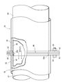
- FIG. 9 is an enlarged explanatory view of FIG. 8. It is an enlarged view of the connection part of an SCR inlet pipe and a urea mixing pipe. It is explanatory drawing of an exhaust-gas purification
- connection part of the SCR inlet pipe and urea mixing pipe which shows 11th Embodiment. It is an enlarged view of the connection part of the SCR inlet pipe and urea mixing pipe which shows 12th Embodiment. It is an enlarged view of the connection part of the SCR inlet pipe and urea mixing pipe which shows 13th Embodiment. It is an enlarged view of the connection part of the SCR inlet pipe and urea mixing pipe which shows 14th Embodiment. It is explanatory drawing of the connection part of the DPF exit pipe and urea mixing pipe which shows 15th Embodiment. FIG. 45 is an enlarged view of FIG. 44. It is explanatory drawing of the connection part of the DPF exit pipe and urea mixing pipe which shows 16th Embodiment. FIG. 47 is an enlarged view of FIG. 46.
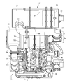
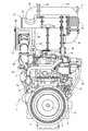
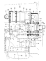
- FIG. 1 is a left side view in which an exhaust manifold of a diesel engine is installed
- FIG. 2 is a right side view in which an intake manifold of the diesel engine is installed
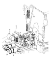
- FIG. 3 is a front view in which a cooling fan of the diesel engine is installed.
- the overall structure of the diesel engine 1 will be described with reference to FIGS.
- an intake manifold 3 is disposed on one side of the cylinder head 2 of the diesel engine 1.
- the cylinder head 2 is mounted on a cylinder block 5 in which an engine output shaft 4 (crankshaft) and a piston (not shown) are built.
- An exhaust manifold 6 is disposed on the other side of the cylinder head 2. The front end and the rear end of the engine output shaft 4 are projected from the front and rear surfaces of the cylinder block 5.
- a flywheel housing 8 is fixed to the rear surface of the cylinder block 5.
- a flywheel (not shown) is provided in the flywheel housing 8.
- the flywheel is pivotally supported on the rear end side of the engine output shaft 4.
- the power of the diesel engine 1 is taken out through the flywheel.
- an oil pan 11 is disposed on the lower surface of the cylinder block 5.
- the intake manifold 3 is provided with an exhaust gas recirculation device (EGR) 15 that takes in exhaust gas for recirculation.
- EGR exhaust gas recirculation device
- An air cleaner 16 shown in FIG. 4 is connected to the intake manifold 3. The external air that has been dedusted and purified by the air cleaner 16 is sent to the intake manifold 3 and supplied to each cylinder of the diesel engine 1.
- a cooling water pump 21 for circulating cooling water in the cylinder block 5 and the radiator 19 shown in FIG. 4 is provided.
- a cooling water pump 21 is disposed on the side of the diesel engine 1 where the cooling fan 24 is installed.
- the cooling water pump 21 and the cooling fan 24 are connected to the engine output shaft 4 via the V belt 22 and the like, and the cooling water pump 21 and the cooling fan 24 are driven. While the cooling water is sent from the cooling water pump 21 into the cylinder block 5 via the EGR cooler 18 of the exhaust gas recirculation device 15, the diesel engine 1 is cooled by the cooling fan 24 wind. .
- a first case 28 as a curate filter (DPF) and a second case 29 as a urea selective catalytic reduction (SCR) system for removing nitrogen oxides in exhaust gas of the diesel engine 1 are provided.
- DPF curate filter
- SCR selective catalytic reduction
- an oxidation catalyst 30 and a soot filter 31 are provided in the first case 28.
- the second case 29 includes an SCR catalyst 32 and an oxidation catalyst 33 for reducing urea selective catalyst.
- Exhaust gas discharged from each cylinder of the diesel engine 1 to the exhaust manifold 6 is discharged to the outside via the exhaust gas purification device 27 and the like.
- the exhaust gas purification device 27 is configured to reduce carbon monoxide (CO), hydrocarbons (HC), particulate matter (PM), and nitrogen oxides (NOx) in the exhaust gas of the diesel engine 1. is doing.
- 1st case 28 and 2nd case 29 are comprised in the elongate cylindrical shape extended long in the direction parallel to the output shaft (crankshaft) 4 of the diesel engine 1 by planar view (refer FIG. 9).
- a DPF inlet pipe 34 for taking in exhaust gas and a DPF outlet pipe 35 for discharging exhaust gas are provided on both sides of the first case 28 in the cylindrical shape (one end side and the other end side in the exhaust gas movement direction).
- an SCR inlet pipe 36 that takes in exhaust gas and an SCR outlet pipe 37 that discharges exhaust gas are provided on both sides of the second case 29 (one end side and the other end side in the exhaust gas movement direction).
- a supercharger 38 for forcibly sending air to the diesel engine 1 is arranged at the exhaust gas outlet of the exhaust manifold 6.
- the DPF inlet pipe 34 is communicated with the exhaust manifold 6 via the supercharger 38 to introduce the exhaust gas of the diesel engine 1 into the first case 28, while the SCR is connected to the DPF outlet pipe 35 via the urea mixing pipe 39.
- the inlet pipe 36 is connected, and the exhaust gas from the first case 28 is introduced into the second case 29.
- the DPF outlet pipe 35 and the urea mixing pipe 39 are connected to a bellows-like connecting pipe 41 that can be bent and stretched.
- the base end side of the pipe bracket 40 is fixed to the outer peripheral surface of the second case 29, and the SCR inlet pipe 36 and the urea mixing pipe 39 are detachably fixed by the pipe bracket 40.
- a common rail 43 and a fuel filter 44 are disposed on the intake manifold 3 installation side of the cylinder head 2, and a fuel pump 42 is disposed on the cylinder block 5 below the intake manifold 3.
- Each injector has an electromagnetic switching control type fuel injection valve (not shown).
- the common rail 43 is connected to the discharge side of the fuel pump 42, and the cylindrical common rail 43 is connected to each injector of the diesel engine 1.
- the surplus of the fuel pumped from the fuel pump 42 to the common rail 43 is returned to the fuel tank 45, high-pressure fuel is temporarily stored in the common rail 43, and the high-pressure fuel in the common rail 43 is used for each diesel engine 1. Supplied inside the cylinder.
- the fuel in the fuel tank 45 is pumped to the common rail 43 by the fuel pump 42, the high-pressure fuel is stored in the common rail 43, and the fuel injection valves of the injectors are controlled to open and close.
- the high-pressure fuel in 43 is injected into each cylinder of the diesel engine 1. That is, by electronically controlling the fuel injection valve of each injector, the fuel injection pressure, injection timing, and injection period (injection amount) can be controlled with high accuracy. Therefore, nitrogen oxides (NOx) discharged from the diesel engine 1 can be reduced.
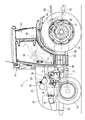
- FIG. 4 is a side view of the agricultural tractor
- FIG. 5 is a plan view thereof
- FIG. 6 is a left side view of the engine portion
- FIG. 7 is a right side view of the same portion
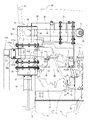
- FIG. 8 is a plan view of the same portion
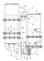
- FIG. 8 is an enlarged plan view of FIG.
- the left side in the forward direction of the tractor is simply referred to as the left side
- the right side in the forward direction is also simply referred to as the right side.
- a farm tractor 51 as a work vehicle supports a traveling machine body 52 with a pair of left and right front wheels 53 and a pair of left and right rear wheels 54.
- the engine 1 is mounted, and the diesel engine 1 is configured to travel forward and backward by driving the rear wheel 54 and the front wheel 53.
- the upper surface side and the left and right side surfaces of the diesel engine 1 are covered with an openable / closable bonnet 56.
- a cabin 57 on which an operator is boarded is installed behind the hood 56.
- a steering seat 58 on which an operator is seated and steering equipment such as a steering handle 59 as steering means are provided inside the cabin 57.
- a pair of left and right steps 60 for the operator to get on and off are provided in the left and right outer portions of the cabin 57, and fuel is supplied to the diesel engine 1 inside the step 60 and below the bottom portion of the cabin 57.
- a fuel tank 45 to be supplied is provided.
- the traveling machine body 52 includes a transmission case 61 for shifting the output from the diesel engine 1 and transmitting it to the rear wheels 54 (front wheels 53).
- a tiller working machine (not shown) is connected to the rear portion of the mission case 61 via a lower link 62, a top link 63, a lift arm 64, and the like so as to be movable up and down.
- a PTO shaft 65 for driving the tilling work machine and the like is provided on the rear side surface of the mission case 61.
- the traveling machine body 52 of the tractor 51 includes the diesel engine 1, a transmission case 61, a clutch case 66 that connects them, and the like.
- the DPF inlet pipe 34 is detachably bolted to the exhaust gas outlet pipe 80 of the supercharger 38.
- the upper end side of the DPF support leg 81 is welded and fixed to the outer peripheral surface of the end portion on the DPF outlet pipe 35 side in the outer peripheral surface of the first case 28, and the side surface of the cylinder head 2 or the upper surface of the exhaust manifold 6
- the bolt 82 is fastened to the lower end side of the DPF support leg 81 so as to be detachable. That is, the first case 28 is attached to the upper surface side of the diesel engine 1 through the exhaust gas outlet pipe 80 and the DPF support leg 81.
- the first case 28 is supported in parallel with the exhaust manifold 6 with the longitudinal direction of the cylindrical first case 28 facing the longitudinal direction of the diesel engine 1.
- an SCR first support leg 83 and an SCR second support leg 84 for supporting the second case 29 on the upper surface side of the diesel engine 1 are provided.
- the flange portion of the second case 29 is detachably bolted to the upper ends of the SCR first support leg 83 and the SCR second support leg 84, and the SCR is attached to the side surface of the cylinder head 2 or the upper surface of the intake manifold 3.
- the lower end sides of the first support leg 83 and the SCR second support leg 84 are detachably bolted.
- first case 28 and the second case 29 are arranged in parallel in the front-rear direction on the upper surface side of the diesel engine 1, and the first case 28 is located on the left side of the upper surface of the diesel engine 1, and the upper surface of the diesel engine 1.
- the second case 29 is located on the right side of the.
- a urea mixing tube 39 is disposed between the first case 28 and the second case 29 in parallel therewith.
- the first case 28, the second case 29, and the urea mixing pipe 39 are supported at a position higher than the cooling air path of the cooling fan 24, and the left and right sides of the urea mixing pipe 39 are the first case 28 and the second case. It is closed at 29.
- the temperature of the exhaust gas in the urea mixing pipe 39 is prevented from decreasing, and urea water supplied into the urea mixing pipe 39 is prevented from crystallizing.
- the urea water supplied into the urea mixing pipe 39 is configured to be mixed as ammonia in the exhaust gas from the first case 28 to the second case 29.
- a tail pipe 91 is erected on the front surface of the right corner of the cabin 57 of the front surface of the cabin 57, and a lower end side of the tail pipe 91 is extended inside the bonnet 56, so that the SCR outlet
- the lower end side of the tail pipe 91 is connected to the pipe 37, and the exhaust gas purified by the second case 29 is discharged from the tail pipe 91 toward the upper side of the cabin 57.
- a urea water tank 71 is installed on the left side of the bonnet 56 on the opposite side of the front side of the cabin 57 from the right side where the tail pipe 91 is disposed. That is, the tail pipe 91 is disposed on the right side of the rear part of the bonnet 56, and the urea water tank 71 is disposed on the left side of the rear part of the bonnet 56.
- a urea water tank 71 is mounted on the traveling machine body 52 (such as the bottom frame of the cabin 57) at the rear left side of the bonnet 56.
- An oil filling port 46 of the fuel tank 45 and a water filling port 72 of the urea water tank 71 are provided adjacent to each other at the lower front portion on the left side of the cabin 57.
- the tail pipe 91 is disposed on the front surface on the right side of the cabin 57 where the operator's boarding / alighting frequency is low, and the oil inlet 46 and the water inlet 72 are disposed on the front surface on the left side of the cabin 57 where the operator's boarding / alighting frequency is high.
- the cabin 57 is configured so that the operator can get on and off the control seat 58 from either the left side or the right side.
- a urea water injection pump 73 that pumps the urea aqueous solution in the urea water tank 71, an electric motor 74 that drives the urea water injection pump 73, and urea that is connected to the urea water injection pump 73 via a urea water injection pipe 75.
- a water injection nozzle 76 is provided.
- a urea water injection nozzle 76 is attached to the urea mixing pipe 39 via an injection base 77, and the urea aqueous solution is sprayed from the urea water injection nozzle 76 into the urea mixing pipe 39.
- the oxidation catalyst 30 and the soot filter 31 in the first case 28 reduce carbon monoxide (CO) and hydrocarbons (HC) in the exhaust gas of the diesel engine 1.
- urea water from the urea water injection nozzle 7 is mixed with the exhaust gas from the diesel engine 1 inside the urea mixing pipe 39.
- the SCR catalyst 32 and the oxidation catalyst 33 in the second case 29 reduce nitrogen oxides (NOx) in the exhaust gas mixed with urea water as ammonia, and are released from the tail pipe 91 to the outside of the machine. .
- a first case 28 for removing particulate matter in the exhaust gas of the diesel engine 1 and a second case 29 for removing nitrogen oxides in the exhaust gas of the diesel engine 1 are provided.
- the first case 28 and the second case 29 are arranged. Therefore, the first case 28 and the second case 29 are utilized by utilizing the upper surface side or the side surface of the diesel engine 1 so that the longitudinal directions of the first case 28 and the second case 29 are parallel to the output shaft 4 of the diesel engine 1.
- first case 28 and the second case 29 can be installed compactly. Further, the first case 28 and the second case 29 can be fixed to the upper surface side or side surface of the diesel engine 1 with high rigidity by a simple support structure provided on the upper surface side or side surface of the diesel engine 1. In addition, with respect to vibration of the diesel engine 1, the case 28, 29 can be maintained at a fixed interval between the first case 28 and the second case 29 and the outer shape is formed in a long cylindrical shape. Further, the exhaust gas piping between the exhaust gas outlet side of the diesel engine 1 and the tail pipe 91 can be simplified.
- a first case 28 is attached above the exhaust manifold 6 of the diesel engine 1 on the upper surface side of the diesel engine 1, and a second case 29 is located above the intake manifold 3 of the diesel engine 1. Is installed. Therefore, the upper surface side space of the diesel engine 1 can be effectively utilized, and the first case 28 and the second case 29 that are formed in a long cylindrical shape can be installed in a compact manner.
- the first case 28 and the second case 29 can be fixed to the upper surface side of the diesel engine 1 with high rigidity by a simple support structure that stands on the upper surface side of the diesel engine 1.
- a working vehicle having a driving cabin 57 disposed behind a hood 56 in which the diesel engine 1 is installed, and a fuel tank 45 provided below the driving cabin 57 and the diesel engine 1.
- a urea water tank 71 for exhaust gas purification is installed between them. Therefore, the urea water tank 71 can be heated by the exhaust heat of the diesel engine 1 and the fuel tank 45, the temperature of the aqueous solution in the urea water tank 71 can be maintained at a predetermined level or more, and the exhaust gas purification of the second case 29 can be performed in cold regions. It is possible to prevent the ability from decreasing.
- the fuel supply port of the fuel tank 45 and the water supply port of the urea water tank 71 can be disposed close to each other, the fuel supply work and the urea aqueous solution water supply work can be executed at the same work place, and the fuel or exhaust gas purification for the diesel engine 1 is performed. This makes it possible to improve the replenishment workability of the aqueous urea solution.
- a ring-shaped outlet side flange body 93 is fixed to the exhaust gas outlet side ends of the outer pipe 88 and the inner pipe 89.
- the inlet side flange body 92 and the outlet side flange body 93 are fastened and fixed by bolts 94 and nuts 95, and the SCR inlet pipe 36 and the urea mixing pipe 39 are connected.
- the outer tube 86 of the SCR inlet tube 36 and the outer tube 88 of the urea mixing tube 39 are formed of the same diameter pipe, and the inner tube 87 of the SCR inlet tube 36 and the urea mixing tube 39.
- the inner pipe 89 is also formed of a pipe having the same diameter.
- the pipe thickness of each inner pipe 87, 89 is made thinner than the pipe thickness of each outer pipe 86, 88.
- a fitting small-diameter portion 89 a is formed at the end of the inner tube 89 of the urea mixing tube 39 by drawing, and the fitting small-diameter portion 89 a is inserted into the inner tube 87 of the SCR inlet tube 36.
- the end portion of the inner tube 87 of the SCR inlet tube 36 to which the inlet side flange body 92 is fixed is attached to the end portion (the fitting small diameter portion 89a) of the inner tube 89 of the urea mixing tube 39 to which the outlet side flange body 93 is fixed. Fit.
- the exhaust gas in the urea mixing pipe 39 is configured to move to the SCR inlet pipe 36 without contacting the inner hole surface of the inlet side flange body 92 or the outlet side flange body 93.
- the exhaust gas comes into contact with the inner hole surface of the inlet-side flange body 92 or the outlet-side flange body 93, the temperature of the exhaust gas decreases and the urea component in the exhaust gas crystallizes, and the inlet-side flange body 92 Or, it adheres to the inner hole surface of the outlet side flange body 93, and a crystal lump of urea component is formed on the inner hole surface of the inlet side flange body 92 or the outlet side flange body 93, thereby causing a problem that hinders the movement of exhaust gas.
- the inlet-side flange body 92 or the outlet-side flange body 93 is formed by shielding the inner hole surface of the inlet-side flange body 92 or the outlet-side flange body 93 with the fitting small-diameter portion 89a.
- the exhaust gas is prevented from coming into contact with the inner hole surface, and the formation of a crystal block of urea component on the inner hole surface of the inlet side flange body 92 or the outlet side flange body 93 is prevented.
- the urea water injection direction 112 of the urea water injection nozzle 76 is set with respect to the cylindrical axis 111 of the cylindrical straight pipe portion 39b (the exhaust gas flow direction in the straight pipe portion 39b).
- the elbow pipe portion 39a is inclined to the lower side of the exhaust gas by a predetermined inclination angle 113 (about 4 degrees). That is, urea water is injected from the urea water injection nozzle 76 toward the inner wall surface 114a on the curved inner diameter side of the elbow pipe portion 39a in the inner wall surface 114 of the straight pipe portion 39b.
- the urea water injected from the urea water injection nozzle 76 is out of the curvature of the elbow pipe portion 39a in the inner wall surface 114 of the straight pipe portion 39b due to the discharge pressure of the exhaust gas moving from the elbow pipe portion 39a to the straight pipe portion 39b. It diffuses toward the inner wall surface 114b on the radial side and is mixed as ammonia in the exhaust gas.
- the first case 28 is attached to the upper surface side of the diesel engine 1, and the side of the diesel engine 1 on which the intake manifold 3, the exhaust gas recirculation device 15, the fuel filter 44, and the like are installed.
- the second case 29 is attached to the traveling machine body 52. That is, the second case 29 is attached to the traveling body 52 at the lower right side of the diesel engine 1, the second case 29 is disposed between the right front surface of the cabin 57 and the right front wheel 53, and urea mixing is performed above the diesel engine 1.
- a pipe 39 is extended in a transverse shape, and a tail pipe 91 is connected to the rear end side of the second case 29.
- the first case 28 is attached to the upper surface side of the diesel engine 1
- the second case 29 is attached to the side of the diesel engine 1 on the side where the intake manifold 3 is installed. Accordingly, the tail pipe 91 connected to the exhaust gas outlet side of the second case 29 and the second case 29 are brought close to each other on the side of the airframe (the right side of the airframe) on the side where the operator gets in and out of the tractor 51 or the like. Can be arranged compactly.
- the fuel tank 45 for the diesel engine 1 or the exhaust gas purifying is disposed on the other side of the airframe where the operator gets on and off frequently (the left side of the airframe away from the high temperature portion such as the tail pipe).
- the urea water tank 71 or the like can be provided to improve the replenishment workability of the fuel for the diesel engine 1 or the urea aqueous solution for exhaust gas purification.
- the second case 29 is arranged above the first case 28 on the side where the exhaust manifold 6 of the diesel engine 1 is installed.
- the first case 28 and the second case 29 are offset from the side of the diesel engine 1 on the left side opposite to the side where the intake manifold 3, exhaust gas recirculation device 15 and fuel filter 44 are installed.
- the second case 29 on the low temperature side (lower exhaust side), the urea mixing tube 39, and the like can be supported above the first case 28 on the high temperature side (upper exhaust side). 29 and the urea mixing pipe 39 can be reduced in temperature, and the exhaust gas purification function can be properly maintained.
- the second case 29 is disposed below the first case 28 on the side where the exhaust manifold 6 of the diesel engine 1 is installed.
- the second case 29 on the low temperature side (lower exhaust side) the urea mixing pipe 39 and the like can be supported.
- the second case 29 can be attached close to the fuel tank 45 or the urea water tank 71 to be mounted, and the bonnet height required for installing the first case 28 and the second case 29 can be formed low.
- the second case 29 when the second case 29 is arranged on the upper side or the lower side of the first case 28 on the side where the exhaust manifold 6 of the diesel engine 1 is installed, the exhaust of the diesel engine 1.
- the first case 28 and the second case 29 can be placed close to each other on the manifold 6 side in a compact manner. With the exhaust heat on the exhaust manifold 6 side of the diesel engine 1, the temperature of the first case 28 or the second case 29 can be easily maintained at the temperature required for exhaust gas purification.
- the exhaust gas movement direction of the first case 28 and the second case 29 is on the upper surface side of the diesel engine 1 so that it is parallel to the output shaft 4 (crankshaft) axis of the diesel engine 1.
- the exhaust gas moving direction of the first case 28 and the second case 29 is the output shaft 4 (crankshaft) shaft of the diesel engine 1.
- a first case 28 and a second case 29 are arranged on the upper surface side of the diesel engine 1 so as to be orthogonal to the core wire.
- an intake manifold 3 is disposed on one side of the cylinder head 2 of the diesel engine 1.
- the cylinder head 2 is mounted on a cylinder block 5 in which an engine output shaft 4 (crankshaft) and a piston (not shown) are built.
- An exhaust manifold 6 is disposed on the other side of the cylinder head 2. The front end and the rear end of the engine output shaft 4 are projected from the front and rear surfaces of the cylinder block 5.
- flywheel housing 8 is fixed to the rear surface of the cylinder block 5.
- a flywheel 9 is provided in the flywheel housing 8.
- a flywheel 9 is pivotally supported on the rear end side of the engine output shaft 4.
- the diesel engine 1 is configured to take out power through the flywheel 9.
- an oil pan 11 is disposed on the lower surface of the cylinder block 5.
- the intake manifold 3 is provided with an exhaust gas recirculation device (EGR) 15 for taking in exhaust gas for recirculation.
- EGR exhaust gas recirculation device
- An air cleaner 16 is connected to the intake manifold 3. The external air that has been dedusted and purified by the air cleaner 16 is sent to the intake manifold 3 and supplied to each cylinder of the diesel engine 1.
- a cooling water pump 21 that circulates cooling water in the cylinder block 5 and the radiator 19 is disposed on the cooling fan 24 installation side of the diesel engine 1.
- the cooling water pump 21 and the cooling fan 24 are connected to the engine output shaft 4 via the V belt 22 and the like, and the cooling water pump 21 and the cooling fan 24 are driven. While the cooling water is sent from the cooling water pump 21 into the cylinder block 5, the diesel engine 1 is cooled by the cooling fan 24 wind.
- a first case 28 as a curate filter (DPF case) and a second case 29 as a urea selective catalytic reduction system (SCR case) for removing nitrogen oxides in the exhaust gas of the diesel engine 1 are provided.
- DPF case curate filter
- SCR case urea selective catalytic reduction system
- an oxidation catalyst 30 and a soot filter 31 are provided in the first case 28.
- the second case 29 includes an SCR catalyst 32 and an oxidation catalyst 33 for reducing urea selective catalyst.
- Exhaust gas discharged from each cylinder of the diesel engine 1 to the exhaust manifold 6 is discharged to the outside via the exhaust gas purification device 27 and the like.
- the exhaust gas purification device 27 is configured to reduce carbon monoxide (CO), hydrocarbons (HC), particulate matter (PM), and nitrogen oxides (NOx) in the exhaust gas of the diesel engine 1. is doing.
- the first case 28 and the second case 29 are configured in a substantially cylindrical shape extending long in the horizontal direction perpendicular to the output shaft (crankshaft) 4 of the diesel engine 1 in plan view.
- a DPF inlet pipe 34 for taking in exhaust gas and a DPF outlet pipe 35 for discharging exhaust gas are provided on both cylindrical sides of the first case 28 (one end side and the other end side in the exhaust gas movement direction).
- an SCR inlet pipe 36 for taking in the exhaust gas and an SCR outlet pipe 37 for discharging the exhaust gas are provided on both cylindrical sides of the second case 29 (one end side and the other end side in the exhaust gas moving direction).
- a supercharger 38 for forcibly sending air to the diesel engine 1 is arranged at the exhaust gas outlet of the exhaust manifold 6.
- the DPF inlet pipe 34 communicates with the exhaust manifold 6 via the supercharger 38 to introduce the exhaust gas of the diesel engine 1 into the first case 28, while the DPF outlet pipe 35 enters the SCR inlet via the urea mixing pipe 39.
- the pipe 36 is connected, and the exhaust gas of the first case 28 is introduced into the second case 29.
- the exhaust gas outlet side of the end of the urea mixing pipe 39 is detachably connected to the SCR inlet pipe 36 via the pipe bracket 40.
- a fuel pump 42 for connecting a fuel tank 45 and a common rail 43 are provided to each injector (not shown) for multiple cylinders of the diesel engine 1.
- a common rail 43 and a fuel filter 44 are disposed on the intake manifold 3 installation side of the cylinder head 2, and a fuel pump 42 is disposed on the cylinder block 5 below the intake manifold 3.
- Each injector has an electromagnetic switching control type fuel injection valve (not shown).
- the common rail 43 is connected to the discharge side of the fuel pump 42, and the cylindrical common rail 43 is connected to each injector of the diesel engine 1. It is connected.
- the fuel in the fuel tank 45 is pumped to the common rail 43 by the fuel pump 42, high-pressure fuel is stored in the common rail 43, and the fuel injection valves of the injectors are controlled to open and close.
- the high-pressure fuel inside is injected into each cylinder of the diesel engine 1. That is, by electronically controlling the fuel injection valve of each injector, the fuel injection pressure, injection timing, and injection period (injection amount) can be controlled with high accuracy. Therefore, nitrogen oxides (NOx) discharged from the diesel engine 1 can be reduced.
- NOx nitrogen oxides
- a cabin 57 on which an operator is boarded is installed behind the hood 56.
- a steering seat 58 on which an operator is seated and steering equipment such as a steering handle 59 as steering means are provided inside the cabin 57.
- a pair of left and right steps 60 for the operator to get on and off are provided in the left and right outer portions of the cabin 57, and fuel is supplied to the diesel engine 1 inside the step 60 and below the bottom portion of the cabin 57.
- a fuel tank 45 to be supplied is provided.
- the exhaust gas exhaust structure of the diesel engine 1 will be described with reference to FIG. 1, FIG. 3, FIG.
- one end of a flexible heat-resistant rubber gas discharge pipe 171 is connected to the exhaust gas outlet pipe 80 of the supercharger 38, and the other end of the gas discharge pipe 171 is connected to the DPF inlet pipe 34.
- the first case 28 is connected to the supercharger 38 via the gas discharge pipe 171, and the exhaust gas of the exhaust manifold 6 is moved from the supercharger 38 to the first case 28. .
- a metal bellows-like connecting pipe 41 is connected to the DPF outlet pipe 35, and the other end side of the bellows-like connecting pipe 41 is connected to the exhaust gas inlet side of the urea mixing pipe 39 (the elbow pipe in FIGS. 11 and 18).
- Part 39a) is integrally disposed, and the DPF outlet pipe 35 is connected to one end side of the urea mixing pipe 39 via the bellows-like connecting pipe 41, and the exhaust gas outlet side of the urea mixing pipe 39 (FIGS. 11 and 18).
- the SCR inlet pipe 36 is connected via a pipe bracket 40 to the straight pipe portion 39b).
- the SCR inlet pipe 36 is connected to the DPF outlet pipe 35 via the bellows-like connecting pipe 41 and the urea mixing pipe 39
- the second case 29 is connected to the first case 28, and the second case 29 is connected to the second case 29.
- the case 29 is configured to move the exhaust gas.
- the bellows-like connecting pipe 41 is formed in a bellows shape so as to be foldable and extendable. When the first case 28 and the second case 29 are assembled, the bellows-like connecting pipe 41 is deformed to form the first bellows-like connecting pipe 41. An assembly dimension error between the case 28 and the second case 29 is corrected.
- the urea water tank 71 for storing urea water, the urea water injection nozzle 76 for supplying urea, and the urea water in the urea water tank 71 are pumped to the urea water injection nozzle 76.
- a urea water injection pump 73 is provided.
- the urea water tank 71 is installed in the traveling machine body 52 between the diesel engine 1 and the fuel tank 45.
- the urea water injection pump 73 is driven by the output of the electric motor 74.
- the urea water injection nozzle 76 is disposed on the injection base 77 of the urea mixing tube 39.
- the urea water in the urea water tank 71 is pumped from the urea water injection pump 73 to the urea water injection nozzle 76, the urea water is injected from the urea water injection nozzle 76 into the urea mixing pipe 39, and the urea mixing pipe
- the urea water from the urea water injection nozzle 7 is mixed with the exhaust gas from the diesel engine 1 inside 39.
- the exhaust gas mixed with urea water passes through the second case 29 (SCR catalyst 32, oxidation catalyst 33), nitrogen oxides (NOx) in the exhaust gas are reduced, and discharged from the SCR outlet pipe 37 to the outside.
- a first support leg 181 that supports the DPF inlet pipe 34 side of the first case 28 and a second support leg 182 that supports the DPF outlet pipe 35 side of the first case 28 are provided.
- the lower end side of the first support leg 181 is fastened to the side face of the cylinder head 2 on the exhaust manifold 6 arrangement side, and the first support leg 181 is erected on one side face of the cylinder head 2.
- the DPF inlet pipe 34 side of the first case 28 is detachably fixed to the upper end side of the first support leg 181 with a fastening band 186.
- a radiator 19 is provided so as to face the cooling fan 24.
- a body frame 191 is erected on the upper surface side of the traveling body 52.
- the body frame 191 supports the radiator 19 and the wind tunnel plate 192.
- the cooling fan 24 is covered by the wind tunnel plate 192, the cooling fan 24 sucks outside air through the radiator 19, and supplies cooling air from the cooling fan 24 to the diesel engine 1 by the guidance of the wind tunnel plate 192.
- Cooling water is circulated by the cooling water pump 21 to each part of the diesel engine 1 and the radiator 19 to cool the diesel engine 1.
- the SCR support leg 193 protrudes from the second case 29 toward the lower surface, and the lower end side of the SCR support leg 193 is detachably fastened to the body frame 191 with a bolt 194. is doing.
- a second case 29 is disposed substantially immediately above the cooling fan 24.
- a wind tunnel plate 192 as a shroud is interposed between the upper surface side of the cooling fan 24 and the lower surface side of the second case 29.
- the upper ends of the first support leg 181 and the second support leg 182 are provided at a higher position than the uppermost end of the wind tunnel plate 192, and the first case 28 is positioned higher than the uppermost end of the wind tunnel plate 192.
- the second case 29 is supported at a higher position than the first case 28 via the body frame 191 and the SCR support leg 193.
- the second case 29 is extended in the left-right direction.
- the first case 28 and the second case 29 are arranged in parallel on the upper surface side of the cooling fan 24 installation portion, and urea is disposed above the opposing side surface of the first case 28 and the second case 29.
- Mixing tubes 39 are extended in parallel.
- first case 28 and the second case 29 are arranged at a higher position than the cooling fan 24 air passage of the diesel engine 1 formed by the wind tunnel plate 192, and the first case 28 and the second case 29 are arranged at a higher position than the first case 28.
- Two cases 29 are arranged. That is, the first case 28 and the second case 29 are disposed at a position higher than the upper surface of the wind tunnel plate 192 (cooling fan shroud) of the diesel engine 1, and the second case 29 is disposed immediately above the cooling fan 24.
- the cooling air from the cooling fan 24 is guided to the upper surface side of the diesel engine 1 by the engine cooling air guide action of the first support leg 181 and the second support leg 182 as case brackets.
- a cooling wind guide body (not shown) is provided between the first case 28 and the wind tunnel plate body 92, and the cooling wind guide body is guided from the wind tunnel plate body 192 side toward the upper surface side of the diesel engine 1.
- the cooling air from the cooling fan 24 can also be moved.
- the first case 28 for removing particulate matter in the exhaust gas of the diesel engine 1, and the diesel engine 1 A second case 29 for removing nitrogen oxides in the exhaust gas, and a urea mixing pipe 39 for connecting the exhaust gas outlet of the first case 28 to the exhaust gas inlet of the second case 29.
- the two cases 29 are arranged in parallel and the urea water is injected into the urea mixing pipe 39, the first case 28, the second case 29, and the urea mixing pipe 39 are arranged in the exhaust gas moving direction.
- the DPF outlet pipe 35 as an exhaust gas outlet pipe is provided on the end face of the first case 28 on the exhaust gas outlet side, and the exhaust gas inlet is provided on the side surface of the second case 29 on the exhaust gas inlet side.
- tube The SCR inlet pipe 36 is provided, and the DPF outlet pipe 35 is connected to the urea mixing pipe 39 via the bellows-like connecting pipe 41, and the urea water injection nozzle 76 is provided between the urea mixing pipe 39 and the bellows-like connecting pipe 41. Is arranged. Therefore, the assembly operation of the first case 28 and the assembly operation of the second case 29 are respectively performed on the diesel engine 1 or the vehicle (the traveling machine body 52), and the first case 28 and the second case 29 are separately performed.
- the urea mixing tube 39 can be connected to the first case 28 and the second case 29 via the bellows-like connecting pipe 41 in a state where the case 29 is assembled independently.
- urea water injected from the urea water injection nozzle 76 is bellows-like by injecting urea water from the urea water injection nozzle 76 toward the urea mixing pipe 39 on the lower side of the exhaust gas movement of the bellows-shaped connecting pipe 41. It can prevent that it adheres to the inner surface of the connection pipe 41, and crystallizes.
- the position of the DPF inlet pipe 34 is aligned with the exhaust gas outlet pipe 80, and the second case 29 is provided on the exhaust gas inlet side of the first case 28.
- the first case 28 and the second case 29 can be arranged within the front-rear width of the diesel engine 1 by being displaced.
- the first embodiment modified example shown in FIG. 12
- the fifth embodiment FIGS.
- an exhaust gas outlet pipe as an exhaust connection pipe for taking in the exhaust gas of the diesel engine 1 80 is connected to the side surface of the first case 28 on the exhaust gas inlet side, and the second case 29 is displaced to the exhaust gas outlet side of the first case 28 to end the end surface of the first case 28 on the exhaust gas outlet side. Further, the end face of the second case 29 on the exhaust gas outlet side protrudes by an installation width dimension L of the bellows-like connection pipe 41, and the bellows-like connection pipe 41 is provided on the outer peripheral side of the second case 29 on the exhaust gas outlet side. Can also be arranged. Therefore, the exhaust gas can be supplied to both the first case 28 and the second case 29 from the respective side surfaces, and the diffusion of the exhaust gas inside each of the first case 28 and the second case 29 can be secured satisfactorily.
- the second case 29 is displaced with respect to the first case 28 in the exhaust gas movement direction, and the difference between the lengths of the first case 28 and the second case 29 in the exhaust gas movement direction and the bellows-like connection
- the exhaust gas inlet side end surface of the second case 29 is positioned on the lower side of the exhaust gas movement with respect to the exhaust gas inlet side end surface of the first case 28 by the step size M of the mounting width generated by the installation width dimension L of the pipe 41.
- the exhaust gas outlet side end surface of the second case 29 is located on the lower side of the exhaust gas movement with respect to the exhaust gas outlet side end surface of the first case 28 by the installation width dimension L of the bellows-like connecting pipe 41. It is deviated.
- the second case 29 is displaced to the exhaust gas outlet side of the first case 28, and the end surface of the second case 29 on the exhaust gas outlet side is more exhaust gas than the end surface of the first case 28 on the exhaust gas outlet side. Since it protrudes on the moving lower side, the urea mixing tube 39 and the bellows-like connecting pipe 41 can be compactly supported inside a rectangular frame (plan view) surrounding the first case 28 and the second case 29.
- the bellows-like connecting pipe 41 is brought close to the exhaust gas outlet side end surface of the first case 28 and the side surface of the second case 29, so that the exhaust gas outlet side end surface of the first case 28 and the side surface of the second case 29
- the bellows-like connecting pipe 41 can be installed in the formed recess space, the temperature drop of the bellows-like connecting pipe 41 can be reduced, and the temperature of the exhaust gas from the first case 28 to the urea mixing pipe 39 It can be easily prevented from lowering when passing. Therefore, even if urea water flows backward into the bellows-like connection pipe 41, crystallization of urea water inside the bellows-like connection pipe 41 can be prevented.
- the outer tube 86 of the SCR inlet tube 36 and the outer tube 88 of the urea mixing tube 39 are formed of the same diameter pipe, and the inner tube 87 of the SCR inlet tube 36 and the inner tube 88 of the urea mixing tube 39 are formed.
- the pipe 89 is also formed of a pipe having the same diameter. The pipe thickness of each inner pipe 87, 89 is made thinner than the pipe thickness of each outer pipe 86, 88.
- the end portion of the inner tube 89 of the urea mixing tube 39 is welded and fixed to the inner hole surface of the outlet side flange body 93, and one end side of the small diameter tube 90 is fitted to the end portion of the inner tube 89 of the urea mixing tube 39.
- the other end of the fitting small-diameter pipe 90 is inserted into the inner pipe 87 of the SCR inlet pipe 36 by welding.
- the exhaust gas in the urea mixing pipe 39 is configured to move to the SCR inlet pipe 36 without contacting the inner hole surface of the inlet side flange body 92 or the outlet side flange body 93.
- the exhaust gas comes into contact with the inner hole surface of the inlet-side flange body 92 or the outlet-side flange body 93, the temperature of the exhaust gas decreases and the urea component in the exhaust gas crystallizes, and the inlet-side flange body 92 Or, it adheres to the inner hole surface of the outlet side flange body 93, and a crystal lump of urea component is formed on the inner hole surface of the inlet side flange body 92 or the outlet side flange body 93, thereby causing a problem that hinders the movement of exhaust gas.
- the inner flange surface of the inlet side flange body 92 or the outlet side flange body 93 is shielded by the fitting small-diameter pipe 90, whereby the inlet side flange body 92 or the outlet side flange body 93 is covered.
- the exhaust gas is prevented from coming into contact with the inner hole surface, and the formation of a crystal block of urea component on the inner hole surface of the inlet side flange body 92 or the outlet side flange body 93 is prevented.
- a urea mixing pipe 39 that injects urea water into the exhaust gas of the diesel engine 1 and an exhaust gas purification case that removes nitrogen oxides in the exhaust gas of the diesel engine 1.
- SCR as an exhaust gas inlet pipe of the second case 29 at the outlet of the urea mixing pipe 39 via the pipe bracket 40 (inlet side flange body 92, outlet side flange body 93) as a flange body.
- the outer pipe 86 of the SCR inlet pipe 36 having the double pipe structure and the outer pipe 88 of the urea mixing pipe 39 having the double pipe structure are disposed at the exhaust gas inlet side end portions of the inner pipe 87.
- the exhaust pipe outlet side end of the inner pipe 89 is connected, and a fitting small diameter part 89a (fitting small diameter pipe 90) is formed at the end of the inner pipe 89 of the urea mixing pipe 39, so that the inner pipe of the SCR inlet pipe 36 is formed.
- a fitting small diameter part 89a (fitting small diameter pipe 90) is inserted inside, exhaust gas is formed on the inner hole surface of the pipe bracket 40 (inlet side flange body 92, outlet side flange body 93).
- the outer tube 86 of the SCR inlet tube 36 and the outer tube 88 of the urea mixing tube 39 are formed of the same diameter pipe, and the inner tube 87 of the SCR inlet tube 36 and the urea mixing tube. Since the inner pipe 89 is formed of a pipe having the same diameter, a change in the flow resistance of the exhaust gas moving from the urea mixing pipe 39 to the SCR inlet pipe 36 can be suppressed, and the exhaust gas can be moved smoothly. be able to.
- the pipe thickness of the inner pipe 89 of the urea mixing pipe 39 is made thinner than the pipe thickness of the outer pipe 88 of the urea mixing pipe 39. Drawing or the like for forming the fitting small-diameter portion 89a at the end of the inner tube 89 can be easily performed. The manufacturing cost of the urea mixing tube 39 can be reduced.
- the first case 28 of the seventh embodiment is configured in a horizontally long long cylindrical shape extending long in a direction parallel to the output shaft (crankshaft) 4 of the diesel engine 1 in plan view.
- a DPF inlet pipe 34 for taking in exhaust gas and a DPF outlet pipe 35 for discharging exhaust gas are provided on both sides of the first case 28 in the cylindrical shape (one end side and the other end side in the exhaust gas movement direction).
- the 2nd case 29 is comprised in the vertically long elongate cylindrical shape extended long in the up-down direction.
- an SCR inlet pipe 36 for taking in the exhaust gas and an SCR outlet pipe 37 for discharging the exhaust gas are provided.
- the SCR inlet pipe 36 and the urea mixing pipe 39 are detachably fixed by a pipe bracket 40.
- the DPF inlet pipe 34 is detachably bolted to the exhaust gas outlet pipe 80 of the supercharger 38.
- the upper end side of the DPF support leg 81 is fastened and fixed to the outer peripheral surface of the end portion on the DPF outlet pipe 35 side of the outer peripheral surface of the first case 28, and on the side surface of the cylinder head 2 or the upper surface of the exhaust manifold 6.
- the bolt 82 is fastened to the lower end side of the DPF support leg 81 so as to be detachable. That is, the first case 28 is attached to the upper surface side of the diesel engine 1 through the exhaust gas outlet pipe 80 and the DPF support leg 81.
- the first case 28 is supported in parallel with the exhaust manifold 6 with the longitudinal direction of the cylindrical first case 28 facing the longitudinal direction of the diesel engine 1.
- the second case 29 is supported on the traveling machine body frame 120 that constitutes the cabin 57.
- a pair of left and right purification case supports 121 are integrally fixed to the traveling machine body frame 120 by welding, and a pair of left and right purification case supports 121 are projected from the traveling machine body frame 120 toward the front.
- the back support bracket 122 is integrally welded and fixed to the back side of the second case 29, and the second case 29 is directed rearward from the middle portion of the vertical width. The back support bracket 122 is projected.
- An upper bolt 126a and a lower bolt are fitted between the pair of left and right purification case supports 121 and screwed to the left and right sides of the pair of left and right purification case supports 121 and the rear support bracket 122 from the left and right directions.
- the back support bracket 122 is detachably fastened to the purification case support 121 by 126b.
- the upper bolt 126a is removably engaged with the engagement notch 121a of the purification case support 121, and the lower bolt 126b is inserted into the position adjusting long hole 121b of the purification case support 121.
- the upper bolt 126 a is temporarily fixed to the back support bracket 122, the second case 29 is brought close to the mounting position of the purification case support 121, and the purification case support 121 is engaged.
- the upper bolt 126a is engaged with the notch 121a, and the second case 29 is temporarily fixedly supported by the purification case support 121.
- the lower bolt 126b is passed through the position adjusting long hole 121b of the purification case support 121, the lower bolt 126b is fastened to the back support bracket 122, and the upper bolt 126a is fastened to the back support bracket 122.
- the rear support bracket 122 is detachably fixed to the purification case support 121, and the second case 29 is mounted on the front side of the cabin 57 (operating unit) via the traveling machine body frame 120.
- the first case 28 is horizontally disposed in the front-rear direction (horizontal posture) on the upper surface side of the diesel engine 1, while the second case 29 is positioned in the vertically long posture on the right side of the rear portion of the diesel engine 1.
- a urea mixing tube 39 is arranged in parallel with the first case 28.
- the first case 28 and the urea mixing pipe 39 are supported at a position higher than the cooling air passage of the cooling fan 24 on the upper surface of the diesel engine 1.
- the temperature of the exhaust gas in the urea mixing pipe 39 is prevented from decreasing, and urea water supplied into the urea mixing pipe 39 is prevented from crystallizing.
- the urea water supplied into the urea mixing pipe 39 is configured to be mixed as ammonia in the exhaust gas from the first case 28 to the second case 29.
- a tail pipe 91 is erected on the front surface of the right corner of the cabin 57 among the front surfaces of the cabin 57, and the lower end side of the tail pipe 91 is directed toward the lower end side of the second case 29.
- the lower end side of the tail pipe 91 is connected to the SCR outlet pipe 37 on the lower end side of the second case 29, and the exhaust gas purified in the second case 29 is discharged from the tail pipe 91 toward the upper side of the cabin 57. Is done.
- a urea water tank 71 is installed on the left side of the bonnet 56 on the opposite side of the front side of the cabin 57 from the right side where the tail pipe 91 is disposed.
- the tail pipe 91 is disposed on the right side of the rear part of the bonnet 56, and the urea water tank 71 is disposed on the left side of the rear part of the bonnet 56. Further, a urea water tank 71 is mounted on the traveling machine body 52 (the traveling machine body frame 120 on which the cabin 57 is supported) on the rear left side of the bonnet 56.
- the pipe bracket 40 that connects the SCR inlet pipe 36 and the urea mixing pipe 39 includes an inlet side flange body 92 disposed on the exhaust gas inlet side of the SCR inlet pipe 36, and the exhaust gas from the urea mixing pipe 39. It has an outlet side flange body 93 disposed on the gas outlet side.
- the inlet side flange body 92 is welded and fixed to the exhaust gas inlet side end portions of the outer pipe 86 and the inner pipe 87 of the SCR inlet pipe 36 having a double pipe structure, and the outer pipe 88 of the urea mixing pipe 39 having a double pipe structure;
- Outlet end flange body 93 is welded and fixed to the end portion of exhaust gas outlet side of outer pipe 88 of urea mixing tube 39 among the end portion of exhaust pipe outlet side of inner tube 89.
- the gasket 90 is sandwiched between the inlet side flange body 92 and the outlet side flange body 93, and the inlet side flange body 92 and the outlet side flange body 93 are fastened and fixed by bolts 94 and nuts 95.
- the gasket 90 is sandwiched and fixed between the flange bodies 93 to connect the SCR inlet pipe 36 and the urea mixing pipe 39.
- the outer pipe 86 of the SCR inlet pipe 36 and the outer pipe 88 of the urea mixing pipe 39 are formed of the same diameter pipe, and the urea mixing pipe 39 has an inner diameter dimension of the inner pipe 87 of the SCR inlet pipe 36.
- the outer diameter of the inner pipe 89 is made smaller, the inner pipes 87 and 89 are formed of pipes of different diameters, and the urea mixing pipe 39 is connected to the exhaust gas inlet side end of the inner pipe 87 of the SCR inlet pipe 36. An end portion on the exhaust gas outlet side of the inner pipe 89 is inserted.
- a ring-shaped thin plate support 84 that connects the outer peripheral surface of the inner tube 89 to the inner peripheral surface of the outer tube 88 of the urea mixing tube 39 is provided at the exhaust gas outlet side end of the urea mixing tube 39.
- the ring-shaped outer peripheral side of the thin plate support 84 is welded and fixed to the inner peripheral surface of the outer tube 88 of the urea mixing tube 39, and the ring-shaped inner peripheral side of the thin plate support 84 is fixed to the outer peripheral surface of the inner tube 89 of the urea mixing tube 39. The welding is fixed.
- a gap between the outer tube 88 and the inner tube 89 of the urea mixing tube 39 is formed at a constant interval by the thin plate support 84.
- pipe 87,89 is formed thinly.
- the exhaust gas outlet side end portion of the inner pipe 87 of the SCR inlet pipe 36 is fitted into the end portion of the inner pipe 89 of the urea mixing tube 39 so that the exhaust gas in the urea mixing pipe 39 is fed into the inlet port. It is configured to move to the SCR inlet pipe 36 without contacting the inner hole surface of the side flange body 92 or the outlet side flange body 93.
- the inlet side flange body 92 or the outlet side flange body 93 easily radiates heat.
- the inner pipe 89 can prevent the exhaust gas from coming into contact with the inner hole surface of the inlet side flange body 92 or the outlet side flange body 93, and urea components can be prevented from contacting the inner hole surface of the inlet side flange body 92 or the outlet side flange body 93. Formation of crystal lumps can be prevented.
- a first case 28 for removing particulate matter in the exhaust gas of the diesel engine 1 and a second case 29 for removing nitrogen oxides in the exhaust gas of the diesel engine 1 are provided.
- the first case 28 is supported by the diesel engine 1
- the second case 29 is attached via the support body 121. Therefore, it is not necessary to secure an installation space for the second case 29 in the engine room (bonnet 56), the bonnet 56 (engine room) in which the diesel engine 1 is installed can be configured compactly, and the traveling machine body frame 120 can be configured.
- the second case 29 can be easily supported, and the assembling workability or maintenance workability of the cases 28 and 29 formed in a long cylindrical shape can be improved. Further, while the temperature drop of the second case 29 due to the cooling air of the engine 1 can be suppressed, the exhaust gas outlet of the first case 28 and the exhaust gas inlet of the second case 29 are spaced at intervals necessary for mixing urea. It can be separated and the generation of ammonia in the exhaust gas reaching the second case 29 can be promoted.
- the second case 29 is attached to the traveling body frame 120 on one side of the rear portion of the diesel engine 1 through the purification case support 121 in a vertically long posture. Therefore, the second case 29 formed in a cylindrical shape with a long outer shape can be installed compactly near the rear part of the diesel engine 1 (near the joint corner of the hood 56 and the cabin 57 as the operating part). For example, even in a structure in which the left and right widths of the bonnet 56 are limited so that the front wheels can be visually observed, the operator's front view from the cabin 57 (operating unit) can be easily secured.
- a work vehicle is provided with a cabin 57 as a driving unit on which an operator rides behind a hood 56 in which the diesel engine 1 is installed, and the fuel provided in the lower portion of the cabin 57
- a urea water tank 71 for purifying exhaust gas is installed between the tank 45 and the diesel engine 1
- a second case 29 is disposed on one side of the rear part of the diesel engine 1
- urea is disposed on the other side of the rear part of the diesel engine 1.
- a water tank 71 is arranged.
- the fuel filling port 46 (fuel filling port) of the fuel tank 45 and the water filling port 72 (water filling port) of the urea water tank 71 can be arranged close to each other, and the fuel supply work and the urea aqueous solution water supply work are executed at the same work place.
- the installation space for the second case 29 and the urea water tank 71 both sides of the rear part of the diesel engine 1 ( The front lower part of the cabin 57 can be used effectively.
- the urea water tank 71 can be heated by the exhaust heat of the diesel engine 1 and the fuel tank 45, the aqueous solution temperature in the urea water tank 71 can be maintained at a predetermined level or more, and the exhaust gas of the second case 29 in a cold district or the like. It is possible to prevent the purification capacity from being lowered.
- the first case 28 is attached to the upper surface side of the diesel engine 1 via the DPF support leg 81, and the intake manifold 3 and the exhaust gas recirculation device 15 among the rear side of the diesel engine 1 and
- the second case 29 is detachably fastened to the purification case support 121 of the traveling machine body frame 120 on the side where the fuel filter 44 and the like are installed. That is, the second case 29 is configured in a horizontally long elongated cylindrical shape that extends long in the left-right direction.
- the second case 29 is attached to the traveling body frame 120 at the lower right side of the rear portion of the diesel engine 1 in a horizontally long posture, and the second case 29 in a horizontally long posture is disposed between the right front surface of the cabin 57 and the right front wheel 53, and the diesel engine.
- a urea mixing tube 39 is extended to the rear, a urea mixing tube 39 is connected to the left end side of the second case 29, and a tail pipe 91 is connected to the right end side of the second case 29.
- the second case 29 is attached to the traveling machine body frame 120 on one side of the rear portion of the diesel engine 1 through the purification case support 121 in a horizontally long posture.
- the outer case is formed in a long cylindrical shape, and the second case 29 can be installed compactly.
- the second case 29 is easily disposed at a lower position on the front side of the cabin 57 in the right outside of the rear part of the bonnet 56.
- the operator's front view from the cabin 57 can be easily secured.
- the exhaust gas movement directions (cylindrical shaft centers) of the first case 28 and the second case 29 are set with respect to the output shaft 4 of the diesel engine 1 extending in the front-rear direction.
- the first case 28 and the second case 29 are extended in the left-right direction so as to be orthogonal to each other.
- the first case 28 and the second case 29 are arranged in parallel on the upper surface side of the cooling fan 24 installation portion of the upper surface side of the diesel engine 1, and the urea mixing tube 39 is interposed between the first case 28 and the second case 29. It extends in parallel.
- the first case 28 and the second case 29 are arranged at a higher position than the cooling fan 24 air passage of the diesel engine 1.
- the first case 28 and the second case 29 are arranged on the traveling machine body 52 on which the air cleaner 16 is installed.
- the first case 28 and the second case 29 are supported by the traveling machine body 52 ahead of the radiator 19.
- the first case 28 and the second case 29 are formed in a long cylindrical shape extending long in a direction parallel to the output shaft (crankshaft) 4 of the diesel engine 1 in plan view.
- a urea mixing tube 39 is disposed between the first case 28 and the second case 29 in parallel therewith.
- the second case 29 can be attached close to the traveling machine body 52, and the bonnet height required for installing the first case 28 and the second case 29 can be formed low.
- the outer peripheral surface of the inner tube 89 is connected to the inner peripheral surface of the convex ring-shaped projecting support 88a, and a gap between the outer tube 88 and the inner tube 89 of the urea mixing tube 39 is formed at regular intervals by the projecting support 88a. is doing.
- pipe 87,89 is formed thinly.
- the inner hole surface of the inlet side flange body 92 or the outlet side flange body 93 is shielded by the exhaust gas outlet side end portion of the inner pipe 89 of the urea mixing pipe 39, thereby
- the inner pipe 89 can prevent the exhaust gas from coming into contact with the inner hole surface of the flange body 92 or the outlet side flange body 93, and the urea mass crystal block is formed on the inner hole surface of the inlet side flange body 92 or the outlet side flange body 93. Can be prevented.
- a connection structure of the SCR inlet pipe 36 as the exhaust gas inlet pipe and the urea mixing pipe 39 will be described.
- a heat insulating support 84 is provided to connect the outer peripheral surface of the inner tube 89 to the inner peripheral surface of the outer tube 88 of the urea mixing tube 39.
- the glass wool filler is formed into a ring shape to form the heat insulating support 84.
- the ring-shaped outer periphery of the heat insulating support 84 is crimped to the inner peripheral surface of the outer tube 88 of the urea mixing tube 39, and the ring-shaped inner periphery of the heat insulating support 84 is bonded to the outer peripheral surface of the inner tube 89 of the urea mixing tube 39. Crimp the sides. A gap between the outer tube 88 and the inner tube 89 of the urea mixing tube 39 is formed at a constant interval by the heat insulating support 84.
- the inner hole surface of the inlet side flange body 92 or the outlet side flange body 93 is shielded by the exhaust gas outlet side end portion of the inner pipe 89 of the urea mixing pipe 39. Further, the inner pipe 89 can prevent the exhaust gas from coming into contact with the inner hole surface of the inlet side flange body 92 or the outlet side flange body 93, and the urea component can be formed on the inner hole surface of the inlet side flange body 92 or the outlet side flange body 93. Can be prevented from being formed.
- a urea mixing pipe 39 that injects urea water into the exhaust gas of the diesel engine 1 and an exhaust gas that removes nitrogen oxides in the exhaust gas of the diesel engine 1.
- an engine apparatus including a second case 29 as a purification case and connecting an SCR inlet pipe 36 as an exhaust gas inlet pipe of the second case 29 to an outlet of the urea mixing pipe 39 via flange bodies 92 and 93.
- the outer tube 88 of the double tube structure 39 and the exhaust gas outlet side end of the inner tube 89 are connected to the outer tube 86 of the SCR inlet tube 36 and the inner tube 87 of the tube structure.
- the exhaust gas inlet side end portion of the inner pipe of the SCR inlet pipe 36 is fitted on the exhaust gas outlet side end portion of the inner pipe 89 of the urea mixing pipe 39 and the outer pipe of the urea mixing pipe 39. 88 of its inner tube 89 Since the gas gas outlet side end portion is supported, the inner hole surfaces of the flange bodies 92 and 93 can be shielded by the exhaust gas outlet side end portion of the inner pipe 89 of the urea mixing pipe 39, and the flange body. It is possible to prevent exhaust gas from coming into contact with the inner hole surfaces of 92 and 93 and to prevent formation of a crystal lump of urea component on the inner hole surfaces of the flange bodies 92 and 93, but with excellent heat insulation. In addition, the connection structure between the exhaust gas inlet pipe 36 having a double pipe structure and the urea mixing pipe 39 can be simplified.
- a support body 84 that connects the outer peripheral surface of the inner tube 89 to the inner peripheral surface of the outer tube 88 of the urea mixing tube 39 at the end on the exhaust gas outlet side of the urea mixing tube 39. , 85, 88a. Accordingly, the mounting interval between the outer tube 88 and the inner tube 89 of the urea mixing tube 39 can be properly maintained by the supports 84, 85, 88a, and the supports 84, 85, By forming 88a, the exhaust gas outlet side end shape of the urea mixing tube 39 can be easily formed. In addition, while the urea mixing tube 39 can be configured at a low cost, the rigidity of the urea mixing tube 39 can be improved by the support.
- the inner diameter of the inner pipe 87 of the SCR inlet pipe 36 is made larger than the outer diameter of the inner pipe 89 of the urea mixing pipe 39, and the inlet side as a flange body is formed.
- An outer pipe 86 and an inner pipe 87 of the SCR inlet pipe 36 are fixed to the flange body 92, and an outer pipe 88 of the urea mixing pipe 39 is fixed to the outlet side flange body 93 as a flange body, and the inlet side flange body 92 and the outlet side are fixed.
- the flange body 93 is configured to be fastened.
- the outer tube 86 and the inner tube 87 of the SCR inlet tube 36 and the outer tube 88 and the inner tube 89 of the urea mixing tube 39 can be easily combined with the inlet side flange body 92 and the outlet side flange body 93, and the SCR inlet
- the connection workability between the pipe 36 and the urea mixing pipe 39 can be improved, and the strength of the connecting portion between the SCR inlet pipe 36 and the urea mixing pipe 39 can be easily secured.
- connection structure between the SCR inlet pipe 36 and the urea mixing pipe 39 in the thirteenth embodiment will be described.
- the arrangement structure of the first case 28 and the second case 29 and the structure of the urea mixing pipe 39 are the same as the arrangement structure of the first case 28 and the second case 29 of the seventh embodiment, and the urea mixing pipe 39. This is the same as the structure of the part.
- the pipe bracket 40 connecting the SCR inlet pipe 36 and the urea mixing pipe 39 includes an inlet side flange body 92 disposed on the exhaust gas inlet side of the SCR inlet pipe 36, and an exhaust gas outlet of the urea mixing pipe 39. It has an outlet side flange body 93 disposed on the side.
- the outer pipe 86 and the inner pipe 87 of the SCR inlet pipe 36 of the double pipe structure are bent outward at the exhaust gas inlet side end portions, and ring-shaped sandwiching piece portions 86c, 87c at the exhaust gas inlet side end portions thereof.
- the exhaust gas outlet side end portions of the outer tube 88 and the inner tube 89 of the urea mixing tube 39 having a double-pipe structure are bent outward, and a ring is attached to the exhaust gas outlet side end portion thereof.
- Shaped clamping piece portions 88c and 89c are formed.
- the sandwiching piece portions 86c, 87c, 88c, 89c and the gasket 90 are sandwiched between the inlet side flange body 92 and the outlet side flange body 93, and the inlet side flange body 92 and the outlet side flange body 93 are connected with bolts 94 and nuts 95.
- the clamping piece portions 86c, 87c, 88c, 89c and the gasket 90 are clamped and fixed between the inlet side flange body 92 and the outlet side flange body 93, and the SCR inlet pipe 36 and the urea mixing pipe 39 are connected.
- the outer tube 86 of the SCR inlet tube 36 and the outer tube 88 of the urea mixing tube 39 are formed of the same diameter pipe, and the inner tube 87 of the SCR inlet tube 36 and the inner tube 89 of the urea mixing tube 39 are also formed. It is formed with pipes of the same diameter.
- the pipe thickness of each inner pipe 87, 89 is made thinner than the pipe thickness of each outer pipe 86, 88.
- the exhaust gas in the urea mixing pipe 39 is configured to move to the SCR inlet pipe 36 without contacting the inner hole surface of the inlet side flange body 92 or the outlet side flange body 93.
- the exhaust gas comes into contact with the inner hole surface of the inlet-side flange body 92 or the outlet-side flange body 93, the temperature of the exhaust gas decreases and the urea component in the exhaust gas crystallizes, and the inlet-side flange body 92 Or, it adheres to the inner hole surface of the outlet side flange body 93, and a crystal lump of urea component is formed on the inner hole surface of the inlet side flange body 92 or the outlet side flange body 93, thereby causing a problem that hinders the movement of exhaust gas.
- the inlet side flange body 92 or the outlet side flange body 93 is shielded by the sandwiching piece portions 86 c, 87 c, 88 c, and 89 c so as to shield the inlet side flange body 92.
- the sandwiching piece portions 86 c, 87 c, 88 c, and 89 c so as to shield the inlet side flange body 92.
- the exhaust gas inlet side end portions of the outer tube 86 and the inner tube 87 of the SCR inlet tube 36 are bent outward, and ring-shaped holding pieces 86c, 87c, and the exhaust gas outlet side end portions of the outer tube 88 and the inner tube 89 of the urea mixing tube 39 are bent outward, and ring-shaped holding pieces 88c, 89c is formed. Therefore, the outer side pipe 86 and the inner pipe 87 of the SCR inlet pipe 36, and the outer pipe 88 and the inner pipe 89 of the urea mixing pipe 39 are connected to the inlet side flange body 92 via the sandwiching pieces 86c, 87c, 88c, 89c.
- the SCR inlet pipe 36 and urea mixing pipe 39 which can be sandwiched and fixed by the outlet flange body 93 and improved in heat insulation (heat retaining property) by a double pipe structure, for example, with a connection structure that reduces welding labor and the like. Can be easily linked.
- the pipe bracket 40 connecting the SCR inlet pipe 36 and the urea mixing pipe 39 includes an inlet side flange body 92 disposed on the exhaust gas inlet side of the SCR inlet pipe 36, and an exhaust gas outlet of the urea mixing pipe 39. It has an outlet side flange body 93 disposed on the side.
- the exhaust gas inlet side end of the inner pipe 87 of the SCR inlet pipe 36 of the double pipe structure is bent outward to form a ring-shaped sandwiching piece 87c at the exhaust gas inlet side end thereof, and the same
- the end portion on the exhaust gas outlet side of the inner tube 89 of the urea mixing tube 39 having a double-pipe structure is bent outward to form a ring-shaped clamping piece portion 89c at the end portion on the exhaust gas outlet side.
- the exhaust gas inlet side end of the outer pipe 86 of the SCR inlet pipe 36 having a double pipe structure is bent inward to form a ring-shaped contact piece 86d at the exhaust gas inlet side end thereof.
- the exhaust gas outlet side end portion of the outer pipe 88 of the urea mixing tube 39 having a double-pipe structure is bent inward, and a ring-shaped contact piece portion is formed at the exhaust gas outlet side end portion thereof. 88d is formed.
- the end faces of the contact pieces 86d, 88d of the outer tubes 86, 88 are brought into contact with the outer peripheral surfaces of the inner tubes 87, 89, and the inlet side flange body 92 is provided on the outer tube 86 of the SCR inlet tube 36.
- the outlet flange body 93 is fixed by welding to the outer pipe 88 of the urea mixing pipe 39.
- the sandwiching pieces 87c and 89c and the gasket 90 are sandwiched between the inlet side flange body 92 and the outlet side flange body 93, and the inlet side flange body 92 and the outlet side flange body 93 are fastened and fixed with bolts 94 and nuts 95. Then, the sandwiching pieces 87c and 89c and the gasket 90 are sandwiched and fixed between the inlet side flange body 92 and the outlet side flange body 93, and the SCR inlet pipe 36 and the urea mixing pipe 39 are connected.
- the outer tube 86 of the SCR inlet tube 36 and the outer tube 88 of the urea mixing tube 39 are formed of the same diameter pipe, and the inner tube 87 of the SCR inlet tube 36 and the inner tube 89 of the urea mixing tube 39 are also formed. It is formed with pipes of the same diameter.
- the pipe thickness of each inner pipe 87, 89 is made thinner than the pipe thickness of each outer pipe 86, 88.
- the exhaust gas in the urea mixing pipe 39 is configured to move to the SCR inlet pipe 36 without contacting the inner hole surface of the inlet side flange body 92 or the outlet side flange body 93.
- the exhaust gas comes into contact with the inner hole surface of the inlet-side flange body 92 or the outlet-side flange body 93, the temperature of the exhaust gas decreases and the urea component in the exhaust gas crystallizes, and the inlet-side flange body 92 Or, it adheres to the inner hole surface of the outlet side flange body 93, and a crystal lump of urea component is formed on the inner hole surface of the inlet side flange body 92 or the outlet side flange body 93, thereby causing a problem that hinders the movement of exhaust gas.
- the inlet-side flange body 92 or the outlet-side flange body 92 or the outlet-side flange body 93 or the outlet-side flange body 93 is shielded by the clamping pieces 87c and 89c. It is possible to prevent the exhaust gas from coming into contact with the inner hole surface of the body 93 by the sandwiching piece portions 87c and 89c, and the urea component crystal lump is formed on the inner hole surface of the inlet side flange body 92 or the outlet side flange body 93. Can be prevented.
- the SCR inlet pipe 36 as the exhaust gas inlet pipe of the second case 29 is connected to the outlet of the urea mixing pipe 39 through the inlet side flange body 92 as the flange body and the outlet side flange body 93 (pipe bracket 40).
- the outer tube 88 of the SCR inlet tube 36 having a double tube structure and the exhaust gas inlet side end portion of the inner tube 87 are exhausted from the outer tube 88 and the inner tube 89 of the urea mixing tube 39 having a double tube structure.
- the gas outlet side end is connected and the exhaust gas inlet side end of the inner pipe 87 of the SCR inlet pipe 36 is bent outward to form a ring-shaped holding piece 87c at the exhaust gas inlet side end. You Together, it is bent toward the exhaust gas outlet side end portion of the inner tube 89 of the urea mixing tube 39 to the outside, to form a ring-shaped clamping piece portions 89c on the exhaust gas outlet side end portion. Therefore, the inlet side flange body 92 and the outlet side flange body 93 can be disposed on the outer peripheral side of the inner pipe 89 of the urea mixing pipe 39 (the inner pipe 87 of the SCR inlet pipe 36).
- the exhaust piece By shielding the inner hole surface of each of the sandwiching piece portions 87c and 89c, the exhaust piece contacts the inner hole surfaces of the inlet side flange body 92 and the outlet side flange body 93 with each of the sandwiching piece portions 87c and 89c. Therefore, it is possible to prevent the formation of a crystal lump of urea components on the inner hole surfaces of the inlet side flange body 92 and the outlet side flange body 93.
- the exhaust gas inlet side end of the outer pipe 86 of the SCR inlet pipe 36 or the exhaust gas outlet side end of the outer pipe 88 of the urea mixing pipe 39 is bent inward to contact pieces. 86d or contact piece 88d is formed, and the end of contact piece 86d or the end of contact piece 88d is brought into contact with the outer peripheral surface of each of the inner pipes 87 and 89. Accordingly, the inner pipes 87 and 89 can be positioned and connected at the end portions of the contact pieces 86d and 88d of the outer pipes 86 and 88, and the outer pipes 86 and 88 and the inner pipes 87 and 89 are connected to each other.
- the distance between the SCR inlet pipe 36 and the urea mixing pipe 39 can be easily improved while the distance between the SCR inlet pipe 36 and the urea mixing pipe 39 can be improved. .
- the arrangement structure of the first case 28 and the second case 29 and the connection structure between the SCR inlet pipe 36 and the urea mixing pipe 39 are the same as those of the first case 28 and the second case 29 of the fifteenth embodiment.
- the arrangement structure is the same as the connection structure of the SCR inlet pipe 36 and the urea mixing pipe 39.
- the urea mixing pipe 39 includes an elbow pipe portion 39a connected to the bellows-like connecting pipe 41 and a long cylindrical straight pipe connected to the SCR inlet pipe 36 via the pipe bracket 40. It has a part 39b.
- the injection base 77 is welded and fixed to the elbow pipe part 39a in the vicinity where the elbow pipe part 39a and the straight pipe part 39b are joined, and the urea water injection nozzle 76 is opened from the elbow pipe part 39a toward the inner hole of the straight pipe part 39b.
- the urea water injection direction of the urea water injection nozzle 76 with respect to the cylindrical axis 111 of the cylindrical straight pipe portion 39b (the exhaust gas flow direction in the straight pipe portion 39b).
- 112 is inclined by a predetermined inclination angle 113 (about 2 to 20 degrees, for example, about 12 degrees, about 8 degrees, about 4 degrees, etc.) to the exhaust gas lower side of the elbow pipe section 39a, and the central axis ( The urea water is injected from the urea water injection nozzle 76 toward the inner side of the elbow pipe portion 39a with respect to the cylindrical axis 111).
- the injection port 76a of the urea water injection nozzle 76 is disposed at a position displaced by a certain positional displacement dimension 115 closer to the bending outer side than the cylindrical axis 111 (center axis) of the straight pipe part 39b, and the elbow pipe part
- the urea water injection nozzle 76 is disposed outside the bent side of 39a, and the inner wall surface 114a near the boundary between the bent inner side of the elbow pipe part 39a and the start end side of the straight pipe part 39b is formed on the inner wall surface 114a on the straight pipe part 39b side.
- a nozzle hole 76a of the urea water injection nozzle 76 is formed so as to be able to inject urea water.
- urea water is injected from the injection port 76a of the urea water injection nozzle 76 toward the inner wall surface 114a on the curved inner diameter side of the elbow pipe portion 39a in the inner wall surface 114 of the straight pipe portion 39b.
- the urea water jetted from the nozzle port 76a of the urea water jet nozzle 76 is the elbow pipe part 39a in the inner wall surface 114 of the straight pipe part 39b due to the exhaust gas discharge pressure moving from the elbow pipe part 39a to the straight pipe part 39b.
- ammonia is hydrolyzed into the exhaust gas supplied to the second case 29 by hydrolysis of urea water. As mixed.
- the inclination angle 113 (urea water injection direction 112) of the urea water injection nozzle 76 with respect to the cylindrical axis 111 of the straight pipe portion 39b is the inner diameter of the elbow pipe portion 39a and the straight pipe portion 39b, or standard work (diesel engine 1).
- the operation is performed based on the exhaust gas flow velocity at the rated rotation of the engine). For example, when the inclination angle 113 is excessive, urea water adheres to the inner wall surface 114a on the curved inner diameter side of the elbow pipe portion 39a, and urea tends to crystallize on the inner wall surface 114a on the curved inner diameter side.
- the injection port 76a of the urea water injection nozzle 76 is disposed on the inner peripheral surface of the elbow pipe portion 39a on the curved outer diameter side.
- the cylindrical axis 111 of the straight pipe portion 39b of the inner peripheral surface of the elbow pipe portion 39a on the bending outer side (curved outer diameter side).
- a receding surface 114c on the curved outer diameter side is formed at an inner circumferential surface (inner circumferential surface on the curved outer diameter side) closer to the bending outer side than the (center axis), and the nozzle hole 76a of the urea water injection nozzle 76 is formed on the receding surface 114c.
- the injection base 77 is fixed to the receding surface 114c and the urea water injection nozzle 76 is attached, and the straight pipe of the inner wall surface 114a near the boundary between the bent inner side of the elbow pipe part 39a and the start end side of the straight pipe part 39b.
- the injection port 76a of the urea water injection nozzle 76 is opened toward the inner wall surface 114a on the side of the portion 39b. That is, the exhaust gas flow pressure that supports the injection port 76a of the urea water injection nozzle 76 on the curved outer diameter receding surface 114c formed in the elbow pipe part 39a and moves in the elbow pipe part 39a is directly applied to the injection port 76a. It has been reduced to act on.
- a urea mixing pipe 39 for injecting urea water into the exhaust gas of the diesel engine 1 and a second exhaust gas purification case for removing nitrogen oxides in the exhaust gas of the diesel engine 1
- the urea mixing pipe 39 includes a case 29, and the urea mixing pipe 39 is an engine device having an elbow pipe part 39 a for introducing exhaust gas from the diesel engine 1 and a straight pipe part 39 b for leading exhaust gas to the second case 29.
- a urea water injection nozzle 76 for injecting urea water toward the bent inner side of the elbow pipe part 39a with respect to the cylindrical axis line 111 (center axis line) of the straight pipe part 39b and bent more than the cylindrical axis line 111 of the straight pipe part 39b.
- An injection port 76a of the urea water injection nozzle 76 is disposed at a position displaced toward the outside. Therefore, the urea water scattering direction from the nozzle port 76a of the urea water injection nozzle 76 and the cylindrical axis 111 of the straight pipe portion 39b can be easily matched, and the inner peripheral surface of the elbow pipe portion 39a or the straight pipe portion 39b.
- the amount of urea water adhering to can be reduced.
- the injection port 76a of the urea water injection nozzle 76 is opened at a position displaced by a certain positional deviation dimension 115 toward the bending outer side of the cylindrical axis 111 of the straight pipe portion 39b, the rotation of the engine 1 is reduced.
- the amount of urea water injected toward the inner side of the elbow pipe portion 39a can be reduced, and urea water is formed on the inner peripheral surface of the elbow pipe portion 39a or the straight pipe portion 39b. It can suppress adhering.
- a urea water injection nozzle 76 is disposed outside the elbow pipe portion 39a, and urea water is directed toward the boundary between the bent inner side of the elbow pipe portion 39a and the start end side of the straight pipe portion 39b.
- the nozzle hole 76a of the urea water injection nozzle 76 is formed. Therefore, even if the flow rate or flow rate of the exhaust gas varies, the urea water injection position can be maintained at a substantially constant position of the central axis (cylindrical axis 111) of the straight pipe portion 39b, and formation of a urea crystal lump is easy. Can be prevented.
- the outer peripheral surface of the straight pipe portion 39b is bent to the inner peripheral surface position closer to the outer side of the bend than the central axis (cylindrical axis 111).
- a diameter-side receding surface 114c is formed, and the nozzle port 76a of the urea water injection nozzle 76 is supported on the receding surface 114c.
Landscapes
- Engineering & Computer Science (AREA)
- Chemical & Material Sciences (AREA)
- General Engineering & Computer Science (AREA)
- Mechanical Engineering (AREA)
- Combustion & Propulsion (AREA)
- Chemical Kinetics & Catalysis (AREA)
- Health & Medical Sciences (AREA)
- Toxicology (AREA)
- Exhaust Gas After Treatment (AREA)
Abstract
Description
29 第2ケース(排気ガス浄化ケース)
36 SCR入口管(排気ガス入口管)
39 尿素混合管
39a エルボ管部
39b 直管部
40 パイプブラケット(フランジ体)
76 尿素水噴射ノズル
76a 噴口
84 薄板支持体
85 断熱性支持体
86 SCR入口管の外管
87 SCR入口管の内管
88 尿素混合管の外管
88a 凸リング状突起形支持体
89 尿素混合管の内管
89a 内管の嵌合小径部
90 嵌合小径管
92 入口側フランジ(フランジ体)
93 出口側フランジ(フランジ体)
111 直管部の円筒軸心線(中心軸線)
114c 湾曲外径側の後退面
Claims (9)
- エンジンの排気ガス中に尿素水を噴射する尿素混合管と、前記エンジンの排気ガス中の窒素酸化物質を除去する排気ガス浄化ケースを備え、フランジ体を介して前記尿素混合管の出口に前記排気ガス浄化ケースの排気ガス入口管を接続するエンジン装置において、
二重管構造の前記排気ガス入口管の外管と内管の排気ガス入口側端部に、二重管構造の前記尿素混合管の外管と内管の排気ガス出口側端部を接続させると共に、前記尿素混合管の内管の端部に嵌合小径部を形成し、前記排気ガス入口管の内管の内部に嵌合小径部を内挿させるように構成したことを特徴とするエンジン装置。 - 前記排気ガス入口管の外管と前記尿素混合管の外管を、同一径のパイプにて形成すると共に、前記排気ガス入口管の内管と前記尿素混合管の内管を、同一径のパイプにて形成したことを特徴とする請求項1に記載のエンジン装置。
- 前記尿素混合管の外管のパイプ肉厚みに比べ、前記尿素混合管の内管のパイプ肉厚みを薄く形成したことを特徴とする請求項1に記載のエンジン装置。
- エンジンの排気ガス中に尿素水を噴射する尿素混合管と、前記エンジンの排気ガス中の窒素酸化物質を除去する排気ガス浄化ケースを備え、フランジ体を介して前記尿素混合管の出口に前記排気ガス浄化ケースの排気ガス入口管を接続するエンジン装置において、
二重管構造の前記排気ガス入口管の外管と内管の排気ガス入口側端部に、二重管構造の前記尿素混合管の外管と内管の排気ガス出口側端部を接続させる構造であって、前記尿素混合管の内管の排気ガス出口側端部に、前記排気ガス入口管の内管の排気ガス入口側端部を被嵌させると共に、前記尿素混合管の外管にその内管の排気ガス出口側端部を支持させるように構成したことを特徴とするエンジン装置。 - 前記尿素混合管の排気ガス出口側端部において、前記尿素混合管の外管の内周面に内管の外周面を連結させる支持体を設けたことを特徴とする請求項4に記載のエンジン装置。
- 前記尿素混合管の内管の外径寸法に比べ、前記排気ガス入口管の内管の内径寸法を大きく形成すると共に、フランジ体としての入口側フランジ体に前記排気ガス入口管の外管と内管を固着し、フランジ体としての出口側フランジ体に前記尿素混合管の外管を固着し、前記入口側フランジ体と出口側フランジ体を締結するように構成したことを特徴とする請求項4に記載のエンジン装置。
- エンジンの排気ガス中に尿素水を噴射する尿素混合管と、前記エンジンの排気ガス中の窒素酸化物質を除去する排気ガス浄化ケースを備え、フランジ体を介して尿素混合管の出口に排気ガス浄化ケースの排気ガス入口管を接続するエンジン装置において、
二重管構造の前記排気ガス入口管の外管と内管の排気ガス入口側端部に、二重管構造の前記尿素混合管の外管と内管の排気ガス出口側端部を接続させると共に、前記排気ガス入口管の内管の排気ガス入口側端部を外側に向けて折り曲げて、その排気ガス入口側端部にリング状の挟持片部を形成すると共に、前記尿素混合管の内管の排気ガス出口側端部を外側に向けて折り曲げて、その排気ガス出口側端部にリング状の挟持片部を形成したことを特徴とするエンジン装置。 - 前記排気ガス入口管の外管と内管の排気ガス入口側端部を外側に向けて折り曲げて、それらの排気ガス入口側端部にリング状の挟持片部を形成すると共に、前記尿素混合管の外管と内管の排気ガス出口側端部を外側に向けて折り曲げて、それらの排気ガス出口側端部にリング状の挟持片部を形成したことを特徴とする請求項7に記載のエンジン装置。
- 前記排気ガス入口管の外管の排気ガス入口側端部、または前記尿素混合管の外管の排気ガス出口側端部を、内側に向けて折り曲げて内管の外周面に当接させたことを特徴とする請求項7に記載のエンジン装置。
Priority Applications (6)
| Application Number | Priority Date | Filing Date | Title |
|---|---|---|---|
| EP14776490.6A EP2980382B1 (en) | 2013-03-28 | 2014-03-26 | Exhaust device |
| KR1020217039700A KR20210152008A (ko) | 2013-03-28 | 2014-03-26 | 엔진 장치 |
| CN201480018082.0A CN105051344B (zh) | 2013-03-28 | 2014-03-26 | 发动机装置 |
| KR1020157023960A KR20150133706A (ko) | 2013-03-28 | 2014-03-26 | 엔진 장치 |
| US14/779,626 US9556770B2 (en) | 2013-03-28 | 2014-03-26 | Engine device |
| KR1020207004457A KR20200019781A (ko) | 2013-03-28 | 2014-03-26 | 엔진 장치 |
Applications Claiming Priority (8)
| Application Number | Priority Date | Filing Date | Title |
|---|---|---|---|
| JP2013069570A JP5876851B2 (ja) | 2013-03-28 | 2013-03-28 | エンジン装置 |
| JP2013069571A JP2014190330A (ja) | 2013-03-28 | 2013-03-28 | エンジン装置 |
| JP2013-069571 | 2013-03-28 | ||
| JP2013069569A JP2014190328A (ja) | 2013-03-28 | 2013-03-28 | エンジン装置 |
| JP2013-069569 | 2013-03-28 | ||
| JP2013069568A JP6091288B2 (ja) | 2013-03-28 | 2013-03-28 | エンジン装置 |
| JP2013-069568 | 2013-03-28 | ||
| JP2013-069570 | 2013-03-28 |
Publications (1)
| Publication Number | Publication Date |
|---|---|
| WO2014157286A1 true WO2014157286A1 (ja) | 2014-10-02 |
Family
ID=51624251
Family Applications (1)
| Application Number | Title | Priority Date | Filing Date |
|---|---|---|---|
| PCT/JP2014/058431 Ceased WO2014157286A1 (ja) | 2013-03-28 | 2014-03-26 | エンジン装置 |
Country Status (5)
| Country | Link |
|---|---|
| US (1) | US9556770B2 (ja) |
| EP (1) | EP2980382B1 (ja) |
| KR (3) | KR20200019781A (ja) |
| CN (1) | CN105051344B (ja) |
| WO (1) | WO2014157286A1 (ja) |
Cited By (2)
| Publication number | Priority date | Publication date | Assignee | Title |
|---|---|---|---|---|
| WO2017078011A1 (ja) * | 2015-11-06 | 2017-05-11 | ヤンマー株式会社 | 作業車両 |
| JP2020106076A (ja) * | 2018-12-27 | 2020-07-09 | 株式会社クボタ | 作業車 |
Families Citing this family (19)
| Publication number | Priority date | Publication date | Assignee | Title |
|---|---|---|---|---|
| JP5975859B2 (ja) * | 2012-11-29 | 2016-08-23 | ヤンマー株式会社 | エンジン装置 |
| JP6343119B2 (ja) * | 2013-03-15 | 2018-06-13 | ヤンマー株式会社 | コンバインのエンジン装置 |
| JP6066787B2 (ja) * | 2013-03-15 | 2017-01-25 | ヤンマー株式会社 | コンバインのエンジン装置 |
| JP6240784B2 (ja) * | 2013-12-19 | 2017-11-29 | ボルボ トラック コーポレイション | 自動車のシャーシ上に取り付けられる排ガス処理システム |
| JP6297905B2 (ja) * | 2014-04-22 | 2018-03-20 | 日立建機株式会社 | 建設機械 |
| JP6275552B2 (ja) * | 2014-05-29 | 2018-02-07 | ヤンマー株式会社 | 作業車両 |
| EP2985166B1 (en) * | 2014-08-14 | 2017-08-02 | CNH Industrial Italia S.p.A. | Exhaust system for an off-road vehicle |
| CN104903135B (zh) * | 2014-08-19 | 2017-06-23 | 株式会社小松制作所 | 作业车辆 |
| US10308108B2 (en) | 2015-03-30 | 2019-06-04 | Kubota Corporation | Working machine |
| US9879581B2 (en) * | 2016-03-25 | 2018-01-30 | Caterpillar Inc. | After-treatment system |
| JP6504138B2 (ja) * | 2016-09-08 | 2019-04-24 | トヨタ自動車株式会社 | 内燃機関の排気構造 |
| JP6737741B2 (ja) * | 2017-06-15 | 2020-08-12 | ヤンマーパワーテクノロジー株式会社 | エンジン |
| JP2019011684A (ja) * | 2017-06-29 | 2019-01-24 | いすゞ自動車株式会社 | 排気ガス浄化システム |
| DE102017130866A1 (de) * | 2017-12-21 | 2019-06-27 | Faurecia Emissions Control Technologies, Germany Gmbh | Abgasanlage für einen Verbrennungsmotor eines Kraftfahrzeugs sowie Kraftfahrzeug |
| DE102018107768A1 (de) * | 2018-04-03 | 2019-10-10 | Eberspächer Exhaust Technology GmbH & Co. KG | Mischerbaugruppe |
| JP6979593B2 (ja) * | 2019-03-22 | 2021-12-15 | ヤンマーパワーテクノロジー株式会社 | エンジン |
| CN110185518A (zh) * | 2019-05-24 | 2019-08-30 | 安徽江淮汽车集团股份有限公司 | 后处理集成装置及柴油机 |
| US11415083B1 (en) | 2021-07-09 | 2022-08-16 | Caterpillar Inc. | Engine systems and methods |
| CN113883351B (zh) * | 2021-10-28 | 2026-01-02 | 北京胜能能源科技有限公司 | 一种多路接头及电池液冷系统 |
Citations (10)
| Publication number | Priority date | Publication date | Assignee | Title |
|---|---|---|---|---|
| JPS52102511U (ja) * | 1976-01-30 | 1977-08-04 | ||
| JPS5453121U (ja) * | 1977-09-21 | 1979-04-12 | ||
| JPH06212967A (ja) * | 1993-01-14 | 1994-08-02 | Sumitomo Metal Ind Ltd | 断熱性に優れた管セグメント |
| JP2000051930A (ja) * | 1998-08-11 | 2000-02-22 | Mazda Motor Corp | 2重管、その製造方法及び2重管の製造に使用する型部材 |
| JP2000248931A (ja) * | 1999-02-26 | 2000-09-12 | Toyota Motor Corp | 内燃機関の排気管 |
| JP2001132872A (ja) * | 1999-11-08 | 2001-05-18 | Mazda Motor Corp | 二重パイプ構造及びその製造方法 |
| JP2005226528A (ja) * | 2004-02-12 | 2005-08-25 | Tokyo Roki Co Ltd | Scrマフラー |
| JP2006322343A (ja) | 2005-05-17 | 2006-11-30 | Nissan Diesel Motor Co Ltd | エンジンの排気浄化装置及びこれに用いられる排気管の構造 |
| JP2009114910A (ja) | 2007-11-05 | 2009-05-28 | Denso Corp | 排気浄化装置 |
| JP2012127311A (ja) | 2010-12-17 | 2012-07-05 | Ud Trucks Corp | 還元剤の拡散器 |
Family Cites Families (11)
| Publication number | Priority date | Publication date | Assignee | Title |
|---|---|---|---|---|
| JPH0828257A (ja) * | 1994-07-11 | 1996-01-30 | Toyota Motor Corp | 二重排気管 |
| DE19856366C1 (de) * | 1998-12-07 | 2000-04-20 | Siemens Ag | Vorrichtung und Verfahren zum Nachbehandeln von Abgasen einer mit Luftüberschuß arbeitenden Brennkraftmaschine |
| JP2000282858A (ja) | 1999-03-31 | 2000-10-10 | Suzuki Motor Corp | エンジンの排気管 |
| JP4989062B2 (ja) * | 2005-04-28 | 2012-08-01 | バブコック日立株式会社 | 流体混合装置 |
| KR101004741B1 (ko) * | 2006-01-06 | 2011-01-06 | 미쯔이 죠센 가부시키가이샤 | 배 가스의 탈초방법 및 장치 |
| JP2007198225A (ja) | 2006-01-25 | 2007-08-09 | Calsonic Kansei Corp | 排気二重管 |
| JP2009085050A (ja) | 2007-09-28 | 2009-04-23 | Denso Corp | 添加剤噴射弁、添加剤噴射装置、及び排気浄化システム |
| JP2011516770A (ja) * | 2008-02-29 | 2011-05-26 | エミテック ゲゼルシヤフト フユア エミツシオンス テクノロギー ミツト ベシユレンクテル ハフツング | 少なくとも1つの還元剤前駆体および/または還元剤を含むガスを生成するための蒸発装置 |
| US8225602B2 (en) * | 2009-06-11 | 2012-07-24 | Stanadyne Corporation | Integrated pump and injector for exhaust after treatment |
| JP2012002085A (ja) * | 2010-06-14 | 2012-01-05 | Daimler Ag | 排気流通管の構造 |
| US8938954B2 (en) * | 2012-04-19 | 2015-01-27 | Donaldson Company, Inc. | Integrated exhaust treatment device having compact configuration |
-
2014
- 2014-03-26 US US14/779,626 patent/US9556770B2/en not_active Expired - Fee Related
- 2014-03-26 CN CN201480018082.0A patent/CN105051344B/zh not_active Expired - Fee Related
- 2014-03-26 KR KR1020207004457A patent/KR20200019781A/ko not_active Ceased
- 2014-03-26 KR KR1020217039700A patent/KR20210152008A/ko not_active Ceased
- 2014-03-26 WO PCT/JP2014/058431 patent/WO2014157286A1/ja not_active Ceased
- 2014-03-26 EP EP14776490.6A patent/EP2980382B1/en not_active Not-in-force
- 2014-03-26 KR KR1020157023960A patent/KR20150133706A/ko not_active Ceased
Patent Citations (10)
| Publication number | Priority date | Publication date | Assignee | Title |
|---|---|---|---|---|
| JPS52102511U (ja) * | 1976-01-30 | 1977-08-04 | ||
| JPS5453121U (ja) * | 1977-09-21 | 1979-04-12 | ||
| JPH06212967A (ja) * | 1993-01-14 | 1994-08-02 | Sumitomo Metal Ind Ltd | 断熱性に優れた管セグメント |
| JP2000051930A (ja) * | 1998-08-11 | 2000-02-22 | Mazda Motor Corp | 2重管、その製造方法及び2重管の製造に使用する型部材 |
| JP2000248931A (ja) * | 1999-02-26 | 2000-09-12 | Toyota Motor Corp | 内燃機関の排気管 |
| JP2001132872A (ja) * | 1999-11-08 | 2001-05-18 | Mazda Motor Corp | 二重パイプ構造及びその製造方法 |
| JP2005226528A (ja) * | 2004-02-12 | 2005-08-25 | Tokyo Roki Co Ltd | Scrマフラー |
| JP2006322343A (ja) | 2005-05-17 | 2006-11-30 | Nissan Diesel Motor Co Ltd | エンジンの排気浄化装置及びこれに用いられる排気管の構造 |
| JP2009114910A (ja) | 2007-11-05 | 2009-05-28 | Denso Corp | 排気浄化装置 |
| JP2012127311A (ja) | 2010-12-17 | 2012-07-05 | Ud Trucks Corp | 還元剤の拡散器 |
Non-Patent Citations (1)
| Title |
|---|
| See also references of EP2980382A4 |
Cited By (3)
| Publication number | Priority date | Publication date | Assignee | Title |
|---|---|---|---|---|
| WO2017078011A1 (ja) * | 2015-11-06 | 2017-05-11 | ヤンマー株式会社 | 作業車両 |
| JP2017089467A (ja) * | 2015-11-06 | 2017-05-25 | ヤンマー株式会社 | 作業車両 |
| JP2020106076A (ja) * | 2018-12-27 | 2020-07-09 | 株式会社クボタ | 作業車 |
Also Published As
| Publication number | Publication date |
|---|---|
| EP2980382B1 (en) | 2018-03-21 |
| CN105051344A (zh) | 2015-11-11 |
| US9556770B2 (en) | 2017-01-31 |
| KR20150133706A (ko) | 2015-11-30 |
| US20160053645A1 (en) | 2016-02-25 |
| EP2980382A1 (en) | 2016-02-03 |
| KR20210152008A (ko) | 2021-12-14 |
| KR20200019781A (ko) | 2020-02-24 |
| EP2980382A4 (en) | 2017-02-22 |
| CN105051344B (zh) | 2018-01-05 |
Similar Documents
| Publication | Publication Date | Title |
|---|---|---|
| WO2014157286A1 (ja) | エンジン装置 | |
| JP5956373B2 (ja) | 作業車両のエンジン装置 | |
| JP5918154B2 (ja) | 作業車両のエンジン装置 | |
| US10087812B2 (en) | Engine device | |
| JP6200682B2 (ja) | トラクタ | |
| KR20160096586A (ko) | 작업 차량 | |
| JP6284281B2 (ja) | トラクタ | |
| JP5955243B2 (ja) | エンジン装置 | |
| JP5876851B2 (ja) | エンジン装置 | |
| JP6091288B2 (ja) | エンジン装置 | |
| JP6216413B2 (ja) | トラクタ | |
| JP6280536B2 (ja) | トラクタ | |
| JP2014190330A (ja) | エンジン装置 | |
| JP2014190328A (ja) | エンジン装置 | |
| JP2014152705A (ja) | 排気ガス浄化装置 | |
| JP2016065542A (ja) | 作業車両 | |
| JP2017008947A (ja) | 作業車両 |
Legal Events
| Date | Code | Title | Description |
|---|---|---|---|
| WWE | Wipo information: entry into national phase |
Ref document number: 201480018082.0 Country of ref document: CN |
|
| 121 | Ep: the epo has been informed by wipo that ep was designated in this application |
Ref document number: 14776490 Country of ref document: EP Kind code of ref document: A1 |
|
| ENP | Entry into the national phase |
Ref document number: 20157023960 Country of ref document: KR Kind code of ref document: A |
|
| WWE | Wipo information: entry into national phase |
Ref document number: 14779626 Country of ref document: US |
|
| NENP | Non-entry into the national phase |
Ref country code: DE |
|
| WWE | Wipo information: entry into national phase |
Ref document number: 2014776490 Country of ref document: EP |