WO2014157301A1 - Embrayage électromagnétique - Google Patents
Embrayage électromagnétique Download PDFInfo
- Publication number
- WO2014157301A1 WO2014157301A1 PCT/JP2014/058450 JP2014058450W WO2014157301A1 WO 2014157301 A1 WO2014157301 A1 WO 2014157301A1 JP 2014058450 W JP2014058450 W JP 2014058450W WO 2014157301 A1 WO2014157301 A1 WO 2014157301A1
- Authority
- WO
- WIPO (PCT)
- Prior art keywords
- connector
- electromagnetic coil
- power supply
- connection terminal
- power
- Prior art date
- Legal status (The legal status is an assumption and is not a legal conclusion. Google has not performed a legal analysis and makes no representation as to the accuracy of the status listed.)
- Ceased
Links
Images


Classifications
-
- F—MECHANICAL ENGINEERING; LIGHTING; HEATING; WEAPONS; BLASTING
- F16—ENGINEERING ELEMENTS AND UNITS; GENERAL MEASURES FOR PRODUCING AND MAINTAINING EFFECTIVE FUNCTIONING OF MACHINES OR INSTALLATIONS; THERMAL INSULATION IN GENERAL
- F16D—COUPLINGS FOR TRANSMITTING ROTATION; CLUTCHES; BRAKES
- F16D27/00—Magnetically- or electrically- actuated clutches; Control or electric circuits therefor
- F16D27/10—Magnetically- or electrically- actuated clutches; Control or electric circuits therefor with an electromagnet not rotating with a clutching member, i.e. without collecting rings
- F16D27/108—Magnetically- or electrically- actuated clutches; Control or electric circuits therefor with an electromagnet not rotating with a clutching member, i.e. without collecting rings with axially movable clutching members
- F16D27/112—Magnetically- or electrically- actuated clutches; Control or electric circuits therefor with an electromagnet not rotating with a clutching member, i.e. without collecting rings with axially movable clutching members with flat friction surfaces, e.g. discs
-
- F—MECHANICAL ENGINEERING; LIGHTING; HEATING; WEAPONS; BLASTING
- F16—ENGINEERING ELEMENTS AND UNITS; GENERAL MEASURES FOR PRODUCING AND MAINTAINING EFFECTIVE FUNCTIONING OF MACHINES OR INSTALLATIONS; THERMAL INSULATION IN GENERAL
- F16D—COUPLINGS FOR TRANSMITTING ROTATION; CLUTCHES; BRAKES
- F16D27/00—Magnetically- or electrically- actuated clutches; Control or electric circuits therefor
- F16D27/10—Magnetically- or electrically- actuated clutches; Control or electric circuits therefor with an electromagnet not rotating with a clutching member, i.e. without collecting rings
- F16D27/108—Magnetically- or electrically- actuated clutches; Control or electric circuits therefor with an electromagnet not rotating with a clutching member, i.e. without collecting rings with axially movable clutching members
-
- F—MECHANICAL ENGINEERING; LIGHTING; HEATING; WEAPONS; BLASTING
- F16—ENGINEERING ELEMENTS AND UNITS; GENERAL MEASURES FOR PRODUCING AND MAINTAINING EFFECTIVE FUNCTIONING OF MACHINES OR INSTALLATIONS; THERMAL INSULATION IN GENERAL
- F16D—COUPLINGS FOR TRANSMITTING ROTATION; CLUTCHES; BRAKES
- F16D27/00—Magnetically- or electrically- actuated clutches; Control or electric circuits therefor
- F16D27/14—Details
-
- F—MECHANICAL ENGINEERING; LIGHTING; HEATING; WEAPONS; BLASTING
- F16—ENGINEERING ELEMENTS AND UNITS; GENERAL MEASURES FOR PRODUCING AND MAINTAINING EFFECTIVE FUNCTIONING OF MACHINES OR INSTALLATIONS; THERMAL INSULATION IN GENERAL
- F16D—COUPLINGS FOR TRANSMITTING ROTATION; CLUTCHES; BRAKES
- F16D27/00—Magnetically- or electrically- actuated clutches; Control or electric circuits therefor
- F16D2027/001—Means for electric connection of the coils of the electromagnetic clutches
-
- H—ELECTRICITY
- H01—ELECTRIC ELEMENTS
- H01F—MAGNETS; INDUCTANCES; TRANSFORMERS; SELECTION OF MATERIALS FOR THEIR MAGNETIC PROPERTIES
- H01F7/00—Magnets
- H01F7/06—Electromagnets; Actuators including electromagnets
- H01F2007/062—Details of terminals or connectors for electromagnets
Definitions
- the present invention relates to an electromagnetic clutch, and more particularly to an electromagnetic clutch suitable for intermittently transmitting the power of a vehicle engine or motor to a vehicle-mounted device (such as a compressor of a vehicle air conditioner).
- a vehicle-mounted device such as a compressor of a vehicle air conditioner
- an electromagnetic clutch disclosed in Patent Document 1 is known as this type of electromagnetic clutch.
- the electromagnetic clutch disclosed in Patent Document 1 includes an electromagnetic coil including a bobbin, an electromagnetic coil wound around the bobbin, and a connection terminal portion that connects an end portion of the electromagnetic coil and a power supply side lead wire.
- the electromagnetic coil portion is housed and fixed in an exterior that also serves as a yoke. Then, in order to connect the connection terminal portion of the electromagnetic coil portion and the external power supply side lead wire, a cutout portion serving as a terminal lead-out hole is formed in the exterior, and the connection terminal portion of the electromagnetic coil portion is connected to one flange portion of the bobbin Projecting outward from the exterior through the cutout portion toward the outside in the bobbin radial direction.
- the electromagnetic clutch disclosed in Patent Document 1 has a problem in that the magnetic characteristics of the electromagnetic clutch are deteriorated because the cutout portion exists in the exterior that also serves as the yoke. Also, in order to connect the electromagnetic coil to the connection terminal part, it is necessary to wrap the end part of the electromagnetic coil. The operation
- the present invention has been made paying attention to the above problems, and an object of the present invention is to provide an electromagnetic clutch that can easily connect an electromagnetic coil and a power source without impairing magnetic characteristics.
- the present invention is an electromagnetic clutch that intermittently transmits the power of the drive source to the driven device, the rotor being rotated by the power of the drive source, and the rotor arranged to face the rotor. It has an armature connected to a rotating shaft and an electromagnetic coil. By supplying power to this electromagnetic coil, the rotor and the armature can be magnetically attracted to transmit power from the drive source to the driven device.
- the electromagnetic coil unit includes a connector mounting portion and a bobbin around which the electromagnetic coil is wound, and a power supply side attached to the connector mounting portion and connected to an external power source A power supply connector for supplying the power to the electromagnetic coil when the power supply side connector is fitted into the fitting portion.
- the power supply connector in a state where the fitting portion formed on the distal end side of the power supply connector is exposed to the outside through the through hole. And a field core that accommodates the bobbin in the accommodating portion, and the fitting portion of the power supply connector is attached to a radially outer side of the field core.
- the power supply connector is attached to the bobbin around which the electromagnetic coil is wound, and the power supply side connector fitting portion on the distal end side of the power supply connector is exposed to the outside through the through hole. Since the bobbin is accommodated in the accommodating portion of the field core, it is not necessary to provide a notch in the field core, and the magnetic characteristics of the electromagnetic clutch can be prevented from deteriorating. In addition, since the fitting part of the power supply side connector formed on the front end side of the power supply connector is formed toward the outside in the radial direction of the field core, when the electromagnetic clutch is attached to the driven device, the power supply to the power supply connector The side connector is easily fitted and the electromagnetic coil and the power source are easily connected.
- the size of the power supply connector in the axial direction of the field core can be reduced, it is possible to prevent interference between the power supply connector and the driven device side when the electromagnetic clutch is mounted on the driven device. Therefore, the number of followable devices that can be mounted increases, and the cost of the electromagnetic clutch mounted product can be reduced by sharing the parts.
- FIG. 1 is an exploded perspective view of the electromagnetic clutch 1
- FIG. 2 is a cross-sectional view of the electromagnetic clutch 1.
- the electromagnetic clutch 1 according to the present embodiment is incorporated in, for example, a compressor constituting a vehicle air conditioner, and intermittently transmits the power of a vehicle engine or motor as a drive source to the compressor as a driven device. That is, the electromagnetic clutch 1 switches between transmission of power from the engine and the motor to the compressor and interruption thereof.
- the compressor operates when power from the engine and the motor is transmitted, and stops operating when power transmission from the engine and the motor is interrupted.
- the electromagnetic clutch 1 includes a rotor 2 that is rotationally driven by the power of the engine and the motor, an armature 3 that is disposed opposite to the rotor 2, and a magnetic adsorption of the rotor 2 and the armature 3. And an electromagnetic coil unit 4 to be operated.
- the rotor 2 is formed in an annular shape, and an inner peripheral surface thereof is rotatably supported on an outer peripheral surface of a compressor housing 6 (shown by a broken line in FIG. 2) via a bearing 5.
- a belt groove 2a is formed on the outer peripheral surface of the rotor 2, and the outer peripheral surface of the rotor 2 functions as a pulley.
- the rotor 2 includes an outer cylindrical portion 21 having the outer peripheral surface, an inner cylindrical portion 22 having the inner peripheral surface and disposed concentrically with the outer cylindrical portion 21, and the outer cylindrical portion 21.
- the inner cylindrical portion 22 are connected to each other at one end side, and the connecting portion 23 is in the form of an annular plate (see FIG. 2).
- a slit 23 a that intermittently extends in the circumferential direction is formed as a magnetic flux blocking portion in the connecting portion 23 that forms the end face of the rotor 2.
- a drive belt (not shown) is attached to the outer peripheral surface of the rotor 2 in which the belt groove 2a is formed, and the rotor 2 is rotated by the power of the engine and the motor transmitted through the drive belt. Further, an electromagnetic coil unit 4 described later is disposed in a space formed by the outer cylindrical portion 21, the inner cylindrical portion 22 and the connecting portion 23.
- the armature 3 includes a cylindrical hub 31 having a flange portion, a disk-shaped armature plate 32 made of a magnetic material, a plurality (three in this case) of leaf springs 33, and a triangular plate-shaped damping plate 34. And including.
- the hub 31 is connected to the end of a rotary shaft (drive shaft) 7 (shown by a broken line in FIG. 2) of the compressor that protrudes outside the housing 6, for example, by a nut (not shown) in a spline-fitted state. It is fixed (connected).
- the armature plate 32 is disposed so as to face the end surface (the connecting portion 23) of the rotor 2.
- One end of each leaf spring 33 is fixed to the flange portion of the hub 31 by a rivet 35 together with the damping plate 34, and the other end is fixed to the armature plate 32 by a rivet 36.
- Each leaf spring 33 urges the armature plate 32 in a direction away from the end surface (connecting portion 23) of the rotor 2, and thereby, between the end surface (connecting portion 23) of the rotor 2 and the armature plate 32.
- a predetermined gap g is formed.
- Anti-vibration rubber 37 is attached in the vicinity of each vertex of the damping plate 34.
- the vibration damping plate 34 and the vibration isolating rubber 37 are fixed to the armature plate 32 by rivets 38 and attenuate the vibration generated in the armature plate 32.
- the electromagnetic coil unit 4 includes an electromagnetic coil 41, a bobbin 42 around which the electromagnetic coil 41 is wound, a power supply connector 43 attached to the bobbin 42, and a field core 44.
- a mounting plate 45 is attached to the end surface of the field core 44, and the electromagnetic coil unit 4 is installed (fixed) on the housing 6 of the compressor via the mounting plate 45, and the space ( That is, it is accommodated in a space formed by the outer cylindrical portion 21, the inner cylindrical portion 22, and the connecting portion 23 (see FIG. 2).
- the electromagnetic coil 41 is energized to generate electromagnetic force, and the leaf spring 33.
- the armature plate 32 is magnetically attracted to the end face (the connecting portion 23) of the rotor 2 against the urging force.
- the rotor 2 and the armature 3 are coupled, and the rotational force of the rotor 2 (that is, the power of the engine and the motor) is transmitted to the armature 3 and further to the rotary shaft 7 of the compressor.
- the compressor is activated.
- FIG. 3 is an exploded perspective view of the electromagnetic coil unit 4 as viewed from the opposite side of FIG.
- the bobbin 42 includes a cylindrical portion 421 around which the electromagnetic coil 41 is wound, and flange portions 422 provided at both ends of the cylindrical portion 421.
- a connector attachment portion 424 to which a power supply connector 43 is attached is provided on the outer surface of one flange portion 422.
- the connector attachment portion 424 may be formed integrally with the bobbin 42 (flange portion 422), or may be formed separately and fixed to the bobbin 42 (flange portion 422).
- the connector mounting portion 424 is provided on the outer surface of the flange portion 422 with the notch portion 423 interposed therebetween. That is, the connector mounting portion 424 is divided into a right portion located on the right side of the notch portion 423 and a left portion located on the left side of the notch portion 423 when viewed from the outside of the flange portion 422.
- the present invention is not limited to this, and the connector mounting portion 424 only needs to be provided in the vicinity of the notch 423.
- FIG. 4 is an enlarged view of the connector mounting portion 424.
- the right side portion of the connector mounting portion 424 includes a first groove portion 424a extending in a direction away from the notch portion 423 along the outer surface of the flange portion 422, and a first groove portion 424a extending in parallel to the first groove portion 424a.
- Two groove portions 424b are formed.
- a third groove portion 424c extending in a direction away from the notch portion 423 along the outer surface of the flange portion 422, and a fourth groove portion 424d extending in parallel with the third groove portion 424c, Is formed.
- Both end portions of the electromagnetic coil 41 wound around the outer peripheral surface of the cylindrical portion 421 are fitted into the first groove portion 424a and the third groove portion 424c, respectively.
- both end portions of the electromagnetic coil 41 wound around the outer peripheral surface of the cylindrical portion 421 are pulled out to the outside of the flange portion 422 through the notch portion 423, and then bent in opposite directions to each other to form the first groove portion 424a or It is fitted in the third groove 424c.
- lead wires of a diode (back surge absorbing element) (not shown) are fitted in the second groove portion 424b and the fourth groove portion 424d, respectively.
- the connector mounting portion 424 has the second groove portion 424b and the fourth groove portion 424d into which the lead wire of the diode is fitted, but the first groove portion 424a into which the end portion of the electromagnetic coil 41 is fitted and It may be formed so as to have only the third groove portion 424c.
- the power supply connector 43 is attached (pressure contact) to the connector mounting portion 424 of the bobbin 42, and has a fitting portion 43a to be described later into which a power supply side connector (not shown) connected to an external power supply is fitted. Power is supplied to the electromagnetic coil 41 by fitting the power supply side connector into the fitting portion 43a. Further, on both outer peripheral surfaces in the longitudinal direction of the fitting portion 43a of the power supply connector 43, locking portions 43b for locking the power supply side connector are formed.
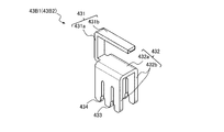
- the power supply connector 43 is formed by inserting two connection terminals 43B1 and 43B2 made of a conductive material into a connector wall 43A made of an insulating material by insert molding. Yes.
- Each of the connection terminals 43B1 and 43B2 has a shape shown in FIG.
- the connection terminals 43B1 and 43B2 have the same shape, and are connected to the power supply connection terminal portion 431 that is connected to the power supply when a power supply side connector (not shown) is fitted, and to the electromagnetic coil 41 when attached to the connector mounting portion 424. And an electromagnetic coil connection terminal portion 432.
- the power connection terminal portion 431 has a base end portion 431a that extends substantially parallel to the axial direction of the field core 44 in a state of being attached to the connector mounting portion 424, and extends radially outward from the one end side of the base end portion 431a.
- a distal end portion 431b that is bent in a substantially L-shape and is surrounded by the connector wall 43A and protrudes into the aforementioned fitting portion 43a.
- the electromagnetic coil connection terminal portion 432 includes a base end portion 432a formed so as to extend from the other end side of the base end portion 431a of the power supply connection terminal portion 431 outward in the radial direction of the field core 44, and an axial direction of the field core 44.
- an electromagnetic coil holding portion 433 formed in a slit shape toward the base end portion 432a side and a distal end portion 432b provided with a diode holding portion 434.
- the electromagnetic coil connection terminal portion 432 is formed in a substantially U shape so that the distal end portions 432b face each other across the base end portion 432a.
- the electromagnetic coil connection terminal portion 432 of the connection terminal 43B is formed in a substantially U shape and has a tip portion 432b facing each other, but the tip portion 432b is not a U shape but a flat plate shape. You may form in.
- the base end portion 431a of the power connection terminal portion 431 and the base end portion 432a of the electromagnetic coil connection terminal portion 432 are arranged in the connector wall 43A. It is. Further, both side edge portions of the tip end portion 432b of the electromagnetic coil connection terminal portion 432 are embedded in the connector wall 43A. Thereby, the axial direction dimension and radial direction dimension of the field core 44 in the power supply connector 43 can be shortened.
- the power supply connector 43 according to the present embodiment includes both side edges of the base end portion 431a of the power connection terminal portion 431, the base end portion 432a of the electromagnetic coil connection terminal portion 432, and the tip end portion 432b of the electromagnetic coil connection terminal portion 432.
- the power supply connector 43 can be miniaturized by disposing it in the connector wall 43A at at least one edge.
- the field core 44 is formed in an annular shape like the rotor 2 as shown in FIGS. That is, the field core 44 is formed by connecting the outer cylindrical portion 441, the inner cylindrical portion 442 concentrically arranged with the outer cylindrical portion 441, and the outer cylindrical portion 441 and the inner cylindrical portion 442 on one end side.
- a through hole 443 a is formed in the connecting portion 443.
- the through hole 443a has a size corresponding to the power supply connector.
- the attachment plate 45 is attached to the outer surface of the connecting portion 443.
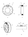
- the field core 44 accommodates the bobbin 42 to which the power supply connector 43 is attached in a space formed by the outer cylindrical portion 441, the inner cylindrical portion 442 and the connecting portion 443. More specifically, as shown in FIGS. 7A to 7D, the field core 44 has a power supply connector in a state where the distal end side of the power supply connector 43 is exposed to the outside through the through hole 443a. The base end side of 43 and the bobbin 42 are accommodated in the space. Thereafter, the resin is filled in the space to seal the electromagnetic coil 41, and the electromagnetic coil 41, bobbin 42, power supply connector 43, and field core 44 are integrated to complete the electromagnetic coil unit 4. Therefore, the space formed by the outer cylindrical portion 441, the inner cylindrical portion 442, and the connecting portion 443 corresponds to the “accommodating portion in which the through hole is formed” of the present invention.
- the electromagnetic coil 41 is wound around the outer peripheral surface of the cylindrical portion 421 of the bobbin 42 in a state where one end side of the electromagnetic coil 41 is pulled out from the notch portion 423 formed in the flange portion 422 of the bobbin 42 to the outside of the flange portion 422.
- the other end of the wound electromagnetic coil 41 is pulled out of the flange 422 from a notch 423 formed in the flange 422 of the bobbin 42.
- one end of the electromagnetic coil 41 is fitted into a first groove 424a formed in the right side portion of the connector mounting portion 424, and the other end of the electromagnetic coil 41 is connected to the left side portion of the connector mounting portion 424. Is fitted into the third groove 424c. At this time, both end portions of the electromagnetic coil 41 are bent in opposite directions.
- one lead wire of the diode is fitted into a second groove portion 424b formed in the right portion of the connector mounting portion 424, and the other lead wire of the diode is inserted into the left portion of the connector mounting portion 424. It fits into the 4 groove part 424d.
- the electromagnetic coil clamping portion 433 and the diode clamping portion 434 formed in a slit shape at the distal end portion 43b of the power supply connector 43 on the electromagnetic coil connection terminal portion 432 side are provided in the respective groove portions 424a to 424d of the connector mounting portion 424.
- the power supply connector 43 is attached to the connector mounting portion 424 so that both ends of the fitted electromagnetic coil 41 and both lead wires of the diode are pressed against each other, and the bobbin 42 and the power supply connector 43 are integrated.
- one connection terminal 43B1 of the power supply connector 43 is electrically connected to one end of the electromagnetic coil 41 and one lead wire of the diode, and the other connection terminal 43B2 of the power supply connector 43 is electromagnetically connected.
- the other end of the coil 41 and the other lead wire of the diode are electrically connected. Further, the power supply connector 43 is attached to the connector mounting portion 424 so that the fitting portion 43a of the power supply connector 43 faces outward in the radial direction of the bobbin 42. Attach to.
- the bobbin 42 to which the power supply connector 43 is attached is accommodated in a space (accommodating portion) formed by the outer cylindrical portion 441, the inner cylindrical portion 442 and the connecting portion 443 of the field core 44.
- the fitting portion 43 a on the distal end side of the power supply connector 43 is exposed to the outside of the field core 44 through a through hole 443 a formed in the connection portion 443 of the field core 44. That is, the power supply connector 43 protrudes from the through-hole 443a substantially parallel to the axial direction of the field core 44, and the field core is in a state where the fitting portion 43a of the power supply connector 43 faces the radially outer side of the field core 44. 44 exposed outside.
- the magnetic characteristics of the electromagnetic clutch 1 are not impaired. Further, the power supply connector 43 does not protrude outward in the radial direction of the field core 44, and the space radially outward of the field core 44 can be used effectively and the installation space of the electromagnetic clutch 1 can be suppressed.
- the mounting plate 45 is attached to the outer surface of the connecting portion 443 of the field core 44, and the assembly of the electromagnetic coil unit 4 is completed.
- the electromagnetic coil unit 4 is accommodated in the rotor 2 while being fixed to the housing 6 of the compressor via the mounting plate 45.
- the power supply connector 43 protrudes outside the field core 44 from the through-hole 443a formed in the connecting portion 443 of the field core 44. Therefore, the field core 44 is provided with a notch. This is not necessary, and the magnetic characteristics of the electromagnetic clutch 1 are not impaired. Further, since the power supply connector 43 has a fitting portion 43a into which the power supply side connector is fitted facing toward the outside in the radial direction of the field core 44, the power supply side connector is powered from the outside in the radial direction of the field core 44. It can be easily fitted into the supply connector 43, and the connection work between the electromagnetic coil 41 and the external power supply is easy. Furthermore, the electromagnetic coil 41 can be electrically connected to the connection terminals 43B1 and 43B2 simply by fitting the power supply connector 43 into the connector mounting portion 424. The mounting work of the cap member to the connection terminal portion is not necessary.
- connection terminals 43B1 and 43B2 of the power supply connector 43 are formed in a substantially U shape, and the base end 431a of the power connection terminal 431 and the base end 432a of the electromagnetic coil connection terminal 432 are connected to the connector wall 43A.
- the axial dimension and the radial dimension of the field core 44 in the power supply connector 43 can be reduced.
- the exposed dimension from the field core 44 of the power supply connector 43 can be shortened, and the situation where the power supply connector 43 interferes with the compressor and the electromagnetic clutch 1 cannot be mounted can be prevented. For this reason, the compressor which can be mounted
- the electromagnetic clutch 1 can be easily manufactured compared to the conventional case. Thus, the number of manufacturing steps and manufacturing costs can be greatly reduced. Furthermore, since the size of the power supply connector 43 protruding outside from the through hole 443a of the field core 44 is short, the space outside the axial direction of the field core 44 can be used effectively and the installation space of the electromagnetic clutch 1 can be suppressed. .
Landscapes
- Engineering & Computer Science (AREA)
- General Engineering & Computer Science (AREA)
- Mechanical Engineering (AREA)
- Physics & Mathematics (AREA)
- Electromagnetism (AREA)
- Electromagnets (AREA)
Abstract
Priority Applications (4)
| Application Number | Priority Date | Filing Date | Title |
|---|---|---|---|
| US14/780,923 US20160053829A1 (en) | 2013-03-29 | 2014-03-26 | Electromagnetic Clutch |
| CN201480018732.1A CN105121889A (zh) | 2013-03-29 | 2014-03-26 | 电磁离合器 |
| DE112014001725.6T DE112014001725T5 (de) | 2013-03-29 | 2014-03-26 | Elektromagnetische Kupplung |
| JP2015508578A JP6353439B2 (ja) | 2013-03-29 | 2014-03-26 | 電磁クラッチ |
Applications Claiming Priority (2)
| Application Number | Priority Date | Filing Date | Title |
|---|---|---|---|
| JP2013074753 | 2013-03-29 | ||
| JP2013-074753 | 2013-03-29 |
Publications (1)
| Publication Number | Publication Date |
|---|---|
| WO2014157301A1 true WO2014157301A1 (fr) | 2014-10-02 |
Family
ID=51624264
Family Applications (1)
| Application Number | Title | Priority Date | Filing Date |
|---|---|---|---|
| PCT/JP2014/058450 Ceased WO2014157301A1 (fr) | 2013-03-29 | 2014-03-26 | Embrayage électromagnétique |
Country Status (5)
| Country | Link |
|---|---|
| US (1) | US20160053829A1 (fr) |
| JP (1) | JP6353439B2 (fr) |
| CN (1) | CN105121889A (fr) |
| DE (1) | DE112014001725T5 (fr) |
| WO (1) | WO2014157301A1 (fr) |
Cited By (2)
| Publication number | Priority date | Publication date | Assignee | Title |
|---|---|---|---|---|
| WO2016170428A1 (fr) * | 2015-04-24 | 2016-10-27 | Magna Powertrain, Inc. | Embrayage sélectionnable à commande électronique doté d'un module à montant actif et procédés d'assemblage et de réglage d'un espace magnétique associés |
| JP2021071115A (ja) * | 2019-10-29 | 2021-05-06 | ファナック株式会社 | 電動機の電磁ブレーキ |
Families Citing this family (4)
| Publication number | Priority date | Publication date | Assignee | Title |
|---|---|---|---|---|
| JP6740712B2 (ja) * | 2016-05-25 | 2020-08-19 | アイシン精機株式会社 | 駆動力断接装置 |
| US12104659B2 (en) | 2019-10-25 | 2024-10-01 | The Hilliard Corporation | Flexible armature plate for an electro-magnetic overrunning clutch |
| US10989258B1 (en) | 2019-10-25 | 2021-04-27 | The Hilliard Corporation | Flexible armature plate for an electro-magnetic overrunning clutch |
| JP7734502B2 (ja) * | 2021-03-31 | 2025-09-05 | 小倉クラッチ株式会社 | 電磁連結装置 |
Citations (8)
| Publication number | Priority date | Publication date | Assignee | Title |
|---|---|---|---|---|
| JPH0259327U (fr) * | 1988-10-25 | 1990-04-27 | ||
| JPH03108937U (fr) * | 1990-02-26 | 1991-11-08 | ||
| JPH10231860A (ja) * | 1996-12-16 | 1998-09-02 | Ogura Clutch Co Ltd | 電磁連結装置 |
| JP2000179591A (ja) * | 1998-12-18 | 2000-06-27 | Ogura Clutch Co Ltd | 電磁クラッチの励磁装置 |
| JP2000266083A (ja) * | 1999-03-18 | 2000-09-26 | Sanden Corp | 導線接続用端子部材 |
| JP2005048878A (ja) * | 2003-07-29 | 2005-02-24 | Hitachi Ltd | 電磁クラッチ用コイル |
| JP2009273354A (ja) * | 2008-05-06 | 2009-11-19 | Halla Climate Control Corp | 圧縮機用電磁クラッチのフィールドコイルアセンブリ及びその製造方法 |
| JP2013174272A (ja) * | 2012-02-23 | 2013-09-05 | Sanden Corp | 電磁クラッチ |
Family Cites Families (10)
| Publication number | Priority date | Publication date | Assignee | Title |
|---|---|---|---|---|
| US5138293A (en) * | 1990-09-17 | 1992-08-11 | Ogura Clutch, Co., Ltd. | Terminal connection structure of electromagnetic coupling device |
| US5508671A (en) * | 1994-08-09 | 1996-04-16 | Qgura Clutch Co., Ltd. | Electromagnetic coupling device |
| JP3069044B2 (ja) * | 1996-05-07 | 2000-07-24 | サンデン株式会社 | 電磁連結装置 |
| JP2000179581A (ja) * | 1998-12-18 | 2000-06-27 | Ogura Clutch Co Ltd | 電磁クラッチの励磁装置 |
| JP2003074596A (ja) * | 2001-09-03 | 2003-03-12 | Sanden Corp | 電磁クラッチ用ヨーク |
| JP4268615B2 (ja) * | 2003-01-29 | 2009-05-27 | ハラ クライメイト コントロール コーポレイション | フィールドコイルアセンブリの構造 |
| JP2006349119A (ja) * | 2005-06-20 | 2006-12-28 | Kyocera Mita Corp | 電磁クラッチ |
| KR101197274B1 (ko) * | 2008-06-16 | 2012-11-05 | 우리산업 주식회사 | 전자클러치의 필드코일조립체 |
| JP5600034B2 (ja) * | 2009-08-28 | 2014-10-01 | 小倉クラッチ株式会社 | 電磁連結装置 |
| EP2339196B1 (fr) * | 2009-12-22 | 2015-11-04 | Halla Visteon Climate Control Corporation | Ensemble de bobine de champ d'embrayage électromagnétique pour appareil de transmission de puissance et son procédé de fabrication |
-
2014
- 2014-03-26 WO PCT/JP2014/058450 patent/WO2014157301A1/fr not_active Ceased
- 2014-03-26 JP JP2015508578A patent/JP6353439B2/ja not_active Expired - Fee Related
- 2014-03-26 DE DE112014001725.6T patent/DE112014001725T5/de not_active Withdrawn
- 2014-03-26 US US14/780,923 patent/US20160053829A1/en not_active Abandoned
- 2014-03-26 CN CN201480018732.1A patent/CN105121889A/zh active Pending
Patent Citations (8)
| Publication number | Priority date | Publication date | Assignee | Title |
|---|---|---|---|---|
| JPH0259327U (fr) * | 1988-10-25 | 1990-04-27 | ||
| JPH03108937U (fr) * | 1990-02-26 | 1991-11-08 | ||
| JPH10231860A (ja) * | 1996-12-16 | 1998-09-02 | Ogura Clutch Co Ltd | 電磁連結装置 |
| JP2000179591A (ja) * | 1998-12-18 | 2000-06-27 | Ogura Clutch Co Ltd | 電磁クラッチの励磁装置 |
| JP2000266083A (ja) * | 1999-03-18 | 2000-09-26 | Sanden Corp | 導線接続用端子部材 |
| JP2005048878A (ja) * | 2003-07-29 | 2005-02-24 | Hitachi Ltd | 電磁クラッチ用コイル |
| JP2009273354A (ja) * | 2008-05-06 | 2009-11-19 | Halla Climate Control Corp | 圧縮機用電磁クラッチのフィールドコイルアセンブリ及びその製造方法 |
| JP2013174272A (ja) * | 2012-02-23 | 2013-09-05 | Sanden Corp | 電磁クラッチ |
Cited By (3)
| Publication number | Priority date | Publication date | Assignee | Title |
|---|---|---|---|---|
| WO2016170428A1 (fr) * | 2015-04-24 | 2016-10-27 | Magna Powertrain, Inc. | Embrayage sélectionnable à commande électronique doté d'un module à montant actif et procédés d'assemblage et de réglage d'un espace magnétique associés |
| JP2021071115A (ja) * | 2019-10-29 | 2021-05-06 | ファナック株式会社 | 電動機の電磁ブレーキ |
| JP7473320B2 (ja) | 2019-10-29 | 2024-04-23 | ファナック株式会社 | 電動機の電磁ブレーキ |
Also Published As
| Publication number | Publication date |
|---|---|
| CN105121889A (zh) | 2015-12-02 |
| US20160053829A1 (en) | 2016-02-25 |
| JPWO2014157301A1 (ja) | 2017-02-16 |
| DE112014001725T5 (de) | 2015-12-17 |
| JP6353439B2 (ja) | 2018-07-04 |
Similar Documents
| Publication | Publication Date | Title |
|---|---|---|
| JP6353439B2 (ja) | 電磁クラッチ | |
| JP5600034B2 (ja) | 電磁連結装置 | |
| WO2013125452A1 (fr) | Embrayage électromagnétique | |
| US7772946B2 (en) | Electric power connection part of electromagnetic clutch field coil assembly | |
| JP2015516134A (ja) | 自動車のユニットを駆動するための直流モータ | |
| JP2011004569A (ja) | モータ | |
| JP2014209022A (ja) | 電磁クラッチ及び電磁クラッチの製造方法 | |
| US10749406B2 (en) | Blower device | |
| JPH1089385A (ja) | 電磁クラッチ | |
| JP2019193575A (ja) | 回転装置 | |
| US10644562B2 (en) | Blower device | |
| EP3456978B1 (fr) | Dispositif de soufflage | |
| US7902949B2 (en) | Electric power connection part of magnetic clutch field coil assembly | |
| JP2016082876A (ja) | ブラシレスモータ | |
| US20190078588A1 (en) | Blower device | |
| JP2001041263A (ja) | 電磁クラッチおよびその組付方法 | |
| WO2015052778A1 (fr) | Embrayage électromagnétique | |
| KR101899779B1 (ko) | 압축기용 전자클러치 | |
| KR101162054B1 (ko) | 압축기용 전자클러치의 서지방지소자 고정구조 | |
| WO2018043197A1 (fr) | Moteur et dispositif rotatif équipé d'un moteur | |
| JP2017211045A (ja) | 電磁クラッチ | |
| JP2020085173A (ja) | 電磁クラッチ | |
| JP4749029B2 (ja) | 電磁クラッチ | |
| JP2019040977A (ja) | 電磁コイルユニット、及び、電磁コイルユニットを備えた電磁クラッチ | |
| WO2021200479A1 (fr) | Moteur électrique |
Legal Events
| Date | Code | Title | Description |
|---|---|---|---|
| 121 | Ep: the epo has been informed by wipo that ep was designated in this application |
Ref document number: 14772616 Country of ref document: EP Kind code of ref document: A1 |
|
| ENP | Entry into the national phase |
Ref document number: 2015508578 Country of ref document: JP Kind code of ref document: A |
|
| WWE | Wipo information: entry into national phase |
Ref document number: 14780923 Country of ref document: US |
|
| WWE | Wipo information: entry into national phase |
Ref document number: 112014001725 Country of ref document: DE Ref document number: 1120140017256 Country of ref document: DE |
|
| 122 | Ep: pct application non-entry in european phase |
Ref document number: 14772616 Country of ref document: EP Kind code of ref document: A1 |