WO2014157478A1 - Dispositif de guidage d'instrument médical - Google Patents
Dispositif de guidage d'instrument médical Download PDFInfo
- Publication number
- WO2014157478A1 WO2014157478A1 PCT/JP2014/058779 JP2014058779W WO2014157478A1 WO 2014157478 A1 WO2014157478 A1 WO 2014157478A1 JP 2014058779 W JP2014058779 W JP 2014058779W WO 2014157478 A1 WO2014157478 A1 WO 2014157478A1
- Authority
- WO
- WIPO (PCT)
- Prior art keywords
- endoscope
- treatment instrument
- treatment
- insertion hole
- insertion portion
- Prior art date
- Legal status (The legal status is an assumption and is not a legal conclusion. Google has not performed a legal analysis and makes no representation as to the accuracy of the status listed.)
- Ceased
Links
Images


Classifications
-
- A—HUMAN NECESSITIES
- A61—MEDICAL OR VETERINARY SCIENCE; HYGIENE
- A61B—DIAGNOSIS; SURGERY; IDENTIFICATION
- A61B1/00—Instruments for performing medical examinations of the interior of cavities or tubes of the body by visual or photographical inspection, e.g. endoscopes; Illuminating arrangements therefor
- A61B1/00147—Holding or positioning arrangements
- A61B1/00154—Holding or positioning arrangements using guiding arrangements for insertion
-
- A—HUMAN NECESSITIES
- A61—MEDICAL OR VETERINARY SCIENCE; HYGIENE
- A61B—DIAGNOSIS; SURGERY; IDENTIFICATION
- A61B1/00—Instruments for performing medical examinations of the interior of cavities or tubes of the body by visual or photographical inspection, e.g. endoscopes; Illuminating arrangements therefor
- A61B1/00064—Constructional details of the endoscope body
- A61B1/00071—Insertion part of the endoscope body
- A61B1/0008—Insertion part of the endoscope body characterised by distal tip features
- A61B1/00087—Tools
-
- A—HUMAN NECESSITIES
- A61—MEDICAL OR VETERINARY SCIENCE; HYGIENE
- A61B—DIAGNOSIS; SURGERY; IDENTIFICATION
- A61B1/00—Instruments for performing medical examinations of the interior of cavities or tubes of the body by visual or photographical inspection, e.g. endoscopes; Illuminating arrangements therefor
- A61B1/00131—Accessories for endoscopes
- A61B1/00133—Drive units for endoscopic tools inserted through or with the endoscope
-
- A—HUMAN NECESSITIES
- A61—MEDICAL OR VETERINARY SCIENCE; HYGIENE
- A61B—DIAGNOSIS; SURGERY; IDENTIFICATION
- A61B1/00—Instruments for performing medical examinations of the interior of cavities or tubes of the body by visual or photographical inspection, e.g. endoscopes; Illuminating arrangements therefor
- A61B1/00131—Accessories for endoscopes
- A61B1/00135—Oversleeves mounted on the endoscope prior to insertion
-
- A—HUMAN NECESSITIES
- A61—MEDICAL OR VETERINARY SCIENCE; HYGIENE
- A61B—DIAGNOSIS; SURGERY; IDENTIFICATION
- A61B1/00—Instruments for performing medical examinations of the interior of cavities or tubes of the body by visual or photographical inspection, e.g. endoscopes; Illuminating arrangements therefor
- A61B1/012—Instruments for performing medical examinations of the interior of cavities or tubes of the body by visual or photographical inspection, e.g. endoscopes; Illuminating arrangements therefor characterised by internal passages or accessories therefor
-
- A—HUMAN NECESSITIES
- A61—MEDICAL OR VETERINARY SCIENCE; HYGIENE
- A61B—DIAGNOSIS; SURGERY; IDENTIFICATION
- A61B1/00—Instruments for performing medical examinations of the interior of cavities or tubes of the body by visual or photographical inspection, e.g. endoscopes; Illuminating arrangements therefor
- A61B1/313—Instruments for performing medical examinations of the interior of cavities or tubes of the body by visual or photographical inspection, e.g. endoscopes; Illuminating arrangements therefor for introducing through surgical openings, e.g. laparoscopes
- A61B1/3132—Instruments for performing medical examinations of the interior of cavities or tubes of the body by visual or photographical inspection, e.g. endoscopes; Illuminating arrangements therefor for introducing through surgical openings, e.g. laparoscopes for laparoscopy
-
- A—HUMAN NECESSITIES
- A61—MEDICAL OR VETERINARY SCIENCE; HYGIENE
- A61B—DIAGNOSIS; SURGERY; IDENTIFICATION
- A61B17/00—Surgical instruments, devices or methods
- A61B17/00234—Surgical instruments, devices or methods for minimally invasive surgery
-
- A—HUMAN NECESSITIES
- A61—MEDICAL OR VETERINARY SCIENCE; HYGIENE
- A61B—DIAGNOSIS; SURGERY; IDENTIFICATION
- A61B17/00—Surgical instruments, devices or methods
- A61B17/34—Trocars; Puncturing needles
- A61B17/3417—Details of tips or shafts, e.g. grooves, expandable, bendable; Multiple coaxial sliding cannulas, e.g. for dilating
- A61B17/3421—Cannulas
- A61B17/3423—Access ports, e.g. toroid shape introducers for instruments or hands
-
- A—HUMAN NECESSITIES
- A61—MEDICAL OR VETERINARY SCIENCE; HYGIENE
- A61B—DIAGNOSIS; SURGERY; IDENTIFICATION
- A61B17/00—Surgical instruments, devices or methods
- A61B17/34—Trocars; Puncturing needles
- A61B17/3462—Trocars; Puncturing needles with means for changing the diameter or the orientation of the entrance port of the cannula, e.g. for use with different-sized instruments, reduction ports, adapter seals
-
- A—HUMAN NECESSITIES
- A61—MEDICAL OR VETERINARY SCIENCE; HYGIENE
- A61B—DIAGNOSIS; SURGERY; IDENTIFICATION
- A61B17/00—Surgical instruments, devices or methods
- A61B17/34—Trocars; Puncturing needles
- A61B17/3403—Needle locating or guiding means
- A61B2017/3405—Needle locating or guiding means using mechanical guide means
- A61B2017/3409—Needle locating or guiding means using mechanical guide means including needle or instrument drives
-
- A—HUMAN NECESSITIES
- A61—MEDICAL OR VETERINARY SCIENCE; HYGIENE
- A61B—DIAGNOSIS; SURGERY; IDENTIFICATION
- A61B17/00—Surgical instruments, devices or methods
- A61B17/34—Trocars; Puncturing needles
- A61B17/3417—Details of tips or shafts, e.g. grooves, expandable, bendable; Multiple coaxial sliding cannulas, e.g. for dilating
- A61B17/3421—Cannulas
- A61B17/3439—Cannulas with means for changing the inner diameter of the cannula, e.g. expandable
- A61B2017/3441—Cannulas with means for changing the inner diameter of the cannula, e.g. expandable with distal sealing means
-
- A—HUMAN NECESSITIES
- A61—MEDICAL OR VETERINARY SCIENCE; HYGIENE
- A61B—DIAGNOSIS; SURGERY; IDENTIFICATION
- A61B17/00—Surgical instruments, devices or methods
- A61B17/34—Trocars; Puncturing needles
- A61B17/3417—Details of tips or shafts, e.g. grooves, expandable, bendable; Multiple coaxial sliding cannulas, e.g. for dilating
- A61B17/3421—Cannulas
- A61B2017/3445—Cannulas used as instrument channel for multiple instruments
- A61B2017/3447—Linked multiple cannulas
-
- A—HUMAN NECESSITIES
- A61—MEDICAL OR VETERINARY SCIENCE; HYGIENE
- A61B—DIAGNOSIS; SURGERY; IDENTIFICATION
- A61B17/00—Surgical instruments, devices or methods
- A61B17/34—Trocars; Puncturing needles
- A61B17/3462—Trocars; Puncturing needles with means for changing the diameter or the orientation of the entrance port of the cannula, e.g. for use with different-sized instruments, reduction ports, adapter seals
- A61B2017/3466—Trocars; Puncturing needles with means for changing the diameter or the orientation of the entrance port of the cannula, e.g. for use with different-sized instruments, reduction ports, adapter seals for simultaneous sealing of multiple instruments
-
- A—HUMAN NECESSITIES
- A61—MEDICAL OR VETERINARY SCIENCE; HYGIENE
- A61B—DIAGNOSIS; SURGERY; IDENTIFICATION
- A61B90/00—Instruments, implements or accessories specially adapted for surgery or diagnosis and not covered by any of the groups A61B1/00 - A61B50/00, e.g. for luxation treatment or for protecting wound edges
- A61B90/08—Accessories or related features not otherwise provided for
- A61B2090/0807—Indication means
- A61B2090/0811—Indication means for the position of a particular part of an instrument with respect to the rest of the instrument, e.g. position of the anvil of a stapling instrument
-
- A—HUMAN NECESSITIES
- A61—MEDICAL OR VETERINARY SCIENCE; HYGIENE
- A61B—DIAGNOSIS; SURGERY; IDENTIFICATION
- A61B90/00—Instruments, implements or accessories specially adapted for surgery or diagnosis and not covered by any of the groups A61B1/00 - A61B50/00, e.g. for luxation treatment or for protecting wound edges
- A61B90/30—Devices for illuminating a surgical field, the devices having an interrelation with other surgical devices or with a surgical procedure
- A61B2090/306—Devices for illuminating a surgical field, the devices having an interrelation with other surgical devices or with a surgical procedure using optical fibres
-
- A—HUMAN NECESSITIES
- A61—MEDICAL OR VETERINARY SCIENCE; HYGIENE
- A61B—DIAGNOSIS; SURGERY; IDENTIFICATION
- A61B90/00—Instruments, implements or accessories specially adapted for surgery or diagnosis and not covered by any of the groups A61B1/00 - A61B50/00, e.g. for luxation treatment or for protecting wound edges
- A61B90/36—Image-producing devices or illumination devices not otherwise provided for
- A61B90/361—Image-producing devices, e.g. surgical cameras
Definitions
- the present invention relates to a medical instrument guide device, and more particularly to a medical instrument guide apparatus that guides an endoscope and a treatment tool into a body cavity so that the endoscope and the treatment tool can move forward and backward, and moves the endoscope forward and backward in conjunction with the forward and backward movement of the treatment tool. .
- a laparoscope is known as an endoscopic instrument that is inserted into the abdominal cavity from the body surface skin. Surgery using this laparoscope (laparoscopic surgery) has been widely used in many surgeries in recent years because the surgical wound is smaller than laparotomy and thoracotomy, and the postoperative period of bed rest can be shortened. .
- Patent Document 1 As a configuration in which a treatment tool and an endoscope are linked, an insertion amount and an inclination of the treatment tool are detected, an optical zoom and an electronic zoom of the endoscope are controlled, and an imaging range of the endoscope A technique for following the movement of the treatment tool is described.
- Patent Documents 2 and 3 a technique is provided in which a marker is provided at the distal end of the treatment instrument, the position of the treatment instrument is detected by detecting the position of the marker, and the imaging range of the endoscope follows the movement of the treatment instrument. Is described.
- Patent Document 4 describes a technique for detecting the position of a treatment tool using a magnetic sensor provided in the treatment tool and causing the imaging range of the endoscope to follow the movement of the treatment tool.
- JP 2007-301378 A Japanese Patent Laid-Open No. 10-118076 JP 2007-222239 A JP-A-8-164148
- the treatment tool may move slightly to the extent that it does not deviate from the scope of the endoscope. Even with such slight movements, the conventional system has a drawback that the imaging range of the endoscope fluctuates following the movement of the treatment instrument, resulting in an image that is difficult for the operator to perform the procedure. .
- the present invention has been made in view of such circumstances, and an object thereof is to provide a medical instrument guide device capable of obtaining an image desired by an operator with a simple configuration.
- a medical instrument guide device includes a guide member that passes through a body wall and is inserted into a body cavity, and is provided inside the guide member to observe the inside of the body cavity.
- An endoscope insertion hole through which an endoscope can be removably inserted, and a treatment instrument insertion hole provided inside the guide member, through which a treatment instrument for inspecting or treating an affected part in a body cavity can be removably inserted
- An advance / retreat movement transmission mechanism that transmits the advance / retreat movement of the treatment instrument to the endoscope, and has a rotation axis provided inside the guide member and three-dimensionally intersecting with the longitudinal axis of the treatment instrument insertion hole.
- a forward / backward movement transmission mechanism having a rotating member that rotates in accordance with the forward / backward movement of the treatment instrument.
- the endoscope and the treatment tool can be inserted into the body cavity via one guide member, the endoscope and the treatment tool are individually guided into the body cavity. It is not necessary to puncture the patient's body wall with the guide member, and the invasion applied to the patient's body wall can be reduced.
- the endoscope moves forward and backward mechanically in conjunction with the forward and backward movement of the treatment tool via the rotating member of the forward and backward movement transmission mechanism. Therefore, the operation of moving the endoscope forward and backward separately from the operation of the treatment tool so that the treatment portion of the treatment tool is reflected in the field of view of the image photographed by the endoscope becomes unnecessary. Therefore, even one surgeon can perform the surgical operation.
- the forward / backward movement transmission mechanism is configured to mechanically link the treatment tool and the endoscope, it is possible to construct a simple and inexpensive system for tracking the endoscope to the treatment tool.
- the advance / retreat movement transmission mechanism is a rotation member, and includes a treatment instrument side rotation member that rotates in conjunction with the advance / retreat movement of the treatment instrument, and a treatment instrument side rotation member.
- An endoscope side rotation member that rotates in conjunction with the rotation and moves the endoscope forward and backward can be provided.
- the treatment instrument side rotation member rotates, and the endoscope side rotation member rotates in conjunction with the rotation.
- the endoscope side rotating member rotates, the endoscope moves forward and backward in conjunction with the rotation. Therefore, the endoscope moves back and forth in conjunction with the advance / retreat movement of the treatment instrument.
- the endoscope side rotation member is connected in direct contact with the treatment instrument side rotation member, and rotates in conjunction with the rotation of the treatment instrument side rotation member. be able to.
- the treatment instrument-side rotation member and the endoscope-side rotation member can be linked via an arbitrary interlocking mechanism.
- the treatment instrument-side rotation member and the endoscope are linked. It is possible to reduce the size of the medical instrument guide device by bringing the side rotation member into contact with each other without using a special interlocking mechanism, and reducing the diameter of the portion of the medical instrument guide device that punctures the body wall. Can be achieved.
- the rotation axis of the treatment instrument side rotation member and the rotation axis of the endoscope side rotation member are set to the axis of the treatment instrument insertion hole and the axis of the endoscope insertion hole. It can be set as the aspect arrange
- a plane parallel to these axes can be arranged with the direction orthogonal to the directions of the rotation axis of the treatment instrument-side rotation member and the rotation axis of the endoscope-side rotation member.
- the rotation axis of the treatment instrument side rotation member and the rotation axis of the endoscope side rotation member are three-dimensionally crossed (becomes a positional relationship of torsion). can do.
- the directions of the rotation axis of the treatment instrument side rotation member and the rotation axis of the endoscope side rotation member are not necessarily parallel but can be three-dimensionally intersecting.
- the rotation shaft of the rotating member is arranged in parallel to the outer surface of the treatment instrument and the plane that is in contact with the outer surface of the endoscope from the same direction. can do.
- the endoscope and the treatment tool can be interlocked even with one rotating member, the number of parts can be reduced, and the medical instrument guide device can be reduced in size and diameter. it can.
- the axis of the treatment instrument insertion hole and the axis of the endoscope insertion hole are arranged non-parallel, and the rotation axis of the rotating member is the axis of the treatment instrument insertion hole.
- it can be set as the aspect arrange
- the rotating member can be arranged with the direction perpendicular to the plane parallel to the axis of the treatment instrument insertion hole and the axis of the endoscope insertion hole as the direction of the rotation axis.
- the treatment instrument has an operation part, an insertion part, and a treatment part
- the insertion part has a large-diameter part having a first outer diameter and a first outer part.
- a rotating member that contacts the large-diameter portion and rotates as the treatment instrument advances and retreats, and contacts the small-diameter portion. Without this, it is possible to adopt a mode in which the treatment tool does not rotate as the treatment tool advances and retreats.
- the rotating member is not interlocked with the advance / retreat movement of the treatment instrument. Therefore, when the surgeon is performing treatment using the treatment tool, the endoscope does not move forward / backward for a slight advance / retreat movement that does not deviate from the scope of the endoscope. Can be. Therefore, it is possible to prevent a problem that an image that is difficult for a surgeon to perform an operation, in which the imaging range of the endoscope changes following the slight movement of the treatment tool.
- the treatment tool insertion hole has a play generating member, and the rotating member transmits the advance / retreat movement of the treatment tool to the endoscope via the play generating member; can do.
- the endoscope insertion hole has a play generating member, and the rotating member transmits the advance / retreat movement of the treatment instrument to the endoscope via the play generating member. It can be.
- an image desired by an operator can be obtained with a simple configuration.
- FIG. 9 is a cross-sectional view taken along line 9-9 in FIG. It is the enlarged view to which the valve member periphery part in FIG. 8 was expanded. It is a disassembled perspective view which shows schematic structure of a valve member.
- FIG. 13 is a sectional view taken along arrow 13-13 in FIG. It is the perspective view which showed the cross section in FIG. 13 from diagonally.
- FIG. 13 is a diagram illustrating a state in which an endoscope insertion portion and a treatment instrument insertion portion are inserted through each of the endoscope insertion hole and the treatment instrument insertion hole in the enlarged view of FIG. 12.
- FIG. 9 is a side cross-sectional view illustrating a state in which an endoscope insertion portion and a treatment instrument insertion portion are inserted into each of the endoscope insertion hole and the treatment instrument insertion hole in the side cross-sectional view of FIG. 8.
- FIG. 16 is a partially enlarged view of FIG. 15, showing a case where a protrusion or a biasing member is provided on the inner peripheral surface of the endoscope insertion hole. It is side surface sectional drawing of the mantle tube which showed the modification of the interlocking mechanism of 1st Embodiment. It is side surface sectional drawing of the mantle tube which showed the modification of the interlocking mechanism of 1st Embodiment. It is side surface sectional drawing of the mantle tube which showed the modification of the interlocking mechanism of 1st Embodiment. It is side surface sectional drawing of the mantle tube which showed the modification of the interlocking mechanism of 1st Embodiment.
- FIG. 26 is a rear perspective view of the mantle tube of FIG. 25.
- FIG. 26 is a front perspective view of the mantle tube of FIG. 25. It is the schematic which showed the mantle tube of FIG.
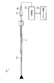
- FIG. 1 is a schematic configuration diagram of an endoscopic surgical apparatus.
- An endoscopic surgical apparatus 1 includes an endoscope 10 that is inserted into a body cavity of a patient and observes the inside of the body cavity, a treatment tool 50 that is inserted into the body cavity of the patient and performs a required treatment,
- the outer tube 100 (medical instrument guide device) for guiding the endoscope 10 and the treatment instrument 50 into the body cavity of the patient is configured.
- FIG. 2 is a schematic configuration diagram of the endoscope system.
- the endoscope 10 is an electronic endoscope and constitutes an endoscope system together with the processor device 30 and the monitor 32.
- the endoscope 10 used in the endoscopic surgical apparatus 1 according to the present embodiment is a rigid endoscope such as a laparoscope.
- the endoscope 10 includes a hollow round bar-shaped insertion portion 12 (endoscope insertion portion 12).
- the endoscope insertion part 12 has an observation window 14 at the tip (see FIG. 3).
- the endoscope 10 observes the inside of the body cavity from the observation window 14 at the distal end of the insertion portion 12.
- FIG. 3 is a cross-sectional view showing a schematic configuration inside the distal end portion of the endoscope insertion portion.
- the endoscope insertion unit 12 incorporates an imaging device 20 at the tip. An image observed from the observation window 14 is captured by the imaging device 20.
- the imaging device 20 includes a lens group 22, a prism 24, an imaging element 26 (CCD (ChargeCharCoupled Device), CMOS (Complementary Metal Oxide Semiconductor), etc.) and the like.
- CCD ChargeCharCoupled Device
- CMOS Complementary Metal Oxide Semiconductor
- the subject light incident from the observation window 14 passes through the lens group 22, is reflected at a substantially right angle by the prism 24, and enters the light receiving surface of the image sensor 26. Thereby, an image observed from the observation window 14 is captured by the image sensor 26.
- the various signal lines 28 connected to the imaging device 20 are arranged inside the endoscope insertion portion 12 and are drawn out from the rear end portion of the endoscope insertion portion 12.
- the processor device 30 in FIG. 2 is a device that performs overall control of the entire endoscope system.
- the processor device 30 is connected to the endoscope 10 via an endoscope cable 16 extending from the rear end of the endoscope insertion portion 12. Further, it is connected to the monitor 32 via the monitor cable 34.
- Power and control signals for operating the imaging device 20 are transmitted from the processor device 30 to the endoscope 10.
- an image signal output from the imaging device 20 is transmitted from the endoscope 10 to the processor device 30.
- the processor device 30 processes the image signal obtained from the endoscope 10 and outputs it to the monitor 32. Thereby, an image in the body cavity observed from the observation window 14 of the endoscope 10 is displayed on the monitor 32.
- the endoscope 10 of this example is not provided with illumination means.
- the illumination is performed by another means, for example, a needle light.
- the diameter of the endoscope insertion portion can be reduced.
- the diameter of the outer tube 100 can also be reduced, and the invasion applied to the patient's body wall can be reduced.
- the endoscope 10 may be provided with illumination means.
- the endoscope 10 of this example is configured to include the imaging device 20 at the distal end portion of the endoscope insertion portion 12, but includes the imaging device 20 at the rear end portion of the endoscope insertion portion 12. It can also be configured. In other words, an image observed from the observation window 14 can be transmitted by a relay lens or the like and imaged by an imaging device disposed at the rear end portion of the endoscope insertion portion 12.
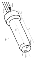
- FIG. 4 is a schematic configuration diagram illustrating an example of a needle light.
- the needle light 40 is inserted into a patient's body cavity and irradiates the body cavity with illumination light.
- the needle light 40 has a round bar-shaped insertion portion 42.
- An illumination window (not shown) is provided at the distal end of the insertion portion 42, and illumination light is irradiated from the illumination window in the axial direction.
- An optical fiber bundle that transmits illumination light emitted from the illumination window is accommodated in the insertion portion 42.
- a connecting portion 44 is provided at the rear end of the needle light 40.
- a flexible needle light cable 46 is connected to the connecting portion 44, and a light source device 48 is connected via the needle light cable 46. Illumination light emitted from the illumination window is supplied from the light source device 48.
- the light source device 48 is connected to the processor device 30 via a cable, and the amount of light is controlled.
- the needle light 40 is inserted into a body cavity via a needle light outer tube 41.
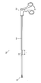
- FIG. 5 is a schematic configuration diagram illustrating an example of a treatment tool.
- the treatment instrument 50 includes a straight rod-like insertion part 52 (treatment instrument insertion part 52) to be inserted into a body cavity, a treatment part 54 disposed at the distal end of the treatment instrument insertion part 52, and a treatment instrument insertion part 52 A handle portion (operation portion) 56 disposed at the end is provided.
- the treatment portion 54 shown in FIG. 5 has a scissor structure, and the treatment portion 54 is opened and closed by opening and closing the handle portion 56.
- the treatment instrument insertion portion 52 is formed with a reduced diameter portion (thin diameter portion) 58 having an outer diameter reduced from the front and rear thereof in a partial range in the direction along the central axis. The operation of the reduced diameter portion 58 will be described later.
- the treatment instrument 50 is not limited to this, and forceps, a laser probe, a suture instrument, an electric knife, a needle holder, an ultrasonic aspirator, and the like can be used as the treatment instrument.
- the mantle tube 100 shown in FIG. 1 is punctured into the body cavity wall of a patient, and the endoscope 10 and the treatment tool 50 are inserted into the inside of the outer tube 100 to guide the endoscope 10 and the treatment tool 50 into the body cavity of the patient. .
- FIG. 6 is a rear perspective view showing the mantle tube 100 from the rear
- FIG. 7 is a front perspective view showing the mantle tube 100 from the front.
- the mantle tube 100 is formed in a cylindrical shape with a longitudinal axis 100 x serving as an insertion direction (front-rear direction) into a body cavity as a central axis, and a body cavity wall (body wall) and body cavity It is formed of a front insertion portion 110 that can be inserted into the inside, and a rear head portion 112 that is larger in diameter than the insertion portion 110 and disposed outside the body.
- a circular rear end surface 102 orthogonal to the longitudinal axis 100x is formed at the rear end of the head portion 112, and the insertion portion 12 (endoscope insertion portion 12) of the endoscope 10 is sheathed on the rear end surface 102.
- An endoscope insertion port 120a for insertion into the tube 100 and a treatment instrument insertion port 122a for inserting the insertion part 52 (treatment instrument insertion part 52) of the treatment instrument 50 into the outer tube 100 are provided.
- a circular front end surface 104 orthogonal to the longitudinal axis 100x is formed at the front end of the insertion portion 110, and the endoscope insertion portion 12 inserted from the endoscope insertion port 120a is sheathed on the front end surface 104.
- An endoscope feeding port 120b that feeds out of the tube 100 and a treatment tool feeding port 122b that feeds the treatment tool insertion portion 52 inserted from the treatment tool insertion port 122a out of the outer tube 100 are provided.
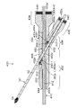
- FIG. 8 is a side sectional view of the mantle tube 100.
- the outer tube 100 includes an outer tube body 130 as a guide member that forms substantially the entire outer tube 100, and a valve provided on the rear end side of the outer tube 100 (the rear end of the head portion 112).
- a member 132 and an interlocking mechanism 134 provided inside the outer tube 100 (inside the insertion portion 110) are provided.
- the outer tube main body 130 is a main member of the outer tube 100 for forming and holding a required space inside the outer tube 100, for example, a metal such as stainless steel or aluminum, or a material having rigidity such as hard plastic Thus, a non-space portion inside the outer tube 100 is formed.
- the outer tube main body 130 is not integrally formed, and may be formed by joining a plurality of members.
- a cylindrical recess 140 is formed at the rear end of the outer tube body 130, and a cylindrical valve member 132 is fitted and fixed to the recess 140. Accordingly, the valve member 132 is disposed on the rear end side of the outer tube 100.
- the rear end surface 102 of the outer tube 100 is formed by the end surface of the outer tube body 130 surrounding the valve member 132 and the periphery thereof.
- the endoscope is inserted with the endoscope insertion shaft 120x parallel to the longitudinal axis 100x as the central axis.
- a hole 120 and a treatment instrument insertion hole 122 having a treatment instrument insertion axis 122x parallel to the longitudinal axis 100x and the endoscope insertion axis 120x as a central axis are formed.
- the endoscope insertion hole 120 forms a circular cross-sectional lumen (pipe) having a diameter slightly larger than the outer diameter (diameter) of the endoscope insertion portion 12 guided by the outer tube 100 into the body cavity. Yes.
- the front end side extends to the front end surface 104 of the outer tube 100 and forms the above-described endoscope delivery port 120 b on the front end surface 104.
- the rear end side of the endoscope insertion hole 120 is formed up to the rear end surface of the outer tube main body 130 (the bottom surface of the recess 140).
- the endoscope insertion hole 120 communicates with the outer tube body 130 and extends to the valve member 132, and forms the above-described endoscope insertion port 120 a on the rear end surface 102 of the outer tube 100.
- an endoscope insertion hole 120 through which the endoscope 10 (endoscope insertion portion 12) can be inserted into the mantle tube 100 so as to advance and retreat is provided in the mantle tube.
- the endoscope insertion portion 12 is inserted from the endoscope insertion port 120 a on the rear end surface 102 of the outer tube 100, the endoscope insertion is performed such that the central axis of the endoscope insertion portion 12 is the central axis of the endoscope insertion hole 120. While passing through a position that substantially overlaps the shaft 120 x, it is guided to the endoscope insertion hole 120 and is fed out from the endoscope feeding port 120 b on the front end surface 104 of the outer tube 100.
- the treatment instrument insertion hole 122 forms a circular cross-sectional lumen having a diameter slightly larger than the outer diameter (diameter) of the treatment instrument insertion portion 52 guided into the body cavity by the outer tube 100.
- the front end side extends to the front end surface 104 of the outer tube 100 and forms the above-described treatment instrument delivery port 122 b on the front end surface 104.
- the rear end side of the treatment instrument insertion hole 122 is formed up to the rear end surface of the mantle tube main body 130 (the bottom surface of the recess 140).
- the treatment instrument insertion hole 122 communicates with the outer tube body 130 and extends to the valve member 132, and forms the above-described treatment instrument insertion port 122 a on the rear end surface 102 of the outer tube 100.
- a treatment instrument insertion hole 122 through which the treatment instrument 50 (treatment instrument insertion portion 52) can be inserted into the outer tube 100 so as to advance and retreat is provided.
- the central axis of the treatment instrument insertion section 52 passes through a position where the treatment instrument insertion shaft 122 x of the treatment instrument insertion hole 122 substantially overlaps. While being guided by the treatment instrument insertion hole, the treatment instrument is fed out from the treatment instrument delivery port 122b of the front end face 104 of the outer tube 100.
- valve member 132 fixed to the recess 140 at the rear end of the outer tube body 130 contains, for example, insufflation gas (carbon dioxide gas or the like) for inflating the body cavity sent into the body cavity by the insufflation apparatus. It is provided to prevent leakage outside the body through the endoscope insertion hole 120 and the treatment instrument insertion hole 122.
- insufflation gas carbon dioxide gas or the like
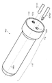
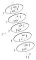
- FIG. 10 is an enlarged view of the periphery of the valve member 132 in FIG. 8, and FIG. 11 is an exploded perspective view showing a schematic configuration of the valve member 132. As shown in FIG.
- the valve member 132 includes, in order from the rear end side to the front end side along the longitudinal axis 100x, the rear holding member 150, the first valve body 152, the intermediate member 154, 2 valve bodies 156 and a front holding member 158 are provided.
- These members 150 to 158 are circular plate-shaped members (disk-shaped members) having the same outer diameter, and are integrated by being arranged on the same axis to constitute the valve member 132.
- the shaft is attached to the outer tube body 130 so that the shaft overlaps the longitudinal axis 100x.
- the rear holding member 150, the intermediate member 154, and the front holding member 158 are made of a metal having a rigidity such as a metal such as stainless steel or aluminum, or a hard plastic, and are sandwiched between the first valve bodies 152. And the second valve body 156.
- the rear holding member 150, the intermediate member 154, and the front holding member 158 have holes 120c to 120e, 122c to 122e (see FIG. 11) that form the endoscope insertion hole 120 and the treatment instrument insertion hole 122 described above. ) Are formed, the central axes of the holes 120c to 120e are arranged at a position overlapping the endoscope insertion shaft 120x, and the central axes of the holes 122c to 122e are arranged at a position overlapping the treatment instrument insertion shaft 122x.
- the rear surface of the rear holding member 150 forms the rear end surface 102 of the outer tube 100, and the openings of the rear ends of the holes 120c and 122c of the rear side holding member 150 are the endoscope insertion port 120a and the treatment instrument insertion port. 122a.
- Both the first valve body 152 and the second valve body 156 are formed so as to be elastically deformable by an elastic material such as natural rubber, synthetic rubber, silicone rubber or the like.
- the first valve body 152 is formed with an opening type airtight valve portion 152a for an endoscope and a slit type airtight valve portion 152b for a treatment instrument (see FIG. 11).
- the endoscope opening-type airtight valve portion 152a is a circular opening whose inner diameter is slightly smaller than the outer diameter of the endoscope insertion portion 12, and the center of the opening is disposed on the endoscope insertion shaft 120x. . Therefore, when the endoscope insertion portion 12 is fitted into the endoscope opening-type airtight valve portion 152 a, the periphery of the opening is brought into close contact with the outer peripheral surface of the endoscope insertion portion 12. Thereby, when the endoscope insertion portion 12 is inserted into the endoscope insertion hole 120, a gap formed between the endoscope insertion portion 12 and the endoscope insertion hole 120 is sealed.
- the treatment instrument slit type airtight valve portion 152b is formed as a single linear slit having a predetermined length, and the center of the slit is disposed on the treatment instrument insertion shaft 122x.
- the treatment instrument slit type airtight valve portion 152 b closes the treatment instrument insertion hole 122 when the treatment instrument insertion portion 52 is removed from the treatment instrument insertion hole 122.
- the second valve body 156 is formed with an opening-type airtight valve portion 156a for a treatment instrument and a slit-type airtight valve portion 156b for an endoscope (see FIG. 11).
- the treatment instrument opening type airtight valve portion 156a is a circular opening whose inner diameter is slightly smaller than the outer diameter of the treatment instrument insertion portion 52, and the center of the opening is disposed on the treatment instrument insertion shaft 122x. . Therefore, when the treatment instrument insertion portion 52 is fitted into the treatment instrument opening-type airtight valve portion 156 a, the periphery of the opening comes into close contact with the outer peripheral surface of the treatment instrument insertion portion 52. Thereby, when the treatment instrument insertion portion 52 is inserted into the treatment instrument insertion hole 122, a gap formed between the treatment instrument insertion section 52 and the treatment instrument insertion hole 122 is sealed.
- the endoscope slit type airtight valve portion 156b is formed as a single linear slit having a predetermined length, and the center of the slit is disposed on the endoscope insertion shaft 120x.
- the endoscope slit-type airtight valve portion 156 b closes the endoscope insertion hole 120 when the endoscope insertion portion 12 is removed from the endoscope insertion hole 120.
- valve member 132 configured as described above, when the endoscope 10 (endoscope insertion portion 12) and the treatment instrument 50 (treatment instrument insertion portion 52) are inserted into the outer tube 100, Airtightness of the outer tube 100 is ensured by the opening-type airtight valve portion 152a for the endoscope and the open-type airtight valve portion 156a for the treatment instrument. Further, when the endoscope insertion portion 12 and the treatment instrument insertion portion 52 are not inserted into the outer tube 100, the endoscope slit type airtight valve portion 156b and the treatment instrument slit type airtight valve portion 152b, Airtightness of the outer tube 100 is ensured.
- the interlocking mechanism 134 provided near the center of the outer tube body 130 in the front-rear direction moves forward and backward (back and forth movement) through the treatment instrument insertion portion 52 inserted through the treatment instrument insertion hole 122.
- a forward / backward movement transmission mechanism that moves the endoscope insertion portion 12 inserted through the endoscope insertion hole 120 forward / backward (forward / backward) via a rotating member that rotates in conjunction with the rotation member. is there.
- this interlocking mechanism 134 the position of the treatment section 54 in the captured image of the endoscope 10 according to the position in the front-rear direction of the treatment section 54 provided at the distal end of the treatment instrument 50.
- the visual field range (position in the front-rear direction of the viewpoint) of the endoscope 10 is changed so as to keep the size constant. Therefore, it is not always necessary to perform an operation of adjusting the visual field range of the endoscope 10 while operating the treatment tool 50, and even if there is no scopist, one surgeon can perform a treatment while looking at a captured image of the endoscope 10. Only the operation of the tool 50 can be performed to perform the treatment.
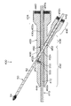
- FIG. 34 is a schematic view showing a usage pattern of the endoscopic surgical apparatus 1 using the mantle tube 100 provided with such an interlocking mechanism 134.
- the endoscope 10 and the treatment tool 50 are inserted into the body cavity 3 through the outer tube 100 punctured in the body cavity wall (body wall) 2 of the patient.
- the endoscope 10 moves back and forth by the interlocking mechanism 134, and when the treatment tool 50 is tilted, the endoscope 10 is tilted together with the outer tube 100. Therefore, the visual field range of the endoscope 10 can be made to follow the treatment section 54, and the image of the treatment portion (treatment section 54) is always displayed on the monitor 32.
- the needle light 40 is used as illumination means.
- the needle light 40 is inserted into the body cavity 3 via the needle light outer tube 41.
- the body cavity 3 is illuminated with illumination light emitted from the tip of the needle light 40.
- the endoscope 10 may include an illumination unit and the needle light 40 is not used.
- the endoscope 10 is also operated by operating the treatment tool 50, so that a single operator can perform treatment. That is, a scopist becomes unnecessary.
- the endoscope 10 and the treatment tool 50 are inserted into the body cavity 3 through the outer tube 100, only one puncture site is required for inserting the endoscope 10 and the treatment tool 50 into the body cavity. Thereby, minimally invasive surgery can be performed.
- the interlock mechanism 134 of the outer tube 100 is provided with a play in which the endoscope insertion portion 12 does not move forward and backward with respect to a slight advance and retreat movement of the treatment instrument insertion portion 52.
- the treatment tool insertion portion 52 treatment portion 54
- the treatment portion 54 is moved forward and backward slightly (position in the front-rear direction) intentionally or unintentionally. Fluctuations) may occur.
- the endoscope insertion unit 12 is interlocked by the interlocking mechanism 134 even with such a slight advance / retreat movement, the captured image (field-of-view range) of the endoscope 10 moves as a whole, making it difficult to perform the treatment.
- the interlock mechanism 134 is provided with play so that unnecessary follow-up of the endoscope insertion portion 12 is not performed.
- FIG. 8 shows the configuration of the interlocking mechanism 134 of the first embodiment
- FIG. 12 shows the interlocking mechanism 134 of FIG.
- FIG. 13 is an enlarged view of the peripheral portion
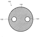
- FIG. 13 is a cross-sectional view taken along arrow 13-13 in FIG.
- FIG. 14 is a perspective view showing the cross section of FIG. 13 from an oblique direction.
- a hollow portion 170 for arranging the interlocking mechanism 134 is formed inside the outer tube body 130.
- the cavity 170 is formed so as to penetrate from the inner peripheral surface 120s of the endoscope insertion hole 120 to the inner peripheral surface 122s of the treatment instrument insertion hole 122, and for example, the endoscope insertion shaft 120x and the treatment instrument insertion.
- the partition wall 130a of the outer tube main body 130 included in a range of a predetermined distance perpendicular to the rectangular plane opposite to the shaft 122x is shaped.
- the endoscope insertion shaft 120x and the treatment instrument insertion shaft 122x are arranged in parallel as described above, and the plane including them is a horizontal reference plane (including the endoscope insertion axis 120x and the treatment instrument).
- the plane parallel to the insertion shaft 122x) the longitudinal axis 100x is the front-rear direction, while the direction perpendicular to the horizontal reference plane is the up-down direction, the horizontal direction is the horizontal reference plane, and the length The direction orthogonal to the axis 100x is the left-right direction.
- the longitudinal axis 100x is also arranged on the same plane as the horizontal reference plane, but the relationship between the horizontal reference plane and the longitudinal axis 100x is not limited to this.
- the interlocking mechanism 134 of the first embodiment includes an endoscope side roller 200 (an endoscope side rotating member) arranged side by side in the left and right directions in the cavity 170.
- a treatment instrument side roller 202 (treatment instrument side rotating member), the endoscope side roller 200 is disposed on the endoscope insertion hole 120 side, and the treatment instrument side roller 202 is disposed on the treatment instrument insertion hole 122 side.
- the endoscope side roller 200 and the treatment instrument side roller 202 are columnar members having the same diameter cylindrical surface (outer peripheral surfaces 200 s, 202 s), and their central axes (rotating axes) are the horizontal reference planes. It arrange
- the end surfaces on both the upper and lower sides of the endoscope side roller 200 and the treatment instrument side roller 202 are along the central axis (rotation axis) of the endoscope side roller 200 and the treatment instrument side roller 202 (outer peripheral surfaces 200 s and 202 s).
- the shaft pins 200a, 200b, 202a, 202b are provided to extend (see FIGS. 13 and 14).
- a pair of engagement holes 172a and 172b and a pair of engagement holes 174a and 174b are formed on the upper and lower wall surfaces in the cavity 170 (see FIG. 13).
- the shaft pins 200a and 200b of the endoscope side roller 200 are inserted into the engagement holes 172a and 172b, respectively, and the shaft pins 202a and 202b of the treatment instrument side roller 202 are respectively inserted into the engagement holes 174a and 174b. It is inserted.
- the endoscope side roller 200 is rotatably supported around the central axis via the shaft pins 200a and 200b in the cavity 170, and the treatment instrument side roller 202 is supported via the shaft pins 202a and 202b. It is supported so as to be rotatable around its central axis.
- the means for rotatably supporting the endoscope side roller 200 and the treatment instrument side roller 202 in the hollow portion 170 may be in any form.
- the endoscope side roller 200 and the treatment instrument side roller 202 may not be configured to rotate with the shaft pin as described above.
- the endoscope side roller 200 and the treatment instrument side roller 202 may be supported so as to be rotatable around a shaft member that passes through the positions of the central axes.
- FIG. 8 shows a cross section of the outer tube body 130 cut along a horizontal reference plane, but the outer tube body 13 is configured by two members separated into two upper and lower regions on the horizontal reference surface. Also good.
- a concave portion for forming the cavity 170 is formed in each member, and the endoscope side roller 200 and the treatment instrument side roller 202 are disposed in one of the concave portions, and then the horizontal reference planes of these two members are arranged. What is necessary is just to contact and fix the surfaces which become.
- only a local region of the outer tube body 130 may be configured as a member that can be separated from the remaining region.
- a passage for inserting and installing the endoscope side roller 200 and the treatment instrument side roller 202 into the cavity 170 from the outside of the outer tube body 130 is provided, and the endoscope side roller 200 and the treatment instrument are provided in the cavity 170.
- the separated member may be fixed so as to close the passage.
- the means for fixing the plurality of separated members can be any means such as bonding with an adhesive or screwing.
- the endoscope side roller 200 and the treatment instrument side roller 202 thus arranged in the cavity 170 are arranged at positions where the outer peripheral surface 200s and the outer peripheral surface 202s are in contact with each other. Thereby, the endoscope side roller 200 and the treatment instrument side roller 202 are connected by frictional force, and the other roller is rotated in conjunction with the rotation of one roller. At this time, the endoscope side roller 200 and the treatment instrument side roller 202 rotate in opposite directions.
- the endoscope side roller 200 protrudes into the endoscope insertion hole 120 from a surface position along the inner peripheral surface 120 s of the endoscope insertion hole 120 in a partial range of the outer peripheral surface 200 s in the circumferential direction.
- the outer peripheral surface 200s of the endoscope-side roller 200 comes into contact with and is connected to the outer peripheral surface 12s of the endoscope insertion portion 12 inserted through the endoscope insertion hole 120 as shown in FIG. ing.
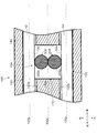
- FIG. 15 shows a state in which the endoscope insertion portion 12 and the treatment instrument insertion portion 52 are inserted through the endoscope insertion hole 120 and the treatment instrument insertion hole 122 in the enlarged view of FIG.
- the endoscope insertion portion 12 moves forward and backward (moves back and forth) in conjunction with the rotation of the endoscope side roller 200, and the endoscope side roller 200 in conjunction with the forward and backward movement of the endoscope insertion portion 12. Rotates.
- the outer peripheral surface 12s of the endoscope insertion portion 12 is not separated from the outer peripheral surface 200s of the endoscope side roller 200. Therefore, depending on design conditions such as the diameter of the endoscope insertion hole 120, the position of the endoscope insertion shaft 120x, or the projection amount of the outer peripheral surface 200s of the endoscope side roller 200 to the endoscope insertion hole 120, It is possible to prevent a gap from being formed between the outer peripheral surface 12 s of the endoscope insertion portion 12 and the inner peripheral surface 120 s of the endoscope insertion hole 120 at a position facing the endoscope side roller 200. Further, as shown in FIG.
- any of the inner peripheral surface 120 s of the endoscope insertion hole 120 such as a position of the inner peripheral surface 120 s of the endoscope insertion hole 120 facing the endoscope side roller 200 or its peripheral part.
- the projection 210 that prevents the endoscope insertion portion 12 from being separated from the endoscope side roller 200 or the endoscope insertion portion 12 is urged in a direction in contact with the endoscope side roller 200.
- An urging member 212 such as a leaf spring may be provided.
- the treatment instrument side roller 202 is arranged such that a partial range in the circumferential direction of the outer peripheral surface 202 s protrudes into the treatment instrument insertion hole 122 from a surface position along the inner peripheral surface 122 s of the treatment instrument insertion hole 122.
- the treatment instrument side is placed on the outer peripheral surface 52 s of the treatment instrument insertion portion 52 inserted into the treatment instrument insertion hole 122 (the outer peripheral surface 52 s of the non-reduced portion excluding the range of the reduced diameter portion 58).
- the outer peripheral surface 202s of the roller 202 comes into contact.
- the treatment instrument side roller 202 rotates in conjunction with the advancement / retraction movement of the treatment instrument insertion section 52, and the treatment instrument insertion section 52 moves forward / backward in conjunction with the rotation of the treatment instrument side roller 202.
- the outer peripheral surface 52s of the treatment instrument insertion portion 52 is not separated from the outer peripheral surface 202s of the treatment instrument side roller 202. Therefore, depending on the design conditions such as the diameter of the treatment instrument insertion hole 122, the position of the treatment instrument insertion shaft 122x, or the protrusion amount of the outer peripheral surface 202s of the treatment instrument side roller 202 to the treatment instrument insertion hole 122, It is possible to prevent a gap from being generated between the outer peripheral surface 52s of 52 and the inner peripheral surface 122s of the treatment instrument insertion hole 122 at a position facing the treatment instrument side roller 202.
- the endoscope side roller 200 and the treatment instrument side roller 202 may be entirely formed integrally of plastic (synthetic resin) or the like, or their outer peripheral surfaces 200s, 202s and contact objects.
- the outer peripheral surfaces 200 s and 202 s are coated with a material having a high friction coefficient, and the outer peripheral surfaces 200 s and 202 s are formed with fine unevenness for preventing slippage. May be.
- a belt-like member made of a material having a large friction coefficient is wound around the outer peripheral portions of the endoscope side roller 200 and the treatment instrument side roller 202 to form outer peripheral surfaces 200 s and 202 s (ring-like members having a large friction coefficient are formed). It may be one that is fitted to the outer peripheral portion), or the endoscope side roller 200 and the treatment instrument side roller 202 may be formed of a material having a large friction coefficient.
- gears are formed on the outer peripheral surfaces of the endoscope side roller 200 and the treatment instrument side roller 202 to form gears, and the endoscope side roller 200 and the treatment instrument side roller 202 are interlocked by engaging them. You may make it make it.
- the treatment instrument side roller 202 (the plate surface of the disk-shaped rotating member) and the outer peripheral surface 52 s of the treatment instrument insertion portion 52 are brought into contact with each other, so that the treatment instrument insertion portion 52 moves forward and backward. Then, the treatment instrument side roller 202 may be rotated.
- the interlocking between the endoscope side roller 200 and the endoscope insertion portion 12 is the same.
- the interlocking mechanism 134 of the first embodiment configured as described above, when the treatment instrument insertion portion 52 inserted into the treatment instrument insertion hole 122 of the outer tube 100 is moved forward and backward, it is interlocked with this.
- the treatment instrument side roller 202 of the interlocking mechanism 134 rotates. For example, when the treatment instrument insertion portion 52 is advanced, the rotation is performed such that the outer peripheral surface 202 s moves forward at the contact position between the outer peripheral surface 202 s of the treatment instrument side roller 202 and the outer peripheral surface 52 s of the treatment instrument insertion portion 52.
- the treatment instrument side roller 202 rotates in the direction (clockwise direction in FIG. 15).
- the endoscope side roller 200 rotates in the opposite direction to the treatment instrument side roller 202.
- the outer peripheral surface 200 s moves backward at the contact position between the outer peripheral surface 200 s of the endoscope side roller 200 and the outer peripheral surface 202 s of the treatment instrument side roller 202.
- the endoscope side roller 200 rotates in the rotation direction (counterclockwise direction in FIG. 15).
- the endoscope insertion portion 12 inserted through the endoscope insertion hole 120 is moved forward and backward in conjunction with the rotation.
- the outer peripheral surface 12s moves forward at the contact position between the outer peripheral surface 12s of the endoscope insertion portion 12 and the outer peripheral surface 200s of the endoscope side roller 200.
- the endoscope insertion part 12 moves forward.
- the movement amount is the same as the movement amount.
- the endoscope insertion portion 12 also moves forward and the treatment instrument insertion portion 52 is retracted, the endoscope insertion portion 12 is also retracted by the same movement amount as the movement amount.
- the treatment instrument insertion portion 52 moves forward and backward in conjunction with this.
- the treatment instrument insertion portion 52 has a reduced diameter portion (small diameter portion) 58 in which the outer diameter is reduced in the partial range in the front-rear direction along the central axis. Is formed. If the range other than the reduced diameter portion 58 of the treatment instrument insertion portion 52 is referred to as a non-reduced diameter portion (thick diameter portion), the reduced diameter portion 58 is larger than the outer diameter (first outer diameter) of the non-reduced diameter portion. The outer diameter (second outer diameter) is small.
- the endoscope insertion portion 12 and the treatment instrument insertion portion 52 are inserted through the endoscope insertion hole 120 and the treatment instrument insertion hole 122, respectively, and is shown in the side sectional view of FIG.
- the reduced diameter portion 58 of the treatment instrument insertion portion 52 is disposed at a position facing the treatment instrument side roller 202 in a state where the treatment instrument insertion portion 52 is fed out from the treatment instrument delivery port 122b of the outer tube 100 by a predetermined amount. It has become so.
- the treatment instrument side roller 202 does not rotate with respect to the forward / backward movement of the treatment instrument insertion portion 52,
- the endoscope insertion portion 12 is not moved forward and backward in conjunction with each other.
- the diameter reducing portion 58 for providing a play in which the endoscope insertion portion 12 does not move back and forth (not interlocked) with respect to the advancement / retraction movement of the treatment instrument insertion portion 52 is provided in the treatment instrument insertion portion 52 as a component of the interlock mechanism 134. Provided.
- the length of the diameter-reduced portion 58 in the front-rear direction of the treatment instrument insertion portion 52 is L, and the center point of the treatment instrument-side roller 202 is opposed to the central axis in the left-right direction (the same position in the front-rear direction). If the treatment instrument insertion portion 52 is moved within the range of L / 2 or less from the position of the state to the front and rear, the outer peripheral surface of the treatment instrument insertion portion 52 52s does not contact the outer peripheral surface 202s of the treatment instrument side roller 202. Therefore, the endoscope insertion unit 12 does not interlock within the range of the movement amount, and becomes a range of play of the interlocking mechanism 134.
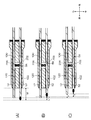
- FIG. 17 and 18 are diagrams illustrating the range of play of the interlocking mechanism 134.
- 17A shows a state in which the central point of the reduced diameter portion 58 of the treatment instrument insertion portion 52 is arranged at the same position in the front-rear direction with respect to the central axis of the treatment instrument side roller 202 as described above.
- the amount of the treatment portion 54 that is fed out from the front end surface 104 (the treatment instrument delivery port 122b) of the outer tube 100 is M.
- the amount of feeding from the front end surface 104 (endoscope outlet 120b) of the outer tube 100 at the tip of the endoscope 10 inserted through the endoscope insertion hole 120 is such that an image in the visual field range desired by the operator can be obtained. It can be adjusted as appropriate (details will be described later).
- the treatment instrument insertion section 52 is advanced to advance the treatment section 54, that is, when the treatment section 54 is advanced further than the position where the movement amount is L / 2, the non-reduced diameter of the treatment instrument insertion section 52 is reached.
- the outer peripheral surface 52s of the part contacts the outer peripheral surface 202s of the treatment instrument side roller 202, and the treatment instrument side roller 202 rotates in the clockwise direction in the figure.
- the endoscope-side roller 200 rotates counterclockwise in the drawing, and the endoscope insertion portion 12 moves forward in conjunction with the advancement of the treatment instrument insertion portion 52 as shown in FIG. 17 (C). To do.
- the movement amount by which the treatment instrument insertion portion 52 is advanced is x
- the distal end of the endoscope insertion portion 12 is also advanced by the movement amount x.
- the central point of the reduced diameter portion 58 of the treatment instrument insertion portion 52 is located at the same position in the front-rear direction with respect to the central axis of the treatment instrument side roller 202, as in the case of FIG. It shows the state of being placed. From this state, when the treatment instrument insertion section 52 is retracted to a position where the movement amount is L / 2 and the treatment section 54 is retracted by the movement amount L / 2, the outer peripheral surface 52s of the treatment instrument insertion section 52 is treated. It does not contact the outer peripheral surface 202 s of the tool side roller 202.
- the treatment instrument side roller 202 of the interlocking mechanism 134 does not rotate, and the position of the distal end of the endoscope insertion portion 12 does not change as shown in FIG. 18B. Further, when the treatment instrument insertion portion 52 is retracted to a position where the amount of movement is L / 2, the front end of the reduced diameter portion 58 of the treatment instrument insertion portion 52, that is, the non-reduced diameter in front of the reduced diameter portion 58. The rear end of the part contacts the outer peripheral surface 202 s of the treatment instrument side roller 202.
- the treatment instrument insertion section 52 is retracted and the treatment section 54 is retracted, that is, when the treatment section 54 is further retracted from the position where the movement amount is L / 2, the non-reduced diameter of the treatment instrument insertion section 52 is reached.
- the outer peripheral surface 52s of the part contacts the outer peripheral surface 202s of the treatment instrument side roller 202, and the treatment instrument side roller 202 rotates counterclockwise in the figure.
- the endoscope side roller 200 rotates in the clockwise direction in the drawing, and the endoscope insertion portion 12 moves backward in conjunction with the retraction of the treatment instrument insertion portion 52 as shown in FIG. 18 (C). .
- the movement amount by which the treatment instrument insertion portion 52 is retracted is x
- the distal end of the endoscope insertion portion 12 is also retracted by the movement amount x.
- play is limited to a state where the treatment portion 54 of the treatment instrument insertion portion 52 is fed out from the outer tube 100 (treatment tool delivery port 122b) with a constant feed amount M, but the operator provides play.
- the insertion amount of the mantle tube 100 into the body cavity (body cavity wall) may be adjusted so as to achieve such a feeding amount M at the insertion position of the treatment portion 54 into the body cavity where the user desires to move.
- a plurality of devices having different distances (positions of the reduced diameter portion 58) from the treatment portion 54 to the reduced diameter portion 58 of the treatment instrument insertion portion 52 are prepared, and play can be performed from among them. May be selected and used so that the feeding amount M of the treatment portion 54 is optimal (the length L of the reduced diameter portion 58 when changing the size of play is selected in the same manner). Can be possible).
- the extension amount of the distal end of the endoscope 10 when the treatment tool 50 has play can be adjusted as appropriate by the operator. For example, when the endoscope insertion part 12 is inserted into the outer tube 100 simultaneously with the treatment tool insertion part 52, or when the treatment tool insertion part 52 is inserted through the outer tube 100 first, the treatment tool 50 plays. In other words, when the endoscope insertion portion 12 is not interlocked with the treatment instrument insertion portion 52, only the endoscope insertion portion 12 is moved forward and backward within the endoscope insertion hole 120. Thus, the distal end of the endoscope insertion portion 12 can be adjusted to a desired feeding amount.
- the endoscope insertion portion 12 is first inserted through the outer tube 100, the endoscope insertion portion 12 is adjusted to a desired feeding amount, and then the treatment instrument insertion portion 52 is inserted into the treatment instrument insertion hole 122.
- the endoscope insertion portion 52 is interlocked with the treatment instrument insertion portion 52 by holding the rear end side of the endoscope insertion portion 12 by hand until the treatment instrument insertion portion 52 has a play state.
- the part 12 may be prevented from moving forward and backward.
- ⁇ Modification of interlocking mechanism of the first embodiment In the interlocking mechanism 134 of the first embodiment, by forming the reduced diameter portion 58 in the treatment instrument insertion portion 52, a range that does not contact the outer peripheral surface 202s of the treatment instrument side roller 202 is provided. Thereby, the non-interlocking part which makes the treatment tool 50 (treatment tool insertion part 52) and the treatment tool side roller 202 non-linkage is provided.
- the configuration of the non-interlocking unit is not limited to this.
- the outer peripheral surface in the range corresponding to the reduced diameter portion 58 is more than the front and rear range (range corresponding to the non-reduced diameter portion).
- the treatment instrument side roller 202 may be prevented from rotating even if the treatment instrument insertion section 52 is moved forward and backward.
- the treatment instrument insertion section 52 is not provided with a non-interlocking section for disengaging the treatment instrument 50 and the treatment instrument side roller 202 like the reduced diameter section 58, but the treatment instrument insertion section 52 is connected to a cylindrical pipe.
- a play may be provided by inserting the treatment instrument insertion portion 52 into the treatment instrument insertion hole 122 together with the pipe-shaped member.
- FIG. 20 is a side cross-sectional view of the mantle tube 100 showing a form in which play is provided by such a pipe-like member as a modified example of the interlocking mechanism 134 of the first embodiment.
- components having the same or similar actions as those of the outer tube 100 having the interlocking mechanism 134 of the first embodiment shown in FIGS. Description is omitted.
- a treatment instrument insertion portion 52 is inserted through the treatment instrument insertion hole 122 and a cylindrical pipe-shaped member 250 is disposed.
- the pipe-shaped member 250 is formed in a long cylindrical shape, and the outer diameter thereof substantially coincides with the inner diameter of the treatment instrument insertion hole 122. Accordingly, the outer peripheral surface 250s of the pipe-shaped member 250 is in contact with the outer peripheral surface 202s of the treatment instrument side roller 202, and when the pipe-shaped member 250 moves in the front-rear direction, the treatment instrument-side roller 202 rotates in conjunction therewith. It is like that.
- the outer diameter of the treatment instrument insertion portion 52 is reduced by the amount of the pipe-shaped member 250 disposed as compared with FIG. 16, but it is not always necessary to reduce the outer diameter of the treatment instrument insertion portion 52.
- the inner diameter of the treatment instrument insertion hole 122 may be increased.
- a through-hole 252 is formed through the pipe-shaped member 250 along its central axis, and the treatment instrument insertion portion 52 is inserted through the through-hole 252.
- the inner diameter of the through hole 252 is slightly larger than the outer diameter of the treatment instrument insertion portion 52, and the treatment instrument insertion portion 52 is inserted so as to be movable forward and backward with respect to the pipe-shaped member 250.
- the treatment instrument insertion portion 52 is not provided with the reduced diameter portion 58 as shown in FIG. 5, and the pipe-like member 250 is provided on the front side and the rear side of the region where the pipe-like member 250 is externally fitted.
- a front engagement portion 254A and a rear engagement portion 254B to be engaged are formed.
- the front engagement portion 254A and the rear engagement portion 254B protrude, for example, in the radial direction with respect to the outer peripheral surface 52s of the treatment instrument insertion portion 52, and extend over the entire circumference or around the circumference. It is formed in a partial range in the direction.
- the front engagement portion 254A and the rear engagement portion 254B are formed at positions where the distance in the front-rear direction is wider than the length in the front-rear direction of the pipe-shaped member 250. Thereby, the pipe-shaped member 250 is movable in the front-rear direction between the engaging portions 254A and 254B.
- the pipe-shaped member 250 is externally fitted to the treatment instrument insertion portion 52 with play.
- a notch in the front-rear direction that is continuous from the front end to the rear end is formed in the pipe-shaped member 250, and the gap between the front engagement portion 254A and the rear engagement portion 254B of the treatment instrument insertion portion 52 is interposed through the cut.
- the pipe-shaped member 250 when the treatment instrument insertion portion 52 is advanced, the pipe-shaped member 250 is in a pipe shape until the rear engagement portion 254 ⁇ / b> B of the treatment instrument insertion portion 52 contacts the rear end of the pipe-shaped member 250.
- the member 250 does not move forward and backward, and the treatment instrument side roller 202 does not rotate. That is, there is a play in which the endoscope insertion portion 12 inserted through the endoscope insertion hole 120 does not interlock with the advance / retreat movement of the treatment instrument insertion portion 52.
- the pipe-shaped member 250 is moved together with the treatment instrument insertion section 52. Advances, and in conjunction with this, the treatment instrument side roller 202 rotates. Therefore, the endoscope insertion portion 12 also moves forward in conjunction with the treatment instrument insertion portion 52.
- the pipe-like member 250 does not move forward and backward until the front engagement portion 254A of the treatment instrument insertion portion 52 contacts the front end of the pipe-like member 250.
- the roller 202 does not rotate. That is, there is a play in which the endoscope insertion portion 12 is not interlocked with the advance / retreat movement of the treatment instrument insertion portion 52.
- the advance / retreat movement of the treatment instrument insertion section 52 (treatment instrument 50) is transmitted to the endoscope insertion section 12 (endoscope 10) via a play generating member such as the pipe-shaped member 250 described above.
- a play generating member such as the pipe-shaped member 250 described above.
- front engagement portion 254A and the rear engagement portion 254B are members that can be attached to and detached from the treatment instrument insertion portion 52 so that the mounting position can be freely changed and the size of play can be adjusted. It may be.
- any configuration can be adopted.
- a partial region in the front-rear direction along the central axis of the treatment instrument insertion portion 52 that is longer in the front-rear direction than the pipe-shaped member 250 is reduced in diameter from the front and rear, and the diameter thereof is reduced.
- the pipe-shaped member 250 may be externally fitted in the region so as to be movable back and forth.
- the inner diameter of the treatment instrument insertion hole 122 is set to the pipe-shaped member 250. It is possible to eliminate the need to expand the diameter in accordance with the outer diameter.
- the play generating member may be arranged not in the treatment instrument insertion hole 122 but in the endoscope insertion hole 120, and the configuration in that case is shown in FIG.
- the same reference numerals are given to components having the same or similar actions as in FIG. 20, and the pipe-like member 250 can be moved forward and backward to the endoscope insertion portion 12 inserted through the endoscope insertion hole 120.
- the endoscope insertion portion 12 is provided with a front engagement portion 254A and a rear engagement portion 254B that are engaged with the pipe-like member 250.
- the treatment instrument side roller 202 is rotated in conjunction with this, the endoscope side roller 200 is rotated, and the pipe-shaped member 250 is advanced.
- the endoscope insertion portion 12 does not move forward and backward until the front end of the pipe-shaped member 250 contacts the front engagement portion 254A of the endoscope insertion portion 12. That is, there is a play in which the endoscope insertion portion 12 is not interlocked with the advance / retreat movement of the treatment instrument insertion portion 52.
- the pipe-like member 250 is retracted in conjunction with this. And the endoscope insertion part 12 does not move forward and backward until the rear end of the pipe-shaped member 250 contacts the rear engagement part 254B of the endoscope insertion part 12. That is, there is a play in which the endoscope insertion portion 12 is not interlocked with the advance / retreat movement of the treatment instrument insertion portion 52.
- Providing the play of the interlocking mechanism 134 using a play generating member such as the pipe-shaped member 250 instead of the reduced diameter part 58 of the treatment instrument insertion part 52 described above is the interlocking of the first embodiment described below.
- the present invention can be similarly applied to the modification of the mechanism 134 and the interlocking mechanism 134 of the second embodiment.
- the endoscope side roller 200 and the treatment instrument side roller 202 are left and right at the same position with respect to the direction along the longitudinal axis 100x of the outer tube 100 (front-rear direction).
- the endoscope side roller 200 and the treatment instrument side roller 202 are not necessarily arranged at the same position in the front-rear direction of the outer tube 100.
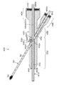
- FIG. 22 is a side cross-sectional view of the outer tube 100 showing the configuration in that case as a modified example of the interlocking mechanism 134 of the first embodiment.
- the endoscope side roller 200 is disposed in front of the treatment instrument side roller 202 in the hollow portion 170 of the outer tube 100, and the center of the endoscope side roller 200 and the treatment instrument side roller 202 are arranged.
- the outer peripheral surface 200 s of the endoscope side roller 200 and the outer peripheral surface 202 s of the treatment instrument side roller 202 are in contact with each other on a line segment connecting the center of the endoscope. As a result, the endoscope side roller 200 and the treatment instrument side roller 202 rotate in conjunction with each other.
- the endoscope-side roller 200 has a part of the outer circumferential surface 200 s in the circumferential direction protruding into the endoscope insertion hole 120, and the outer periphery of the endoscope insertion portion 12 inserted through the endoscope insertion hole 120. It arrange
- the treatment instrument side roller 202 has an outer peripheral surface of a non-diametered portion of the treatment instrument insertion portion 52 that is partially inserted in the treatment instrument insertion hole 122 in a circumferential range of the outer peripheral surface 202 s. It arrange
- the endoscope insertion portion 12 moves forward and backward in conjunction with the advance and retreat movement of the treatment instrument insertion portion 52, and the reduced diameter portion 58 of the treatment instrument insertion portion 52 moves to the treatment instrument side.
- play of the interlocking mechanism 134 that does not interlock with them is provided.
- the diameter of the outer tube 100 (insertion portion 110) can be reduced. That is, the outer tube 100 provided with the interlocking mechanism 134 of the first embodiment as shown in FIGS. 8 and 16 and the outer tube 100 provided with the interlocking mechanism 134 of the modified example as shown in FIG.
- endoscope side roller 200 may be disposed behind the treatment instrument side roller 202.
- the interlocking mechanism 134 of the above-described first embodiment has the rotation axis (the endoscope insertion shaft 120x and the treatment) orthogonal to both the endoscope insertion shaft 120x and the treatment instrument insertion shaft 122x.
- Each of two rollers having a rotation axis in a direction perpendicular to a plane parallel to both of the instrument insertion shafts 122x and rotating in the opposite direction in conjunction with the endoscope insertion section 12 and the treatment instrument insertion section.
- the structure of the interlock mechanism 134 is not restricted to this.
- the rotation axes of the two rollers do not necessarily have to be orthogonal to both the endoscope insertion shaft 120x and the treatment instrument insertion shaft 122x, and may intersect three-dimensionally.
- the two rollers can be interlocked via a power transmission mechanism including a gear, a belt, or another roller, instead of directly contacting the outer peripheral surfaces thereof.
- the two rollers may be arranged at any position, and the direction of the rotating shaft is not limited to a specific direction.
- the interlocking mechanism 134 of the second embodiment includes one roller (a roller rotating around one rotation axis) having a rotation axis orthogonal to both the endoscope insertion shaft 120x and the treatment instrument insertion shaft 122x.
- This is a form in which both the endoscope insertion part 12 and the treatment instrument insertion part 52 are brought into contact (or connected via a play generating member).
- the endoscope is inspected with respect to the forward and backward movement of the treatment instrument 50 by a roller having a rotation axis parallel to a plane in contact with the outer peripheral surface 12s of the endoscope insertion portion 12 and the outer peripheral surface 52s of the treatment instrument insertion portion 52 from the same direction.
- the mirror 10 is interlocked.
- 23 and 24 are schematic views showing the outer tube 100 including the interlocking mechanism 134 according to the second embodiment from the side surface side and the rear surface side. Since the configuration is the same as that of the outer tube 100 including the interlocking mechanism 134 of the first embodiment shown in FIG. 8 and the like except for the configuration of the interlocking mechanism 134, the outer tube 100 shown in FIG. The description of the components having the same or similar action will be omitted by using the same reference numerals, and only the characteristic components of the interlocking mechanism 134 of the second embodiment will be described. 23 and 24, the diameter of the treatment instrument insertion hole 122 is smaller than that of the endoscope insertion hole 120.
- the interlocking mechanism 134 of the second embodiment includes a single roller 300 disposed in a cavity 170 formed inside the outer tube 100 (outer tube body 130). .
- the roller 300 is a columnar member having a cylindrical surface (outer peripheral surface 300s), and its central axis (rotating axis) is a direction orthogonal to both the endoscope insertion shaft 120x and the treatment instrument insertion shaft 122x,
- the endoscope insertion hole 120 is arranged in a direction parallel to a plane in contact with the inner peripheral surface 120 s of the endoscope insertion hole 120 and the inner peripheral surface 122 s of the treatment instrument insertion hole 122.
- Each of the end surfaces on both sides of the roller 300 is provided with shaft pins 300a and 300b extending along the central axis.
- the shaft pins 300a and 300b are fitted into a pair of engagement holes (not shown) provided on the wall surface of the cavity 170, and the roller 300 is supported so as to be rotatable around its central axis.
- the roller 300 may be rotatably supported around a shaft member that passes through the position of the central axis of the roller 300.
- the roller 300 has a part of one end side in the central axis direction protruding into the endoscope insertion hole 120 and a part of the other end side in the treatment instrument insertion hole 122. It is arranged to protrude.
- the outer peripheral surface 12s of the endoscope insertion portion 12 inserted through the endoscope insertion hole 120 and the outer peripheral surface 52s of the treatment instrument insertion portion 52 inserted through the treatment instrument insertion hole 122 (range of the reduced diameter portion 58).
- the outer peripheral surface 300s of the roller 300 is in contact with the outer surface of the roller 300.
- the roller 300 is rotated by the forward / backward movement of the treatment instrument insertion portion 52, and the endoscope insertion portion 12 is moved forward / backward in conjunction with the rotation of the roller 300. Further, when the reduced diameter portion 58 of the treatment instrument insertion portion 52 faces the outer peripheral surface 300 s of the roller 300, the outer peripheral surface 52 s of the treatment instrument insertion portion 52 does not contact the outer peripheral surface 300 s of the roller 300, and thus the treatment instrument insertion portion 52.
- the play of the interlocking mechanism 134 is provided for the forward and backward movement.
- the treatment instrument insertion portion 52 is treated by processing such as the reduced diameter portion 58, or the treatment is performed as in the pipe-like member 250 of FIGS.
- the play generating member arranged in the instrument insertion hole 122 or the endoscope insertion hole 120 the play of the interlocking mechanism 134 with respect to the advance / retreat movement of the treatment instrument insertion portion 52 is provided.
- the play generating member disposed in the treatment instrument insertion hole 122 or the endoscope insertion hole 120 is used without processing the treatment instrument insertion portion 52.
- the play of the interlocking mechanism 134 is provided.
- FIG. 25 is a schematic view showing the mantle tube 100 including the interlocking mechanism 134 of the third embodiment from the side surface side. Except for the configuration of the interlocking mechanism 134, it is configured in the same manner as the outer tube 100 including the interlocking mechanism 134 of the first embodiment shown in FIG. The description of the components having the same or similar actions will be omitted by using the same reference numerals, and only the characteristic components of the interlocking mechanism 134 of the third embodiment will be described.
- the interlocking mechanism 134 of the third embodiment has two endoscopes arranged in a cavity 170 formed in the outer tube main body 130 at the same position as that of the first embodiment.
- Mirror side rollers 200-1 and 200-2 and a treatment instrument side roller 202 are provided.
- the endoscope side roller 200-1 and the endoscope side roller 200-2 are disposed at predetermined positions at two positions in the front-rear direction along the longitudinal axis 100x.
- the endoscope side rollers 200-1 and 200-2 and the treatment instrument side roller 202 are cylindrical members having cylindrical surfaces (outer peripheral surfaces 200s-1, 200s-2, 202s), and their central axes (rotating shafts). ) Is arranged so as to be orthogonal to the horizontal reference plane (a plane including the endoscope insertion axis 120x and parallel to the treatment instrument insertion axis 122x), as in the first embodiment. That is, the central axes of the endoscope side rollers 200-1 and 200-2 and the treatment instrument side roller 202 are arranged in a direction orthogonal to both the endoscope insertion axis 120x and the treatment instrument insertion axis 122x.
- End pins on both the upper and lower sides of the endoscope side rollers 200-1 and 200-2 are provided with shaft pins along their central axes, like the first embodiment and the endoscope side roller 200. It is inserted into two pairs of engagement holes formed at different positions in the front-rear direction of the wall surface of the cavity 170 and is supported rotatably.
- the outer peripheral surfaces of the endoscope side rollers 200-1 and 200-2 are disposed so as to protrude into the endoscope insertion hole 120, and the inner rollers interlock with the rotation of the endoscope side rollers 200-1 and 200-2.
- the endoscope insertion portion 12 in the endoscope insertion hole 120 is moved forward and backward, and in conjunction with the movement of the endoscope insertion portion 12 in the endoscope insertion hole 120, the endoscope side roller 200-1, 200-2 rotates.
- the end surfaces on both the upper and lower sides of the treatment instrument side roller 202 are provided with shaft pins 202a and 202b along the central axis in exactly the same manner as in the first embodiment, but these shaft pins 202a and 202b are provided.
- These shaft pins 202a and 202b are provided.
- the treatment instrument side roller 202 is supported so as to be rotatable around the central axis, and is supported so as to be movable back and forth in the direction along the longitudinal axis 100x.
- the outer peripheral surface of the treatment instrument side roller 202 is disposed so as to protrude into the treatment instrument insertion hole 122, and is rotated in conjunction with the forward and backward movement of the treatment instrument insertion portion 52 in the treatment instrument insertion hole 122. It is supposed to move.
- the outer peripheral surface of the treatment instrument side roller 202 abuts on the outer peripheral surface of the endoscope side roller 200-1 at a predetermined position (front restriction position) when the treatment instrument side roller 202 is moved forward by being guided by the engagement grooves 350a and 350b.
- the movement to the front side is restricted, and the outer peripheral surface abuts on the outer peripheral surface of the endoscope side roller 200-2 at a predetermined position (rear side restriction position) when moving to the rear side.
- the outer peripheral surface of the treatment instrument side roller 202 is separated from any of the outer peripheral surfaces of the endoscope-side rollers 200-1 and 200-2.
- the interlocking mechanism 134 of the third embodiment configured as described above, play of the interlocking mechanism 134 with respect to the advance / retreat movement of the treatment instrument insertion portion 52 is provided as in the interlocking mechanism 134 of the first embodiment.
- the endoscope insertion portion 12 is inserted through the endoscope insertion hole 120
- the treatment instrument insertion portion 52 is inserted through the treatment instrument insertion hole 122
- the treatment instrument side roller 202 is in the front restriction position.
- it is the state arrange
- the treatment instrument side roller 202 is advanced together with the treatment instrument insertion portion 52 while rotating clockwise in FIG.
- the outer peripheral surface of the treatment instrument side roller 202 does not contact any of the outer peripheral surfaces of the endoscope side rollers 200-1 and 200-2. Therefore, the position of the tip of the endoscope insertion portion 12 does not change.
- the outer peripheral surface of the treatment instrument side roller 202 comes into contact with the outer peripheral surface of the endoscope side roller 200-1.
- the treatment instrument side roller 202 rotates at the front-side restriction position, and in conjunction with this, the endoscope side roller 200-1 is counterclockwise in the figure. Rotate around. Thereby, the endoscope insertion portion 12 moves forward in conjunction with the advancement of the treatment instrument insertion portion 52.
- the treatment instrument side roller 202 acts as a play generating member between the treatment instrument side roller 202 and the endoscope side rollers 200-1 and 200-2.
- play of the interlocking mechanism 134 with respect to the advance / retreat movement of the treatment instrument insertion portion 52 is provided.
- the interlocking mechanism 134 is an outer jacket in which the endoscope insertion shaft 120x of the endoscope insertion hole 120 and the treatment instrument insertion shaft 122x of the treatment instrument insertion hole 122 are provided in parallel.
- a similar interlocking mechanism 134 can be provided.
- the outer tube 100 including the interlocking mechanism 134 according to the first to third embodiments described above is a direct-view type that captures images with the direction (front) along the central axis of the endoscope insertion portion 12 as the viewing direction. It is used as an outer tube of an endoscopic surgical apparatus 1 (see FIG. 1) using an endoscope.
- an outer tube of an endoscopic surgical apparatus using a side-view type endoscope that captures a direction that is not parallel to the central axis of the endoscope insertion portion (for example, a direction that is orthogonal) as a viewing direction.
- the axis of the endoscope insertion hole and the axis of the treatment instrument insertion hole are not parallel.
- an interlocking mechanism similar to the interlocking mechanism 134 of the above-described form can be provided.
- the endoscope insertion shaft of the endoscope insertion hole and the treatment instrument insertion axis of the treatment instrument insertion hole are non-parallel, taking the outer tube of the endoscopic surgical apparatus using the side-view type endoscope as an example.
- the interlocking mechanism in the outer tube (which is a positional relationship of torsion) will be described.
- an endoscopic surgical apparatus using a side-view type endoscope is shown in the schematic view of FIG. 26 showing the side view.
- An endoscopic surgical apparatus 400 shown in the figure is inserted into a patient's body cavity to observe the inside of the body cavity, and is inserted into the patient's body cavity to perform a required treatment.
- the above-described treatment instrument 50, and the side-view type endoscope 410 and the outer tube 430 for guiding the treatment instrument 50 into the body cavity of the patient are configured.
- the side-view type endoscope 410 (hereinafter simply referred to as the endoscope 410) includes an image pickup device that picks up an image observed from the observation window at the distal end portion in the same manner as the endoscope 10 in FIG.
- the observation window is different from the endoscope 10 in that the observation window is arranged not to the front of the insertion portion (endoscope insertion portion) 412 but to the side, and the side is observed.
- the configuration is substantially the same as that of the endoscope 10, and the description of the well-known configuration of the side-view type endoscope will be omitted.
- the treatment instrument 50 is the same as that described with reference to FIGS. In the figure, the reduced diameter portion 58 is omitted.
- the outer tube 430 is formed in a columnar shape with a longitudinal axis 430x serving as the insertion direction into the body cavity as a central axis, and includes a front side insertion portion 432 that can be inserted into the body cavity wall and the body cavity, and a rear side that is disposed outside the body cavity.
- Two head portions 434 and 436, and an intermediate portion 438 to which the insertion portion 432 and the two head portions 434 and 436 are coupled are provided.
- FIG. 27 is a rear perspective view showing the mantle tube 430 from the rear
- FIG. 28 is a front perspective view showing the mantle tube 430 from the front.
- the head portion 434 is formed in a columnar shape with the longitudinal axis 430x as the central axis, and the front end side is coupled to the insertion portion 432 via the intermediate portion 438.
- An endoscope insertion opening 450 a for inserting the endoscope insertion portion 412 of the endoscope 410 into the outer tube 430 is provided on the circular rear end surface 440 of the head portion 434.
- the head portion 436 is formed in a columnar shape with an axis inclined at a predetermined angle (for example, about 30 degrees) with respect to the direction of the longitudinal axis 430x as a central axis, and the front end side is inserted through the intermediate portion 438 of the outer tube 430. Is bound to.
- a treatment instrument insertion port 452 a for inserting the treatment instrument insertion portion 52 of the treatment instrument 50 into the outer tube 430 is provided on the circular rear end surface 442 of the head portion 436.
- an endoscope insertion portion 412 inserted through the endoscope insertion hole 450 in the outer tube 430 is inserted into the circular front end surface 444 of the insertion portion 432 from the endoscope insertion port 450 a of the head portion 434.
- An endoscope feed-out port 450b for feeding out of the outer tube 430 is provided.
- the treatment instrument insertion portion 52 inserted from the treatment instrument insertion port 452 a of the head portion 436 and inserted through the treatment instrument insertion hole 452 in the outer sheath tube 430 is provided in the outer tube 430.
- a treatment instrument feed-out opening 452b that is fed out is provided.
- the outer tube 430 is provided with an endoscope insertion hole 450 centering on an endoscope insertion shaft 450x parallel to the longitudinal axis 430x, and its rear end is the rear of the head portion 434.
- An endoscope insertion port 450 a on the end surface 440 is formed, and an endoscope delivery port 450 b on the front end surface 444 of the insertion portion 432 is formed on the front end.
- a treatment instrument insertion hole 452 having a central axis about a treatment instrument insertion shaft 452x that is not parallel to the longitudinal axis 430x and the endoscope insertion shaft 450x (having a twisted positional relationship) is provided in the outer tube 430.
- the rear end forms a treatment instrument insertion port 452a on the rear end surface 442 of the head portion 436, and the front end forms a treatment instrument delivery port 452b on the side surface 446 of the insertion section 432.
- the outer tube 430 includes an outer tube body corresponding to the outer tube body 130 of the outer tube 100 shown in FIG. 8 and the like, and a valve member corresponding to the valve member 132 of the outer tube 100, and the valve member is a head. Although installed at the rear ends of the parts 434 and 436, description thereof is omitted.
- an interlocking mechanism 500 that moves forward and backward in conjunction with each other can also be provided with the same configuration as the interlocking mechanism 134 of the outer tube 100 described above.
- FIG. 29 shows the outer tube 430 having the interlocking mechanism 500 having the same configuration as the interlocking mechanism 134 of the first embodiment shown in FIG. 8 or the like as the interlocking mechanism 500 of the outer tube 430 from the side surface side.
- FIG. 29 shows the same code
- the interlocking mechanism 500 configured in the same manner as the interlocking mechanism 134 of the first embodiment is located at a position where the endoscope insertion hole 450 and the treatment instrument insertion hole 452 intersect in the figure.
- the endoscope insertion hole 450 is disposed in a cavity in a region sandwiched between the rear end portion of the endoscope insertion hole 450 and the rear end portion of the treatment instrument insertion hole 452.
- the interlocking mechanism 500 includes an endoscope side roller 200 and a treatment instrument side roller 202, and the central axis (rotation axis) thereof includes a horizontal reference plane (including an endoscope insertion axis 450x and a treatment instrument insertion axis 452x. (A plane parallel to the plane). That is, the central axes of the endoscope side roller 200 and the treatment instrument side roller 202 are arranged in a direction orthogonal to a plane parallel to both the endoscope insertion shaft 450x and the treatment instrument insertion shaft 452x.
- the outer peripheral surface of the endoscope side roller 200 and the outer peripheral surface of the treatment instrument side roller 202 are in contact with each other. As a result, the endoscope side roller 200 and the treatment instrument side roller 202 rotate in conjunction with each other.
- the outer peripheral surface of the endoscope-side roller 200 is disposed so as to protrude into the endoscope insertion hole 450 and to come into contact with the outer peripheral surface of the endoscope insertion portion 412 inserted through the endoscope insertion hole 450.
- the outer peripheral surface of the treatment instrument side roller 202 protrudes into the treatment instrument insertion hole 452 and is disposed so as to contact the outer peripheral surface of the non-diametered portion of the treatment instrument insertion portion 52 inserted into the treatment instrument insertion hole 452. ing.
- the endoscope insertion portion 12 moves forward and backward via the interlocking mechanism 500 in conjunction with the advance and retreat movement of the treatment instrument insertion portion 52, and the reduced diameter portion 58 of the treatment instrument insertion portion 52 moves to the treatment instrument side roller 202.
- play of the interlocking mechanism 500 in which the treatment instrument insertion portion 52 and the endoscope insertion portion 12 are not interlocked is provided.
- the interlocking mechanism 500 of this embodiment has a front end side of the endoscope insertion hole 450 with respect to a position where the endoscope insertion hole 450 and the treatment instrument insertion hole 452 intersect in the drawing as shown in FIG. You may arrange
- the play of the interlocking mechanism 500 may be provided not by the reduced diameter portion 58 of the treatment instrument insertion portion 52 but by a play generating member (pipe-like member 250) as shown in FIGS.
- FIG. 31 is a schematic view showing the outer tube 430 having the interlocking mechanism 500 having the same configuration as that of the interlocking mechanism 134 of the second embodiment shown in FIG.
- symbol is attached
- the interlocking mechanism 500 configured in the same manner as the interlocking mechanism 134 of the second embodiment is located at a position where the endoscope insertion hole 450 and the treatment instrument insertion hole 452 intersect in the figure.
- the endoscope insertion hole 450 is disposed in a cavity in a region sandwiched between the rear end portion of the endoscope insertion hole 450 and the front end portion of the treatment instrument insertion hole 452.
- the interlocking mechanism 500 includes a single roller 300 and is disposed so that the center axis (rotating axis) thereof is orthogonal to the horizontal reference plane. That is, the central axis of the roller 300 is arranged in a direction orthogonal to a plane parallel to both the endoscope insertion shaft 450x and the treatment instrument insertion shaft 452x.
- the outer peripheral surface of the roller 300 protrudes into the endoscope insertion hole 450 and also protrudes into the treatment instrument insertion hole 452.
- the outer peripheral surface of the roller 300 is an outer peripheral surface of the endoscope insertion portion 412 inserted through the endoscope insertion hole 450 and an unreduced portion of the treatment instrument insertion portion 52 inserted through the treatment instrument insertion hole 452.
- the roller 300 is disposed so as to be in contact with the outer peripheral surface.
- the endoscope insertion portion 12 moves forward and backward via the interlocking mechanism 500 in conjunction with the advance and retreat movement of the treatment instrument insertion portion 52, and the reduced diameter portion 58 of the treatment instrument insertion portion 52 moves to the treatment instrument side roller 202.
- cooperate in the state which opposes is provided.
- the endoscope insertion hole 450 is located at a position where the endoscope insertion hole 450 and the treatment instrument insertion hole 452 intersect in the drawing. It may be arranged in a region sandwiched between the front end side portion and the rear end side portion of the treatment instrument insertion hole 452.
- the play of the interlocking mechanism 500 may be provided not by the reduced diameter portion 58 of the treatment instrument insertion portion 52 but by a play generating member (pipe-like member 250) as shown in FIGS.
- FIG. 33 is a schematic view showing the mantle tube 430 having the interlocking mechanism 500 configured from the interlocking mechanism 134 of the above-described third embodiment shown in FIG. 25 from the side surface side.
- symbol is attached
- the interlocking mechanism 500 configured by applying the interlocking mechanism 134 of the third embodiment has a structure in which the endoscope insertion hole 450 and the treatment instrument insertion hole 452 intersect each other in the drawing.
- a hollow portion in a region sandwiched between a portion on the front end side of the endoscope insertion hole 450 and a portion on the front end side of the treatment instrument insertion hole 452, and a portion on the rear end side of the endoscope insertion hole 450 and the treatment instrument insertion
- the hole 452 is disposed in the cavity in the region sandwiched between the rear end portion of the hole 452.
- the interlocking mechanism 500 includes endoscope side rollers 200-1 and 200-2 and treatment instrument side rollers 202-1 and 202-2 so that their central axes (rotating axes) are orthogonal to the horizontal reference plane. Be placed.
- the central axes of the endoscope side rollers 200-1 and 200-2 and the treatment instrument side rollers 202-1 and 202-2 are planes parallel to both the endoscope insertion shaft 450x and the treatment instrument insertion shaft 452x. It is arrange
- the central axis (rotary axis) of the treatment instrument side roller 202-1 is fitted into a pair of engagement grooves 350a-1 and 350b-1 extending in the front-rear direction along the treatment instrument insertion shaft 452x. Therefore, the treatment instrument side roller 202-1 is supported so as to be rotatable around its central axis and supported so as to be movable in a direction along the treatment instrument insertion shaft 452x. Thus, the treatment instrument side roller 202-1 is supported so as to be movable between a position where the outer peripheral surface thereof is in contact with the outer peripheral surface of the endoscope side roller 200-1 and a position where it is separated.
- the central axis (rotary axis) of the treatment instrument side roller 202-2 is fitted into a pair of engagement grooves 350a-2 and 350b-2 extending in the front-rear direction along the treatment instrument insertion shaft 452x. Therefore, the treatment instrument side roller 202-2 is supported so as to be rotatable around its central axis and supported so as to be movable in a direction along the treatment instrument insertion shaft 452x. As a result, the treatment instrument side roller 202-2 is supported so as to be movable between a position where its outer peripheral surface is in contact with the outer peripheral surface of the endoscope side roller 200-2 and a position where it is separated.
- endoscope side rollers 200-1 and 200-2 are supported so as to be rotatable around the central axis in the same manner as the endoscope side rollers 200-1 and 200-2 in FIG.
- Each of the outer peripheral surfaces of 200-1 and 200-2 protrudes into the endoscope insertion hole 450 and is arranged so as to contact the outer peripheral surface of the endoscope insertion portion 412 inserted through the endoscope insertion hole 450. ing.
- the outer peripheral surfaces of the treatment instrument side rollers 202-1 and 202-2 protrude into the treatment instrument insertion hole 452, and are arranged so as to contact the outer peripheral surface of the treatment instrument insertion portion 52 inserted through the treatment instrument insertion hole 452.
- the treatment instrument insertion portion 52 is not processed like the above-described reduced diameter portion 58.
- the treatment instrument side roller 202-2 moves in a direction in contact with the endoscope side roller 200-2 in conjunction with this, and the treatment instrument side roller 202- 1 moves away from the endoscope side roller 200-1. Then, when the treatment instrument side roller 202-2 and the endoscope side roller 200-2 come into contact with each other, the treatment instrument insertion section 52 is interlocked with the advancement of the treatment instrument insertion section 52, and the endoscope insertion section 412 is advanced.
- the treatment instrument side roller 202-1 moves in a direction in contact with the endoscope side roller 200-1 in conjunction with this, and the treatment instrument side roller 202-2 is moved. It moves in a direction away from the endoscope side roller 200-2. Then, when the treatment instrument side roller 202-1 and the endoscope side roller 200-1 come into contact with each other, in conjunction with the retreat of the treatment instrument insertion section 52, they rotate and the endoscope insertion section 412 retracts. In addition, when the treatment instrument insertion portion 52 is advanced or retracted, the treatment instrument side roller 202-2 and the endoscope side roller 200-2 are in contact with each other, or the treatment instrument side roller.
- the treatment instrument side roller 202-1 does not come into contact with the endoscope side roller 200-1 and the treatment instrument side roller 202- until the 202-1 and the endoscope side roller 200-1 come into contact with each other. 2 is not in contact with the endoscope side roller 200-2, and this state is provided as play of the interlocking mechanism 500.
- treatment instrument side roller 200a, 200b, 202a, 202b ... shaft pin, 210 ... projection, 212 ... biasing member, 410 ... side view type endoscope, 412 ... endoscope insertion part, 430 ... outer tube, 450 ... endoscope insertion hole, 452 ... treatment instrument insertion hole
Landscapes
- Health & Medical Sciences (AREA)
- Life Sciences & Earth Sciences (AREA)
- Surgery (AREA)
- General Health & Medical Sciences (AREA)
- Public Health (AREA)
- Veterinary Medicine (AREA)
- Nuclear Medicine, Radiotherapy & Molecular Imaging (AREA)
- Animal Behavior & Ethology (AREA)
- Molecular Biology (AREA)
- Engineering & Computer Science (AREA)
- Biomedical Technology (AREA)
- Heart & Thoracic Surgery (AREA)
- Medical Informatics (AREA)
- Pathology (AREA)
- Biophysics (AREA)
- Radiology & Medical Imaging (AREA)
- Physics & Mathematics (AREA)
- Optics & Photonics (AREA)
- Endoscopes (AREA)
- Surgical Instruments (AREA)
- Instruments For Viewing The Inside Of Hollow Bodies (AREA)
Abstract
L'invention concerne un dispositif de guidage d'instrument médical, qui permet à un technicien d'obtenir facilement des images souhaitées par l'intermédiaire d'une configuration simple. Un tube de gaine (100), qui perfore une paroi corporelle, comprend un trou d'introduction d'endoscope (120) à travers lequel est introduit un endoscope (10), et un trou d'introduction d'instrument chirurgical (122) à travers lequel est introduit un instrument chirurgical (50). Un mécanisme de liaison (134), qui déplace l'endoscope (10) d'avant en arrière de concert avec un déplacement d'avant en arrière de l'instrument chirurgical (50), est disposé à l'intérieur du tube de gaine (100). Le mécanisme de liaison (134) comprend un rouleau côté endoscope (200), en contact avec une partie d'introduction d'endoscope (12), et un rouleau côté instrument chirurgical (202) en contact avec une partie d'introduction d'instrument chirurgical (52). Les rouleaux (200, 202) tournent de concert l'un avec autre. Le rouleau côté instrument chirurgical (202) et le rouleau côté endoscope (200) tournent ainsi dans la direction opposée au mouvement d'avant en arrière de la partie d'introduction d'instrument chirurgical (52), et la partie d'introduction d'endoscope (12) se déplace d'avant en arrière. De plus, un jeu est fourni à la partie d'introduction d'instrument chirurgical (52), ce par quoi l'endoscope (10) n'est pas lié au déplacement de l'instrument chirurgical (50).
Priority Applications (2)
| Application Number | Priority Date | Filing Date | Title |
|---|---|---|---|
| JP2015508673A JP6018295B2 (ja) | 2013-03-29 | 2014-03-27 | 医療器具案内装置 |
| US14/868,407 US10470646B2 (en) | 2013-03-29 | 2015-09-29 | Medical instrument guiding device |
Applications Claiming Priority (2)
| Application Number | Priority Date | Filing Date | Title |
|---|---|---|---|
| JP2013074015 | 2013-03-29 | ||
| JP2013-074015 | 2013-03-29 |
Related Child Applications (1)
| Application Number | Title | Priority Date | Filing Date |
|---|---|---|---|
| US14/868,407 Continuation US10470646B2 (en) | 2013-03-29 | 2015-09-29 | Medical instrument guiding device |
Publications (1)
| Publication Number | Publication Date |
|---|---|
| WO2014157478A1 true WO2014157478A1 (fr) | 2014-10-02 |
Family
ID=51624440
Family Applications (1)
| Application Number | Title | Priority Date | Filing Date |
|---|---|---|---|
| PCT/JP2014/058779 Ceased WO2014157478A1 (fr) | 2013-03-29 | 2014-03-27 | Dispositif de guidage d'instrument médical |
Country Status (3)
| Country | Link |
|---|---|
| US (1) | US10470646B2 (fr) |
| JP (1) | JP6018295B2 (fr) |
| WO (1) | WO2014157478A1 (fr) |
Cited By (3)
| Publication number | Priority date | Publication date | Assignee | Title |
|---|---|---|---|---|
| WO2016152626A1 (fr) * | 2015-03-23 | 2016-09-29 | 富士フイルム株式会社 | Dispositif chirurgical endoscopique et tube à enveloppe |
| CN107205790A (zh) * | 2015-02-13 | 2017-09-26 | 奥林巴斯株式会社 | 机械手 |
| JPWO2017018139A1 (ja) * | 2015-07-30 | 2018-05-17 | 富士フイルム株式会社 | 内視鏡用外科手術装置及び案内装置 |
Families Citing this family (4)
| Publication number | Priority date | Publication date | Assignee | Title |
|---|---|---|---|---|
| EP2979619B1 (fr) * | 2013-03-29 | 2018-10-31 | FUJIFILM Corporation | Dispositif pour chirurgie endoscopique |
| JP5976924B2 (ja) * | 2013-03-29 | 2016-08-24 | 富士フイルム株式会社 | 内視鏡下外科手術装置 |
| JP5959723B2 (ja) * | 2013-03-29 | 2016-08-02 | 富士フイルム株式会社 | 内視鏡下外科手術装置 |
| CN116458826B (zh) * | 2023-04-27 | 2024-09-27 | 新光维医疗科技(苏州)股份有限公司 | 插入组件及内窥镜 |
Citations (8)
| Publication number | Priority date | Publication date | Assignee | Title |
|---|---|---|---|---|
| JPH10179512A (ja) * | 1996-12-19 | 1998-07-07 | Olympus Optical Co Ltd | 内視鏡装置 |
| JP2002017752A (ja) * | 2000-07-11 | 2002-01-22 | Olympus Optical Co Ltd | 内視鏡外科手術システム |
| JP2002209835A (ja) * | 2001-01-15 | 2002-07-30 | Fuji Photo Optical Co Ltd | 体腔内診断装置 |
| JP2004141486A (ja) * | 2002-10-25 | 2004-05-20 | Olympus Corp | 内視鏡手術システム |
| JP2004180858A (ja) * | 2002-12-02 | 2004-07-02 | Olympus Corp | 外科手術用器具 |
| JP2005095634A (ja) * | 2004-10-18 | 2005-04-14 | Toshiba Corp | 内視鏡装置 |
| JP2007301378A (ja) * | 2006-05-11 | 2007-11-22 | Olympus Medical Systems Corp | 治療システム及びトラカール並びに治療システムの制御方法 |
| WO2013176167A1 (fr) * | 2012-05-25 | 2013-11-28 | 富士フイルム株式会社 | Dispositif de chirurgie endoscopique et tube de manchon externe |
Family Cites Families (7)
| Publication number | Priority date | Publication date | Assignee | Title |
|---|---|---|---|---|
| JPH08164148A (ja) | 1994-12-13 | 1996-06-25 | Olympus Optical Co Ltd | 内視鏡下手術装置 |
| US5836869A (en) | 1994-12-13 | 1998-11-17 | Olympus Optical Co., Ltd. | Image tracking endoscope system |
| JPH10118076A (ja) | 1996-10-24 | 1998-05-12 | Olympus Optical Co Ltd | 内視鏡下外科手術装置 |
| EP1416981B1 (fr) * | 2001-08-14 | 2013-07-24 | Applied Medical Resources Corporation | Appareil de fermeture hermetique d'un accès |
| JP4980625B2 (ja) | 2006-02-21 | 2012-07-18 | 富士フイルム株式会社 | 体腔内観察装置 |
| US9179933B2 (en) * | 2011-03-29 | 2015-11-10 | Covidien Lp | Gear driven triangulation |
| US8905973B2 (en) * | 2013-01-23 | 2014-12-09 | St. Jude Medical, Atrial Fibrillation Division, Inc. | Hemostasis valve with roller seal |
-
2014
- 2014-03-27 WO PCT/JP2014/058779 patent/WO2014157478A1/fr not_active Ceased
- 2014-03-27 JP JP2015508673A patent/JP6018295B2/ja active Active
-
2015
- 2015-09-29 US US14/868,407 patent/US10470646B2/en active Active
Patent Citations (8)
| Publication number | Priority date | Publication date | Assignee | Title |
|---|---|---|---|---|
| JPH10179512A (ja) * | 1996-12-19 | 1998-07-07 | Olympus Optical Co Ltd | 内視鏡装置 |
| JP2002017752A (ja) * | 2000-07-11 | 2002-01-22 | Olympus Optical Co Ltd | 内視鏡外科手術システム |
| JP2002209835A (ja) * | 2001-01-15 | 2002-07-30 | Fuji Photo Optical Co Ltd | 体腔内診断装置 |
| JP2004141486A (ja) * | 2002-10-25 | 2004-05-20 | Olympus Corp | 内視鏡手術システム |
| JP2004180858A (ja) * | 2002-12-02 | 2004-07-02 | Olympus Corp | 外科手術用器具 |
| JP2005095634A (ja) * | 2004-10-18 | 2005-04-14 | Toshiba Corp | 内視鏡装置 |
| JP2007301378A (ja) * | 2006-05-11 | 2007-11-22 | Olympus Medical Systems Corp | 治療システム及びトラカール並びに治療システムの制御方法 |
| WO2013176167A1 (fr) * | 2012-05-25 | 2013-11-28 | 富士フイルム株式会社 | Dispositif de chirurgie endoscopique et tube de manchon externe |
Cited By (5)
| Publication number | Priority date | Publication date | Assignee | Title |
|---|---|---|---|---|
| CN107205790A (zh) * | 2015-02-13 | 2017-09-26 | 奥林巴斯株式会社 | 机械手 |
| WO2016152626A1 (fr) * | 2015-03-23 | 2016-09-29 | 富士フイルム株式会社 | Dispositif chirurgical endoscopique et tube à enveloppe |
| JPWO2016152626A1 (ja) * | 2015-03-23 | 2018-01-11 | 富士フイルム株式会社 | 内視鏡用外科手術装置及び外套管 |
| US11284781B2 (en) | 2015-03-23 | 2022-03-29 | Fujifilm Corporation | Endoscopic surgical device and overtube |
| JPWO2017018139A1 (ja) * | 2015-07-30 | 2018-05-17 | 富士フイルム株式会社 | 内視鏡用外科手術装置及び案内装置 |
Also Published As
| Publication number | Publication date |
|---|---|
| US20160015256A1 (en) | 2016-01-21 |
| JP6018295B2 (ja) | 2016-11-02 |
| US10470646B2 (en) | 2019-11-12 |
| JPWO2014157478A1 (ja) | 2017-02-16 |
Similar Documents
| Publication | Publication Date | Title |
|---|---|---|
| JP6018295B2 (ja) | 医療器具案内装置 | |
| JP6105052B2 (ja) | 手術装置及び外套管 | |
| JP6110935B2 (ja) | 手術装置及び外套管 | |
| JP5976924B2 (ja) | 内視鏡下外科手術装置 | |
| US10918264B2 (en) | Surgery system | |
| JP6580755B2 (ja) | 内視鏡用外科手術装置及び外套管 | |
| WO2015147158A1 (fr) | Dispositif chirurgical d'endoscope, outil chirurgical et élément de guidage | |
| US10456165B2 (en) | Endoscopic surgical device and overtube | |
| US10993740B2 (en) | Surgery system and endoscope | |
| JP6259528B2 (ja) | 内視鏡用外科手術装置 | |
| US10448810B2 (en) | Surgical apparatus for endoscope and outer tube | |
| JP6396595B2 (ja) | 内視鏡用外科手術装置及び案内装置 | |
| WO2017018139A1 (fr) | Dispositif pour opération chirurgicale destiné à un endoscope, et dispositif de guidage |
Legal Events
| Date | Code | Title | Description |
|---|---|---|---|
| 121 | Ep: the epo has been informed by wipo that ep was designated in this application |
Ref document number: 14773949 Country of ref document: EP Kind code of ref document: A1 |
|
| ENP | Entry into the national phase |
Ref document number: 2015508673 Country of ref document: JP Kind code of ref document: A |
|
| NENP | Non-entry into the national phase |
Ref country code: DE |
|
| 122 | Ep: pct application non-entry in european phase |
Ref document number: 14773949 Country of ref document: EP Kind code of ref document: A1 |