WO2014162368A1 - Dispositif de diagnostic par imagerie et programme associé - Google Patents
Dispositif de diagnostic par imagerie et programme associé Download PDFInfo
- Publication number
- WO2014162368A1 WO2014162368A1 PCT/JP2013/002385 JP2013002385W WO2014162368A1 WO 2014162368 A1 WO2014162368 A1 WO 2014162368A1 JP 2013002385 W JP2013002385 W JP 2013002385W WO 2014162368 A1 WO2014162368 A1 WO 2014162368A1
- Authority
- WO
- WIPO (PCT)
- Prior art keywords
- tomographic image
- ultrasonic
- unit
- lumen
- gain
- Prior art date
- Legal status (The legal status is an assumption and is not a legal conclusion. Google has not performed a legal analysis and makes no representation as to the accuracy of the status listed.)
- Ceased
Links
Images






Classifications
-
- A—HUMAN NECESSITIES
- A61—MEDICAL OR VETERINARY SCIENCE; HYGIENE
- A61B—DIAGNOSIS; SURGERY; IDENTIFICATION
- A61B8/00—Diagnosis using ultrasonic, sonic or infrasonic waves
- A61B8/52—Devices using data or image processing specially adapted for diagnosis using ultrasonic, sonic or infrasonic waves
- A61B8/5215—Devices using data or image processing specially adapted for diagnosis using ultrasonic, sonic or infrasonic waves involving processing of medical diagnostic data
- A61B8/5238—Devices using data or image processing specially adapted for diagnosis using ultrasonic, sonic or infrasonic waves involving processing of medical diagnostic data for combining image data of patient, e.g. merging several images from different acquisition modes into one image
- A61B8/5261—Devices using data or image processing specially adapted for diagnosis using ultrasonic, sonic or infrasonic waves involving processing of medical diagnostic data for combining image data of patient, e.g. merging several images from different acquisition modes into one image combining images from different diagnostic modalities, e.g. ultrasound and X-ray
-
- A—HUMAN NECESSITIES
- A61—MEDICAL OR VETERINARY SCIENCE; HYGIENE
- A61B—DIAGNOSIS; SURGERY; IDENTIFICATION
- A61B5/00—Measuring for diagnostic purposes; Identification of persons
- A61B5/0033—Features or image-related aspects of imaging apparatus, e.g. for MRI, optical tomography or impedance tomography apparatus; Arrangements of imaging apparatus in a room
- A61B5/0035—Features or image-related aspects of imaging apparatus, e.g. for MRI, optical tomography or impedance tomography apparatus; Arrangements of imaging apparatus in a room adapted for acquisition of images from more than one imaging mode, e.g. combining MRI and optical tomography
-
- A—HUMAN NECESSITIES
- A61—MEDICAL OR VETERINARY SCIENCE; HYGIENE
- A61B—DIAGNOSIS; SURGERY; IDENTIFICATION
- A61B5/00—Measuring for diagnostic purposes; Identification of persons
- A61B5/0059—Measuring for diagnostic purposes; Identification of persons using light, e.g. diagnosis by transillumination, diascopy, fluorescence
- A61B5/0062—Arrangements for scanning
- A61B5/0066—Optical coherence imaging
-
- A—HUMAN NECESSITIES
- A61—MEDICAL OR VETERINARY SCIENCE; HYGIENE
- A61B—DIAGNOSIS; SURGERY; IDENTIFICATION
- A61B5/00—Measuring for diagnostic purposes; Identification of persons
- A61B5/0059—Measuring for diagnostic purposes; Identification of persons using light, e.g. diagnosis by transillumination, diascopy, fluorescence
- A61B5/0082—Measuring for diagnostic purposes; Identification of persons using light, e.g. diagnosis by transillumination, diascopy, fluorescence adapted for particular medical purposes
- A61B5/0084—Measuring for diagnostic purposes; Identification of persons using light, e.g. diagnosis by transillumination, diascopy, fluorescence adapted for particular medical purposes for introduction into the body, e.g. by catheters
-
- A—HUMAN NECESSITIES
- A61—MEDICAL OR VETERINARY SCIENCE; HYGIENE
- A61B—DIAGNOSIS; SURGERY; IDENTIFICATION
- A61B5/00—Measuring for diagnostic purposes; Identification of persons
- A61B5/68—Arrangements of detecting, measuring or recording means, e.g. sensors, in relation to patient
- A61B5/6846—Arrangements of detecting, measuring or recording means, e.g. sensors, in relation to patient specially adapted to be brought in contact with an internal body part, i.e. invasive
- A61B5/6867—Arrangements of detecting, measuring or recording means, e.g. sensors, in relation to patient specially adapted to be brought in contact with an internal body part, i.e. invasive specially adapted to be attached or implanted in a specific body part
- A61B5/6876—Blood vessel
-
- A—HUMAN NECESSITIES
- A61—MEDICAL OR VETERINARY SCIENCE; HYGIENE
- A61B—DIAGNOSIS; SURGERY; IDENTIFICATION
- A61B8/00—Diagnosis using ultrasonic, sonic or infrasonic waves
- A61B8/12—Diagnosis using ultrasonic, sonic or infrasonic waves in body cavities or body tracts, e.g. by using catheters
-
- A—HUMAN NECESSITIES
- A61—MEDICAL OR VETERINARY SCIENCE; HYGIENE
- A61B—DIAGNOSIS; SURGERY; IDENTIFICATION
- A61B8/00—Diagnosis using ultrasonic, sonic or infrasonic waves
- A61B8/13—Tomography
- A61B8/14—Echo-tomography
-
- A—HUMAN NECESSITIES
- A61—MEDICAL OR VETERINARY SCIENCE; HYGIENE
- A61B—DIAGNOSIS; SURGERY; IDENTIFICATION
- A61B8/00—Diagnosis using ultrasonic, sonic or infrasonic waves
- A61B8/44—Constructional features of the ultrasonic, sonic or infrasonic diagnostic device
- A61B8/4416—Constructional features of the ultrasonic, sonic or infrasonic diagnostic device related to combined acquisition of different diagnostic modalities, e.g. combination of ultrasound and X-ray acquisitions
-
- A—HUMAN NECESSITIES
- A61—MEDICAL OR VETERINARY SCIENCE; HYGIENE
- A61B—DIAGNOSIS; SURGERY; IDENTIFICATION
- A61B5/00—Measuring for diagnostic purposes; Identification of persons
- A61B5/02—Detecting, measuring or recording for evaluating the cardiovascular system, e.g. pulse, heart rate, blood pressure or blood flow
- A61B5/02007—Evaluating blood vessel condition, e.g. elasticity, compliance
-
- A—HUMAN NECESSITIES
- A61—MEDICAL OR VETERINARY SCIENCE; HYGIENE
- A61B—DIAGNOSIS; SURGERY; IDENTIFICATION
- A61B8/00—Diagnosis using ultrasonic, sonic or infrasonic waves
- A61B8/52—Devices using data or image processing specially adapted for diagnosis using ultrasonic, sonic or infrasonic waves
- A61B8/5207—Devices using data or image processing specially adapted for diagnosis using ultrasonic, sonic or infrasonic waves involving processing of raw data to produce diagnostic data, e.g. for generating an image
-
- A—HUMAN NECESSITIES
- A61—MEDICAL OR VETERINARY SCIENCE; HYGIENE
- A61B—DIAGNOSIS; SURGERY; IDENTIFICATION
- A61B8/00—Diagnosis using ultrasonic, sonic or infrasonic waves
- A61B8/54—Control of the diagnostic device
Definitions
- the present invention relates to an image diagnostic apparatus and a program.
- diagnostic imaging devices have been widely used for diagnosis of arteriosclerosis, preoperative diagnosis at the time of endovascular treatment with a high-function catheter such as a balloon catheter or a stent, or confirmation of postoperative results.
- the diagnostic imaging apparatus includes an ultrasonic tomographic diagnostic apparatus (IVUS: IntraVascular Ultra Sound), an optical coherent tomographic diagnostic apparatus (OCT: Optical Coherence Tomography), and the like, each having different characteristics.
- IVUS IntraVascular Ultra Sound
- OCT optical coherent tomographic diagnostic apparatus
- an image diagnostic apparatus combining an IVUS function and an OCT function (an image diagnostic apparatus including an ultrasonic transmission / reception unit capable of transmitting / receiving ultrasonic waves and an optical transmission / reception unit capable of transmitting / receiving light) has also been proposed.
- an image diagnostic apparatus including an ultrasonic transmission / reception unit capable of transmitting / receiving ultrasonic waves and an optical transmission / reception unit capable of transmitting / receiving light
- a tomographic image (ultrasonic tomographic image) utilizing the characteristics of IVUS that can measure up to a high depth region
- a tomographic image optical coherence tomographic image
- OCT optical coherence tomographic images
- the ultrasonic signal received by the ultrasonic transmission / reception unit is used when using the IVUS function in a state where the blood is flushed. Strength will fall.
- various flash liquids used for flash and the attenuation rate of ultrasonic waves varies depending on the type of the flash liquid.
- the generated ultrasonic tomographic image looks different even for the same blood vessel depending on the conditions for transmitting and receiving ultrasonic waves. It becomes. For this reason, in the diagnostic imaging apparatus that combines the IVUS function and the OCT function, it is necessary to consider the conditions that affect the characteristics of the ultrasonic transmission / reception unit when generating a homogeneous ultrasonic tomographic image. is important.
- the present invention has been made in view of the above problems, and an object thereof is to generate a homogeneous tomographic image in an image diagnostic apparatus having a plurality of transmission / reception units.
- the diagnostic imaging apparatus has the following configuration. That is, The transmitter / receiver in which the first transmitter / receiver for transmitting / receiving the ultrasonic signal and the second transmitter / receiver for transmitting / receiving the optical signal are moved in the axial direction while rotating in the lumen of the measurement object.
- a first tomographic image and a second tomographic image in the lumen of the measurement object are used by using the ultrasonic signal transmitted / received by the first transmitter / receiver and the optical signal transmitted / received by the second transmitter / receiver.
- An image diagnostic apparatus for generating a tomographic image
- First identifying means for identifying whether to generate both the first tomographic image and the second tomographic image, or to generate only the first tomographic image
- Gain correction means for changing a gain when generating the first tomographic image based on an ultrasonic signal received by the first transmission / reception unit according to a result of identification by the first identification means.
- a homogeneous tomographic image can be generated in an image diagnostic apparatus having a plurality of transmission / reception units.
- FIG. 1 is a diagram showing an external configuration of a diagnostic imaging apparatus 100 according to an embodiment of the present invention.
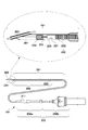
- FIG. 2 is a diagram showing an overall configuration of the probe portion and a cross-sectional configuration of the tip portion.
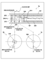
- FIG. 3 is a diagram illustrating a cross-sectional configuration of the imaging core and an arrangement of the ultrasonic transmission / reception unit and the optical transmission / reception unit.
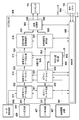
- FIG. 4 is a diagram illustrating a functional configuration of the diagnostic imaging apparatus 100.
- FIG. 5 is a diagram illustrating a functional configuration of the signal processing unit 428 of the diagnostic imaging apparatus 100.
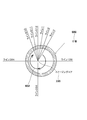
- FIG. 6 is a diagram illustrating a data structure of a generated tomographic image.
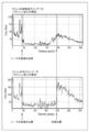
- FIG. 7A is a diagram illustrating an example of ultrasonic line data in line n.
- FIG. 7B is a diagram showing an example of ultrasonic line data in line n when flushing is performed using the flush liquid ⁇ .
- FIG. 7C is a diagram illustrating an example of ultrasonic line data in line n when flushing with the flush liquid ⁇ .
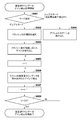
- FIG. 8A is a flowchart showing a flow of ultrasonic line data gain correction processing in the ultrasonic line data correction unit.
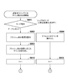
- FIG. 8B is a flowchart showing a flow of ultrasonic line data gain correction processing in the ultrasonic line data correction unit.
- FIG. 8A is a flowchart showing a flow of ultrasonic line data gain correction processing in the ultrasonic line data correction unit.
- FIG. 8B is a flowchart showing a flow of ultrasonic line data gain correction processing in the ultrasonic line data correction
- FIG. 8C is a flowchart showing a flow of ultrasonic line data gain correction processing in the ultrasonic line data correction unit.
- FIG. 9 is a diagram illustrating a data structure of a generated tomographic image.
- FIG. 10A is a diagram illustrating an example of ultrasonic line data in the line 128 when flushing is performed using the flush liquid ⁇ .
- FIG. 10B is a diagram showing an example of ultrasonic line data in the line 384 when the flush liquid ⁇ is used for flushing.
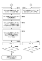
- FIG. 11A is a flowchart showing a flow of ultrasonic line data gain correction processing in the ultrasonic line data correction unit.
- FIG. 11B is a flowchart illustrating a flow of ultrasonic line data gain correction processing in the ultrasonic line data correction unit.
- FIG. 1 is a diagram showing an external configuration of an image diagnostic apparatus (an image diagnostic apparatus having an IVUS function and an OCT function) 100 according to an embodiment of the present invention.
- the diagnostic imaging apparatus 100 includes a probe unit 101, a scanner and pullback unit 102, and an operation control device 103, and the scanner and pullback unit 102 and the operation control device 103 are connected by a signal line 104. Various signals are connected so that transmission is possible.
- the probe unit 101 is directly inserted into a blood vessel (measurement object), transmits an ultrasonic wave based on a pulse signal into the blood vessel, and receives a reflected wave from the blood vessel, and transmitted light.
- An imaging core including an optical transmission / reception unit that continuously transmits (measurement light) into a blood vessel and continuously receives reflected light from the blood vessel is inserted.
- the state inside the blood vessel is measured by using the imaging core.
- the scanner and pullback unit 102 is detachably attached to the probe unit 101, and operates in the axial direction in the blood vessel of the imaging core inserted into the probe unit 101 by driving a built-in motor and the rotational direction around the axis. Is specified. Further, the reflected wave received by the ultrasonic transmission / reception unit and the reflected light received by the optical transmission / reception unit are acquired and transmitted to the operation control apparatus 103.
- the operation control device 103 has a function for inputting various set values and a function for processing data obtained by the measurement and displaying a tomographic image in the blood vessel when performing the measurement.
- 111 is a main body control unit that generates ultrasonic data based on the reflected wave obtained by measurement and processes the ultrasonic line data generated based on the ultrasonic data. Then, an ultrasonic tomographic image is generated. Further, interference light data is generated by causing interference between reflected light obtained by measurement and reference light obtained by separating light from the light source, and an optical line generated based on the interference light data. By processing the data, an optical tomographic image is generated.
- Reference numeral 112 denotes an operation panel, and the user inputs various setting values and instructions via the operation panel 112.
- Reference numeral 113 denotes an LCD monitor as a display device, which displays a tomographic image generated by the main body control unit 111.
- the probe unit 101 includes a long catheter sheath 201 that is inserted into a blood vessel, and a connector that is disposed on the user's hand side without being inserted into the blood vessel to be operated by the user. Part 202.
- a guide wire lumen tube 203 constituting a guide wire lumen is provided at the distal end of the catheter sheath 201.
- the catheter sheath 201 forms a continuous lumen from a connection portion with the guide wire lumen tube 203 to a connection portion with the connector portion 202.
- a transmission / reception unit 221 Inside the lumen of the catheter sheath 201 is provided with a transmission / reception unit 221 in which an ultrasonic transmission / reception unit for transmitting / receiving ultrasonic waves and an optical transmission / reception unit for transmitting / receiving light, an electric signal cable and an optical fiber cable are provided.
- An imaging core 220 including a coil-shaped drive shaft 222 that transmits a rotational drive force for rotating the catheter sheath 201 is inserted over almost the entire length of the catheter sheath 201.
- the connector portion 202 includes a sheath connector 202a configured integrally with the proximal end of the catheter sheath 201, and a drive shaft connector 202b configured by rotatably fixing the drive shaft 222 to the proximal end of the drive shaft 222.
- a kink protector 211 is provided at the boundary between the sheath connector 202a and the catheter sheath 201. Thereby, predetermined rigidity is maintained, and bending (kink) due to a sudden change in physical properties can be prevented.
- the base end of the drive shaft connector 202b is detachably attached to the scanner and the pullback unit 102.
- a housing 223 Inside the lumen of the catheter sheath 201 is a housing 223 in which an ultrasonic transmission / reception unit for transmitting / receiving ultrasonic waves and an optical transmission / reception unit for transmitting / receiving light are arranged, and a rotation for rotating the housing 223
- An imaging core 220 including a driving shaft 222 that transmits a driving force is inserted through substantially the entire length to form the probe unit 101.
- the drive shaft 222 is capable of rotating and axially moving the transmission / reception unit 221 with respect to the catheter sheath 201.
- the drive shaft 222 is made of a metal wire such as stainless steel that is flexible and can transmit rotation well. It is composed of multiple multilayer close-contact coils and the like. An electric signal cable and an optical fiber cable (single mode optical fiber cable) are arranged inside.
- the housing 223 has a shape having a notch in a part of a short cylindrical metal pipe, and is formed by cutting out from a metal lump, MIM (metal powder injection molding) or the like. Further, a short coil-shaped elastic member 231 is provided on the tip side.
- the elastic member 231 is a stainless steel wire formed in a coil shape, and the elastic member 231 is disposed on the distal end side, thereby preventing the imaging core 220 from being caught in the catheter sheath 201 when moving the imaging core 220 back and forth.
- 232 is a reinforcing coil, which is provided for the purpose of preventing a sharp bending of the distal end portion of the catheter sheath 201.
- the guide wire lumen tube 203 has a guide wire lumen into which a guide wire can be inserted.
- the guide wire lumen tube 203 is used to receive a guide wire previously inserted into a blood vessel and guide the catheter sheath 201 to the affected area with the guide wire.
- FIG. 3 is a diagram illustrating a cross-sectional configuration of the imaging core and an arrangement of the ultrasonic transmission / reception unit and the optical transmission / reception unit.
- the transmission / reception unit 221 disposed in the housing 223 includes an ultrasonic transmission / reception unit 310 and an optical transmission / reception unit 320.
- the ultrasonic transmission / reception unit 310 and the optical transmission / reception unit 320 are respectively driven.
- the shaft 222 On the rotation center axis of the shaft 222 (on the alternate long and short dash line on 3a), the shaft 222 is arranged away by a distance L along the axial direction.
- the ultrasonic transmission / reception unit 310 is disposed on the distal end side of the probe unit 101
- the optical transmission / reception unit 320 is disposed on the proximal end side of the probe unit 101.
- the ultrasonic transmission / reception unit 310 and the optical transmission / reception unit 320 include an ultrasonic transmission / reception direction (elevation angle direction) of the ultrasonic transmission / reception unit 310 and an optical transmission / reception direction (elevation angle direction) of the optical transmission / reception unit 320 with respect to the axial direction of the drive shaft 222.
- the ultrasonic transmission / reception unit 310 and the optical transmission / reception unit 320 include an ultrasonic transmission / reception direction (elevation angle direction) of the ultrasonic transmission / reception unit 310 and an optical transmission / reception direction (elevation angle direction) of the optical transmission / reception unit 320 with respect to the axial direction of the drive shaft 222.
- each transmission / reception direction is attached with a slight shift from 90 ° so as not to receive reflection on the inner surface of the lumen of the catheter sheath 201.
- an electric signal cable 311 connected to the ultrasonic transmission / reception unit 310 and an optical fiber cable 321 connected to the optical transmission / reception unit 320 are arranged, and the electric signal cable 311 is an optical fiber.
- the cable 321 is spirally wound.
- 3b in FIG. 3 is a cross-sectional view of the ultrasonic wave transmission / reception position cut along a plane substantially orthogonal to the rotation center axis.
- the ultrasonic transmission / reception direction (circumferential direction (also referred to as azimuth angle direction)) of the ultrasonic transmission / reception unit 310 is ⁇ degrees.
- 3c in FIG. 3 is a cross-sectional view of the optical transmission / reception position taken along a plane substantially orthogonal to the rotation center axis.
- the optical transmission / reception direction (circumferential direction) of the optical transmission / reception unit 320 is 0 degree. That is, the ultrasonic transmission / reception unit 310 and the optical transmission / reception unit 320 have an angle of ⁇ degrees between the ultrasonic transmission / reception direction (circumferential direction) of the ultrasonic transmission / reception unit 310 and the optical transmission / reception direction (circumferential direction) of the optical transmission / reception unit 320. Arranged with a difference.
- FIG. 4 is a diagram illustrating a functional configuration of the diagnostic imaging apparatus 100 that combines the function of IVUS and the function of OCT (here, a wavelength sweep type OCT). Note that the diagnostic imaging apparatus combining the IVUS function and the other OCT functions also has the same functional configuration, and thus the description thereof is omitted here.
- the imaging core 220 includes an ultrasonic transmission / reception unit 310 inside the tip, and the ultrasonic transmission / reception unit 310 transmits ultrasonic waves based on the pulse wave transmitted from the ultrasonic signal transmitter / receiver 452. While transmitting to the biological tissue in the blood vessel, the reflected wave (echo) is received, and it transmits to the ultrasonic signal transmitter / receiver 452 as an ultrasonic signal via the adapter 402 and the slip ring 451.
- the rotational drive unit side of the slip ring 451 is rotationally driven by a radial scanning motor 405 of the rotational drive unit 404. Further, the rotation angle of the radial scanning motor 405 is detected by the encoder unit 406. Further, the scanner and pullback unit 102 includes a linear drive device 407 and defines the axial operation of the imaging core 220 based on a signal from the signal processing unit 428.
- the ultrasonic signal transmitter / receiver 452 includes a transmission wave circuit and a reception wave circuit (not shown).
- the transmission wave circuit transmits a pulse wave to the ultrasonic transmission / reception unit 310 in the imaging core 220 based on the control signal transmitted from the signal processing unit 428.
- the reception wave circuit receives an ultrasonic signal from the ultrasonic transmission / reception unit 310 in the imaging core 220.
- the received ultrasonic signal is amplified by the amplifier 453 and then input to the detector 454 for detection.
- the A / D converter 455 samples the ultrasonic signal output from the detector 454 for 200 points at 30.6 MHz to generate one line of digital data (ultrasonic line data).
- 30.6 MHz is assumed, but this is calculated on the assumption that 200 points are sampled at a depth of 5 mm when the sound speed is 1530 m / sec. Therefore, the sampling frequency is not particularly limited to this.
- the ultrasonic line data for each line generated by the A / D converter 455 is input to the signal processing unit 428.
- the signal processing unit 428 generates an ultrasonic tomographic image at each position in the blood vessel by converting the ultrasonic line data to gray scale, and outputs it to the LCD monitor 113 at a predetermined frame rate.
- the signal processing unit 428 is connected to the motor control circuit 429 and receives the video synchronization signal of the motor control circuit 429.
- the signal processing unit 428 generates an ultrasonic tomographic image in synchronization with the received video synchronization signal.
- the video synchronization signal of the motor control circuit 429 is also sent to the rotation drive device 404, and the rotation drive device 404 outputs a drive signal synchronized with the video synchronization signal.
- Reference numeral 408 denotes a wavelength swept light source (Swept Laser), which is a type of Extended-cavity Laser comprising an SOA 415 (Semiconductor Optical Amplifier) and an optical fiber 416 coupled in a ring shape and a polygon scanning filter (408b).
- Swept Laser a wavelength swept light source
- SOA 415 semiconductor Optical Amplifier
- optical fiber 416 coupled in a ring shape and a polygon scanning filter (408b).
- the light output from the SOA 415 travels through the optical fiber 416 and enters the polygon scanning filter 408b.
- the light whose wavelength is selected here is amplified by the SOA 415 and finally output from the coupler 414.
- the wavelength is selected by a combination of the diffraction grating 412 for separating light and the polygon mirror 409.
- the light split by the diffraction grating 412 is condensed on the surface of the polygon mirror 409 by two lenses (410, 411).
- the wavelength time sweep can be performed by rotating the polygon mirror 409.
- the polygon mirror 409 for example, a 32-hedron mirror is used, and the rotation speed is about 50000 rpm.
- the wavelength sweeping method combining the polygon mirror 409 and the diffraction grating 412 enables high-speed, high-output wavelength sweeping.
- the light of the wavelength swept light source 408 output from the Coupler 414 is incident on one end of the first single mode fiber 440 and transmitted to the distal end side.
- the first single mode fiber 440 is optically coupled to the second single mode fiber 445 and the third single mode fiber 444 at an intermediate optical coupler 441.
- An optical rotary joint (optical cup) that transmits light by coupling a non-rotating part (fixed part) and a rotating part (rotational drive part) to the tip side of the optical coupler part 441 of the first single mode fiber 440.
- a ring portion) 403 is provided in the rotary drive device 404.
- the fifth single mode fiber 443 of the probe unit 101 is detachably connected to the distal end side of the fourth single mode fiber 442 in the optical rotary joint (optical coupling unit) 403 via the adapter 402. Yes.
- the light from the wavelength swept light source 408 is transmitted to the fifth single mode fiber 443 that is inserted into the imaging core 220 and can be driven to rotate.
- the transmitted light is irradiated from the optical transceiver 320 of the imaging core 220 to the living tissue in the blood vessel while rotating and moving in the axial direction. Then, a part of the reflected light scattered on the surface or inside of the living tissue is taken in by the optical transmission / reception unit 320 of the imaging core 220, and returns to the first single mode fiber 440 side through the reverse optical path. Further, a part of the optical coupler unit 441 moves to the second single mode fiber 445 side, and is emitted from one end of the second single mode fiber 445, and then received by a photodetector (eg, a photodiode 424).
- a photodetector eg, a photodiode 424
- rotation drive unit side of the optical rotary joint 403 is rotationally driven by a radial scanning motor 405 of the rotation drive unit 404.
- an optical path length variable mechanism 432 for finely adjusting the optical path length of the reference light is provided at the tip of the third single mode fiber 444 opposite to the optical coupler section 441.
- the optical path length variable mechanism 432 changes the optical path length to change the optical path length corresponding to the variation in length so that the variation in length of each probe unit 101 when the probe unit 101 is replaced and used can be absorbed. Means.
- the third single mode fiber 444 and the collimating lens 418 are provided on a uniaxial stage 422 that is movable in the direction of the optical axis as indicated by an arrow 423, and form optical path length changing means.
- the uniaxial stage 422 when the probe unit 101 is replaced, functions as an optical path length changing unit having a variable range of the optical path length that can absorb variations in the optical path length of the probe unit 101. Further, the uniaxial stage 422 also has a function as an adjusting means for adjusting the offset. For example, even when the tip of the probe unit 101 is not in close contact with the surface of the living tissue, the optical path length is minutely changed by the uniaxial stage so as to interfere with the reflected light from the surface position of the living tissue. Is possible.
- the optical path length is finely adjusted by the uniaxial stage 422, and the light reflected by the mirror 421 via the grating 419 and the lens 420 is first coupled by the optical coupler unit 441 provided in the middle of the third single mode fiber 444. It is mixed with the light obtained from the single mode fiber 440 side and received by the photodiode 424.
- the interference light received by the photodiode 424 in this way is photoelectrically converted, amplified by the amplifier 425, and then input to the demodulator 426.
- the demodulator 426 performs demodulation processing for extracting only the signal portion of the interfered light, and its output is input to the A / D converter 427 as an interference light signal.
- the A / D converter 427 samples the interference light signal for 2048 points at 180 MHz, for example, and generates one line of digital data (interference light data).
- the sampling frequency of 180 MHz is based on the premise that about 90% of the wavelength sweep period (12.5 ⁇ sec) is extracted as 2048 digital data when the wavelength sweep repetition frequency is 80 kHz.
- the present invention is not limited to this.
- the line-by-line interference light data generated by the A / D converter 427 is input to the signal processing unit 428.
- the interference light data is frequency-resolved by FFT (Fast Fourier Transform) to generate data in the depth direction (light line data), and this is coordinate-converted to obtain light at each position in the blood vessel.
- FFT Fast Fourier Transform
- a cross-sectional image is constructed and output to the LCD monitor 113 at a predetermined frame rate.
- the signal processing unit 428 is further connected to the optical path length adjusting means control device 430.
- the signal processing unit 428 controls the position of the uniaxial stage 422 via the optical path length adjusting unit controller 430.
- FIG. 5 is a diagram illustrating a functional configuration of the signal processing unit 428 of the diagnostic imaging apparatus 100 and related functional blocks. Note that the functional configuration shown in FIG. 5 may be realized by using dedicated hardware, or a part thereof is realized by software (that is, when a computer executes a program for realizing the function). May be.
- the interference light data 521 generated by the A / D converter 427 is output from the radial scanning motor 405 output from the motor control circuit 429 in the optical line data generation unit 501 in the signal processing unit 428.
- processing is performed so that the number of lines per rotation is 512.
- the optical line data 522 output from the optical line data generation unit 501 is stored in the optical line data memory 502 for each rotation (one frame) based on an instruction from the control unit 506.
- the control unit 506 counts the pulse signal 541 output from the movement amount detector of the linear drive device 407 and stores the optical line data 522 in the optical line data memory 502, each optical line data The count value at the time of generating 522 is stored in association with each other.
- optical line data 523 stored in association with the count value is input to the optical tomographic image construction unit 504, subjected to various processes (line addition averaging process, filter process, etc.), then subjected to R ⁇ conversion, and sequentially optical tomographic data.
- An image 525 is output.
- the optical line data 524 stored in association with the count value is also input to the lumen position detection unit 503 in parallel, and the lumen position detection unit 503 detects the lumen position for each optical line data. Then, it is input to the ultrasonic line data correction unit 513 as lumen position information.
- the optical tomographic image 525 output from the optical tomographic image construction unit 504 is output to the LCD monitor 113 as an optical tomographic image 526 after image processing for display on the LCD monitor 113 is performed in the image processing unit 505. .
- the ultrasonic data 531 generated by the A / D converter 455 is output from the motor control circuit 429 to the encoder unit 406 of the radial scanning motor 405 in the ultrasonic line data generation unit 511 in the signal processing unit 428. Is processed so that the number of lines per rotation is 512.
- the ultrasonic line data 532 output from the ultrasonic line data generation unit 511 is stored in the ultrasonic line data memory 512 for each rotation (one frame) based on an instruction from the control unit 506.
- the control unit 506 counts the pulse signal 541 output from the movement amount detector of the linear drive device 407 and stores the ultrasonic line data 532 in the ultrasonic line data memory 512.
- the count value at the time of generating the sonic line data 532 is stored in association with each other (note that the count value associated at this time is a count value in consideration of the angle difference ⁇ and the distance L described above. If the count values are the same, it is assumed that the ultrasound line data and the optical line data indicate the same position in the blood vessel).
- the ultrasonic line data 533 stored in association with the count value is input to the ultrasonic line data correction unit 513 and is based on information on the flash liquid (liquid used when performing the flash operation) received from the control unit 506.
- the gain correction is executed (in the control unit 506, gains are preliminarily classified according to the type of the flash solution as information on the flash solution. Note that the gain in the case of blood is also set as a default. It is also memorized together.)
- gain correction is performed on the ultrasound line data corresponding to the outside of the lumen position specified by the lumen position information. Executed (details will be described later).
- the flush liquid information is input by the user via the operation panel 112.
- the operation panel 112 has a dual mode that generates both an ultrasonic tomographic image and an optical tomographic image, and a single mode that generates either an ultrasonic tomographic image or an optical tomographic image.
- One of the modes shall be input.
- the ultrasonic line data 534 whose gain has been corrected by the ultrasonic line data correction unit 513 is input to the ultrasonic tomographic image construction unit 514. Based on an instruction from the control unit 506, the ultrasonic tomographic image construction unit 514 performs various processes (line addition average processing, filter processing, etc.), then R ⁇ conversion, and sequentially forms an ultrasonic tomographic image 535. Is output.
- the image processing unit 505 performs image processing for display on the LCD monitor 113 and outputs the image as an ultrasonic tomographic image 536 to the LCD monitor 113.
- FIG. 6 shows a state in which the imaging core 220 is inserted into the blood vessel 600 as viewed from the cross-sectional direction of the blood vessel 600.
- the imaging core 220 is rotated in the direction of the arrow 602 by the radial scanning motor 405.
- the ultrasonic transmission / reception unit 310 transmits / receives ultrasonic waves at each rotation angle.
- Lines 1, 2,... 512 indicate ultrasonic wave transmission / reception directions at respective rotation angles.
- 512 times of ultrasonic transmission / reception are intermittently performed while the ultrasonic transmission / reception unit 310 rotates 360 degrees in the blood vessel 600. As a result, 512 ultrasonic line data are generated.
- optical transmission / reception unit 320 also continuously transmits / receives 512 times of light while rotating 360 degrees in the blood vessel 600. Thereby, 512 optical line data are generated.
- FIG. 7A shows ultrasonic line data in line n (n is an arbitrary integer from 1 to 512) of ultrasonic line data obtained by transmitting and receiving ultrasonic waves in a state where blood flows in the blood vessel. Show.
- ultrasonic waves have a small attenuation in blood
- ultrasonic waves when ultrasonic waves are transmitted and received in a state where blood flows in a blood vessel, high-intensity ultrasonic signals are received from the vicinity of the lumen position. Can do.
- an ultrasonic signal having a relatively high intensity can be received from inside the vascular tissue (outside the lumen position).
- the upper side of the sheet of FIG. 7B shows the ultrasonic wave in the line n (n is an arbitrary integer from 1 to 512) among the ultrasonic line data obtained by transmitting and receiving ultrasonic waves while the flash liquid ⁇ is flowing. Sonic line data is shown.
- n is an arbitrary integer from 1 to 512
- Data are shown.
- the attenuation of the ultrasonic wave in the flash liquid ⁇ is larger than the attenuation of the ultrasonic wave in the blood, so that the blood is flowing.
- the intensity of the ultrasonic signal received while the flash liquid ⁇ is flowing decreases.
- the upper side of the sheet of FIG. 7C shows line n in the ultrasonic line data obtained by transmitting and receiving ultrasonic waves in a state where the flash liquid ⁇ (a flash liquid different in type from the flash liquid ⁇ ) is flowing.
- the ultrasonic line data in (n is an arbitrary integer from 1 to 512) is shown.
- FIG. 7C shows the optical line in line n (n is an arbitrary integer from 1 to 512) of optical line data obtained by transmitting and receiving light in a state where flash liquid ⁇ is flowing. Data are shown.
- FIG. 7B is compared with FIG. 7C, it is more susceptible than the optical signal of the ultrasonic signal.
- the signal intensity of the ultrasonic line data in the vascular tissue outside the lumen position varies greatly depending on the type of flush liquid.
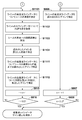
- FIG. 8A is a flowchart showing a flow of ultrasonic line data gain correction processing in the ultrasonic line data correction unit 513.
- a tomographic image generation mode is identified. If the dual mode (a mode for generating both an ultrasonic tomographic image and an optical tomographic image) has been selected in step S801, the process proceeds to step S802.
- step S802 the type of flash liquid is identified, and in step S803, the gain corresponding to the type of flash liquid identified in step S802 is read.
- step S801 if the single mode (the mode for generating only the ultrasonic tomographic image) is selected in step S801, the process proceeds to step S804. In step S804, a default gain is read.
- step S805 “1” is input to the counter n, and in step S806, the ultrasonic line data of the line n (here, line 1) is corrected with the gain read in step S803 or step S804.
- the ultrasonic line data is corrected with a gain corresponding to the type of the flash liquid, and when the blood is flowing, the ultrasonic line data is corrected with a default gain.
- step S807 the counter n is incremented, and in step S808, it is determined whether or not the counter n is greater than 512. If it is determined in step S808 that the counter n is 512 or less, the process returns to step S806, and gain correction is performed on 512 ultrasonic line data forming one frame.
- -An ultrasonic line data correction unit is arranged to perform gain correction for each ultrasonic line data.
- the gain correction the gain value is changed depending on whether the blood is flowing or the flush liquid is flowing. -When the flush liquid is flowing, the gain value is changed according to the type of flush liquid.
- the entire ultrasonic line data is corrected using the gain read in step S803 or step S804.
- the present invention is not limited to this.
- IVUS has a characteristic that it can be measured up to a high depth region, and since ultrasonic line data is important for high depth region data, the gain correction target is limited to the outside of the lumen position (inside the vascular tissue). It is good also as a structure.
- FIG. 8B and 8C are flowcharts showing the flow of ultrasonic line data gain correction processing in the ultrasonic line data correction unit 513 of the diagnostic imaging apparatus 100 according to the present embodiment. Note that the same processes as those in FIG. 8A are denoted by the same reference numerals, and description thereof is omitted here. Hereinafter, the difference from FIG. 8A will be mainly described.
- step S810 “1” is input to the counter n in the dual mode.
- step S811 the position of the outer surface of the sheath is detected for the ultrasonic line data of line n (here, line 1).
- step S812 the lumen position detected by the lumen position detecting unit 503 is acquired for the optical line data of line n (here, line 1).
- line n here, line 1
- the reason why the lumen position is detected from the corresponding optical line data is that the optical line data has a characteristic that the lumen position can be detected more accurately.
- step S813 from the position of the sheath outer surface to the lumen position in the ultrasonic line data of line n (here, line 1) is corrected with a default gain.
- step S814 the outer side of the lumen position in the ultrasonic line data of line n (here, line 1) is corrected with a gain corresponding to the type of the flush liquid.
- step S815 the counter n is incremented, and in step S816, it is determined whether or not the counter n is greater than 512. If it is determined in step S816 that the counter n is 512 or less, the process returns to step S811, and the processing of steps S811 to S815 is repeated for 512 ultrasonic line data forming one frame.
- -An ultrasonic line data correction unit is arranged to perform gain correction for each ultrasonic line data.
- the gain correction the gain value is changed depending on whether the blood is flowing or the flush liquid is flowing.
- the lumen position is detected based on the optical line data.
- the gain from the outer surface of the sheath to the lumen position is corrected with the default gain, and the value outside the lumen position is set according to the type of flush liquid. The configuration is changed.
- the gain value is changed according to the radial position of the imaging core 220 in the blood vessel. Details of this embodiment will be described below.
- FIG. 9 shows a state in which the imaging core 220 is inserted into the blood vessel 600 as viewed from the cross-sectional direction of the blood vessel 600.
- the imaging core 220 is close to the left side of the drawing in the blood vessel 600, the distance from the position of the outer surface of the sheath to the lumen position in the ultrasonic line data of the line 128, The distance from the position of the outer surface of the sheath to the lumen position in the ultrasonic line data is greatly different.
- the ultrasonic wave is significantly attenuated before reaching the lumen position.
- the attenuation of ultrasonic waves until reaching the lumen position is also small.
- FIG. 10A is a diagram showing ultrasonic line data of line 128 and optical line data.
- FIG. 10B is a diagram showing ultrasonic line data and optical line data of the line 384.
- the signal intensity of the ultrasonic line data of the line 128 is smaller than the signal intensity of the ultrasonic line data of the line 384.
- the signal intensity of the optical line data on the line 128 is approximately equal to the signal intensity of the optical line data on the line 384.
- the diagnostic imaging apparatus performs correction while correcting the gain value for each line according to the distance from the position of the outer surface of the sheath to the position of the lumen. Do.
- FIG. 11A is a flowchart showing the flow of ultrasonic line data gain correction processing in the ultrasonic line data correction unit 513 together with FIG. 8B.
- description is abbreviate
- FIG. 11A the same processes as those in FIG. 8C are denoted by the same reference numerals, and description thereof is omitted here.
- FIG. 11A will be described focusing on differences from FIG. 8C.
- step S1101 the position of the outer surface of the sheath is detected for the ultrasonic line data of line n (here, line 1).
- step S1102 the lumen position detected by the lumen position detection unit 503 is acquired for the optical line data of the line n (here, line 1).
- the reason why the lumen position is detected from the corresponding optical line data is that the optical line data has a characteristic that the lumen position can be detected more accurately.
- step S1103 the distance from the outer surface of the sheath to the lumen position is calculated for the ultrasonic line data of line n (here, line 1).
- step S1104 the gain read in step S803 is corrected based on the distance calculated in step S1103.
- a coefficient proportional to the distance calculated in step S1103 is added to the read gain.
- steps S815 and S816 have been described in FIG. 8A, description thereof is omitted here.
- -An ultrasonic line data correction unit is arranged to perform gain correction for each ultrasonic line data.
- the gain correction the gain value is changed depending on whether the blood is flowing or the flush liquid is flowing.
- the lumen position is detected based on the optical line data.
- the gain according to the type of the flush liquid is corrected according to the distance from the position of the outer surface of the sheath to the lumen position, and then used for correction.
- the gain read in step S803 or S804 is corrected according to the distance from the sheath outer surface position to the lumen position, and then the entire ultrasonic line data is corrected.
- the present invention is not limited to this.
- IVUS has a characteristic that it can be measured up to a high depth region, and since ultrasonic line data is important for high depth region data, the gain correction target is limited to the outside of the lumen position (inside the vascular tissue). It is good also as a structure.
- FIG. 11B is a flowchart showing a flow of ultrasonic line data gain correction processing in the ultrasonic line data correction unit 513 of the diagnostic imaging apparatus 100 according to the present embodiment.
- FIG. 11A suppose that the same reference number is attached
- the difference from FIG. 11A will be mainly described.
- step S1111 the ultrasonic line data from the position on the outer surface of the sheath to the lumen position is corrected with the gain read in step S803 or step S804. That is, when the flush liquid is flowing, the ultrasound line data is corrected with a gain corresponding to the type of the flush liquid, and when the blood is flowing, the ultrasound line data is corrected with a default gain.
- step S1112 the ultrasonic line data outside the lumen position is corrected with the gain corrected in step S1104. That is, in the state where the flush liquid is flowing, the gain corresponding to the type of the flush liquid is corrected after being corrected according to the distance from the position of the outer surface of the sheath to the lumen position. In the state where blood is flowing, the default gain is corrected after being corrected according to the distance from the position of the outer surface of the sheath to the position of the lumen.
- -An ultrasonic line data correction unit is arranged to perform gain correction for each ultrasonic line data.
- the gain correction the gain value is changed depending on whether the blood is flowing or the flush liquid is flowing.
- the lumen position is detected based on the optical line data.
- the flush liquid corrects the gain from the position on the outer surface of the sheath to the lumen position with a gain according to the type of flush liquid, and change the type to the flush liquid type outside the lumen position.
- the corresponding gain is corrected according to the distance from the position of the outer surface of the sheath to the lumen position, and then used for correction.
- the generation mode of the tomographic image is identified. You may comprise so that it may judge by identifying that the apparatus act
- the gain value is changed.
- the present invention is not limited to this, and the ultrasonic signal intensity transmitted from the ultrasonic transmission / reception unit 310 may be changed. Good.
Landscapes
- Health & Medical Sciences (AREA)
- Life Sciences & Earth Sciences (AREA)
- Engineering & Computer Science (AREA)
- Medical Informatics (AREA)
- Surgery (AREA)
- Biophysics (AREA)
- Pathology (AREA)
- Veterinary Medicine (AREA)
- Biomedical Technology (AREA)
- Heart & Thoracic Surgery (AREA)
- Public Health (AREA)
- Molecular Biology (AREA)
- Physics & Mathematics (AREA)
- Animal Behavior & Ethology (AREA)
- General Health & Medical Sciences (AREA)
- Nuclear Medicine, Radiotherapy & Molecular Imaging (AREA)
- Radiology & Medical Imaging (AREA)
- Computer Vision & Pattern Recognition (AREA)
- Vascular Medicine (AREA)
- Ultra Sonic Daignosis Equipment (AREA)
- Endoscopes (AREA)
- Cardiology (AREA)
- Physiology (AREA)
Abstract
La présente invention concerne un dispositif de diagnostic par imagerie comportant plusieurs unités d'émission et de réception et générant une image tomographique homogène. La présente invention concerne, donc, un dispositif de diagnostic par imagerie qui, lorsqu'une unité d'émission et de réception dans laquelle sont disposées une première unité d'émission et de réception qui émet et reçoit des signaux ultrasonores et une seconde unité d'émission et de réception qui émet et reçoit des signaux optiques, se déplace dans le sens axial tout en tournant à l'intérieur de la lumière d'un objet devant être mesuré, génère une première image tomographique et une seconde image tomographique de l'intérieur de la lumière de l'objet devant être mesuré à partir des signaux ultrasonores que la première unité d'émission et de réception a émis et reçus et des signaux optiques que la seconde unité d'émission et de réception a émis et reçus. Ledit dispositif de diagnostic par imagerie comprend une unité de commande (506) qui détermine s'il faut générer à la fois la première image tomographique et la seconde image tomographique ou juste la première image tomographique ; et une unité de correction de données de ligne ultrasonore qui modifie le gain lors de la génération de la première image tomographique sur la base des signaux ultrasonores reçus par la première unité d'émission et de réception en fonction de ce qu'aura décidé l'unité de commande (506).
Priority Applications (3)
| Application Number | Priority Date | Filing Date | Title |
|---|---|---|---|
| JP2015509611A JP6001765B2 (ja) | 2013-04-05 | 2013-04-05 | 画像診断装置及びプログラム |
| PCT/JP2013/002385 WO2014162368A1 (fr) | 2013-04-05 | 2013-04-05 | Dispositif de diagnostic par imagerie et programme associé |
| US14/873,638 US11026661B2 (en) | 2013-04-05 | 2015-10-02 | Imaging apparatus for diagnosis and program |
Applications Claiming Priority (1)
| Application Number | Priority Date | Filing Date | Title |
|---|---|---|---|
| PCT/JP2013/002385 WO2014162368A1 (fr) | 2013-04-05 | 2013-04-05 | Dispositif de diagnostic par imagerie et programme associé |
Related Child Applications (1)
| Application Number | Title | Priority Date | Filing Date |
|---|---|---|---|
| US14/873,638 Continuation US11026661B2 (en) | 2013-04-05 | 2015-10-02 | Imaging apparatus for diagnosis and program |
Publications (1)
| Publication Number | Publication Date |
|---|---|
| WO2014162368A1 true WO2014162368A1 (fr) | 2014-10-09 |
Family
ID=51657703
Family Applications (1)
| Application Number | Title | Priority Date | Filing Date |
|---|---|---|---|
| PCT/JP2013/002385 Ceased WO2014162368A1 (fr) | 2013-04-05 | 2013-04-05 | Dispositif de diagnostic par imagerie et programme associé |
Country Status (3)
| Country | Link |
|---|---|
| US (1) | US11026661B2 (fr) |
| JP (1) | JP6001765B2 (fr) |
| WO (1) | WO2014162368A1 (fr) |
Cited By (4)
| Publication number | Priority date | Publication date | Assignee | Title |
|---|---|---|---|---|
| WO2017164070A1 (fr) * | 2016-03-25 | 2017-09-28 | テルモ株式会社 | Dispositif d'imagerie de diagnostic, procédé de commande de dispositif d'imagerie de diagnostic, programme informatique et support d'informations lisible par ordinateur |
| JPWO2017047330A1 (ja) * | 2015-09-18 | 2018-07-05 | テルモ株式会社 | 画像診断用カテーテル |
| JP2021501614A (ja) * | 2017-09-14 | 2021-01-21 | アシスト・メディカル・システムズ,インコーポレイテッド | 血液で満たされているまたは血液が置換された管腔の血管内超音波画像処理 |
| WO2024203754A1 (fr) | 2023-03-28 | 2024-10-03 | テルモ株式会社 | Dispositif de génération d'images tomographiques et système de génération d'images tomographiques |
Families Citing this family (13)
| Publication number | Priority date | Publication date | Assignee | Title |
|---|---|---|---|---|
| EP2488107B1 (fr) | 2009-10-12 | 2017-03-08 | Acist Medical Systems, Inc. | Système ultrasonore intravasculaire pour une imagerie co-enregistrée |
| JP6981967B2 (ja) | 2015-08-31 | 2021-12-17 | ジェンテュイティ・リミテッド・ライアビリティ・カンパニーGentuity, LLC | 撮像プローブおよびデリバリデバイスを含む撮像システム |
| US10909661B2 (en) | 2015-10-08 | 2021-02-02 | Acist Medical Systems, Inc. | Systems and methods to reduce near-field artifacts |
| US11369337B2 (en) | 2015-12-11 | 2022-06-28 | Acist Medical Systems, Inc. | Detection of disturbed blood flow |
| WO2018061672A1 (fr) * | 2016-09-27 | 2018-04-05 | テルモ株式会社 | Dispositif de diagnostic par image, procédé de commande destiné à un dispositif de diagnostic par image, programme informatique, et support d'informations lisible par ordinateur |
| JP6829124B2 (ja) * | 2017-03-22 | 2021-02-10 | テルモ株式会社 | 画像診断装置 |
| US20190082117A1 (en) * | 2017-09-14 | 2019-03-14 | Acist Medical Systems, Inc. | Intravascular ultrasound image processing of blood-filled or blood-displaced lumens |
| WO2019108598A1 (fr) | 2017-11-28 | 2019-06-06 | Gentuity, Llc | Système d'imagerie |
| US12262872B2 (en) | 2018-09-17 | 2025-04-01 | Gentuity, Llc | Imaging system with optical pathway |
| EP3962346A4 (fr) | 2019-04-30 | 2023-04-19 | Gentuity LLC | Sonde d'imagerie dotée d'un élément de mise sous pression de fluide |
| WO2020237024A1 (fr) | 2019-05-21 | 2020-11-26 | Gentuity, Llc | Systèmes et procédés pour un traitement de patients basé sur l'oct |
| US11024034B2 (en) | 2019-07-02 | 2021-06-01 | Acist Medical Systems, Inc. | Image segmentation confidence determination |
| EP4497393A4 (fr) * | 2022-03-31 | 2025-06-25 | Terumo Kabushiki Kaisha | Programme, procédé de traitement d'informations et dispositif de traitement d'informations |
Citations (5)
| Publication number | Priority date | Publication date | Assignee | Title |
|---|---|---|---|---|
| JP2007313202A (ja) * | 2006-05-29 | 2007-12-06 | Fujifilm Corp | 超音波診断システム |
| JP2008511400A (ja) * | 2004-09-02 | 2008-04-17 | ボストン サイエンティフィック リミテッド | 超音波画像診断システムでの自動時間利得補償のシステム |
| JP2010508973A (ja) * | 2006-11-08 | 2010-03-25 | ライトラブ イメージング, インコーポレイテッド | 光−音響イメージングデバイスおよび方法 |
| JP2011200596A (ja) * | 2010-03-26 | 2011-10-13 | Terumo Corp | 光干渉断層像形成装置及びその制御方法 |
| JP2013013439A (ja) * | 2011-06-30 | 2013-01-24 | Terumo Corp | 光干渉断層像形成装置及びその制御方法 |
Family Cites Families (4)
| Publication number | Priority date | Publication date | Assignee | Title |
|---|---|---|---|---|
| US5868666A (en) * | 1993-11-26 | 1999-02-09 | Olympus Optical Co., Ltd. | Endoscope apparatus using programmable integrated circuit to constitute internal structure thereof |
| JP3772002B2 (ja) | 1997-08-28 | 2006-05-10 | オリンパス株式会社 | 被検体内断層イメージング装置 |
| JP4585326B2 (ja) * | 2005-02-08 | 2010-11-24 | 富士フイルム株式会社 | 超音波撮像装置及び超音波撮像方法 |
| US9220415B2 (en) * | 2011-10-25 | 2015-12-29 | Andreas Mandelis | Systems and methods for frequency-domain photoacoustic phased array imaging |
-
2013
- 2013-04-05 JP JP2015509611A patent/JP6001765B2/ja active Active
- 2013-04-05 WO PCT/JP2013/002385 patent/WO2014162368A1/fr not_active Ceased
-
2015
- 2015-10-02 US US14/873,638 patent/US11026661B2/en not_active Expired - Fee Related
Patent Citations (5)
| Publication number | Priority date | Publication date | Assignee | Title |
|---|---|---|---|---|
| JP2008511400A (ja) * | 2004-09-02 | 2008-04-17 | ボストン サイエンティフィック リミテッド | 超音波画像診断システムでの自動時間利得補償のシステム |
| JP2007313202A (ja) * | 2006-05-29 | 2007-12-06 | Fujifilm Corp | 超音波診断システム |
| JP2010508973A (ja) * | 2006-11-08 | 2010-03-25 | ライトラブ イメージング, インコーポレイテッド | 光−音響イメージングデバイスおよび方法 |
| JP2011200596A (ja) * | 2010-03-26 | 2011-10-13 | Terumo Corp | 光干渉断層像形成装置及びその制御方法 |
| JP2013013439A (ja) * | 2011-06-30 | 2013-01-24 | Terumo Corp | 光干渉断層像形成装置及びその制御方法 |
Cited By (7)
| Publication number | Priority date | Publication date | Assignee | Title |
|---|---|---|---|---|
| JPWO2017047330A1 (ja) * | 2015-09-18 | 2018-07-05 | テルモ株式会社 | 画像診断用カテーテル |
| WO2017164070A1 (fr) * | 2016-03-25 | 2017-09-28 | テルモ株式会社 | Dispositif d'imagerie de diagnostic, procédé de commande de dispositif d'imagerie de diagnostic, programme informatique et support d'informations lisible par ordinateur |
| JPWO2017164070A1 (ja) * | 2016-03-25 | 2019-01-31 | テルモ株式会社 | 画像診断装置、画像診断装置の制御方法、コンピュータプログラム、コンピュータ読み取り可能な記憶媒体 |
| US11701003B2 (en) | 2016-03-25 | 2023-07-18 | Terumo Kabishiki Kaisha | Imaging apparatus, method of controlling imaging apparatus, computer program, and computer readable storage medium |
| JP2021501614A (ja) * | 2017-09-14 | 2021-01-21 | アシスト・メディカル・システムズ,インコーポレイテッド | 血液で満たされているまたは血液が置換された管腔の血管内超音波画像処理 |
| WO2024203754A1 (fr) | 2023-03-28 | 2024-10-03 | テルモ株式会社 | Dispositif de génération d'images tomographiques et système de génération d'images tomographiques |
| EP4674358A1 (fr) | 2023-03-28 | 2026-01-07 | Terumo Kabushiki Kaisha | Dispositif de génération d'images tomographiques et système de génération d'images tomographiques |
Also Published As
| Publication number | Publication date |
|---|---|
| JP6001765B2 (ja) | 2016-10-05 |
| US11026661B2 (en) | 2021-06-08 |
| US20160022248A1 (en) | 2016-01-28 |
| JPWO2014162368A1 (ja) | 2017-02-16 |
Similar Documents
| Publication | Publication Date | Title |
|---|---|---|
| JP6001765B2 (ja) | 画像診断装置及びプログラム | |
| JP6125615B2 (ja) | 画像診断装置及びプログラム | |
| JP6117772B2 (ja) | プローブ及び画像診断装置 | |
| JP5981557B2 (ja) | 画像診断装置 | |
| US8157741B2 (en) | Rotational imaging probe safety mechanism for conditional rotational speed reduction | |
| US7905838B2 (en) | Image diagnostic system and apparatus, and processing method therefor | |
| EP2407107B1 (fr) | Dispositif d'imagerie de diagnostic | |
| JP6031089B2 (ja) | プローブ及び画像診断装置 | |
| JP6059334B2 (ja) | 画像診断装置及び情報処理装置及びそれらの作動方法、プログラム及びコンピュータ可読記憶媒体 | |
| JP6055463B2 (ja) | 断層画像生成装置および作動方法 | |
| JP5913607B2 (ja) | 校正冶具、画像診断装置及び画像診断装置の校正方法 | |
| JP6549098B2 (ja) | 制御装置及びその動作方法並びに診断システム | |
| JP6062421B2 (ja) | 画像診断装置及びその作動方法 | |
| WO2014049641A1 (fr) | Dispositif d'imagerie diagnostique, dispositif de traitement de l'information, et procédé de commande de dispositif d'imagerie diagnostique et de dispositif de traitement de l'information |
Legal Events
| Date | Code | Title | Description |
|---|---|---|---|
| 121 | Ep: the epo has been informed by wipo that ep was designated in this application |
Ref document number: 13880730 Country of ref document: EP Kind code of ref document: A1 |
|
| ENP | Entry into the national phase |
Ref document number: 2015509611 Country of ref document: JP Kind code of ref document: A |
|
| NENP | Non-entry into the national phase |
Ref country code: DE |
|
| 122 | Ep: pct application non-entry in european phase |
Ref document number: 13880730 Country of ref document: EP Kind code of ref document: A1 |