WO2014162392A1 - Fil guide - Google Patents
Fil guide Download PDFInfo
- Publication number
- WO2014162392A1 WO2014162392A1 PCT/JP2013/059833 JP2013059833W WO2014162392A1 WO 2014162392 A1 WO2014162392 A1 WO 2014162392A1 JP 2013059833 W JP2013059833 W JP 2013059833W WO 2014162392 A1 WO2014162392 A1 WO 2014162392A1
- Authority
- WO
- WIPO (PCT)
- Prior art keywords
- wire
- plate
- guide wire
- tip
- coil
- Prior art date
- Legal status (The legal status is an assumption and is not a legal conclusion. Google has not performed a legal analysis and makes no representation as to the accuracy of the status listed.)
- Ceased
Links
Images


Classifications
-
- A—HUMAN NECESSITIES
- A61—MEDICAL OR VETERINARY SCIENCE; HYGIENE
- A61M—DEVICES FOR INTRODUCING MEDIA INTO, OR ONTO, THE BODY; DEVICES FOR TRANSDUCING BODY MEDIA OR FOR TAKING MEDIA FROM THE BODY; DEVICES FOR PRODUCING OR ENDING SLEEP OR STUPOR
- A61M25/00—Catheters; Hollow probes
- A61M25/01—Introducing, guiding, advancing, emplacing or holding catheters
- A61M25/09—Guide wires
- A61M2025/09058—Basic structures of guide wires
- A61M2025/09083—Basic structures of guide wires having a coil around a core
- A61M2025/09091—Basic structures of guide wires having a coil around a core where a sheath surrounds the coil at the distal part
-
- A—HUMAN NECESSITIES
- A61—MEDICAL OR VETERINARY SCIENCE; HYGIENE
- A61M—DEVICES FOR INTRODUCING MEDIA INTO, OR ONTO, THE BODY; DEVICES FOR TRANSDUCING BODY MEDIA OR FOR TAKING MEDIA FROM THE BODY; DEVICES FOR PRODUCING OR ENDING SLEEP OR STUPOR
- A61M25/00—Catheters; Hollow probes
- A61M25/01—Introducing, guiding, advancing, emplacing or holding catheters
- A61M25/09—Guide wires
- A61M2025/09108—Methods for making a guide wire
-
- A—HUMAN NECESSITIES
- A61—MEDICAL OR VETERINARY SCIENCE; HYGIENE
- A61M—DEVICES FOR INTRODUCING MEDIA INTO, OR ONTO, THE BODY; DEVICES FOR TRANSDUCING BODY MEDIA OR FOR TAKING MEDIA FROM THE BODY; DEVICES FOR PRODUCING OR ENDING SLEEP OR STUPOR
- A61M25/00—Catheters; Hollow probes
- A61M25/01—Introducing, guiding, advancing, emplacing or holding catheters
- A61M25/09—Guide wires
- A61M2025/0915—Guide wires having features for changing the stiffness
-
- A—HUMAN NECESSITIES
- A61—MEDICAL OR VETERINARY SCIENCE; HYGIENE
- A61M—DEVICES FOR INTRODUCING MEDIA INTO, OR ONTO, THE BODY; DEVICES FOR TRANSDUCING BODY MEDIA OR FOR TAKING MEDIA FROM THE BODY; DEVICES FOR PRODUCING OR ENDING SLEEP OR STUPOR
- A61M25/00—Catheters; Hollow probes
- A61M25/01—Introducing, guiding, advancing, emplacing or holding catheters
- A61M25/09—Guide wires
- A61M2025/09175—Guide wires having specific characteristics at the distal tip
Definitions
- the present invention relates to a guide wire.
- the guide wire introduces and guides catheters used for treatment of difficult surgical sites or treatment for the purpose of minimally invasive to the human body, angiographic examination and treatment in heart disease, etc. Is used.
- the tip of the guide wire is projected from the tip of the balloon catheter under fluoroscopy, and the target site is the target site together with the balloon catheter.
- Insert the coronary artery (coronary artery) just before the stenosis then pass the tip of the guide wire through the stenosis, then guide the balloon catheter balloon along the guide wire to the stenosis, and expand the balloon to stenosis A treatment that spreads the part and secures blood flow is performed.
- the guide wire in order to insert a guide wire from the femoral artery by the Seldinger method and advance to the coronary artery via the aorta, aortic arch, coronary artery mouth, the guide wire has flexibility (followability) to follow the blood vessel, Excellent pushability to transmit the pushing force of the hand part to the tip part, and excellent torque transmission to the extent that the rotational force applied on the proximal side of the guide wire can be reliably transmitted to the tip side.
- followability to follow the blood vessel
- Excellent pushability to transmit the pushing force of the hand part to the tip part
- excellent torque transmission to the extent that the rotational force applied on the proximal side of the guide wire can be reliably transmitted to the tip side.
- it is.
- the guide wire may be shaped into a shape that matches the shape of the branch portion. This shaping is usually performed by a doctor or the like with a finger at the time of treatment, and is called reshaping.
- the desired branch cannot be selected with the conventional pre-shaped angle-shaped or J-shaped distal shape, and the distal end of the guide wire cannot be selected.
- it is changed into a desired shape and reinserted. If the tip shape of the guide wire still does not match, the guide wire must be removed from the catheter, reshaped, and inserted. Therefore, the distal end portion of the guide wire needs to have flexibility as well as reshapability.
- a guide wire in which a flat portion provided at the tip portion has a plate shape in order to obtain flexibility of the tip portion (see, for example, Patent Document 1).
- An object of the present invention is to provide a guide wire that can obtain excellent torque transmission and pushability while ensuring sufficient flexibility at the tip.
- a wire body having a plate-like portion at the tip;
- a guide wire comprising: a reinforcing portion that is provided on at least one surface of the plate-like portion and reinforces the plate-like portion.
- the plate-like portion has a ribbon shape
- the said reinforcement part is a guide wire as described in said (2) or (3) provided on the diagonal of the said plate-shaped part.
- the reinforcing portion is composed of two wires.
- the guide wire according to any one of (2) to (4), wherein the two wire rods are provided on the same plane of the plate-like portion and intersect each other.
- the reinforcing portion is composed of two wires.
- the guide wire according to any one of (2) to (4), wherein the two wire rods are provided on both surfaces of the plate-like portion and intersect each other in plan view.
- the plate-like portion has a ribbon shape
- the said reinforcement part is a guide wire as described in said (1) which has at least 1 wire which extends in a longitudinal direction, and at least 1 wire which extends in the width direction.
- the distal end portion of the guide wire can be easily and surely shaped into a desired shape while ensuring sufficient flexibility at the distal end portion of the guide wire, and is excellent in torque transmission and pushability.
- a guide wire can be provided.
- the wire by providing the wire on at least one surface of the plate-like portion, it is possible to ensure flexibility, torque transmission, and pushability of the distal end portion of the guide wire.
- FIG. 1 is a partial longitudinal sectional view (schematic side view) showing a first embodiment of the guide wire of the present invention.
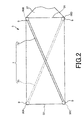
- FIG. 2 is a plan view of a plate-like portion provided in the second embodiment of the guide wire of the present invention.
- FIG. 3 is a plan view of a plate-like portion provided in the third embodiment of the guide wire of the present invention.
- FIG. 1 is a partial longitudinal sectional view (schematic side view) showing a first embodiment of the guide wire of the present invention.
- base end the right side with respect to the longitudinal direction of the guide wire in FIG. 1 is referred to as “base end”
- the left side is referred to as “tip”
- the upper side is “up”
- the lower side is “lower”.
- the length direction of the guide wire is shortened and the radial direction (thickness direction) of the guide wire is exaggerated and schematically illustrated. The ratio of directions is different from the actual ratio (the same applies to FIG. 2 and thereafter).
- the direction in which the guide wire is bent when reshaping is described as the thickness direction of the plate-like portion.
- a guide wire 1 shown in FIG. 1 is a guide wire for a catheter that is used by being inserted into the lumen of a catheter (including an endoscope), and is arranged on the distal end side and has a first wire 2 having a plate-like portion.
- a wire body 10 formed by joining the second wire 4 disposed on the proximal end side of the first wire 2, and a spiral coil 5 installed at the distal end portion (portion on the distal end side) of the wire body 10.
- a reinforcing portion 7 for reinforcing the plate-like portion.
- the total length of the guide wire 1 is not particularly limited, but is preferably about 200 to 5000 mm.
- the first wire 2 is composed of a flexible or elastic wire.
- the first wire 2 has an outer diameter constant portion 21 whose outer diameter is substantially constant, and a first taper that is located on the distal side of the outer diameter constant portion 21 and whose outer diameter gradually decreases in the distal direction.
- a portion 22 a tip-side outer diameter constant portion 26 located on the tip side of the first taper portion 22, and a plate-like transition located further on the tip side, with a thickness decreasing toward the tip direction and a wider width
- a portion 27 a plate-like portion 3 located on the distal end side thereof, a large-diameter portion 24 located on the proximal side from the constant outer diameter portion 21 and having a larger outer diameter than the constant outer diameter portion 21, and a constant outer diameter portion 21 and the large diameter part 24, and has the 2nd taper part 23 in which an outer diameter reduces gradually toward a front-end
- the first taper portion 22 is formed between the plate-like portion 3 and the constant outer diameter portion 21, in particular, the plate-like portion 3 is formed in the vicinity of the tip side of the first taper portion 22,
- the rigidity (bending rigidity, torsional rigidity) of the first wire 2 can be gradually decreased toward the distal end direction.
- the guide wire 1 obtains good narrowness passing characteristics and flexibility at the distal end section.
- followability to blood vessels and the like and safety can be improved, and bending and the like can be prevented.
- the outer diameter constant portion 21 and the large diameter portion 24 are formed via the second taper portion 23, so that the rigidity (bending rigidity, torsional rigidity) of the first wire 2 is achieved. ) Can be gradually decreased toward the tip.
- the taper angle (the reduction rate of the outer diameter) of the first taper portion 22 (the same applies to the second taper portion 23) is constant along the longitudinal direction of the wire body 10, but may vary along the longitudinal direction. May be. For example, a portion in which a taper angle (an outer diameter reduction rate) and a relatively small portion are alternately formed a plurality of times may be used.
- first taper portion 22 and the second taper portion 23 may have different taper shapes and taper angles.
- a plate-like portion 3 having the structure described below is preferably formed integrally with the first taper portion 22 on the tip end side of the first taper portion 22 through a tip-side outer diameter constant portion 26 and a transition portion 27.
- the entire first wire 2 including the plate-like portion 3 is integrally formed of the same material.
- a preferable constituent material of the first wire 2 is a Ni—Ti alloy. It is a representative superelastic alloy (alloy exhibiting pseudoelasticity). Therefore, a preferable constituent material of the plate-like portion 3 is also a superelastic alloy, and this case will be described below.
- the plate-like portion 3 has a plate shape (ribbon shape), and can be used by being deformed into a desired shape (referred to as “reshape or shaping”).
- a doctor or the like previously sets the distal end of the guide wire to a desired shape. In this way, bending the tip of the guide wire into a desired shape is called reshaping.
- reshaping can be performed easily and reliably, and the operativity at the time of inserting the guide wire 1 in a biological body improves markedly.
- the plate width of the plate-like portion 3 is substantially constant along its longitudinal direction.
- the value of the plate width of the plate-like portion 3 is not particularly limited as long as the plate-like portion 3 can be accommodated in the internal space (gap 50) of the coil 5, but to ensure sufficient flexibility and appropriate strength. Therefore, it is preferably about 0.05 to 0.3 mm, more preferably about 0.15 to 0.25 mm.
- board thickness of the plate-shaped part 3 is substantially constant along the longitudinal direction.
- the value of the plate thickness of the plate-like portion 3 is not particularly limited, but is preferably about 0.01 to 0.06 mm, and preferably 0.02 to 0.06 mm in order to ensure sufficient flexibility and appropriate strength. More preferably, it is about 04 mm.
- the outer diameter constant part 26, the constant outer diameter part 21, and the large diameter part 24 have constant outer diameters along the wire longitudinal direction.
- the outer diameter of the tip side outer diameter constant portion 26 is substantially equal to the minimum outer diameter of the first taper portion 22, and the outer diameter of the outer diameter constant portion 21 is substantially equal to the maximum outer diameter of the first taper portion 22. In addition, it is substantially equal to the minimum outer diameter of the second taper portion 23.
- the outer diameter of the large diameter portion 24 is substantially the same as the maximum outer diameter of the second tapered portion 23.
- the distal end of the second wire 4 is joined to the proximal end of the first wire 2 (the proximal end of the large diameter portion 24).
- the second wire 4 is made of a flexible or elastic wire.
- the method for joining the first wire 2 and the second wire 4 is not particularly limited.
- the joining is performed by welding such as friction welding, spot welding using a laser, butting resistance welding such as upset welding, or a tubular joining member.
- butt resistance welding is particularly preferable because it is relatively simple and high joint strength can be obtained.
- the outer diameter of the second wire 4 is substantially constant.
- the outer diameter of the second wire 4 is substantially equal to the outer diameter of the large diameter portion 24 of the first wire 2.
- the average outer diameter of the first wire 2 is smaller than the average outer diameter of the second wire 4.
- the guide wire 1 is highly flexible on the first wire 2 on the distal end side and relatively high on the second wire 4 on the proximal end side. And excellent operability (pushability, torque transmission, etc.).
- the constituent materials of the first wire 2 and the second wire 4 are not particularly limited, and for example, stainless steel (for example, SUS304, SUS303, SUS316, SUS316L, SUS316J1, SUS316J1L, SUS405, SUS430, SUS434, SUS444, SUS429, Various metal materials such as SUS430F, all types of SUS such as SUS302), piano wires, cobalt-based alloys, alloys showing pseudoelasticity (including superelastic alloys) can be used.
- stainless steel for example, SUS304, SUS303, SUS316, SUS316L, SUS316J1, SUS316J1L, SUS405, SUS430, SUS434, SUS444, SUS429
- Various metal materials such as SUS430F, all types of SUS such as SUS302), piano wires, cobalt-based alloys, alloys showing pseudoelasticity (including superelastic alloys) can be used.
- the constituent material of the first wire 2 is preferably an alloy (including a superelastic alloy) exhibiting pseudoelasticity, more preferably a superelastic alloy.
- the guide wire 1 is sufficiently flexible at the tip side by configuring the first wire 2 with the superelastic alloy. Performance and bendability, improved followability to complicatedly curved / bent blood vessels, etc., improved operability, and even if the first wire 2 repeatedly bends / bends, Since the bend crease is not attached due to the resilience of the 1 wire 2, it is possible to prevent the operability from being lowered due to the bend crease on the first wire 2 during use of the guide wire 1.
- Pseudoelastic alloys include any shape of stress-strain curve due to tension, including those where the transformation point of As, Af, Ms, Mf, etc. can be remarkably measured, and those that cannot be measured. However, everything that returns to its original shape by removing stress is included.
- the preferred composition of the superelastic alloy is a Ni—Ti alloy such as a Ni—Ti alloy of 49 to 52 atomic% Ni, a Cu—Zn alloy of 38.5 to 41.5 wt% Zn, 1 to 10 wt% X Cu—Zn—X alloy (X is at least one of Be, Si, Sn, Al, and Ga), Ni-Al alloy of 36 to 38 atomic% Al, and the like.
- X is at least one of Be, Si, Sn, Al, and Ga
- Ni-Al alloy of 36 to 38 atomic% Al, and the like.
- the Ni—Ti alloy is particularly preferable.
- a superelastic alloy typified by a Ni—Ti alloy is also excellent in the adhesion of a resin coating layer 8 described later.
- the cobalt-based alloy has a high elastic modulus when used as a wire and has an appropriate elastic limit. For this reason, the wire comprised by the cobalt type alloy is excellent in torque transferability, and problems, such as buckling, do not arise very much.
- Any cobalt-based alloy may be used as long as it contains Co as a constituent element, but it contains Co as a main component (Co-based alloy: Co content in the elements constituting the alloy) Is preferable, and a Co—Ni—Cr alloy is more preferably used. By using an alloy having such a composition, the above-described effects become more remarkable.
- an alloy having such a composition has a high elastic modulus and can be cold-formed even as a high elastic limit, and by reducing the diameter while sufficiently preventing buckling from occurring due to the high elastic limit. And can have sufficient flexibility and rigidity to be inserted into a predetermined portion.
- the above-mentioned stainless steel is preferable.
- Stainless steel has higher strength and rigidity than the superelastic alloy, and therefore can impart excellent pushability and torque transmission to the guide wire 1.
- the first wire 2 and the second wire 4 may be made of different materials, but may be made of the same or the same kind of metal material (the main metal material in the alloy is the same). In the latter case, the joint strength of the joint portion (welded portion) 6 becomes higher, and even if the outer diameter of the joint portion 6 is small, excellent torque transmission properties and the like are exhibited without causing separation or the like.
- the first wire 2 and the second wire 4 are made of different materials
- the first wire 2 is preferably made of the above-described superelastic alloy, and particularly made of a Ni—Ti alloy.
- the second wire 4 is preferably made of the above-described stainless steel.
- first wire 2 and the second wire 4 are joined.
- first wire 2 and the second wire 4 may be composed of a single continuous wire body without a joint.
- examples of the constituent material of the wire body include the same materials as described above, and stainless steel, cobalt-based alloys, and pseudoelastic alloys are particularly preferable.
- the coil 5 is arranged on the outer periphery of the tip of the wire body 10 so as to cover the tip with the plate-like part 3.
- the installation of the coil 5 reduces the contact area of the surface of the wire body 10 with the inner wall of the catheter and the surface of the living body, thereby reducing the sliding resistance. As a result, the operability of the guide wire 1 is further improved. improves.
- a wire main body 10 is inserted through the central portion inside the coil 5.
- the plate-like portion 3, the transition portion 27, the distal end side outer diameter constant portion 26, the first taper portion 22, and all or part of the outer diameter constant portion 21 are covered with the coil 5. It has been broken.
- the tip end portion (particularly, the region from the plate-like portion 3 to the first taper portion 22) of the wire body 10 is inserted in a non-contact manner with the inner surface of the coil 5. As a result, a gap 50 is formed between the coil 5 and the tip of the wire body 10.
- the coil 5 is formed by spirally forming a strand 54 having a circular cross section.
- one strand 54 may be spirally wound, or a plurality of strands 54 may be spirally wound.
- the constituent material of the strand 54 is not particularly limited, and may be either a metal material or a resin material.
- the metal material include X-ray opaque materials such as stainless steel, noble metals such as Au and Pt, and alloys containing the noble metals (for example, Pt—Ni alloys). In the latter case, X-ray contrast property is obtained at the distal end portion of the guide wire 1, and it can be inserted into the living body while confirming the position of the distal end portion under X-ray fluoroscopy, which is preferable.
- the coil 5 may be a combination of two or more materials.
- the strand 54 on the distal end side of the coil 5 can be made of an X-ray opaque material such as the Pt—Ni alloy, and the strand 54 on the proximal end side of the coil 5 can be made of stainless steel.
- X-ray fluoroscopy it is possible to emphasize the part located on the distal end side of the coil 5 (particularly, the part including the plate-like portion 3) more than the part located closer to the proximal end side. (It becomes easy to visually recognize). Therefore, the position of the most distal portion (portion where the plate-like portion 3 exists) of the guide wire 1 can be visually recognized more clearly.
- the plate-like portion 3, the transition portion 27, the distal-end-side outer diameter constant portion 26, the first portion are not limited to the case where the plate-like portion 3 to the constant outer diameter portion 21 are covered with the coil 5.
- a part of the tapered portion 22 and the constant outer diameter portion 21 may be covered with the coil 5. In this case, it is preferable that at least the outer periphery of the plate-like portion 3 is covered with the coil 5.
- the coil 5 when the coil 5 is installed on the outer periphery of the plate-like portion 3, the coil 5 may be in contact with or in close contact with the plate-like portion 3, and such a coil 5 is a plate of the guide wire 1. It may be installed for the purpose of imparting X-ray contrast properties to a site where the shape portion 3 exists.
- the wire diameter of the wire 54 of the coil 5 may be the same over the entire length of the coil 5, but the wire diameter of the wire 54 may be different between the distal end side and the proximal end side of the coil 5.
- the wire diameter of the strand 54 may be smaller (or larger) on the distal end side of the coil 5 than on the proximal end side.
- the outer diameter of the coil 5 may be the same over the entire length of the coil 5, but the outer diameter of the coil 5 may be different between the distal end side and the proximal end side of the coil 5.
- the outer diameter of the coil 5 may be smaller on the distal end side of the coil 5 than on the proximal end side.
- the adjacent strands 54 of the coil 5 are in contact with each other and are in a so-called dense winding state. These strands 54 generate a force (compression force) that pushes each other in the axial direction of the wire body 10 in a natural state.
- the “natural state” refers to a state where no external force is applied.
- the present invention is not limited to this, and there may be a place where the adjacent strands 54 of the coil 5 are separated from each other.
- the coil 5 is fixed to the wire body 10 at two places (a plurality of places). That is, the distal end portion of the coil 5 is fixed to the distal end of the first wire 2 (the distal end of the plate-like portion 3) by the fixing material 51, and the proximal end portion of the coil 5 is in the middle of the first wire 2 (the outer diameter) by the fixing material 53. It is fixed to the vicinity of the boundary between the fixed portion 21 and the second tapered portion 23. By fixing at such a location, the respective portions of the coil 5 can be reliably fixed to the wire body 10 without impairing the flexibility of the distal end portion (the portion where the coil 5 is present) of the guide wire 1. . Moreover, the plate-shaped part 3 can be reliably fixed with respect to the coil 5, and the shape of the shaped plate-shaped part 3 can be hold
- the fixing materials 51 and 53 are preferably made of solder (brazing material).
- the fixing materials 51 and 53 are not limited to solder and may be adhesives.
- the method for fixing the coil 5 to the wire body 10 is not limited to the above-described fixing material, and for example, welding may be used.
- the distal end surface of the fixing material 51 is preferably rounded (see FIG. 1).
- the outer surface of the guide wire 1 is provided with a resin coating layer 8 covering the whole (or a part thereof).
- the resin coating layer 8 can be formed for various purposes. As an example, the operability of the guide wire 1 is reduced by reducing the friction (sliding resistance) of the guide wire 1 and improving the slidability. May be improved.
- the resin coating layer 8 is preferably made of a material that can reduce friction as described below.
- the frictional resistance (sliding resistance) with the inner wall of the catheter used together with the guide wire 1 is reduced, the slidability is improved, and the operability of the guide wire 1 in the catheter becomes better.
- the sliding resistance of the guide wire 1 is reduced, when the guide wire 1 is moved and / or rotated in the catheter, kinks (bending) or twisting of the guide wire 1, Twist can be prevented more reliably.
- materials that can reduce such friction include polyolefins such as polyethylene and polypropylene, polyvinyl chloride, polyesters (PET, PBT, etc.), polyamides, polyimides, polyurethanes, polystyrenes, polycarbonates, silicone resins, fluorine resins ( PTFE, ETFE, etc.) or a composite material thereof.
- polyolefins such as polyethylene and polypropylene, polyvinyl chloride, polyesters (PET, PBT, etc.), polyamides, polyimides, polyurethanes, polystyrenes, polycarbonates, silicone resins, fluorine resins ( PTFE, ETFE, etc.) or a composite material thereof.
- the resin coating layer 8 can be provided for the purpose of improving safety when the guide wire 1 is inserted into a blood vessel or the like.
- the resin coating layer 8 is made of a flexible material (soft material, elastic material).
- Examples of such flexible materials include polyolefins such as polyethylene and polypropylene, polyvinyl chloride, polyester (PET, PBT, etc.), polyamide, polyimide, polyurethane, polystyrene, silicone resin, polyurethane elastomer, polyester elastomer, polyamide.
- Examples thereof include thermoplastic elastomers such as elastomers, various rubber materials such as latex rubber and silicone rubber, or composite materials in which two or more thereof are combined.
- the resin coating layer 8 is not limited to being entirely composed of the same material, and the constituent material may be different in the middle of the guide wire 1 in the longitudinal direction.
- the material of the portion covering the first wire 2 and the coil 5 of the resin coating layer 8 is made of the flexible material, and the material of the portion covering the second wire 4 of the resin coating layer 8 is the friction. The material can be reduced.
- the resin coating layer 8 may be a single layer or a laminate of two or more layers (for example, an inner layer made of a material that is more flexible than an outer layer).
- the portion of the resin coating layer 8 that covers the first wire 2 and the coil 5 can be a single layer
- the material of the portion of the resin coating layer 8 that covers the second wire 4 can be a laminate of two or more layers. .
- the reverse may be sufficient.
- a groove may be formed on the outer peripheral surface of the resin coating layer 8.
- at least a portion of the resin coating layer 8 corresponding to the plate-like portion 3 (outer peripheral portion of the plate-like portion 3) is formed with a groove having a pattern such as a linear shape, a curved shape, a ring shape, a spiral shape, or a net shape. It is preferable.
- a groove By forming such a groove, the flexibility of the distal end portion of the guide wire 1 is increased, the friction (sliding resistance) of the guide wire 1 is reduced, and the slidability can be further improved.
- a hydrophilic material is coated on the outer surface of at least the tip of the guide wire 1.
- the hydrophilic material is wetted to produce lubricity, the friction (sliding resistance) of the guide wire 1 is reduced, and the slidability is improved. Therefore, the operability of the guide wire 1 is improved.
- hydrophilic materials include cellulose-based polymer materials, polyethylene oxide-based polymer materials, and maleic anhydride-based polymer materials (for example, maleic anhydride copolymers such as methyl vinyl ether-maleic anhydride copolymer).
- Acrylamide polymer substances for example, polyacrylamide, block copolymer of polyglycidyl methacrylate-dimethylacrylamide (PGMA-DMAA)), water-soluble nylon, polyvinyl alcohol, polyvinylpyrrolidone and the like.
- Such a hydrophilic material often exhibits lubricity by wetting (water absorption) and reduces frictional resistance (sliding resistance) with the inner wall of the catheter used together with the guide wire 1. Thereby, the slidability of the guide wire 1 is improved, and the operability of the guide wire 1 in the catheter becomes better.
- a reinforcing portion 7 for reinforcing the plate-like portion 3 is provided on one surface of the plate-like portion 3 of the guide wire 1.
- the reinforcing portion 7 functions as a rigidity imparting portion that imparts rigidity to the plate-like portion 3 rich in flexibility.
- the reinforcing portion 7 has a first wire 71 and a second wire 72 which are linear and are configured separately from the plate-like portion 3.
- the first wire 71 and the second wire 72 each have a circular cross-sectional shape and are provided on the same plane.
- the cross-sectional shapes of the first wire 71 and the second wire 72 are not particularly limited, and may be any shape such as an elliptical shape, a square shape, or a semicircular shape.
- the wire diameter (thickness) of the 1st wire 71 and the 2nd wire 72 is constant along the longitudinal direction.
- Such a first wire 71 is located on a diagonal line connecting the upper left corner 30A in FIG. 1 of the plate-like portion 3 and the lower right corner 30D in FIG. 1 of the plate-like portion 3. Yes.
- the second wire 72 is located on a diagonal line connecting the lower left corner 30C in FIG. 1 of the plate-like portion 3 and the upper right corner 30B of the plate-like portion 3 in FIG.
- first wire rod 71 is fixed to the corner portion 30A, and the proximal end portion of the first wire rod 71 is fixed to the corner portion 30D.
- distal end portion of the second wire rod 72 is fixed to the corner portion 30C, and the proximal end portion of the first wire rod 71 is fixed to the corner portion 30B.
- first wire 71 and the second wire 72 intersect at the central portion of the plate-like portion 3.
- the rotational force transmitted to the base end 31 of the plate-like portion 3 is sufficiently transmitted to the tip of the plate-like portion 3 via the first wire 71 and the second wire 72.
- the second wire 72 is mainly responsible for transmission of the rotational force, and the rotational force is transmitted to the plate-like portion 3 via the second wire 72. Fully transmitted to the tip 32.
- the first wire 71 is mainly responsible for transmission of the rotational force, and the rotational force reaches the tip 32 of the plate-like portion 3 via the first wire 71. Fully communicated. Thereby, the torque transmission property can be ensured sufficiently and reliably to the tip of the guide wire 1.
- the force for pushing from the proximal end portion of the guide wire 1 toward the distal end portion is transmitted. It will be done.
- the pushing force is transmitted to the base end 31 of the plate-like part 3
- the pushing force is transmitted from the base end 31 of the plate-like part 3 toward the tip 32.
- the flexible plate-like portion 3 may be buckled.
- the first wire 71 and the second wire 72 are responsible for transmitting the pushing force.
- the pushing force transmitted to the base end 31 of the plate-like portion 3 is sufficiently transmitted to the tip of the plate-like portion 3 via the first wire 71 and the second wire 72. Therefore, the plate-like part 3 is also excellent in pushability (pushability).
- both end portions of the first wire rod 71 and the second wire rod 72 are fixed to the plate-like portion 3 by the fixing portions 9, respectively.
- portions other than both ends of the first wire 71 and the second wire 72 can be approached and separated from the surface of the plate-like portion 3.
- the first wire 71 and the second wire 72 are not fixed.
- the first wire 71 and the second wire 72 can be independently deformed.
- the first wire 71 and the second wire 72 can be easily deformed following the deformation of the plate-like portion 3. Therefore, it can prevent inhibiting the reshape property of the plate-shaped part 3.
- the lengths of the first wire 71 and the second wire 72 are each preferably 3 to 30 mm, and more preferably 5 to 20 mm. Moreover, in this embodiment, although the length of the 1st wire 71 and the 2nd wire 72 is equal, you may mutually differ.
- the wire diameters of the first wire 71 and the second wire 72 are preferably 0.03 to 0.15 mm, and more preferably 0.05 to 0.1 mm.
- the wire diameters of the first wire 71 and the second wire 72 are constant along the longitudinal direction, but there may be a portion where the wire diameter changes in the middle of the longitudinal direction.
- the wire diameters of the first wire 71 and the second wire 72 are configured to gradually decrease toward the tip, the tip of the plate-like portion 3 becomes more flexible. .
- the material constituting the first wire 71 and the second wire 72 is not particularly limited.
- stainless steel, superelastic alloy, cobalt-based alloy, noble metal such as gold, platinum, tungsten, or an alloy containing these metals. Etc. can be used.
- first wire 71 and the second wire 72 and the plate-like portion 3 may be made of the same material or different materials. In the former case, since the rigidity of the first wire 71 and the second wire 72 and the plate-like portion 3 is equal, it is more excellent in reshapability, torque transmission property and pushability.
- the rigidity of the first wire 71 and the second wire 72 may be higher or lower than the rigidity of the plate-like portion 3.
- the rigidity of the first wire 71 and the second wire 72 is higher than the rigidity of the plate-like portion 3, it is possible to obtain the guide wire 1 that is more excellent in torque transmission and pushability.
- the rigidity of the first wire 71 and the second wire 72 is lower than the rigidity of the plate-like portion 3, the guide wire 1 having more flexibility can be obtained.
- Each of the fixing portions 9 is preferably made of solder (brazing material). Note that the fixing portion 9 is not limited to solder but may be an adhesive. Moreover, the fixing method with respect to the plate-shaped part 3 of the 1st wire 71 and the 2nd wire 72 is not restricted to the above fixing materials, For example, welding may be sufficient.
- the reinforcing portion 7 is provided on one surface of the plate-like portion 3, but may be provided on both surfaces. In this case, the torque transmission property and pushability of the plate-like portion 3 can be further increased.
- first wire 71 and the second wire 72 are not limited to those shown in the drawings, and may have a portion curved in the longitudinal direction, for example.
- FIG. 2 is a plan view of a plate-like portion provided in the second embodiment of the guide wire of the present invention.
- This embodiment is the same as the first embodiment except that the configuration of the reinforcing portion 7 is different.
- the first wire 71 and the second wire 72 are provided on different surfaces of the plate-like portion 3, respectively. Further, the first wire 71 and the second wire 72 have different inclination directions with respect to the axis of the wire body 10 and intersect each other in plan view of the plate-like portion 3.
- the plate-like portion 3 is bent toward the front side of the paper surface in FIG. 2 and the plate-like portion 3 is bent toward the back side of the paper surface in FIG. In this case, the bending rigidity balance is more suitable. Therefore, the plate-like portion 3 of the present embodiment is more excellent in reshapability and operability.
- first wire 71 and the second wire 72 intersect with each other in plan view of the plate-like portion 3, but may be configured to overlap with each other in plan view of the plate-like portion 3. . That is, the first wire 71 and the second wire 72 may be inclined in the same inclination direction with respect to the axis of the wire body 10.
- FIG. 3 is a plan view of a plate-like portion provided in the third embodiment of the guide wire of the present invention.
- This embodiment is the same as the second embodiment except that the configuration of the plate-like portion 3 is different.
- the reinforcing portion 7 of the present embodiment includes a first reinforcing portion 70 ⁇ / b> A that extends in the longitudinal direction of the plate-like portion 3 and a second reinforcement that extends in the width direction of the plate-like portion 3. Part 70B.
- the first reinforcing portion 70A is mainly responsible for improving the pushability of the guide wire 1.
- the first reinforcing portion 70A is composed of a wire rod 71A and a wire rod 71B provided along the edge of the plate-like portion 3 facing in the width direction.
- the distal end portion of the wire rod 71A is fixed to the corner portion 30A, and the base end portion is fixed to the corner portion 30B.
- the base end portion of the wire 71B is fixed to the corner portion 30C, and the base end portion is fixed to the corner portion 30D.
- the second reinforcing portion 70B has four wire rods 72A, 72B, 72C, 72D provided at equal intervals in the longitudinal direction of the plate-like portion 3. Wires 72A, 72B, 72C, 72D are provided in this order from the tip side.
- the second reinforcing portion 70B is mainly responsible for enhancing the torque transmission performance of the guide wire 1.
- the wire rod 72 ⁇ / b> A is provided along the edge located at the tip of the plate-like portion 3.
- the upper end portion of the wire rod 72A is fixed to the corner portion 30A together with the tip portion of the wire rod 71A.
- the lower end part of wire rod 72A is being fixed to corner
- the wire 72B is provided in the middle of the plate-shaped portion 3 in the longitudinal direction.
- the upper end portion of the wire rod 72B is fixed to the edge portion on the upper end side of the plate-like portion 3 along the middle of the wire rod 71A in the longitudinal direction.
- the lower end part of the wire 72B is being fixed to the edge part by the side of the lower end of the plate-shaped part 3 with the part in the middle of the longitudinal direction of the wire 71B.
- the wire rod 72 ⁇ / b> C is provided in the middle of the plate-like portion 3 in the longitudinal direction.
- the upper end portion of the wire rod 72C is fixed to the edge portion on the upper end side of the plate-like portion 3 along the longitudinal direction of the wire rod 71A.
- the lower end portion of the wire rod 72C is fixed to the edge portion on the lower end side of the re-plate-like portion 3 together with the middle portion of the wire rod 71B in the longitudinal direction.
- the wire rod 72 ⁇ / b> D is provided along the edge located at the base end of the plate-like portion 3.
- the upper end portion of the wire rod 72D is fixed to the corner portion 30B together with the base end portion of the wire rod 71A.
- the lower end part of wire rod 72D is being fixed to corner
- the wires 71A, 71B, 72A, 72B, 72C, 72D arranged in this way have a ladder shape in plan view of the plate-like portion 3.
- the rotational force when a rotational force is applied to the proximal end portion of the guide wire 1, the rotational force is transmitted from the proximal end side toward the distal end side of the guide wire 1 in the order of the second wire 4 and the first wire 2.
- the rotational force is transmitted to the base end 31 of the plate-like portion 3, the rotational force is more sufficiently and reliably supplied to the tip of the plate-like portion 3 via the wire rods 71A, 71B, 72A, 72B, 72C and 72D. Communicated.
- the force for pushing from the proximal end portion of the guide wire 1 toward the distal end portion is transmitted. It will be done.
- the pushing force is transmitted to the base end 31 of the plate-like part 3
- the pushing force is transmitted from the base end 31 of the re-plate-like part 3 toward the tip 32.
- the pushing force transmitted to the base end 31 of the plate-like portion 3 is sufficiently transmitted to the tip of the plate-like portion 3 through the wire rods 71A, 71B, 72A, 72B, 72C and 72D. Therefore, the plate-like portion 3 is more excellent in pushability (pushability).
- the reinforcement part is comprised with the wire, in this invention, it is not limited to this, For example, you may be comprised with the member which makes
- the reinforcing portion and the plate-like portion are configured as separate bodies from each other, but may be integrally formed. In this case, the step of fixing the reinforcing portion to the plate-like portion can be omitted.
- the guide wire according to the present invention includes a wire body having a plate-like portion at a distal end portion, and a reinforcing portion that is provided on at least one surface of the plate-like portion and reinforces the plate-like portion. .
- the distal end portion of the guide wire can be easily and surely shaped into a desired shape while ensuring sufficient flexibility at the distal end portion of the guide wire, and is excellent in torque transmission and pushability.
- a guide wire can be provided.
- the guide wire of the present invention has industrial applicability.
Landscapes
- Health & Medical Sciences (AREA)
- Life Sciences & Earth Sciences (AREA)
- Biophysics (AREA)
- Pulmonology (AREA)
- Engineering & Computer Science (AREA)
- Anesthesiology (AREA)
- Biomedical Technology (AREA)
- Heart & Thoracic Surgery (AREA)
- Hematology (AREA)
- Animal Behavior & Ethology (AREA)
- General Health & Medical Sciences (AREA)
- Public Health (AREA)
- Veterinary Medicine (AREA)
- Media Introduction/Drainage Providing Device (AREA)
Abstract
L'invention concerne un fil guide (1) présentant : un corps principal (10) de fil présentant, en une extrémité correspondante, une partie en forme de plaque (3) ; et des parties de renforcement (7) qui sont situées sur au moins une surface de la partie en forme de plaque (3) et qui renforcent la partie en forme de plaque (3). Les parties de renforcement (7) sont conçues à partir de deux éléments de fil, les extrémités de chacun desdits éléments de fil étant fixées sur la partie en forme de plaque (3). En outre, la partie en forme de plaque (3) présente une forme de ruban. Les parties de renforcement (7) sont situées respectivement en diagonale et de manière coplanaire sur la partie en forme de plaque (3) et se croisent. Ce fil guide (1) est doté d'une bobine (5) qui couvre à la fois la partie en forme de plaque (3) et les parties de renforcement (7).
Priority Applications (3)
| Application Number | Priority Date | Filing Date | Title |
|---|---|---|---|
| PCT/JP2013/059833 WO2014162392A1 (fr) | 2013-04-01 | 2013-04-01 | Fil guide |
| JP2015509630A JP5997370B2 (ja) | 2013-04-01 | 2013-04-01 | ガイドワイヤ |
| US14/864,441 US9808604B2 (en) | 2013-04-01 | 2015-09-24 | Guide wire |
Applications Claiming Priority (1)
| Application Number | Priority Date | Filing Date | Title |
|---|---|---|---|
| PCT/JP2013/059833 WO2014162392A1 (fr) | 2013-04-01 | 2013-04-01 | Fil guide |
Related Child Applications (1)
| Application Number | Title | Priority Date | Filing Date |
|---|---|---|---|
| US14/864,441 Continuation US9808604B2 (en) | 2013-04-01 | 2015-09-24 | Guide wire |
Publications (1)
| Publication Number | Publication Date |
|---|---|
| WO2014162392A1 true WO2014162392A1 (fr) | 2014-10-09 |
Family
ID=51657726
Family Applications (1)
| Application Number | Title | Priority Date | Filing Date |
|---|---|---|---|
| PCT/JP2013/059833 Ceased WO2014162392A1 (fr) | 2013-04-01 | 2013-04-01 | Fil guide |
Country Status (3)
| Country | Link |
|---|---|
| US (1) | US9808604B2 (fr) |
| JP (1) | JP5997370B2 (fr) |
| WO (1) | WO2014162392A1 (fr) |
Cited By (1)
| Publication number | Priority date | Publication date | Assignee | Title |
|---|---|---|---|---|
| WO2025046678A1 (fr) * | 2023-08-28 | 2025-03-06 | 朝日インテック株式会社 | Tige de dispositif médical et dispositif médical |
Families Citing this family (2)
| Publication number | Priority date | Publication date | Assignee | Title |
|---|---|---|---|---|
| US12048820B2 (en) * | 2019-08-14 | 2024-07-30 | Vasoinnovations Inc. | Apparatus and method for advancing catheters or other medical devices through a lumen |
| JP7702358B2 (ja) * | 2019-12-27 | 2025-07-03 | 朝日インテック株式会社 | ガイドワイヤ |
Citations (2)
| Publication number | Priority date | Publication date | Assignee | Title |
|---|---|---|---|---|
| JPH07500022A (ja) * | 1991-06-21 | 1995-01-05 | スミスズ インダストリーズ メディカル システムズ,インコーポレイテッド | 気管切開管と閉塞具の組合せ |
| JP2007501648A (ja) * | 2003-08-07 | 2007-02-01 | ブリヴァント リサーチ アンド デベロップメント リミテッド | カテーテルに使用するガイドワイヤ |
Family Cites Families (13)
| Publication number | Priority date | Publication date | Assignee | Title |
|---|---|---|---|---|
| US5042475A (en) | 1988-09-30 | 1991-08-27 | Portex, Inc. | Hinged tracheostomy tube obturator |
| CA1313101C (fr) | 1988-09-30 | 1993-01-26 | Denis Labombard | Obturateur a charniere pour canule de tracheostomie |
| JP3460849B2 (ja) * | 1994-01-31 | 2003-10-27 | 日本ゼオン株式会社 | 医療器具 |
| US20030069522A1 (en) * | 1995-12-07 | 2003-04-10 | Jacobsen Stephen J. | Slotted medical device |
| GB9617545D0 (en) * | 1996-08-21 | 1996-10-02 | Smiths Industries Ltd | Medical tube assemblies |
| GB9908136D0 (en) * | 1999-04-12 | 1999-06-02 | Smiths Industries Plc | Obturators and tube assemblies |
| JP2002017862A (ja) * | 2000-07-12 | 2002-01-22 | Nippon Sherwood Medical Industries Ltd | オブチュレーター |
| JP4028245B2 (ja) * | 2002-01-28 | 2007-12-26 | テルモ株式会社 | ガイドワイヤ |
| EP1581293B1 (fr) * | 2002-12-20 | 2009-09-09 | Brivant Research & Development Limited | Fil-guide utilise avec un catheter |
| JP2009233200A (ja) * | 2008-03-27 | 2009-10-15 | Terumo Corp | ガイドワイヤ |
| JP2011110384A (ja) * | 2009-11-30 | 2011-06-09 | Patentstra Co Ltd | 医療用ガイドワイヤ、その製造方法、及び医療用ガイドワイヤとマイクロカテーテル、又はバルーンカテーテルとガイディングカテーテルとの組立体 |
| CN102753231B (zh) * | 2010-02-05 | 2015-07-15 | 泰尔茂株式会社 | 导丝 |
| JP5229830B2 (ja) | 2010-06-25 | 2013-07-03 | 朝日インテック株式会社 | 医療用ガイドワイヤ |
-
2013
- 2013-04-01 JP JP2015509630A patent/JP5997370B2/ja active Active
- 2013-04-01 WO PCT/JP2013/059833 patent/WO2014162392A1/fr not_active Ceased
-
2015
- 2015-09-24 US US14/864,441 patent/US9808604B2/en not_active Expired - Fee Related
Patent Citations (2)
| Publication number | Priority date | Publication date | Assignee | Title |
|---|---|---|---|---|
| JPH07500022A (ja) * | 1991-06-21 | 1995-01-05 | スミスズ インダストリーズ メディカル システムズ,インコーポレイテッド | 気管切開管と閉塞具の組合せ |
| JP2007501648A (ja) * | 2003-08-07 | 2007-02-01 | ブリヴァント リサーチ アンド デベロップメント リミテッド | カテーテルに使用するガイドワイヤ |
Cited By (1)
| Publication number | Priority date | Publication date | Assignee | Title |
|---|---|---|---|---|
| WO2025046678A1 (fr) * | 2023-08-28 | 2025-03-06 | 朝日インテック株式会社 | Tige de dispositif médical et dispositif médical |
Also Published As
| Publication number | Publication date |
|---|---|
| JPWO2014162392A1 (ja) | 2017-02-16 |
| US20160008586A1 (en) | 2016-01-14 |
| US9808604B2 (en) | 2017-11-07 |
| JP5997370B2 (ja) | 2016-09-28 |
Similar Documents
| Publication | Publication Date | Title |
|---|---|---|
| JP5020630B2 (ja) | ガイドワイヤ | |
| JP6082807B2 (ja) | ガイドワイヤ | |
| JP4981471B2 (ja) | ガイドワイヤ | |
| JP5770676B2 (ja) | ガイドワイヤ | |
| JP2008245852A (ja) | ガイドワイヤ | |
| JP2004230141A (ja) | ガイドワイヤ | |
| JP6759069B2 (ja) | ガイドワイヤ | |
| JP2008237253A (ja) | ガイドワイヤ | |
| JP5214878B2 (ja) | ガイドワイヤ | |
| JP5473677B2 (ja) | ガイドワイヤ | |
| JP5997370B2 (ja) | ガイドワイヤ | |
| JP2018079246A (ja) | ガイドワイヤ | |
| JP5931479B2 (ja) | ガイドワイヤ | |
| JP4783343B2 (ja) | ガイドワイヤ | |
| JPWO2016047555A1 (ja) | ガイドワイヤおよびガイドワイヤの製造方法 | |
| JP5328835B2 (ja) | ガイドワイヤの製造方法 | |
| JP3962652B2 (ja) | ガイドワイヤ | |
| WO2014162389A1 (fr) | Fil guide | |
| JP6347632B2 (ja) | ガイドワイヤ | |
| JP2009202030A (ja) | ガイドワイヤ | |
| WO2014162391A1 (fr) | Fil-guide | |
| JP5019868B2 (ja) | ガイドワイヤ | |
| JP2017164039A (ja) | ガイドワイヤ | |
| JP5135452B2 (ja) | ガイドワイヤ | |
| JP4783345B2 (ja) | ガイドワイヤ |
Legal Events
| Date | Code | Title | Description |
|---|---|---|---|
| 121 | Ep: the epo has been informed by wipo that ep was designated in this application |
Ref document number: 13881322 Country of ref document: EP Kind code of ref document: A1 |
|
| ENP | Entry into the national phase |
Ref document number: 2015509630 Country of ref document: JP Kind code of ref document: A |
|
| NENP | Non-entry into the national phase |
Ref country code: DE |
|
| 122 | Ep: pct application non-entry in european phase |
Ref document number: 13881322 Country of ref document: EP Kind code of ref document: A1 |