WO2014162479A1 - Manipulateur médical - Google Patents
Manipulateur médical Download PDFInfo
- Publication number
- WO2014162479A1 WO2014162479A1 PCT/JP2013/059985 JP2013059985W WO2014162479A1 WO 2014162479 A1 WO2014162479 A1 WO 2014162479A1 JP 2013059985 W JP2013059985 W JP 2013059985W WO 2014162479 A1 WO2014162479 A1 WO 2014162479A1
- Authority
- WO
- WIPO (PCT)
- Prior art keywords
- handle
- drive unit
- stopper
- medical manipulator
- state
- Prior art date
- Legal status (The legal status is an assumption and is not a legal conclusion. Google has not performed a legal analysis and makes no representation as to the accuracy of the status listed.)
- Ceased
Links
Images


Classifications
-
- A—HUMAN NECESSITIES
- A61—MEDICAL OR VETERINARY SCIENCE; HYGIENE
- A61B—DIAGNOSIS; SURGERY; IDENTIFICATION
- A61B90/00—Instruments, implements or accessories specially adapted for surgery or diagnosis and not covered by any of the groups A61B1/00 - A61B50/00, e.g. for luxation treatment or for protecting wound edges
- A61B90/03—Automatic limiting or abutting means, e.g. for safety
-
- A—HUMAN NECESSITIES
- A61—MEDICAL OR VETERINARY SCIENCE; HYGIENE
- A61B—DIAGNOSIS; SURGERY; IDENTIFICATION
- A61B17/00—Surgical instruments, devices or methods
- A61B17/28—Surgical forceps
- A61B17/29—Forceps for use in minimally invasive surgery
-
- A—HUMAN NECESSITIES
- A61—MEDICAL OR VETERINARY SCIENCE; HYGIENE
- A61B—DIAGNOSIS; SURGERY; IDENTIFICATION
- A61B18/00—Surgical instruments, devices or methods for transferring non-mechanical forms of energy to or from the body
- A61B18/04—Surgical instruments, devices or methods for transferring non-mechanical forms of energy to or from the body by heating
- A61B18/12—Surgical instruments, devices or methods for transferring non-mechanical forms of energy to or from the body by heating by passing a current through the tissue to be heated, e.g. high-frequency current
- A61B18/14—Probes or electrodes therefor
- A61B18/1442—Probes having pivoting end effectors, e.g. forceps
- A61B18/1445—Probes having pivoting end effectors, e.g. forceps at the distal end of a shaft, e.g. forceps or scissors at the end of a rigid rod
-
- A—HUMAN NECESSITIES
- A61—MEDICAL OR VETERINARY SCIENCE; HYGIENE
- A61B—DIAGNOSIS; SURGERY; IDENTIFICATION
- A61B17/00—Surgical instruments, devices or methods
- A61B2017/00017—Electrical control of surgical instruments
- A61B2017/00199—Electrical control of surgical instruments with a console, e.g. a control panel with a display
-
- A—HUMAN NECESSITIES
- A61—MEDICAL OR VETERINARY SCIENCE; HYGIENE
- A61B—DIAGNOSIS; SURGERY; IDENTIFICATION
- A61B17/00—Surgical instruments, devices or methods
- A61B17/00234—Surgical instruments, devices or methods for minimally invasive surgery
- A61B2017/00292—Surgical instruments, devices or methods for minimally invasive surgery mounted on or guided by flexible, e.g. catheter-like, means
- A61B2017/003—Steerable
- A61B2017/00305—Constructional details of the flexible means
- A61B2017/00314—Separate linked members
-
- A—HUMAN NECESSITIES
- A61—MEDICAL OR VETERINARY SCIENCE; HYGIENE
- A61B—DIAGNOSIS; SURGERY; IDENTIFICATION
- A61B17/00—Surgical instruments, devices or methods
- A61B2017/00367—Details of actuation of instruments, e.g. relations between pushing buttons, or the like, and activation of the tool, working tip, or the like
- A61B2017/00398—Details of actuation of instruments, e.g. relations between pushing buttons, or the like, and activation of the tool, working tip, or the like using powered actuators, e.g. stepper motors, solenoids
-
- A—HUMAN NECESSITIES
- A61—MEDICAL OR VETERINARY SCIENCE; HYGIENE
- A61B—DIAGNOSIS; SURGERY; IDENTIFICATION
- A61B17/00—Surgical instruments, devices or methods
- A61B2017/0046—Surgical instruments, devices or methods with a releasable handle; with handle and operating part separable
-
- A—HUMAN NECESSITIES
- A61—MEDICAL OR VETERINARY SCIENCE; HYGIENE
- A61B—DIAGNOSIS; SURGERY; IDENTIFICATION
- A61B17/00—Surgical instruments, devices or methods
- A61B17/28—Surgical forceps
- A61B17/29—Forceps for use in minimally invasive surgery
- A61B17/2909—Handles
- A61B2017/291—Handles the position of the handle being adjustable with respect to the shaft
-
- A—HUMAN NECESSITIES
- A61—MEDICAL OR VETERINARY SCIENCE; HYGIENE
- A61B—DIAGNOSIS; SURGERY; IDENTIFICATION
- A61B17/00—Surgical instruments, devices or methods
- A61B17/28—Surgical forceps
- A61B17/29—Forceps for use in minimally invasive surgery
- A61B2017/2926—Details of heads or jaws
- A61B2017/2927—Details of heads or jaws the angular position of the head being adjustable with respect to the shaft
-
- A—HUMAN NECESSITIES
- A61—MEDICAL OR VETERINARY SCIENCE; HYGIENE
- A61B—DIAGNOSIS; SURGERY; IDENTIFICATION
- A61B90/00—Instruments, implements or accessories specially adapted for surgery or diagnosis and not covered by any of the groups A61B1/00 - A61B50/00, e.g. for luxation treatment or for protecting wound edges
- A61B90/03—Automatic limiting or abutting means, e.g. for safety
- A61B2090/033—Abutting means, stops, e.g. abutting on tissue or skin
- A61B2090/034—Abutting means, stops, e.g. abutting on tissue or skin abutting on parts of the device itself
-
- A—HUMAN NECESSITIES
- A61—MEDICAL OR VETERINARY SCIENCE; HYGIENE
- A61B—DIAGNOSIS; SURGERY; IDENTIFICATION
- A61B90/00—Instruments, implements or accessories specially adapted for surgery or diagnosis and not covered by any of the groups A61B1/00 - A61B50/00, e.g. for luxation treatment or for protecting wound edges
- A61B90/08—Accessories or related features not otherwise provided for
- A61B2090/0803—Counting the number of times an instrument is used
-
- A—HUMAN NECESSITIES
- A61—MEDICAL OR VETERINARY SCIENCE; HYGIENE
- A61B—DIAGNOSIS; SURGERY; IDENTIFICATION
- A61B90/00—Instruments, implements or accessories specially adapted for surgery or diagnosis and not covered by any of the groups A61B1/00 - A61B50/00, e.g. for luxation treatment or for protecting wound edges
- A61B90/08—Accessories or related features not otherwise provided for
- A61B2090/0814—Preventing re-use
Definitions
- the present invention relates to a medical manipulator having a drive source.
- endoscopic surgery also called laparoscopic surgery
- a trocar tubular instrument
- a laparoscope camera
- a plurality of forceps are inserted into the body cavity through the one or more trocars.
- a gripper, a scissors, a blade of an electric knife, and the like are attached to the distal end portion of the forceps as an end effector for gripping a living tissue or the like.
- the operation is performed by operating the forceps while observing the inside of the abdominal cavity reflected on the monitor connected to the laparoscope. Since such an operation method does not require laparotomy, the burden on the patient is small, and the number of days until recovery and discharge from the operation is greatly reduced. For this reason, such an operation method is expected to expand the application field.
- a medical manipulator in which part or all of the operation of the distal end working unit is performed by a drive source (motor) has been proposed (for example, JP, A 2008-104854).
- a motor as a drive source is mounted on a handle provided with an operation button, and a working portion (a portion corresponding to forceps) including a distal end working portion and a shaft can be attached to and detached from the handle. It has become.
- working units such as a needle driver and an electric knife, and different types of working units can be selectively attached to and detached from the handle.
- the handle to be used is common to the different types of end effectors.
- the shape of the handle is different for each type of end effector, operability can be improved.
- a handle having a different shape including a drive source is prepared for each working unit having different types of end effectors, there is a problem that the cost of the medical manipulator increases.
- a configuration in which a common drive unit can be mounted on a manipulator body (forceps portion) including a handle configured in an appropriate shape according to the type of end effector is adopted.
- a manipulator body forceps portion
- a handle configured in an appropriate shape according to the type of end effector
- the manipulator body is provided with various power transmission parts (for example, gears, wires, etc.).
- these power transmission parts are deteriorated with use. Occurs. For this reason, it is desirable to provide a certain limit on the number of times the manipulator body is used.
- an object of the present invention is to provide a medical manipulator that can improve operability without providing a drive source for each handle and can limit the number of times the manipulator body is used.
- a medical manipulator of the present invention includes a manipulator body having a handle, a detachable to the handle, a drive unit including a drive source, a handle provided on the handle, A number-of-times limiting mechanism that prevents the drive unit from being attached to the handle when the number of attachments / detachments of the drive unit reaches a set number.
- the drive unit when the number of attachments / detachments of the drive unit to / from the handle reaches the set number (the manipulator body use limit number), the drive unit cannot be attached to the handle due to the action of the number limit mechanism. That is, the use of the manipulator body exceeding the usage limit number can be forcibly limited.
- the drive unit including the drive source is detachable from the handle, it is not necessary to provide a drive source for each handle having a different function and shape. That is, the medical manipulator of the present invention can be used by attaching a common drive unit to a handle configured in an appropriate shape according to the type of end effector. Therefore, good operability can be obtained without increasing the cost of the manipulator.
- the number limiting mechanism includes an operating body that is mechanically interlocked with attachment / detachment of the drive unit to / from the handle, and a counting mechanism that operates a predetermined amount each time the operating body is operated, and the counting mechanism is in an initial state. When the operation is performed for the set number of times, mounting of the drive unit to the handle may be prevented.
- the actuating body mechanically interlocked with the attachment / detachment of the drive unit and the counting mechanism are provided, the number of attachments / detachments is reliably counted. It can be activated reliably.
- the number-of-times limiting mechanism has a stopper that changes to a restricted state when the counting mechanism operates the set number of times from the initial state, and the stopper is configured to handle the drive unit in the restricted state. You may protrude on the movement path
- the number-of-times limiting mechanism includes a lock member that is displaced to a restriction position when the count mechanism operates the set number of times from the initial state, and the lock member is at the restriction position, The movement may be prevented.
- the operating body When the drive unit is attached to the handle, the operating body is pushed by the drive unit and displaced from the first position to the second position, and the drive unit is removed from the handle. Accordingly, the slider may return from the second position to the first position.
- the operating body configured as a slider moves forward and backward as the drive unit is attached to and detached from the handle. Therefore, it is possible to mechanically reliably detect the attachment / detachment of the drive unit and operate the counting mechanism.
- It may have an operating body urging means for urging the operating body toward the first position.
- the operating body can be reliably returned to the first position when the drive unit is removed from the handle. Therefore, the count mechanism can be reliably operated by a predetermined amount each time the drive unit is attached or detached.
- the number limiting mechanism is operable from a non-restricted state to a restricted state, and has a stopper that protrudes on a movement path of the drive unit when the drive unit is attached to the handle in the restricted state
- the count mechanism includes an intermediate transmission mechanism that is driven by the operation of the operating body and a rotating body that is rotated by the intermediate transmission mechanism, and the rotating body is in a state where the number of attachments / detachments is less than the set number of times. Then, the stopper may be locked and held in the non-restricted state, and the change of the stopper to the restricted state may be allowed in a state where the number of attachments / detachments has reached the set number of times.
- the movement of the operating body that operates by attaching and detaching the drive unit is transmitted to the rotating body via the intermediate transmission mechanism.
- the stopper is protruded on the moving path of the drive unit. Even if an attempt is made to mount the drive unit to the handle in this state, the drive unit is physically blocked because the drive unit is caught by the stopper. Therefore, it is possible to reliably prevent the use of the manipulator body exceeding the use limit number of times.
- Each of the operating body, the intermediate transmission mechanism, and the rotating body is configured by a plate-like member, and the stopper may change from the non-regulated state to the regulated state with an inclination operation from an initial posture. Good.
- the number limiting mechanism can be thinned and the installation volume in the handle can be reduced. Therefore, an increase in the size of the handle accompanying the provision of the number limiting mechanism can be suitably suppressed.
- the intermediate transmission mechanism may include a plurality of gears that mesh with each other.
- the amount of rotation of the rotating body according to the amount of displacement of the operating body when the drive unit is attached to or detached from the handle can be adjusted by the gear ratio of the gear. Therefore, the set number of times for activating the attachment prevention function can be easily set by adjusting the gear ratio.
- the number limiting mechanism includes a stopper urging member that urges the stopper toward the restricted state, the rotating body is provided with a notch, and the number of times of attachment / detachment is less than the set number of times,
- the stopper is held in the non-regulated state against the urging force of the stopper urging member, and the number of attachments / detachments is equal to the set number of times. In this state, the contact body provided on the stopper may be able to enter the notch.
- the stopper is not operated when the number of attachments / detachments is less than the set number, and the stopper can be reliably operated when the set number is reached.
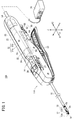
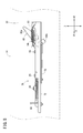
- FIG. 1 is a partially omitted perspective view of a medical manipulator according to an embodiment of the present invention.
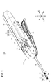
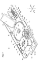
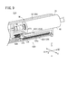
- FIG. 2 is a partially omitted perspective view of a manipulator body in the medical manipulator shown in FIG. 1. It is a perspective view of the drive unit in the medical manipulator shown in FIG. It is a perspective view of a frequency limiting mechanism. It is a disassembled perspective view of a frequency limiting mechanism. It is a figure of the state which the slider advanced in the frequency limiting mechanism.
- FIG. 6 is a perspective view of a state where a mounting prevention function is activated in the number limiting mechanism.
- FIG. 11 is a side view of a state where a mounting prevention function is activated in the number limiting mechanism.
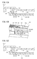
- FIG. 11A is a schematic cross-sectional view of the number limiting mechanism according to the modified example when the drive unit is mounted
- FIG. 11B illustrates the operation of the second claw member when the rack member moves forward in the number limiting mechanism according to the modified example
- FIG. 11C is a second diagram for explaining the operation of the second claw member when the rack member moves forward in the number limiting mechanism according to the modified example
- FIG. 12A is a schematic cross-sectional view for explaining the operation of the number limiting mechanism according to the modification example when the drive unit is removed, and FIG.
- FIG. 12B is the second claw member of the number limiting mechanism according to the modification example when the drive unit is removed.
- FIG. 12C is a diagram illustrating the operation of the first claw member of the number limiting mechanism according to the modification when the drive unit is removed. It is a typical perspective view which shows the structural example which provided the gear member in the frequency
- FIG. 14A is a schematic cross-sectional view illustrating a configuration example in which a lock member is provided in the number limiting mechanism according to the modified example
- FIG. 14B is a schematic diagram illustrating a state in which the lock member is activated in the number limiting mechanism according to the modified example. It is sectional drawing. It is a partially-omission perspective view of the medical manipulator concerning other embodiments of the present invention.
- FIG. 16 is a partially omitted perspective view of the manipulator body in the medical manipulator shown in FIG. 15.
- FIG. 1 is a partially omitted perspective view of a medical manipulator 10A (hereinafter abbreviated as “manipulator 10A”) according to an embodiment of the present invention.
- the manipulator 10A is a medical device for holding a needle, a thread, or a part of a living body with a gripper 12 (end effector) provided at the tip or touching the living body to perform a predetermined treatment.
- the manipulator 10 ⁇ / b> A drives a handle 14 provided with a plurality of input operation units, a shaft 16 extending from the handle 14, a tip operating unit 18 including a gripper 12 provided at the tip of the shaft 16, and the tip operating unit 18. And a drive unit 22 that is provided with a motor 20 (drive source) to be attached to and detachable from the handle 14.
- the handle 14, the shaft 16, and the distal end working unit 18 constitute a manipulator body 11 ⁇ / b> A.
- the X direction in the figure is the front-rear direction
- the Y direction is the left-right direction
- the Z direction is the up-down direction.
- the X1 direction is the front and the X2 direction is the rear.
- the manipulator body 11A and the drive unit 22 are detachable. In a state where the drive unit 22 is removed from the manipulator body 11A (see FIG. 2), the driving force of the motor 20 is not transmitted to the distal end working unit 18. On the other hand, when the motor 20 is driven with the drive unit 22 attached to the handle 14, the driving force of the motor 20 is transmitted to the distal end working unit 18.
- the manipulator 10A shown in FIG. 1 is configured as a needle driver in which the gripper 12 at the tip can hold a medical needle (curved needle or the like).
- the gripper 12 is a part for performing a surgical procedure.
- the gripper 12 includes first and second gripper members 12a and 12b, and is configured to open and close based on a predetermined opening and closing operation axis Og.
- the gripper 12 is configured such that the first gripper member 12a is configured as a fixed portion and the second gripper member 12b is configured as a movable portion, but both gripper members 12a and 12b are configured as movable portions. Also good.
- the tip operating unit 18 including the gripper 12 can be changed in posture with respect to the shaft 16 with a plurality of degrees of freedom.
- the distal end working unit 18 tilts left and right with respect to the axis of the shaft 16 with respect to the tilting axis Oy, and the longitudinal axis of the distal end working unit 18 (swing motion). It is possible to perform a “roll operation” that rotates about the roll axis Or).
- the tilt axis Oy is not limited to being set in the vertical direction, and may be set in another direction that intersects the axis of the shaft 16.
- the shaft 16 is a long and thin tubular member, and connects the handle 14 and the distal end working unit 18. In FIG. 1, a part of the shaft 16 is omitted and is drawn shorter than the actual one.
- the hollow portion of the shaft 16 is provided with a power transmission mechanism for transmitting power necessary for opening / closing the gripper 12 and roll operation and tilting operation of the distal end working unit 18 from the handle 14 side to the distal end working unit 18.
- a plurality of constituent members are inserted and arranged.
- the shaft 16 may be configured such that one or more joints are provided in the middle of the longitudinal direction of the shaft 16 and the tilting operation can be performed at the joints. Moreover, the roll operation
- movement may be comprised in the middle part of the longitudinal direction of the shaft 16, or the base end part of the shaft 16.
- the handle 14 is gripped by an operator when the manipulator 10A is used, and is operated by touching an input operation unit (in this embodiment, a tilting wheel 26, a roll switch 28, and a lever 30 described later) with fingers. This is a portion that drives the distal end working portion 18 connected to the distal end portion of the shaft 16.
- an input operation unit in this embodiment, a tilting wheel 26, a roll switch 28, and a lever 30 described later
- the handle 14 includes a body portion 24 to which the base end of the shaft 16 is connected, a tilting wheel 26 that is provided on the body portion 24 and forms a tilt operation portion, and a roll that is provided on the body portion 24 and forms a roll operation portion.
- a switch 28 and a lever 30 provided in the body portion 24 and constituting an opening / closing operation portion are provided.
- the body portion 24 is a portion that is gripped by the user when the manipulator 10 is used.
- the trunk portion 24 is configured in a stick shape extending slightly longer in the axial direction of the shaft 16.
- the body portion 24 includes a housing 32 composed of a left cover 32a and a right cover 32b, and a frame, driving components (pulleys, gears, wires, etc.) and the like are disposed in the housing 32.
- a mounting hole 33 opened rearward is formed in order to insert and mount the drive unit 22 from the rear.
- the tilting wheel 26 for tilting the distal end working unit 18 is provided in the vicinity of the longitudinal center of the body unit 24 so as to be rotatable about the vertical axis of the handle 14.
- the tilting wheel 26 is configured as a manual operation unit, and the tilting wheel 26 is partially exposed from the openings 27 provided on the left and right sides of the housing 32.
- the tilting wheel 26 When the tilting wheel 26 is rotationally operated, the operating force is mechanically transmitted to the tip operating unit 18 via the power transmission system for tilting operation provided in the handle 14 and the shaft 16, and the tip operating unit 18 is It tilts around an axis (inclination axis Oy) in a direction non-parallel to the axis of the shaft 16. Specifically, when the tilting wheel 26 is rotated clockwise in plan view, the distal end working unit 18 tilts to the right with reference to the handle 14, and when the tilting wheel 26 is rotated counterclockwise in plan view. The distal end working unit 18 tilts leftward with respect to the handle 14.
- the roll switch 28 for causing the tip operating portion 18 to roll is provided on the upper portion of the body portion 24 near the tip.
- the roll switch 28 is configured as an electric operation unit that gives an operation command to the motor 20 via the controller 36.
- the drive unit 22 When the drive unit 22 is attached to the handle 14 and the controller 36 is turned on, if the roll switch 28 is operated and moved, the operation state (position) of the roll switch 28 is detected by the controller 36, and the controller The motor 20 is driven under the control action of 36, and the driving force of the motor 20 is transmitted to the distal end working unit 18, so that the distal end working unit 18 sets the longitudinal axis of the distal end working unit 18 (roll axis Or). Rotates as the center.
- a lever 30 for opening and closing the gripper 12 is provided at the lower portion of the body portion 24 so as to be swingable up and down with the tip side as a fulcrum.
- the lever 30 is configured as a manual operation unit, and the operation force on the lever 30 is mechanically transmitted to the gripper 12 of the distal end working unit 18, so that the gripper 12 is opened and closed.
- the gripper 12 is opened with the lever 30 opened, and the gripper 12 is closed when the lever 30 is closed.
- the manipulator 10 ⁇ / b> A is used in a state where the drive unit 22 is connected to the controller 36 via a cable 54.
- the controller 36 supplies power to the motor 20 and controls driving, and receives power from an external power source.
- the controller 36 controls the driving of the motor 20 in accordance with the operation.
- the rotation of the motor 20 may be detected and feedback control may be performed through the controller 36.
- the manipulator 10A configured as described above is discarded after being used a predetermined number of times for the manipulator body 11A, while the drive unit 22 is used many times by changing the connected manipulator body 11A. Can be taken.
- FIG. 3 is a perspective view of the drive unit 22.
- the drive unit 22 includes a housing 48, a motor 20 (drive source) disposed in the housing 48, and a drive coupling 50 (drive member) fixed to the output shaft 21 of the motor 20.
- a cable 54 including a power line and a signal line is connected to the base end side of the drive unit 22.
- the drive coupling 50 fixed to the output shaft 21 of the motor 20 is a driven coupling (driven member) (not shown) provided on the handle 14 side. To fit (mesh).
- the motor 20 is driven in a state where the drive coupling 50 and the driven coupling are fitted, the rotational driving force of the motor 20 is transmitted to the handle 14 side via the drive coupling 50 and the driven coupling.
- the handle 14 is provided with a guide rail 56 extending along the longitudinal direction (front-rear direction) of the handle 14.
- guide rails 56 are provided on both the left and right sides of the inner surface of the housing 32.
- groove-shaped guide receiving portions 58 extending along the longitudinal direction of the drive unit 22 are provided on the left and right side surfaces of the housing 48.
- the guide rail 55 and the guide receiving portion 58 constitute a guide mechanism 55 (see FIG. 1).
- the drive unit 22 can be smoothly moved with respect to the handle 14 under the action of the guide mechanism 55. Therefore, the drive unit 22 can be reliably and easily attached to the handle 14 with an accurate positional relationship.
- the handle 14 is provided with a handle side terminal.
- the drive unit 22 is provided with a unit side terminal. In a state where the drive unit 22 is attached to the handle 14, the handle side terminal and the unit side terminal are in contact with each other. With this configuration, the operation state of the roll switch 28 is detected by the controller 36, and the controller 36 can appropriately drive and control the motor 20.
- the drive unit 22 is provided with a lock mechanism 60 that restricts the drive unit 22 from being detached from the handle 14 in a state where the drive unit 22 is attached to the handle 14.
- the lock mechanism 60 of the illustrated example includes an engaging portion 62 provided on the handle 14 and a lever device 64 provided on the drive unit 22.
- the lever device 64 includes a lever device 64, an operation tab 68, and a lever urging member (not shown).
- the lever member 66 can swing with respect to the housing 48 and is provided with an engaging claw 67.
- the operation tab 68 is provided at the base end of the lever member 66.
- the lever urging member elastically urges the lever member 66 toward the protruding direction of the engaging claw 67 (downward in the illustrated example).
- the engagement claw 67 provided on the lever member 66 engages with the engagement portion 62 provided in the handle 14, thereby driving the handle 14. The separation of the unit 22 is prevented. On the other hand, when the engagement between the engagement claw 67 of the lever member 66 and the engagement portion 62 is released, the drive unit 22 can be detached from the handle 14.
- the handle 14 is further provided with a number limiting mechanism 70.
- the number limiting mechanism 70 prevents the drive unit 22 from being attached to the handle 14 when the number of times the drive unit 22 is attached to or detached from the handle 14 reaches a set number.
- the set number of times is a use limit number of the manipulator body 11A.
- the case where the drive unit 22 is attached / detached once to / from the manipulator body 11A is regarded as one use of the manipulator body 11A.
- the set number of times that the mounting of the drive unit 22 is prevented can be arbitrarily set, but is set, for example, in the range of 10 to 50 times.
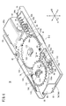
- FIG. 4 is a perspective view of the number limiting mechanism 70 according to one configuration example
- FIG. 5 is an exploded perspective view of the number limiting mechanism 70.
- the number limiting mechanism 70 includes a frame 72, an operating body 74 that can slide in the front-rear direction with respect to the frame 72, an intermediate transmission mechanism 76 that is linked to the operating body 74, A rotating body 78 that is rotated by the intermediate transmission mechanism 76 and a stopper 80 that can be changed between a non-restricted state and a restricted state and that prevents the drive unit 22 from being attached to the handle 14 in the restricted state.
- the frame 72 has a frame main body 82 and a cover body 84 fixed to the frame main body 82, and is fixed at a predetermined position in the handle 14.
- the frame main body 82 in the illustrated example has a substantially rectangular shape in plan view.
- An operating body 74, an intermediate transmission mechanism 76, a rotating body 78, and a stopper 80 are arranged on the frame 72.
- the cover body 84 is fixed to the frame main body 82 by appropriate fixing means 85 (screws in the illustrated example). Both the frame main body 82 and the cover body 84 can be manufactured by sheet metal processing, for example.
- the frame main body 82 and the cover body 84 may be made of resin.
- the operating body 74 is mechanically interlocked with the attachment / detachment of the drive unit 22 with respect to the handle 14. Specifically, the actuating body 74 is pushed by the drive unit 22 as the drive unit 22 is attached to the handle 14 and is displaced from the retracted position (first position) to the advanced position (second position). To do. Further, the operating body 74 returns from the forward movement position to the backward movement position as the drive unit 22 is removed from the handle 14. In FIG. 4, the actuator 74 is in the retracted position.
- the operating body 74 of the illustrated example is configured as a slider 74A that moves forward and backward as the drive unit 22 is attached to and detached from the handle 14.
- the operating body 74 has a flat plate-like base portion 86 that contacts the frame main body 82 and is slidable along the frame main body 82, and a pressed portion 88 that protrudes from the base portion 86.
- the base 86 is provided with a plurality of (two in the illustrated example) elongated hole-shaped guide holes 90a and 90b extending in the front-rear direction.
- Guide pins 92a and 92b are fixed to the frame body 82, and the guide pins 92a and 92b are inserted into the guide holes 90a and 90b.
- the guide pins 92a and 92b are prevented from coming out of the guide holes 90a and 90b.
- the operating body 74 can slide stably with respect to the frame 72 in the front-rear direction (X direction) by the guide action by the engagement between the guide holes 90a, 90b and the guide pins 92a, 92b.
- the pressed portion 88 is a portion that is pressed by the drive unit 22 as the drive unit 22 moves when the drive unit 22 is attached to the handle 14.
- the pressed portion 88 is provided to bend at the tip of the base 86 and protrude upward.
- the pressed portion 88 may be provided integrally with the base 86, or may be a member attached to the base 86.
- the operating body 74 is elastically biased toward the retracted position by a return spring 94 (operating body biasing means).
- a return spring 94 operating body biasing means
- one end 94 a of the return spring 94 is engaged with a hook piece 75 provided on the operating body 74
- the other end 94 b of the return spring 94 is engaged with a hook piece 73 provided on the frame 72.
- the return spring 94 urges the operating body 74 backward (X2 direction) with respect to the frame 72 by an elastic action to be contracted.
- the return spring 94 may be configured and arranged so as to urge the operating body 74 rearward with respect to the frame 72 by an elastic action to be extended.
- the intermediate transmission mechanism 76 includes a claw member 98 that is displaced together with the operating body 74, a ratchet wheel 100 that is driven by the claw member 98, a first gear 102 that is coupled to the ratchet wheel 100, and a second gear that meshes with the first gear 102. And a gear 104.
- the claw member 98 is formed in a plate shape and is supported by a shaft portion 117 fixed to the base portion 86, and can rotate (swing) around the shaft portion 117 within a predetermined angle range with respect to the operating body 74. It is. By attaching a locking part 118 (C clip in the illustrated example) to the shaft portion 117, the claw member 98 is prevented from coming off from the shaft portion 117.
- the claw member 98 is provided with an engagement claw 98 a that can be engaged with the ratchet wheel 100, and a contact protrusion 98 b that can contact a locking piece 99 provided on the base 86.
- the claw member 98 is elastically urged in the direction A in FIG. 5 by the claw urging member 108.
- the claw urging member 108 in the illustrated example is in the form of a torsion spring, but may be a spring of another form such as a coil spring or may be constituted by an elastic member other than the spring.
- the claw member 98 is prevented from further rotating in the A direction.
- the claw member 98 receives a predetermined force or more in the B direction opposite to the A direction, the claw member 98 can rotate in the B direction against the elastic force of the claw urging member 108. It is.
- the ratchet wheel 100 is provided to be rotatable with respect to the frame 72 via the shaft portion 101.
- the ratchet wheel 100 of the illustrated example is configured in a relatively thin flat plate shape.
- a latching component 119 (C clip in the illustrated example) is attached to the shaft portion 101 to prevent the ratchet wheel 100 and the first gear 102 from coming off from the shaft portion 101.
- the shaft portion 101 is fixed to the cover body 84 by a fixing component 97 (in the illustrated example).
- the teeth 100 a provided on the outer periphery of the ratchet wheel 100 can be engaged with the engaging claws 98 a of the claw member 98.
- a latch member 114 provided on the frame main body 82 is engaged with the teeth 100 a of the ratchet wheel 100.
- the latch member 114 is fixed to the frame main body 82 by fixing means 116 (screws in the illustrated example).
- the latch member 114 is provided with an elastically displaceable latch piece 115.
- the latch piece 115 engages with the teeth 100a of the ratchet wheel 100 so as to allow the ratchet wheel 100 to rotate in the C direction while preventing the ratchet wheel 100 from rotating in the direction opposite to the C direction. That is, the ratchet wheel 100 can rotate only in the C direction.
- the first gear 102 is arranged coaxially with the ratchet wheel 100.
- the second gear 104 in the illustrated example is configured in a relatively thin flat plate shape.
- the ratchet wheel 100 and the first gear 102 are fixed to each other so as not to be relatively rotatable.
- the two holding pins 103 are inserted into and engaged with both the ratchet wheel 100 and the first gear 102 so that the ratchet wheel 100 and the first gear 102 are not relatively rotatable. .
- the first gear 102 rotates integrally with the ratchet wheel 100. Therefore, like the ratchet wheel 100, the first gear 102 can rotate only in the C direction.
- the second gear 104 is provided to be rotatable with respect to the frame 72 via the shaft portion 105.
- the second gear 104 in the illustrated example is configured in a relatively thin flat plate shape.
- a locking part 133 C clip in the illustrated example
- the teeth 102 a provided on the outer peripheral portion of the first gear 102 mesh with the teeth 104 a provided on the outer peripheral portion of the second gear 104. Accordingly, the second gear 104 rotates in the D direction about the shaft portion 105 as the first gear 102 rotates in the C direction.
- a ring-shaped spacer 113 is disposed between the second gear 104 and the frame body 82.
- the rotating body 78 is arranged coaxially with the second gear 104 and is arranged on the lower surface side of the frame body 82 in the illustrated example. Further, the rotating body 78 in the illustrated example is configured in a relatively thin flat plate shape.
- the second gear 104 and the rotating body 78 are fixed to each other via the shaft portion 105 so as not to be relatively rotatable, and the rotating body 78 rotates integrally with the second gear 104.
- the rotating body 78 has a disk shape larger in diameter than the second gear 104, and a notch 79 is provided in a part of the outer peripheral portion in the circumferential direction.
- the ratchet wheel 100, the first gear 102, the second gear 104, and the rotating body 78 described above constitute a counting mechanism 112 that operates a predetermined amount each time the operating body 74 is operated.
- the stopper 80 operates from a non-restricted state (the state shown in FIG. 4) that allows the drive unit 22 to be attached to the handle 14 to a restricted state (the position shown in FIG. 7) that prevents the drive unit 22 from being attached to the handle 14.
- the stopper 80 in the illustrated example is rotatably supported by a shaft portion 77 inserted into a stopper support member 81 fixed to the frame 72 (frame body 82).
- a locking part 134 (C clip in the illustrated example) is attached to the shaft part 77, thereby preventing the shaft part 77 from coming off from the stopper support member 81.
- the stopper 80 is in a “non-restricted state” when it is tilted substantially parallel to the frame main body 82, and is a “restricted state” when it occurs at a certain tilt angle with respect to the frame main body 82.
- the stopper 80 protrudes on the movement path (inside the mounting hole 33) of the drive unit 22 when the drive unit 22 is mounted on the handle 14 in the restricted state.
- the stopper 80 is provided with a contact body 80b that can be engaged with the rotating body 78.
- the abutting body 80 b in the illustrated example protrudes downward from the distal end side of the stopper 80 and is inserted into a hole 82 a provided in the frame main body 82.
- the stopper 80 is always urged elastically by the stopper urging member 110 in the direction of the restricted state.
- the stopper urging member 110 in the illustrated example is configured by a leaf spring disposed between the stopper 80 and the stopper support member 81, but may be configured by a spring of another form such as a coil spring. The elastic member other than the spring may be used.
- the stopper 80 is kept in a non-regulated state against the elastic force (biasing force) of the stopper urging member 110.
- the position (phase) of the notch 79 of the rotating body 78 coincides with the abutment 80b, whereby the abutment 80b enters the notch 79.
- the stopper 80 tilts and changes to a restricted state.
- the stay member 135 is fixed to the lower part of the frame body 82.
- the stay member 135 supports a portion of the rotating body 78 that is pressed by the contact body 80b from below. Since the rotating body 78 is supported from below by the stay member 135, the rotating body 78 does not tilt even when the contact body 80b presses the rotating body 78.
- the stay member 135 is provided with a notch 135a that allows the contact body 80b to enter.
- the notch 135 a is provided at a position corresponding to the hole 82 a of the frame main body 82. Thereby, when the notch 79 of the rotating body 78 comes to the position of the contact body 80b, the change of the stopper 80 from the non-regulated state to the regulated state is not hindered.
- the manipulator 10A according to the present embodiment is basically configured as described above, and the operation and effect will be described next.
- the number limiting mechanism 70 is in the initial state shown in FIG.
- the notch 79 provided in the rotating body 78 is in the direction in which the rotating body 78 can rotate from the contact body 80b of the stopper 80 by the amount corresponding to the set number of times (the number of times of use limit). It is in a position shifted in the opposite direction to the (D direction).
- the contact body 80b is locked by the rotating body 78, and the stopper 80 is held in a collapsed state, that is, an unregulated state.
- the operating body 74 is held in the retracted position by the elastic force of the return spring 94.
- the pressed portion 88 of the operating body 74 is caused by a part of the drive unit 22 (for example, the front end portion of the housing 48). It is pressed forward (X1 direction). Thereby, as shown in FIG. 6, the operating body 74 moves to the advance position. As the operating body 74 advances, the claw member 98 provided on the operating body 74 also advances. The engaging claw 98 a of the claw member 98 that moves forward pushes the teeth 100 a of the ratchet wheel 100. As a result, the ratchet wheel 100 is rotated in the C direction by one tooth. When the ratchet wheel 100 rotates, the latch piece 115 gets over the teeth 100a of the ratchet wheel 100 by one tooth with elastic deformation.
- the first gear 102 also rotates in the C direction.
- the second gear 104 that meshes with the first gear 102 rotates in the D direction
- the rotating body 78 that is coaxially connected to the second gear 104 also rotates in the D direction.
- the notch 79 provided in the rotating body 78 is displaced by a predetermined amount in the D direction.
- the contact body 80b of the stopper 80 remains in contact with the outer peripheral portion of the rotating body 78, so that the stopper 80 is still held in an unregulated state.
- the operating body 74 When removing the drive unit 22 from the handle 14, the operating body 74 returns to the retracted position. That is, as the drive unit 22 moves rearward (X2 direction), the pressing of the pressed unit 88 by the drive unit 22 is released, so that the operating body 74 is moved rearward by the elastic force of the return spring 94. . As the actuating body 74 moves rearward, the teeth 100a of the ratchet wheel 100 are pushed backward by the claw member 98 provided on the actuating body 74. However, the latching action of the latch piece 115 causes the ratchet wheel 100 to move in the C direction. Rotation in the opposite direction is prevented. For this reason, when the operating body 74 moves backward, the notch 79 provided in the rotating body 78 does not return to the original position.
- the claw member 98 rotates in the B direction against the elastic force of the claw urging member 108 in the A direction, so that the teeth 100a of the ratchet wheel 100 are equivalent to one tooth. Just get over.
- the engaging claw 98a of the claw member 98 gets over the tooth 100a of the ratchet wheel 100 by one tooth, the claw member 98 is rotated in the A direction by the elastic force of the claw urging member 108, and the contact protrusion 98b. It stops at the position where the locking piece 99 comes into contact.
- the above operation is repeated each time the drive unit 22 is attached to and detached from the handle 14 until a predetermined set number of times (the number of times the manipulator body 11A is used) is reached. Therefore, every time the drive unit 22 is attached or detached, the notch 79 provided in the rotating body 78 moves by a predetermined amount in the C direction.
- the drive unit 22 is repeatedly attached to and detached from the handle 14, and when the number of attachments / detachments reaches the set number of times and the notch 79 reaches the position of the contact body 80b of the stopper 80, the displacement restriction on the stopper 80 by the rotating body 78 is performed. Is released. Accordingly, as the contact body 80b enters the notch 79, the stopper 80 rises obliquely and reaches a restricted state, as shown in FIGS. In FIG. 8, the stopper 80 in the non-regulated state is indicated by a virtual line (two-dot chain line).
- the stopper 80 protrudes on the movement path of the drive unit 22 when the drive unit 22 is mounted on the handle 14 (in the mounting hole 33 in the illustrated example) in the restricted state. Therefore, even if the drive unit 22 is to be attached to the handle 14 in this state, the drive unit 22 contacts the stopper 80 while the drive unit 22 is moved in the distal direction with respect to the handle 14. For this reason, the drive unit 22 cannot be moved further forward. As a result, the mounting of the drive unit 22 to the handle 14 is prevented.
- the drive unit 22 when the number of times the drive unit 22 is attached to and detached from the handle 14 reaches the set number of times (the number of times the manipulator body 11A can be used), the drive unit 22 is removed from the handle 14. Can no longer be installed. That is, the use of the manipulator body 11A exceeding the usage limit number can be forcibly limited.
- the number limiting mechanism 70 includes an operating body 74 and a count mechanism 112, and prevents the drive unit 22 from being attached to the handle 14 when the count mechanism 112 operates a set number of times from the initial state. To do. According to this configuration, by providing the operating body 74 and the counting mechanism 112 that are mechanically interlocked with the attachment / detachment of the drive unit 22, the number of attachments / detachments is reliably counted. Therefore, when the set number of times is reached, the attachment prevention function can be surely activated.
- the stopper 80 protrudes on the movement path of the drive unit 22 when the drive unit 22 is attached to the handle 14 in the restricted state. According to this configuration, even if the drive unit 22 is to be mounted on the handle 14 while the stopper 80 is in a restricted state, the drive unit 22 is caught by the stopper 80, so that the mounting of the drive unit 22 is physically blocked. Therefore, it is possible to reliably prevent the use of the manipulator body 11A exceeding the usage limit number.
- the operating body 74 is configured as a slider 74A that moves forward and backward as the drive unit 22 is attached to and detached from the handle 14. According to this configuration, attachment / detachment of the drive unit 22 can be detected mechanically and reliably, and the count mechanism 112 can be operated.
- the count mechanism 112 can be reliably operated by a predetermined amount each time the drive unit 22 is attached or detached.
- the operating body 74 is mechanically interlocked by attaching and detaching the drive unit 22, and the movement of the operating body 74 is transmitted to the rotating body 78 via the intermediate transmission mechanism 76.
- the stopper 80 is in a restricted state protruding on the movement path of the drive unit 22. Even if the drive unit 22 is to be attached to the handle 14 in this state, the drive unit 22 is caught by the stopper 80, so that the attachment of the drive unit 22 is physically blocked. Therefore, it is possible to reliably prevent the use of the manipulator body 11A exceeding the usage limit number.
- each of the operating body 74, the intermediate transmission mechanism 76, and the rotating body 78 is formed by a plate-like member, and the stopper 80 is changed from the non-regulated state to the regulated state with an inclination operation from the initial posture. Change.
- the number limiting mechanism 70 can be reduced in thickness, and the installation volume in the handle 14 can be reduced. Therefore, an increase in the size of the handle 14 associated with the provision of the number limiting mechanism 70 can be suppressed.
- the intermediate transmission mechanism 76 includes a plurality of gears (first gear 102 and second gear 104) that mesh with each other. According to this configuration, the amount of rotation of the rotating body 78 according to the amount of displacement of the operating body 74 when the drive unit 22 is attached to and detached from the handle 14 can be adjusted by the gear ratio of the gear. Therefore, it is possible to easily set the number of times (setting number) of activating the attachment prevention function by adjusting the gear ratio.
- the contact member 80b provided on the stopper 80 abuts against the rotating body 78 in a state where the number of attachments / detachments is less than the set number of times, so that the stopper 80 resists the urging force of the stopper urging member 110. Is held in an unregulated state.
- the contact body 80 b provided on the stopper 80 can enter the notch 79 in a state where the number of attachments / detachments has reached the set number. According to this configuration, it is possible to simply configure a mechanism that does not operate the stopper 80 when the number of attachments / detachments is less than the set number, and operates the stopper 80 when the predetermined number of times is reached.
- the number limiting mechanism 120 may be employed instead of the number limiting mechanism 70.
- the number limiting mechanism 120 is provided on the handle 14 and prevents the drive unit 22 from being attached to the handle 14 when the number of times the drive unit 22 is attached to and detached from the handle 14 reaches a set number.
- the number limiting mechanism 120 includes an operating body 122 that is slidable in the front-rear direction with respect to the handle 14, a first claw member 124 that is swingable with respect to the operating body 122, and the operating body 122.
- the first urging member 126 that elastically urges the first claw member 124, the linear rack member 128 that engages with the first claw member 124, and the surface that the first claw member 124 engages with. It has the 2nd claw member 130 engaged with the rack member 128 in a different surface, and the 2nd energizing member 132 which energizes the 2nd claw member 130 elastically.
- the operating body 122 mechanically interlocks with the attachment / detachment of the drive unit 22 with respect to the handle 14. Specifically, the actuating body 122 of the illustrated example is pushed by the drive unit 22 as the drive unit 22 is attached to the handle 14 and moved from the retracted position (first position) to the advanced position (second position). Position). The operating body 122 is configured to return from the forward movement position to the backward movement position when the drive unit 22 is removed from the handle 14. 9 and 10, the operating body 122 is in the retracted position.
- the operating body 122 is configured as a slider 122A that moves forward and backward as the drive unit 22 is attached to and detached from the handle 14.
- the actuating body 122 of the illustrated example is provided with a stepped pressed portion 123.
- the operating body 122 is always elastically urged toward the rear (X2 direction) by the first urging member 126.
- the first claw member 124 can swing with respect to the operating body 122 via the shaft portion, and a portion below the swing center is always elastically attached to the rear by the first biasing member 126. Be forced.
- a first engagement claw 125 is provided on the first claw member 124.
- the rack member 128 is disposed so as to be slidable in the front-rear direction (X direction) of the handle 14.
- the rack member 128 is provided with first teeth 128a (see FIGS. 9 and 10) and second teeth 128b (see FIG. 11B).
- the first teeth 128 a are provided on the top surface of the rack member 128, and the second teeth 128 b are provided on the side surface of the rack member 128.
- the first engagement claw 125 of the first claw member 124 is engaged with the first teeth 128a of the rack member 128.
- the rack member 128 constitutes a counting mechanism 129 that operates a predetermined amount each time the operating body 122 operates.
- the second claw member 130 is provided in the handle 14 so as to be swingable through a shaft portion.
- a second engagement claw 131 is provided on the second claw member 130.
- the second engaging claws 131 engage with the second teeth 128b of the rack member 128.
- the second urging member 132 elastically urges the second claw member 130 toward the rack member 128 side.
- the number limiting mechanism 120 is in the initial state shown in FIG.
- the drive unit 22 is mounted on the handle 14 of the unused manipulator body 11A, the pressed portion 123 of the operating body 122 is moved forward by a part of the drive unit 22 (the front end portion of the housing 48). Pressed.
- the operating body 122 moves to the advanced position.
- the first claw member 124 provided on the operating body 122 also advances.
- the first engaging claw 125 of the first claw member 124 that moves forward pushes the first teeth 128a of the rack member 128 forward (X1 direction).
- the rack member 128 is advanced by one tooth.
- the second claw member 130 engaged with the second tooth 128 b is inclined against the elastic force of the second urging member 132.
- FIG. 11C when the rack member 128 moves forward by one tooth, the second engaging claw is returned to the initial position by the elastic action of the second urging member 132.
- the operating body 122 When removing the drive unit 22 from the handle 14, the operating body 122 returns to the retracted position. That is, as the drive unit 22 moves rearward, the pressing of the pressed unit 123 by the drive unit 22 is released, so that the operating body 122 is moved backward by the elastic force of the first biasing member 126.
- the first claw member 124 In the process of moving the operating body 122 backward, as shown in FIG. 12A, the first claw member 124 is also moved rearward, but the first engagement claw 125 is pushed by the first teeth 128 a of the rack member 128. Therefore, the first claw member 124 rotates. At this time, as shown in FIG. 12B, the second engaging claw 131 of the second claw member 130 and the second tooth 128b of the rack member 128 are engaged with each other, so that the rack member 128 does not return backward. .
- the above operation is repeated each time the drive unit 22 is attached to and detached from the handle 14 until a predetermined set number of times (the number of times the manipulator body 11A is used) is reached. Therefore, each time the drive unit 22 is attached or detached, the rack member 128 moves forward. Then, the drive unit 22 is repeatedly attached to and detached from the handle 14, and when the number of attachments and detachments reaches the set number, a part of the rack member 128 (for example, the front end) comes into contact with the wall in the handle 14 and the rack 14 The member 128 can no longer advance.
- a gear member 136 (a reduction mechanism) having a plurality of gear portions (a first gear portion 137 and a second gear portion 138) is disposed between the first claw member 124 and the rack member 128. .
- the second gear portion 138 has a smaller diameter than the first gear portion 137.
- the first engagement claw 125 of the first claw member 124 and the first gear portion 137 of the gear member 136 are engaged with each other.
- the second gear portion 138 of the gear member 136 and the first teeth 128a of the rack member 128 mesh with each other.
- the gear member 136 rotates as the first claw member 124 moves forward.
- the rotation of the gear member 136 is converted into a linear motion backward (X2 direction) of the rack member 128 via the second gear portion 138 and the first teeth 128a.
- the second gear portion 138 has a smaller diameter than the first gear portion 137, the speed reducing action is performed, so the linear displacement amount (absolute value) of the rack member 128 is the straight line of the first claw member 124. It is smaller than the displacement (absolute value). Therefore, it is easy to ensure the stroke of the rack member 128 from the initial position to the set number of times.
- the second engagement claw 131 of the second claw member 130 and the second teeth 128b of the rack member 128 may mesh with each other.
- the first gear portion 137 of the gear member 136 and the second engagement claw 131 of the second claw member 130 are engaged with each other, thereby providing a function of preventing the rack member 128 from returning backward. Also good.
- the lock member 142 is pressed against the rack member 128 by the biasing member 140 (spring or the like) before the number of attachments / detachments reaches the set number.
- the rack member 128 advances, and when the rack member 128 advances to a position where the number of attachments / detachments reaches the set number, the lock member 142 is released from the rack member 128.
- the lock member 142 is displaced toward the operating body 122 by the elastic force of the biasing member 140 and engages with the operating body 122. In a state where the lock member 142 is engaged with the operating body 122, the movement of the operating body 122 in the X direction is prevented.
- the lock member 142 operates so as to protrude into the insertion opening of the drive unit 22 in the handle 14 when the number of attachments / detachments reaches the set number.
- a stopper 143 may be provided.
- the drive unit 22 configured as described above may be used by being mounted not only on the manipulator body 11A configured as a needle driver but also on the manipulator body 11B configured as an electric knife shown in FIGS. 15 and 16. it can.
- the combination of the manipulator main body 11B and the drive unit 22 constitutes an electrosurgical type medical manipulator 10B (hereinafter abbreviated as “manipulator 10B”) driven by the motor 20.
- the manipulator main body 11B includes a handle 150 provided with a plurality of input operation units, a shaft 152 extending from the handle 150, and a tip operation unit 156 including a gripper 154 (end effector) provided at the tip of the shaft 152. .
- the manipulator main body 11A shown in FIG. 1 has a stick shape (bar shape) as a whole and is suitable for use as a needle driver.
- a grip 157 projecting downward is provided at the lower part of the handle 150, and the handle 150 has a handgun shape as a whole and is suitable for use as an electric knife. It has a different shape.
- the handgun-shaped handle shape is also suitable for scissors, gripping, peeling, and the like.
- the gripper 154 is a part that can be opened and closed and cauterizes the living tissue by grasping the living tissue and energizing it.
- the gripper 154 of the illustrated example includes a first gripper member 154a and a second gripper member 154b that can swing in opposite directions with respect to the opening / closing operation axis Og.
- the manipulator body 11B may be configured as a bipolar electric knife that energizes the first gripper member 154a and the second gripper member 154b with different polarities, or the first gripper member 154a and the second gripper member 154b. You may comprise as a monopolar-type electric knife which energizes any one or both.
- the opening / closing operation of the gripper 154 is performed by mechanically transmitting an operation of a lever 158 provided on the handle 150 to the distal end operating unit 156 via an opening / closing drive transmission system (not shown). That is, in the illustrated example, the lever 158 is configured as a manual operation unit, and the opening / closing operation of the gripper 154 is not motor driving but manual driving based on the operating force of the operator.
- the lever 158 is provided so as to be displaceable in the front-rear direction with respect to the grip 157.
- the gripper 154 opens, and when the lever 158 is pulled rearward with respect to the grip 157, the gripper 154 is closed. It is like that.
- the manipulator 10B according to the combination of the manipulator main body 11B and the drive unit 22 can be used as an electric knife by connecting the energizing connector 160 to the handle 150.
- the energization connector 160 is connected to a high frequency power supply device (not shown) via an energization cable 162, and a high frequency voltage is energized to the gripper 154 by the high frequency power supply device.
- the tip operation unit 156 can be tilted in the left-right direction (yaw operation) by the bending portion 164 provided at the tip of the shaft 152.
- the bending portion 164 is formed by connecting a plurality of joint members 166 so as to be rotatable within a predetermined angle range. In the state where these joint members 166 are arranged coaxially, the bending portion 164 has a straight shape, but when the adjacent joint members 166 are inclined with respect to each other, the bending portion 164 has a curved shape as a whole.
- the tip movement unit 156 is tilted by the controller 36 driving and controlling the motor 20 based on an operation on a tilting switch 168 provided on the handle 150, and the driving force of the motor 20 is driven through the handle 150 and the shaft 152. This is done by being mechanically transmitted to 156. That is, in the illustrated example, the tilting switch 168 is configured as an electric operation unit, and the tilting operation of the tip operating unit 156 is performed by motor driving.
- the tip operating unit 156 can perform a roll operation around the roll axis Or in the tip side of the bending portion 164.
- the roll operation is performed by mechanically transmitting a rotation operation to a rotation knob 170 (input operation unit) provided on the handle 150 to the tip operation unit 156 via a roll drive transmission system (not shown). That is, in the illustrated example, the rotary knob 170 is configured as a manual operation unit, and the roll operation of the distal end operating unit 156 is not motor driven but manual driving based on an operator's operating force.
- a mounting hole 150a opened rearward is provided on the upper side of the handle 150, and the drive unit 22 can be inserted into the mounting hole 150a and mounted on the handle 150. That is, the drive unit 22 is detachable from the proximal end side of the handle 150.
- the operation tab 68 provided on the drive unit 22 can be operated by touching the operator through the openings 150b provided on the left and right side surfaces of the handle 150. Exposed.
- the handle 150 is provided with a guide rail 56, similar to the handle 14 in the manipulator body 11A. Accordingly, the drive unit 22 is smoothly moved with respect to the handle 150 under the action of the guide mechanism 55 (see FIG. 15) including the guide rail 56 and the guide receiving portion 58, and the drive unit 22 is accurately moved with respect to the handle 150. Can be reliably and easily mounted in a simple positional relationship.
- the handle 150 is provided with a driven coupling similar to the driven coupling provided on the handle 14 in the manipulator body 11A. Therefore, when the drive unit 22 is attached to the handle 150, the driving force of the motor 20 is reliably transmitted to the handle 150 side by the engagement of the drive coupling 50 and the driven coupling.
- the handle 150 is provided with a handle side terminal.
- the handle side terminal and the unit side terminal provided in the drive unit 22 come into contact with each other.
- the operation state of the tilting switch 168 is detected by the controller 36, and the controller 36 can appropriately drive and control the motor 20.
- the handle 150 is provided with an engaging portion 62 that can be engaged with the lever member 66 provided in the drive unit 22. Accordingly, when the drive unit 22 is attached to the handle 150, the drive unit 22 is prevented from moving in the proximal direction with respect to the handle 150 (becomes locked).
- the drive unit 22 can be attached to and detached from the manipulator body 11B (forceps portion) having different functions and shapes, and in the mounted state, the drive unit 22 transmits the driving force of the motor 20 to the handles 14, 150.
- the electrical connection between the handles 14 and 150 and the drive unit 22 and the movement prevention of the drive unit 22 with respect to the handles 14 and 150 are reliably achieved.
- the form of the manipulator main bodies 11A and 11B to which the drive unit 22 can be attached and detached is not limited to the above-described two forms (needle driver, electric knife), and other forms having different functions and shapes, such as hooks and grasping forceps Etc.
- a suction device, a cleaning device, an energy device, or the like may be used.
- the drive unit 22 can be easily and reliably attached to the handles 14 and 150 having different functions and shapes, and the input operation unit provided on the handles 14 and 150 is provided. Based on the operation of the roll switch 28 and the tilting switch 168, the motor 20 can be driven, and the distal end working unit 18 can be operated by the driving force.
- the drive unit 22 including the motor 20 can be attached to and detached from the handle 14, so that it is not necessary to provide a drive source for each handle 14 having a different function and shape. That is, the manipulators 10A and 10B of the present invention can be used by attaching the common drive unit 22 to the handles 14 and 150 that are configured in an appropriate shape according to the type of the end effector. Therefore, good operability can be obtained without increasing the cost of the manipulators 10A and 10B.
- the handle 150 of the manipulator body 11B is provided with the number limiting mechanism 70 shown in FIG. For this reason, when the number of times of attaching / detaching the drive unit 22 to / from the handle 150 reaches the set number of times (the use limit number of the manipulator body 11B), the drive unit 22 cannot be attached to the handle 150 due to the action of the number limit mechanism 70. That is, the use of the manipulator body 11B exceeding the usage limit number can be forcibly limited.
- a number limiting mechanism 120 may be provided in place of the number limiting mechanism 70.
- a number limiting mechanism 120 according to the modification shown in FIG. 9 or the like may be provided.
- the configuration example shown in FIG. 13 or the configuration examples shown in FIGS. 14A and 14B may be employed.
Landscapes
- Health & Medical Sciences (AREA)
- Life Sciences & Earth Sciences (AREA)
- Surgery (AREA)
- Engineering & Computer Science (AREA)
- Animal Behavior & Ethology (AREA)
- Veterinary Medicine (AREA)
- Biomedical Technology (AREA)
- Heart & Thoracic Surgery (AREA)
- Medical Informatics (AREA)
- Molecular Biology (AREA)
- Nuclear Medicine, Radiotherapy & Molecular Imaging (AREA)
- General Health & Medical Sciences (AREA)
- Public Health (AREA)
- Ophthalmology & Optometry (AREA)
- Oral & Maxillofacial Surgery (AREA)
- Pathology (AREA)
- Physics & Mathematics (AREA)
- Plasma & Fusion (AREA)
- Otolaryngology (AREA)
- Surgical Instruments (AREA)
- Manipulator (AREA)
Abstract
La présente invention concerne un manipulateur médical (10A) comprenant : un corps de manipulateur (11A) qui a une poignée (14) ; une unité d'entraînement (22) qui peut être fixée de manière amovible à la poignée (14) ; et un mécanisme de limitation de fixation (70) qui est situé sur la poignée (14). Lorsque le nombre de fois où l'unité d'entraînement (22) a été fixée à et détachée de la poignée (14) atteint un nombre défini, le mécanisme de limitation de fixation (70) empêche la fixation de l'unité d'entraînement (22) sur la poignée (14). Le mécanisme de limitation de fixation (70) a un mécanisme de comptage (112) et une butée (80). Le mécanisme de comptage (112) compte le nombre de fois où l'unité d'entraînement (22) est fixée et détachée. Lorsque le décompte atteint un nombre défini, la butée (80) est amenée à faire saillie dans un trou de montage (33) dans la poignée (14) de manière à empêcher l'insertion de l'unité d'entraînement (22) dans le trou de montage (33).
Priority Applications (3)
| Application Number | Priority Date | Filing Date | Title |
|---|---|---|---|
| EP13881031.2A EP2982329B1 (fr) | 2013-04-01 | 2013-04-01 | Manipulateur médical |
| PCT/JP2013/059985 WO2014162479A1 (fr) | 2013-04-01 | 2013-04-01 | Manipulateur médical |
| US14/871,418 US9895198B2 (en) | 2013-04-01 | 2015-09-30 | Medical manipulator with attachment limiting mechanism including counting mechanism |
Applications Claiming Priority (1)
| Application Number | Priority Date | Filing Date | Title |
|---|---|---|---|
| PCT/JP2013/059985 WO2014162479A1 (fr) | 2013-04-01 | 2013-04-01 | Manipulateur médical |
Related Child Applications (1)
| Application Number | Title | Priority Date | Filing Date |
|---|---|---|---|
| US14/871,418 Continuation US9895198B2 (en) | 2013-04-01 | 2015-09-30 | Medical manipulator with attachment limiting mechanism including counting mechanism |
Publications (1)
| Publication Number | Publication Date |
|---|---|
| WO2014162479A1 true WO2014162479A1 (fr) | 2014-10-09 |
Family
ID=51657812
Family Applications (1)
| Application Number | Title | Priority Date | Filing Date |
|---|---|---|---|
| PCT/JP2013/059985 Ceased WO2014162479A1 (fr) | 2013-04-01 | 2013-04-01 | Manipulateur médical |
Country Status (3)
| Country | Link |
|---|---|
| US (1) | US9895198B2 (fr) |
| EP (1) | EP2982329B1 (fr) |
| WO (1) | WO2014162479A1 (fr) |
Families Citing this family (4)
| Publication number | Priority date | Publication date | Assignee | Title |
|---|---|---|---|---|
| US11583291B2 (en) * | 2017-02-23 | 2023-02-21 | Covidien Lp | Endoscopic surgical clip applier |
| WO2019139885A2 (fr) * | 2018-01-09 | 2019-07-18 | Boston Scientific Scimed, Inc. | Dispositifs médicaux, systèmes et méthodes avec béquillage |
| CN110786899A (zh) * | 2019-12-05 | 2020-02-14 | 山东威瑞外科医用制品有限公司 | 一种限制一次性器械使用次数的装置及一次性机械 |
| CN121066931B (zh) * | 2025-11-10 | 2026-02-10 | 贵州中航华强科技有限公司 | 一种具有高承载能力的动压空气轴承 |
Citations (7)
| Publication number | Priority date | Publication date | Assignee | Title |
|---|---|---|---|---|
| US6402748B1 (en) * | 1998-09-23 | 2002-06-11 | Sherwood Services Ag | Electrosurgical device having a dielectrical seal |
| US20050183656A1 (en) * | 2004-02-25 | 2005-08-25 | Isaacson James D. | Electrosurgical counter and lockout mechanism |
| US20070175960A1 (en) * | 2006-01-31 | 2007-08-02 | Shelton Frederick E Iv | Surgical instrument having a removable battery |
| US20080029573A1 (en) * | 2006-08-02 | 2008-02-07 | Shelton Frederick E | Pneumatically powered surgical cutting and fastening instrument with replaceable power sources |
| JP2008104854A (ja) | 2006-10-25 | 2008-05-08 | Terumo Corp | 医療用マニピュレータ |
| JP4391762B2 (ja) | 2003-05-08 | 2009-12-24 | オリンパス株式会社 | 外科用処置具 |
| WO2012124831A1 (fr) * | 2011-03-17 | 2012-09-20 | Olympus Corporation | Système de support d'opération chirurgicale et instrument chirurgical |
Family Cites Families (4)
| Publication number | Priority date | Publication date | Assignee | Title |
|---|---|---|---|---|
| US20080244909A1 (en) * | 2007-04-09 | 2008-10-09 | World Innova Corp. | Razor counter and ejector |
| US9474513B2 (en) * | 2011-06-30 | 2016-10-25 | Karl Storz Gmbh & Co. Kg | Medical manipulator |
| US8961520B2 (en) * | 2011-11-28 | 2015-02-24 | Christopher G. Sidebotham | Medical cutting tool quality control systems and methods |
| US9095965B2 (en) * | 2012-04-23 | 2015-08-04 | Eca Medical Instruments | Disposable torque limiting device with tooth belt counter |
-
2013
- 2013-04-01 WO PCT/JP2013/059985 patent/WO2014162479A1/fr not_active Ceased
- 2013-04-01 EP EP13881031.2A patent/EP2982329B1/fr active Active
-
2015
- 2015-09-30 US US14/871,418 patent/US9895198B2/en active Active
Patent Citations (7)
| Publication number | Priority date | Publication date | Assignee | Title |
|---|---|---|---|---|
| US6402748B1 (en) * | 1998-09-23 | 2002-06-11 | Sherwood Services Ag | Electrosurgical device having a dielectrical seal |
| JP4391762B2 (ja) | 2003-05-08 | 2009-12-24 | オリンパス株式会社 | 外科用処置具 |
| US20050183656A1 (en) * | 2004-02-25 | 2005-08-25 | Isaacson James D. | Electrosurgical counter and lockout mechanism |
| US20070175960A1 (en) * | 2006-01-31 | 2007-08-02 | Shelton Frederick E Iv | Surgical instrument having a removable battery |
| US20080029573A1 (en) * | 2006-08-02 | 2008-02-07 | Shelton Frederick E | Pneumatically powered surgical cutting and fastening instrument with replaceable power sources |
| JP2008104854A (ja) | 2006-10-25 | 2008-05-08 | Terumo Corp | 医療用マニピュレータ |
| WO2012124831A1 (fr) * | 2011-03-17 | 2012-09-20 | Olympus Corporation | Système de support d'opération chirurgicale et instrument chirurgical |
Also Published As
| Publication number | Publication date |
|---|---|
| US20160015464A1 (en) | 2016-01-21 |
| EP2982329A4 (fr) | 2016-08-31 |
| EP2982329A1 (fr) | 2016-02-10 |
| EP2982329B1 (fr) | 2019-12-11 |
| US9895198B2 (en) | 2018-02-20 |
Similar Documents
| Publication | Publication Date | Title |
|---|---|---|
| US12502225B2 (en) | Systems and methods for a dual-control surgical instrument | |
| CN101167659B (zh) | 医疗用操纵装置 | |
| JP5148335B2 (ja) | 動作治具 | |
| US20160113732A1 (en) | Surgical tool | |
| CN106901786B (zh) | 动力内窥镜缝合装置 | |
| CA2482660A1 (fr) | Mecanisme de commande pour dispositif endoscopique flexible | |
| WO2013002063A1 (fr) | Manipulateur médical | |
| JP6042678B2 (ja) | ブレーキ機構及びこれを備えた医療用マニピュレータ | |
| JP5479970B2 (ja) | 外科用処置具 | |
| JP2018114231A (ja) | 内視鏡システム及び動力伝達機構 | |
| US9895198B2 (en) | Medical manipulator with attachment limiting mechanism including counting mechanism | |
| JP2013215507A (ja) | 医療用マニピュレータ | |
| US10045791B2 (en) | Medical manipulator | |
| US10285721B2 (en) | Medical manipulator | |
| JP5213725B2 (ja) | 探触子マニピュレータ | |
| US10117662B2 (en) | Medical manipulator | |
| CN117357184A (zh) | 一种全电动腔镜吻合器 |
Legal Events
| Date | Code | Title | Description |
|---|---|---|---|
| 121 | Ep: the epo has been informed by wipo that ep was designated in this application |
Ref document number: 13881031 Country of ref document: EP Kind code of ref document: A1 |
|
| NENP | Non-entry into the national phase |
Ref country code: DE |
|
| WWE | Wipo information: entry into national phase |
Ref document number: 2013881031 Country of ref document: EP |
|
| NENP | Non-entry into the national phase |
Ref country code: JP |