WO2014162694A1 - Structure de bloc-batterie - Google Patents
Structure de bloc-batterie Download PDFInfo
- Publication number
- WO2014162694A1 WO2014162694A1 PCT/JP2014/001742 JP2014001742W WO2014162694A1 WO 2014162694 A1 WO2014162694 A1 WO 2014162694A1 JP 2014001742 W JP2014001742 W JP 2014001742W WO 2014162694 A1 WO2014162694 A1 WO 2014162694A1
- Authority
- WO
- WIPO (PCT)
- Prior art keywords
- battery
- flat
- flat battery
- lead member
- electrically connected
- Prior art date
- Legal status (The legal status is an assumption and is not a legal conclusion. Google has not performed a legal analysis and makes no representation as to the accuracy of the status listed.)
- Ceased
Links
Images

Classifications
-
- H—ELECTRICITY
- H01—ELECTRIC ELEMENTS
- H01M—PROCESSES OR MEANS, e.g. BATTERIES, FOR THE DIRECT CONVERSION OF CHEMICAL ENERGY INTO ELECTRICAL ENERGY
- H01M6/00—Primary cells; Manufacture thereof
- H01M6/42—Grouping of primary cells into batteries
- H01M6/44—Grouping of primary cells into batteries of tubular or cup-shaped cells
-
- H—ELECTRICITY
- H01—ELECTRIC ELEMENTS
- H01M—PROCESSES OR MEANS, e.g. BATTERIES, FOR THE DIRECT CONVERSION OF CHEMICAL ENERGY INTO ELECTRICAL ENERGY
- H01M50/00—Constructional details or processes of manufacture of the non-active parts of electrochemical cells other than fuel cells, e.g. hybrid cells
- H01M50/50—Current conducting connections for cells or batteries
- H01M50/502—Interconnectors for connecting terminals of adjacent batteries; Interconnectors for connecting cells outside a battery casing
- H01M50/509—Interconnectors for connecting terminals of adjacent batteries; Interconnectors for connecting cells outside a battery casing characterised by the type of connection, e.g. mixed connections
- H01M50/512—Connection only in parallel
-
- H—ELECTRICITY
- H01—ELECTRIC ELEMENTS
- H01M—PROCESSES OR MEANS, e.g. BATTERIES, FOR THE DIRECT CONVERSION OF CHEMICAL ENERGY INTO ELECTRICAL ENERGY
- H01M50/00—Constructional details or processes of manufacture of the non-active parts of electrochemical cells other than fuel cells, e.g. hybrid cells
- H01M50/20—Mountings; Secondary casings or frames; Racks, modules or packs; Suspension devices; Shock absorbers; Transport or carrying devices; Holders
- H01M50/204—Racks, modules or packs for multiple batteries or multiple cells
- H01M50/207—Racks, modules or packs for multiple batteries or multiple cells characterised by their shape
- H01M50/216—Racks, modules or packs for multiple batteries or multiple cells characterised by their shape adapted for button or coin cells
Definitions
- the present invention relates to a structure constituted by an assembled battery in which a plurality of flat batteries are combined and a battery holder for holding the assembled battery.
- a flat battery is, for example, a coin-type battery, and is used as a power source in electronic equipment such as OA (Office Automation) equipment, FA (Factory Automation) equipment, various meters, and measuring equipment.
- electronic equipment such as OA (Office Automation) equipment, FA (Factory Automation) equipment, various meters, and measuring equipment.
- These electronic devices include a battery holder soldered to a printed circuit board (for example, see Patent Document 1), and the flat battery is used as a power source for the electronic device by accommodating the flat battery in the battery holder. It is done.
- the battery holder is usually designed on the assumption that only one flat battery is accommodated.
- the battery holder is attached to the printed circuit board together with a plurality of electronic components, and the battery holder and the electronic components are usually densely arranged so that the mounting density on the printed circuit board is high.
- the battery holder and the electronic components are usually densely arranged so as to increase the mounting density on the printed circuit board. For this reason, when it is going to enlarge the size of a battery holder, the arrangement change of an electronic component and the size change of a printed circuit board are needed. Even if it is possible to increase the size of the battery holder without making these changes, it is necessary to replace the battery holder. When replacing the battery holder, heat for melting the solder is applied to the printed circuit board. For this reason, the electronic components on the printed circuit board may be damaged or damaged under the influence of heat. Therefore, it is not preferable to change the size of the battery holder.
- an object of the present invention is to provide an assembled battery structure that can be used for a long time in various electronic devices in which a flat battery is used as a power source.
- the assembled battery structure according to the present invention includes a battery holder, a first flat battery, and a second flat battery.
- the first flat battery is a battery accommodated in the battery holder, and the second flat battery is electrically connected to the first flat battery in parallel.
- Each of the first flat battery and the second flat battery has a first surface and a second surface located on opposite sides, and the first surface and the second surface have opposite polarities.
- the battery holder has an engaging portion for holding the first flat battery by being hooked on the first surface of the first flat battery accommodated therein.
- the 2nd flat battery via the interposition member the 2nd surface of the 2nd flat battery is the 1st of the 1st flat battery.
- the distance from the first surface of the first flat battery to the second surface of the second flat battery is defined as the first distance, and the same height as the apex of the engaging portion from the first surface of the first flat battery.
- the first distance is the same as the second distance, or the first distance is larger than the second distance.
- the assembled battery structure According to the assembled battery structure according to the present invention, it is possible to use the electronic device for a long time without replacing the battery by mounting the assembled battery structure on various electronic devices.
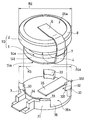
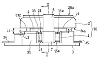
- FIG. 1 is an exploded perspective view conceptually showing an assembled battery structure according to a first embodiment of the present invention. It is the side view which showed notionally the assembled battery structure which concerns on 1st Embodiment.
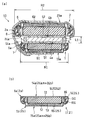
- (A) A cross-sectional view of the assembled battery obtained at the III-III line shown in FIG. 2, and (b) a cross-section of the first flat battery or the second flat battery obtained at the III-III line shown in FIG. FIG.
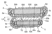
- It is sectional drawing of the assembled battery with which the assembled battery structure which concerns on 3rd Embodiment of this invention is provided.
- An assembled battery structure according to the present invention includes an assembled battery in which a first flat battery and a second flat battery are combined, and a battery holder that holds the assembled battery.
- the first flat battery is a battery accommodated in the battery holder, and the second flat battery is electrically connected to the first flat battery in parallel.
- Each of the first flat battery and the second flat battery has a first surface and a second surface located on opposite sides, and the first surface and the second surface have opposite polarities.
- the battery holder has an engaging portion for holding the first flat battery by being hooked on the first surface of the first flat battery accommodated therein.
- the 2nd surface of the 2nd flat battery is the 1st of the 1st flat battery. It is arranged in a state facing the surface.
- the distance from the first surface of the first flat battery to the second surface of the second flat battery is defined as the first distance, and the same height as the apex of the engaging portion from the first surface of the first flat battery.
- the first distance is the same as the second distance, or the first distance is larger than the second distance.
- the second distance is the apex of the engaging portion with respect to the first surface from the first surface of the first flat battery in the direction perpendicular to the first surface of the first flat battery. The distance to reach the same height.
- the first flat battery is accommodated in the battery holder.
- the second flat battery (the second surface thereof) does not contact the tip of the engaging portion before the engaging portion is applied to the first surface of the first flat battery, so The first flat battery is surely accommodated.
- the first flat battery and the battery holder can be the same size as the conventional flat battery and the battery holder that holds the flat battery. Further, since the first flat battery and the second flat battery are electrically connected in parallel, the assembled battery has a capacity larger than that of the first flat battery.
- the battery capacity is increased by utilizing the space on the first surface of the first flat battery even though the size of the battery holder is the same as the conventional one. It can be made. Therefore, the assembled battery structure enables long-time use in various electronic devices in which flat batteries are used as a power source.
- the first surface of the first flat battery and the second surface of the second flat battery are terminal surfaces having the same polarity, and are formed by the first lead member.
- the first lead member is electrically connected to each other, and the first lead member is electrically connected to the first flat portion electrically connected to the first surface of the first flat battery and the second surface of the second flat battery. And a connected second flat portion.
- the interposition member is provided between the first flat portion and the second flat portion of the first lead member.
- a nickel plate, a nickel-plated stainless steel plate, a stainless nickel clad steel plate, or the like is used for the first lead member.
- the first surface of the first flat battery and the second surface of the second flat battery are electrically connected to the same surface of the first lead member by welding or the like.
- the assembled battery can be manufactured by a simple method such as bending the first lead member. Therefore, it is easy to manufacture the assembled battery, and as a result, work efficiency at the time of manufacture is improved.
- the interposed member has conductivity, and the first surface of the first flat battery and the second surface of the second flat battery have the same polarity. It is a terminal surface and is electrically connected to each other by an interposition member.
- an interposed member for example, a stainless steel plate with nickel plating, a resin plate with nickel plating, or a graphite plate is used.
- the interposition member causes the electrical connection between the first surface of the first flat battery and the second surface of the second flat battery, and the first surface of the first flat battery from the first surface.
- the first distance to the second surface of the two flat battery can be adjusted. Therefore, it is easy to manufacture the assembled battery, and as a result, work efficiency at the time of manufacture is improved.
- the second surface of the first flat battery and the first surface of the second flat battery are electrically connected to each other by the second lead member.
- the second lead member for example, a nickel plate, a nickel-plated stainless steel plate, a stainless nickel clad steel plate, or the like is used.
- an electrical insulating member is interposed between the second lead member and a region having a polarity opposite to the polarity of the second lead member of at least one of the terminal surfaces of the first flat battery and the second flat battery.
- an electric insulating member include an electric insulating tube and an electric insulating tape. According to the electrical insulating member, an electrical short circuit between the positive electrode and the negative electrode is prevented.
- the first surface of the first flat battery and the second surface of the second flat battery are terminal surfaces having opposite polarities, and the first flat battery
- the first surface of the battery is electrically connected to the first surface of the second flat battery by the first lead member
- the second surface of the second flat battery is the first flat by the second lead member.
- the battery is electrically connected to the second surface of the battery.
- the first lead member includes a first flat portion electrically connected to the first surface of the first flat battery, and a second flat portion electrically connected to the first surface of the second flat battery.
- the second lead member includes a first flat part electrically connected to the second surface of the first flat battery, and a second flat part electrically connected to the second surface of the second flat battery.
- the interposition member is provided between the first flat portion of the first lead member and the second flat portion of the second lead member, and has electrical insulation.
- a nickel plate, a nickel-plated stainless steel plate, a stainless nickel clad steel plate, or the like is used for each of the first lead member and the second lead member.
- an electrical insulating member is interposed between the two. Further, between the second lead member and a region having a polarity opposite to the polarity of the second lead member on the terminal surface of at least one of the first flat battery and the second flat battery. In addition, an electrical insulating member is interposed. According to these electrical insulating members, an electrical short circuit between the positive electrode and the negative electrode is prevented.
- the diameter of the second flat battery is preferably larger than the diameter of the first flat battery. As a result, the battery capacity of the assembled battery structure further increases.
- the interposition member has a surface facing the first surface of the first flat battery and a surface facing the second surface of the second flat battery, and is bonded to these surfaces.
- a surface is preferably formed.
- An example of such an interposition member is a double-sided adhesive tape. According to this configuration, the second flat battery is fixed to the first flat battery by the interposition member, whereby an assembled battery is configured.
- a plurality of second flat batteries may be stacked on the first surface of the first flat battery.
- the two second flat batteries adjacent to each other are electrically connected in parallel.
- FIGS. 1 and 2 are an exploded perspective view and a side view, respectively, conceptually showing an assembled battery structure according to a first embodiment of the present invention.
- the assembled battery structure includes an assembled battery 10 in which the first flat battery 1 and the second flat battery 2 are combined, and a battery holder 3 that holds the assembled battery 10. It is configured.
- FIG. 3A is a cross-sectional view of the assembled battery 10 obtained along the line III-III shown in FIG.
- FIG. 3B is a cross-sectional view of the first flat battery 1 or the second flat battery 2 obtained along the line III-III shown in FIG.
- the first flat battery 1 is, for example, a coin-type battery, and includes a positive electrode layer 11, a negative electrode layer 12, a separator 13, a battery case 14, a sealing plate 15, a gasket 16, and an electrolytic solution. (Not shown).
- the battery case 14 and the sealing plate 15 are each formed from a conductive material such as stainless steel, and thus have conductivity.
- the battery case 14 has a bottomed cylindrical shape whose width is larger than the depth, and the opening of the battery case 14 is sealed with a sealing plate 15.
- the sealing plate 15 has an edge portion 151 extending inward of the battery case 14, and the edge portion 151 and the side wall 141 of the battery case 14 have a gasket 16 interposed therebetween. And it is joined by caulking.
- the gasket 16 is an electrically insulating ring-shaped member and fills the gap between the edge 151 and the side wall 141 without any gap.
- the gasket 16 is also interposed between the edge portion 151 and the bottom portion 142 of the battery case 14, and electrically insulates the battery case 14 from the sealing plate 15.
- a synthetic resin such as polypropylene is used as a constituent material of the gasket 16.
- the positive electrode layer 11 and the negative electrode layer 12 are provided in the battery case 14 and face each other, and the separator 13 is interposed between the positive electrode layer 11 and the negative electrode layer 12.
- the positive electrode layer 11 is in contact with the inner surface of the bottom portion 142 of the battery case 14, and the negative electrode layer 12 is in contact with the inner surface of the sealing plate 15. Therefore, the battery case 14 is a positive electrode current collector, and the outer surface of the battery case 14 is the positive electrode terminal surface 1a.
- the sealing plate 15 is a negative electrode current collector, and the outer surface of the sealing plate 15 is a negative electrode terminal surface 1b.
- the positive electrode layer 11 includes a positive electrode active material, a conductive material, and a binder.
- a positive electrode active material for example, fluorinated graphite or metal oxide is used as the positive electrode active material.
- the metal oxide include manganese dioxide and copper oxide.
- the conductive material for example, carbon black such as acetylene black and ketjen black, and graphite such as artificial graphite are used.
- PTFE polytetrafluoroethylene
- PVDF polyvinylidene fluoride
- the negative electrode layer 12 includes, for example, lithium or a lithium alloy.
- the separator 13 for example, an electrically insulating nonwoven fabric or a microporous film is used.
- polyolefin, polyester, or polycarbonate is used as a constituent material of the separator 13.
- the second flat battery 2 has the same configuration as that of the first flat battery 1, and the outer surface of the battery case 24 is a positive electrode terminal surface 2 a and the outer surface of the sealing plate 25 is a negative electrode terminal surface 2 b. (See FIG. 3B).
- the diameter R2 of the second flat battery 2 is larger than the diameter R1 of the first flat battery 1.
- the diameter R ⁇ b> 2 of the second flat battery 2 is substantially the same as the outer diameter R ⁇ b> 3 of the battery holder 3.
- the first flat battery 1 has a diameter R1 of 20.0 mm, a height of 3.2 mm, and a capacity of 220 mAh.
- the second flat battery 2 has a diameter R2 of 24.5 mm, a height of 5.0 mm, and a capacity of 620 mAh.
- the diameter R2 of the second flat battery 2 may be the same as the diameter R1 of the first flat battery 1.
- the diameter R2 of the second flat battery 2 may be larger than the outer diameter R3 of the battery holder 3 or smaller than the outer diameter R3.
- the battery holder 3 is a holder in which the first flat battery 1 is detachably accommodated.
- the battery holder 3 has a side wall 31, an inlet 32 for attaching and detaching the first flat battery 1, and an engaging portion 33.
- the side wall 31 is divided into four parts.
- the engaging portion 33 is formed in each portion of the side wall 31 in the vicinity of the inlet 32, and has a flange portion 331 that protrudes from the inner surface of each portion toward the center of the inlet 32.
- the first flat battery 1 has an outer surface of the bottom 142 of the battery case 14 (hereinafter referred to as “first surface 14 a”, see FIG. 3B). It is accommodated so as to look from the entrance 32 (in FIG. 1, the first surface 14a faces upward).
- first surface 14 a faces upward.
- the first flat battery 1 is accommodated in the battery holder 3 so that the outer surface of the sealing plate 15 is opposite to the first surface 14a.
- a region on the side (a part of the negative electrode terminal surface 1b; hereinafter referred to as “second surface 15a”, see FIG. 3B) faces the inner bottom surface 36a of the battery holder 3.
- the engaging portion 33 (mainly the flange portion 331) is hooked on the first surface 14a of the first flat battery 1, whereby the first flat battery 1 is held by the battery holder 3 and from the battery holder 3.
- the first flat battery 1 is prevented from falling off.
- the battery holder 3 further has a positive electrode terminal 34 and a negative electrode terminal 35.
- the positive electrode terminal 34 is formed on the inner surface of the side wall 31 so as to be in electrical contact with the side wall 141 (part of the positive electrode terminal surface 1a) of the battery case 14 when the first flat battery 1 is accommodated in the battery holder 3. It is provided along.
- the negative electrode terminal 35 is in electrical contact with the second surface 15a (a part of the negative electrode terminal surface 1b) of the first flat battery 1 when the first flat battery 1 is accommodated in the battery holder 3. Is provided.
- the second flat battery 2 is disposed on the first surface 14a of the first flat battery 1 as shown in FIG.
- the second flat battery 2 has an outer surface of the bottom portion 242 of the battery case 24 (a part of the positive electrode terminal surface 2a; hereinafter referred to as “second surface 24a”, see FIG. 3B).
- the first flat battery 1 is disposed so as to face the first surface 14a.
- the 1st surface 14a of the 1st flat battery 1 and the 2nd surface 24a of the 2nd flat battery 2 which mutually oppose are on the terminal surface with the same polarity (positive electrode). It has become.
- the second flat battery 2 is electrically connected to the first flat battery 1 in parallel.
- the first surface 14 a of the first flat battery 1 and the second surface 24 a of the second flat battery 2 having the same polarity (positive electrode) are electrically connected to each other by the first lead member 5.
- first surface 25a Part of the surface 2b, hereinafter referred to as “first surface 25a” (see FIG. 3B), is electrically connected to each other by the second lead member 6 (negative electrode).
- the first lead member 5 (positive electrode) is a U-shaped curved plate-like member, and a first flat portion 51 electrically connected to the first surface 14a of the first flat battery 1 by welding or the like, A second flat portion 52 electrically connected to the second surface 24a of the second flat battery 2 by welding or the like.
- the second lead member 6 (negative electrode) is a plate-like member that is curved in a U shape along the outer peripheral surface of the assembled battery 10, and is electrically connected to the second surface 15a of the first flat battery 1 by welding or the like. And a second flat part 62 electrically connected to the first surface 25a of the second flat battery 2 by welding or the like.
- first lead member 5 and the second lead member 6 are used for each of the first lead member 5 and the second lead member 6.
- first lead member 5 and the second lead member 6 is not limited to a plate-like member, and may be, for example, a linear member.
- the electrical insulating member 7 is electrically insulated so that the positive electrode terminal surface 1a of the first flat battery 1 and the second lead member 6 having the opposite polarity (negative electrode) are electrically insulated. It is interposed between the positive electrode terminal surface 1 a and the second lead member 6.
- the electrical insulating member 7 is an electrical insulating tape and covers a part of the second lead member 6 (mainly a portion in the vicinity of the first flat battery 1).
- the electrical insulation member 8 is electrically insulated so that the positive electrode terminal surface 2a of the second flat battery 2 and the second lead member 6 having the opposite polarity (negative electrode) are electrically insulated. It is interposed between the positive electrode terminal surface 2 a and the second lead member 6.
- the electrical insulating member 8 is an electrical insulating tube and covers a part (mainly the side surface) of the outer peripheral surface of the second flat battery 2. According to the electrical insulating members 7 and 8, in the assembled battery 10, an electrical short circuit between the positive electrode and the negative electrode is prevented.
- Each of the electric insulating members 7 and 8 is not limited to an electric insulating tape or an electric insulating tube, and various types of electric insulating members may be used.
- the interposition member 4 is provided between the first flat part 51 and the second flat part 52 of the first lead member 5.
- the interposition member 4 has a surface 4a facing the first surface 14a of the first flat battery 1 and a surface 4b facing the second surface 24a of the second flat battery 2, and these surfaces 4a and 4b.
- an interposition member 4 for example, a double-sided adhesive tape is used. These bonding surfaces are bonded to the first flat portion 51 and the second flat portion 52 of the first lead member 5, respectively. Accordingly, the second flat battery 2 is fixed to the first flat battery 1 via the interposition member 4.
- the interposition member 4 has a predetermined thickness T.
- the distance from the first surface 14a of the first flat battery 1 to the second surface 24a of the second flat battery 2 is defined as a first distance L1.
- the distance to reach the height is defined as a second distance L2.
- the thickness T of the interposed member 4 is set so that the first distance L1 is larger than the second distance L2.
- the thickness T of the interposition member 4 may be set so that the first distance L1 is the same as the second distance L2.
- the thickness of the first lead member 5 is, for example, 0.05 to 0.15 mm
- the thickness T of the interposed member 4 is, for example, 1.0 to 3.5 mm.
- the interposition member 4 is a double-sided adhesive tape having a square of 10 mm ⁇ 10 mm and a thickness of 2 mm.
- the diameter R2 of the second flat battery 2 is larger than the diameter R1 of the first flat battery 1. Even in such a case, according to the assembled battery structure of the first embodiment, when the first flat battery 1 is accommodated in the battery holder 3, the first flat battery 1 is engaged with the first surface 14a.
- the second flat battery 2 (the second surface 24a thereof) does not come into contact with the tip of the engaging portion 33 before the joining portion 33 is engaged, so that the first flat battery 1 is securely attached to the battery holder 3. Will be housed. Therefore, the 1st flat type battery 1 and the battery holder 3 can use the same size as the conventional flat type battery and the battery holder holding it.
- the assembled battery 10 has a larger capacity than the first flat battery 1. Therefore, according to the assembled battery structure of the first embodiment, the space on the first surface 14a of the first flat battery 1 is used even though the size of the battery holder 3 is the same as the conventional one. As a result, the battery capacity can be increased. Therefore, the assembled battery structure according to the first embodiment can be used for a long time in various electronic devices in which a flat battery is used as a power source. In addition, design changes relating to the printed circuit board are unnecessary in various electronic devices.
- the battery capacity is up to 840 mAh.
- the first flat battery 1 when the first flat battery 1 has a capacity of 220 mAh and the second flat battery 2 has a capacity of 620 mAh, according to the assembled battery structure of the first embodiment, the battery capacity is up to 840 mAh. Can be increased.
- the first flat battery 1 when used alone as a power source, it was difficult to output a pulse current larger than 100 mA.
- the battery capacity increases to 840 mAh, a pulse current of about 700 mA is generated. It becomes possible to output. Thus, it becomes possible to cope with various output forms by increasing the battery capacity.
- the assembled battery structure of the first embodiment conventional battery holders mounted on various electronic devices can be used as the battery holder 3 constituting the structure. Therefore, it is not necessary to replace the battery holder, and therefore the influence of heat (for example, failure or damage of the electronic component) that can be caused by replacing the battery holder is avoided.
- the 1st surface 14a and the 2nd flat type of the 1st flat battery 1 are compared with the same surface of the flat 1st lead member 5 in the manufacture process.
- the assembled battery 10 can be manufactured by a simple method in which the first lead member 5 is bent after the second surface 24a of the battery 2 is electrically connected by welding or the like. Therefore, the assembled battery 10 can be easily manufactured, and as a result, the work efficiency at the time of manufacturing is improved.
- FIG. 4 is a cross-sectional view of an assembled battery 20 provided in an assembled battery structure according to a second embodiment of the present invention.
- the structure different from 1st Embodiment among the assembled battery structures of 2nd Embodiment is demonstrated.
- the first surface 14a of the first flat battery 1 and the second surface 24a of the second flat battery 2 are the first leads as in the first embodiment. Instead of being electrically connected to each other by the member 5, they are electrically connected to each other by an interposing member 41 having conductivity.
- the interposition member 41 is, for example, a cylindrical or disk-shaped conductor, and as the constituent material of the interposition member 41, for example, a nickel-plated stainless steel plate, a nickel-plated resin plate, or a graphite plate is used. It is done.
- the interposed member 41 is a cylindrical conductor having a diameter of 14 mm.
- the interposition member 41 has a surface 41a facing the first surface 14a of the first flat battery 1 and a surface 41b facing the second surface 24a of the second flat battery 2, On the surfaces 41a and 41b, an adhesive surface is formed by applying a conductive adhesive.
- a conductive adhesive for example, a conductive paste containing a conductive filler and a binder is used.
- silver powder is used for the conductive filler, and for example, an epoxy resin is used for the binder.
- the interposition member 41 has a predetermined thickness T1.
- the thickness T1 of the interposing member 41 is set such that the first distance L1 from the first surface 14a of the first flat battery 1 to the second surface 24a of the second flat battery 2 is the second distance L2 (FIG. 2). It is set to be larger than (see).
- the thickness T1 of the interposition member 41 may be set so that the first distance L1 is the same as the second distance L2.
- the thickness T1 of the interposition member 41 is, for example, 1.0 to 3.5 mm.
- the size of the battery holder 3 is the same as that of the conventional one, but on the first surface 14a of the first flat battery 1.
- the battery capacity can be increased by utilizing this space. Therefore, the assembled battery structure according to the second embodiment enables long-term use in various electronic devices in which flat batteries are used as a power source.
- the electrical connection of the 1st surface 14a of the 1st flat battery 1 and the 2nd surface 24a of the 2nd flat battery 2 is carried out by the interposition member 41.
- the first distance L1 from the first surface 14a of the first flat battery 1 to the second surface 24a of the second flat battery 2 can be adjusted. Therefore, the assembled battery 20 can be easily manufactured, and as a result, the work efficiency at the time of manufacturing is improved.
- FIG. 5 is a cross-sectional view of an assembled battery 30 provided in an assembled battery structure according to a third embodiment of the present invention.
- the structure different from 1st Embodiment among the assembled battery structures of 3rd Embodiment is demonstrated.
- the outer surface of the bottom 242 of the battery case 24 (part of the positive electrode terminal surface 2 a) is the first surface 24 b
- the first surface of the outer surface of the sealing plate 25 is the first surface.
- a region opposite to 24b (a part of the negative electrode terminal surface 2b) serves as the second surface 25b (see FIG. 3B).
- the second flat battery 2 is arranged with the second surface 25 b facing the first surface 14 a (part of the positive electrode terminal surface 1 a) of the first flat battery 1.
- the 1st surface 14a of the 1st flat battery 1 and the 2nd surface 25b of the 2nd flat battery 2 which mutually oppose become a terminal surface with a reverse polarity. Yes.
- the second flat battery 2 is electrically connected to the first flat battery 1 in parallel as follows. That is, the first surface 14 a of the first flat battery 1 and the first surface 24 b of the second flat battery 2 having the same polarity (positive electrode) are electrically connected to each other by the first lead member 53. Further, the second surface 15 a of the first flat battery 1 and the second surface 25 b of the second flat battery 2 having the same polarity (negative electrode) are electrically connected to each other by the second lead member 63.
- the first lead member 53 (positive electrode) is a plate-like member curved in a U shape along the outer peripheral surface of the second flat battery 2, and is electrically connected to the first surface 14 a of the first flat battery 1 by welding or the like.
- the second lead member 63 (negative electrode) is a plate-like member that is curved in a U shape along the outer peripheral surface of the first flat battery 1, and is welded to the second surface 15 a of the first flat battery 1.
- Each of the first lead member 53 and the second lead member 63 is made of, for example, a nickel plate, a nickel-plated stainless steel plate, a stainless nickel clad steel plate, or the like.
- Each of the first lead member 53 and the second lead member 63 is not limited to a plate-like member, and may be a linear member, for example.
- the electrical insulation member 71 is electrically insulated so that the negative electrode terminal surface 2b of the second flat battery 2 and the first lead member 53 having the opposite polarity (positive electrode) are electrically insulated. It is interposed between the negative electrode terminal surface 2 b and the first lead member 53.
- the electric insulating member 71 is an electric insulating tube and covers a part of the outer peripheral surface of the second flat battery 2 (mainly the side surface and the edge of the second surface 25b). The electrical insulating member 71 also prevents an electrical short circuit between the positive electrode terminal surface 2a of the second flat battery 2 and the second lead member 63 having the opposite polarity (negative electrode). ing.
- the electrical insulation member 81 is electrically insulated so that the positive electrode terminal surface 1a of the first flat battery 1 and the second lead member 63 having the opposite polarity (negative electrode) are electrically insulated. It is interposed between the positive electrode terminal surface 1 a and the second lead member 63.
- the electrical insulating member 81 is an electrical insulating tape and covers a part of the second lead member 63 (mainly the portion in the vicinity of the first flat battery 1).
- each of the electric insulating members 71 and 81 is not limited to the electric insulating tape and the electric insulating tube, and various types of electric insulating members may be used.
- an electrically insulating interposition member 42 is provided between the first flat portion 531 of the first lead member 53 and the second flat portion 632 of the second lead member 63.
- the interposition member 42 has a surface 42a facing the first surface 14a of the first flat battery 1 and a surface 42b facing the second surface 25b of the second flat battery 2, and these surfaces 42a and 42b.
- an interposition member 42 for example, a double-sided adhesive tape is used. These bonding surfaces are bonded to the first flat portion 531 of the first lead member 53 and the second flat portion 632 of the second lead member 63, respectively.
- the second flat battery 2 is fixed to the first flat battery 1 via the interposition member 42.
- the interposition member 42 electrically insulates the first flat portion 531 (positive electrode) of the first lead member 53 and the second flat portion 632 (negative electrode) of the second lead member 63.
- the interposition member 42 has a predetermined thickness T2.
- the thickness T2 of the interposition member 42 is set such that the first distance L3 from the first surface 14a of the first flat battery 1 to the second surface 25b of the second flat battery 2 is the second distance L2 (FIG. 2). It is set to be larger than (see).
- the thickness T2 of the interposed member 42 may be set so that the first distance L3 is the same as the second distance L2.
- the thickness of each of the first lead member 53 and the second lead member 63 is, for example, 0.05 to 0.15 mm, and the thickness T2 of the interposed member 42 is, for example, 1.0 to 3.5 mm.
- the interposition member 42 is a double-sided adhesive tape having a square of 10 mm ⁇ 10 mm and a thickness of 2 mm.
- the size of the battery holder 3 is the same as that of the conventional one, but on the first surface 14a of the first flat battery 1.
- the battery capacity can be increased by utilizing this space. Therefore, the assembled battery structure according to the third embodiment enables long-time use in various electronic devices in which flat batteries are used as a power source.
- each part structure of this invention is not restricted to the said embodiment, A various deformation
- a plurality of second flat batteries 2 may be stacked on the first surface 14 a of the first flat battery 1.
- the two second flat batteries 2 adjacent to each other are electrically connected in parallel.
- the battery capacity of the assembled battery structure can be further increased.
- the connection method between the first flat battery 1 and the second flat battery 2 described in the first to third embodiments is appropriately used. Can be adopted.
- an electrical insulation member such as an electrical insulation tube or an electrical insulation tape where necessary.
- the assembled battery structure according to the present invention can be used as a main power source or a backup power source in various electronic devices such as OA (Office Automation) devices, FA (Factory Automation) devices, various meters, and measuring devices.
- OA Office Automation
- FA ctory Automation
Landscapes
- Chemical & Material Sciences (AREA)
- Chemical Kinetics & Catalysis (AREA)
- Electrochemistry (AREA)
- General Chemical & Material Sciences (AREA)
- Engineering & Computer Science (AREA)
- Manufacturing & Machinery (AREA)
- Battery Mounting, Suspending (AREA)
- Connection Of Batteries Or Terminals (AREA)
Abstract
La présente invention concerne une structure de bloc-batterie permettant une utilisation sur le long terme d'une batterie plate dans divers types de dispositifs électroniques. Une première batterie plate (1) et une seconde batterie plate (2) sont connectées électriquement en parallèle dans la structure de bloc-batterie. Un porte-batterie (3) comporte un crochet (33) qui accroche une première surface (14a) de la première batterie plate (1), lorsqu'elle est logée dans le porte-batterie (3), afin de retenir de ce fait la première batterie plate (1). Une seconde batterie plate (2) est agencée au-dessus de la première surface (14a) de la première batterie plate (1) logée dans le porte-batterie (3) via un élément intervenant (4) avec une seconde surface (24a) de la seconde batterie plate (2) faisant face à la première surface (14a) de la première batterie plate (1). Une première distance (L1) entre la première surface (14a) de la première batterie plate (1) et la seconde surface (24a) de la seconde batterie plate (2) est supérieure ou égale à une seconde distance (L2) entre la première surface (14a) de la première batterie plate (1) et la même hauteur que le dessus du crochet (33).
Applications Claiming Priority (2)
| Application Number | Priority Date | Filing Date | Title |
|---|---|---|---|
| JP2013-076367 | 2013-04-01 | ||
| JP2013076367A JP2016115395A (ja) | 2013-04-01 | 2013-04-01 | 組電池構造体 |
Publications (1)
| Publication Number | Publication Date |
|---|---|
| WO2014162694A1 true WO2014162694A1 (fr) | 2014-10-09 |
Family
ID=51658008
Family Applications (1)
| Application Number | Title | Priority Date | Filing Date |
|---|---|---|---|
| PCT/JP2014/001742 Ceased WO2014162694A1 (fr) | 2013-04-01 | 2014-03-26 | Structure de bloc-batterie |
Country Status (2)
| Country | Link |
|---|---|
| JP (1) | JP2016115395A (fr) |
| WO (1) | WO2014162694A1 (fr) |
Families Citing this family (1)
| Publication number | Priority date | Publication date | Assignee | Title |
|---|---|---|---|---|
| KR102939187B1 (ko) * | 2020-02-27 | 2026-03-13 | 현대자동차주식회사 | 충방전 기능을 갖는 차체 부재 |
Citations (5)
| Publication number | Priority date | Publication date | Assignee | Title |
|---|---|---|---|---|
| JPS6395229U (fr) * | 1986-12-10 | 1988-06-20 | ||
| JPH02143772U (fr) * | 1989-05-09 | 1990-12-06 | ||
| JPH0487165U (fr) * | 1990-12-05 | 1992-07-29 | ||
| JPH0722012A (ja) * | 1993-06-29 | 1995-01-24 | Naldec Kk | 電源装置 |
| JPH07114910A (ja) * | 1993-10-20 | 1995-05-02 | Saakit Design:Kk | ボタン形電池の収納構造 |
-
2013
- 2013-04-01 JP JP2013076367A patent/JP2016115395A/ja active Pending
-
2014
- 2014-03-26 WO PCT/JP2014/001742 patent/WO2014162694A1/fr not_active Ceased
Patent Citations (5)
| Publication number | Priority date | Publication date | Assignee | Title |
|---|---|---|---|---|
| JPS6395229U (fr) * | 1986-12-10 | 1988-06-20 | ||
| JPH02143772U (fr) * | 1989-05-09 | 1990-12-06 | ||
| JPH0487165U (fr) * | 1990-12-05 | 1992-07-29 | ||
| JPH0722012A (ja) * | 1993-06-29 | 1995-01-24 | Naldec Kk | 電源装置 |
| JPH07114910A (ja) * | 1993-10-20 | 1995-05-02 | Saakit Design:Kk | ボタン形電池の収納構造 |
Also Published As
| Publication number | Publication date |
|---|---|
| JP2016115395A (ja) | 2016-06-23 |
Similar Documents
| Publication | Publication Date | Title |
|---|---|---|
| JP5208976B2 (ja) | 電池モジュール | |
| JP5442793B2 (ja) | 端子付電気化学セル | |
| JP6108221B2 (ja) | 蓄電素子 | |
| JP5231089B2 (ja) | 密閉型二次電池 | |
| JP2005093239A (ja) | 電池 | |
| JP5651536B2 (ja) | 円筒形二次電池 | |
| JP2008294001A5 (fr) | ||
| JPH0935701A (ja) | 電 池 | |
| CN105849840B (zh) | 电容器 | |
| JP2011216402A (ja) | 角形二次電池 | |
| JP2013118115A (ja) | 組電池の電極集電部構造及び該電極集電部構造を有する組電池 | |
| JP2016091659A (ja) | 蓄電装置、及び蓄電装置の製造方法 | |
| JP6237033B2 (ja) | 蓄電素子及び蓄電モジュール | |
| JP2018160398A (ja) | 蓄電素子の製造方法及び蓄電素子 | |
| WO2016104009A1 (fr) | Élément ctp fixé à l'extérieur, et batterie cylindrique | |
| JP5552634B2 (ja) | 電池接続用具およびそれを用いた組電池モジュール | |
| KR20140106391A (ko) | 비수 전해질 이차 전지 | |
| JP2018056091A (ja) | 円筒形二次電池 | |
| JP2017059346A (ja) | 二次電池および組電池 | |
| JP2016115395A (ja) | 組電池構造体 | |
| JP2016091660A (ja) | 蓄電装置、及び蓄電装置の製造方法 | |
| JP2013239322A (ja) | 電池パックの製造方法および電池パック | |
| JP2015035303A (ja) | 端子構造 | |
| JP2014175191A (ja) | 回路基板へのリード板取り付け方法及びパック電池の製造方法 | |
| KR101310441B1 (ko) | 전기화학 커패시터 |
Legal Events
| Date | Code | Title | Description |
|---|---|---|---|
| 121 | Ep: the epo has been informed by wipo that ep was designated in this application |
Ref document number: 14778484 Country of ref document: EP Kind code of ref document: A1 |
|
| NENP | Non-entry into the national phase |
Ref country code: DE |
|
| 122 | Ep: pct application non-entry in european phase |
Ref document number: 14778484 Country of ref document: EP Kind code of ref document: A1 |
|
| NENP | Non-entry into the national phase |
Ref country code: JP |