WO2014162762A1 - 情報処理装置、情報処理方法、及びプログラム - Google Patents
情報処理装置、情報処理方法、及びプログラム Download PDFInfo
- Publication number
- WO2014162762A1 WO2014162762A1 PCT/JP2014/051536 JP2014051536W WO2014162762A1 WO 2014162762 A1 WO2014162762 A1 WO 2014162762A1 JP 2014051536 W JP2014051536 W JP 2014051536W WO 2014162762 A1 WO2014162762 A1 WO 2014162762A1
- Authority
- WO
- WIPO (PCT)
- Prior art keywords
- hand
- operator
- display
- information processing
- display screen
- Prior art date
- Legal status (The legal status is an assumption and is not a legal conclusion. Google has not performed a legal analysis and makes no representation as to the accuracy of the status listed.)
- Ceased
Links
Images



Classifications
-
- G—PHYSICS
- G06—COMPUTING OR CALCULATING; COUNTING
- G06F—ELECTRIC DIGITAL DATA PROCESSING
- G06F3/00—Input arrangements for transferring data to be processed into a form capable of being handled by the computer; Output arrangements for transferring data from processing unit to output unit, e.g. interface arrangements
- G06F3/01—Input arrangements or combined input and output arrangements for interaction between user and computer
- G06F3/017—Gesture based interaction, e.g. based on a set of recognized hand gestures
-
- G—PHYSICS
- G06—COMPUTING OR CALCULATING; COUNTING
- G06F—ELECTRIC DIGITAL DATA PROCESSING
- G06F1/00—Details not covered by groups G06F3/00 - G06F13/00 and G06F21/00
- G06F1/16—Constructional details or arrangements
- G06F1/1613—Constructional details or arrangements for portable computers
- G06F1/163—Wearable computers, e.g. on a belt
-
- G—PHYSICS
- G06—COMPUTING OR CALCULATING; COUNTING
- G06F—ELECTRIC DIGITAL DATA PROCESSING
- G06F3/00—Input arrangements for transferring data to be processed into a form capable of being handled by the computer; Output arrangements for transferring data from processing unit to output unit, e.g. interface arrangements
- G06F3/01—Input arrangements or combined input and output arrangements for interaction between user and computer
-
- G—PHYSICS
- G06—COMPUTING OR CALCULATING; COUNTING
- G06F—ELECTRIC DIGITAL DATA PROCESSING
- G06F3/00—Input arrangements for transferring data to be processed into a form capable of being handled by the computer; Output arrangements for transferring data from processing unit to output unit, e.g. interface arrangements
- G06F3/01—Input arrangements or combined input and output arrangements for interaction between user and computer
- G06F3/011—Arrangements for interaction with the human body, e.g. for user immersion in virtual reality
-
- G—PHYSICS
- G06—COMPUTING OR CALCULATING; COUNTING
- G06F—ELECTRIC DIGITAL DATA PROCESSING
- G06F3/00—Input arrangements for transferring data to be processed into a form capable of being handled by the computer; Output arrangements for transferring data from processing unit to output unit, e.g. interface arrangements
- G06F3/01—Input arrangements or combined input and output arrangements for interaction between user and computer
- G06F3/03—Arrangements for converting the position or the displacement of a member into a coded form
- G06F3/0304—Detection arrangements using opto-electronic means
-
- G—PHYSICS
- G06—COMPUTING OR CALCULATING; COUNTING
- G06F—ELECTRIC DIGITAL DATA PROCESSING
- G06F3/00—Input arrangements for transferring data to be processed into a form capable of being handled by the computer; Output arrangements for transferring data from processing unit to output unit, e.g. interface arrangements
- G06F3/01—Input arrangements or combined input and output arrangements for interaction between user and computer
- G06F3/048—Interaction techniques based on graphical user interfaces [GUI]
- G06F3/0481—Interaction techniques based on graphical user interfaces [GUI] based on specific properties of the displayed interaction object or a metaphor-based environment, e.g. interaction with desktop elements like windows or icons, or assisted by a cursor's changing behaviour or appearance
- G06F3/04812—Interaction techniques based on cursor appearance or behaviour, e.g. being affected by the presence of displayed objects
-
- G—PHYSICS
- G06—COMPUTING OR CALCULATING; COUNTING
- G06V—IMAGE OR VIDEO RECOGNITION OR UNDERSTANDING
- G06V40/00—Recognition of biometric, human-related or animal-related patterns in image or video data
- G06V40/20—Movements or behaviour, e.g. gesture recognition
- G06V40/28—Recognition of hand or arm movements, e.g. recognition of deaf sign language
Definitions
- the present disclosure relates to an information processing apparatus, an information processing method, and a program.
- GUI Graphic User Interface
- an information processing apparatus such as a PC (Personal Computer).
- a user moves a pointer on a display screen using, for example, a pointing device, and selects an object such as an icon or a button on the display screen, thereby causing a computer to execute a process corresponding to the selected object.
- a pointer on a display screen using, for example, a pointing device, and selects an object such as an icon or a button on the display screen, thereby causing a computer to execute a process corresponding to the selected object.
- Patent Document 1 discloses a technique for determining an operation content of an operator on a display screen by recognizing a gesture operation with both hands of the operator.
- the physical burden on the operator when operating the display screen is large.
- the operator can perform the gesture operation only by the position of the virtual operation surface that is initially set in the real space, and the position of the virtual operation surface cannot be moved. .
- the position and angle of the arm for the gesture operation are restricted, and when the operator performs the operation for a long time, for example, the physical load such as fatigue of the arm is large.
- the present disclosure proposes a new and improved information processing apparatus, information processing method, and program capable of reducing the physical burden on the operator when operating the display screen.
- a hand shape recognition unit that recognizes the hand shape of the operator based on measured information on the hand of the operator, and the hand shape of the operator
- An information processing apparatus includes a display control unit that moves the display position of the operation object on the display screen in accordance with a change in the position of the operator's hand when is a predetermined shape.
- the operator's hand shape is recognized based on the measured information on the operator's hand, and the operator's hand shape Is moved to the display position of the operation object on the display screen in accordance with a change in the position of the operator's hand.
- a computer recognizes a hand shape of the operator based on information about the measured operator's hand, and When the operator's hand shape is a predetermined shape, a program for functioning as a display control unit that moves the display position of the operation object on the display screen according to a change in the position of the operator's hand is provided. Provided.
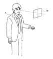
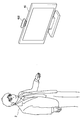
- FIG. 3 is an external view showing a person operating a UI panel according to the first embodiment of the present disclosure.
- FIG. It is explanatory drawing which showed the hardware constitutions of HMD by the embodiment. It is explanatory drawing which showed the example of a display of the display screen by the embodiment. It is the functional block diagram which showed the structure of HMD by the embodiment. It is the 1st explanatory view showing the example of the hand shape which has UI panel by the embodiment. It is the 2nd explanatory view showing the example of the hand shape with UI panel by the embodiment.
- FIG. 6 is an explanatory diagram illustrating an example of an operation for displaying a UI panel according to the embodiment. It is explanatory drawing which showed the example of the hand shape of the pointing by the same embodiment.
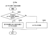
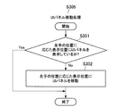
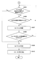
- FIG. 6 is a first flowchart showing in detail a UI panel display / non-display process according to the embodiment; 6 is a second flowchart showing in detail a UI panel display / non-display process according to the embodiment; 5 is a flowchart illustrating in detail a UI panel movement process according to the embodiment.
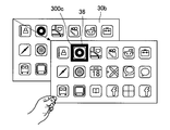
- 14 is an explanatory diagram illustrating a display example of a UI panel and a focus frame according to a second embodiment of the present disclosure.
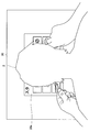
- FIG. 2 is an external view showing a person who operates a UI panel according to the embodiment.
- FIG. 14 is an external view showing a person who operates a UI panel according to a third embodiment of the present disclosure.
- FIG. FIG. 2 is a functional block diagram illustrating a configuration of a video device according to the embodiment. It is the 1st explanatory view showing the example of a display of a display screen by the embodiment. It is the 2nd explanatory view showing the example of a display of a display screen by the embodiment.
- a plurality of constituent elements having substantially the same functional configuration may be distinguished by adding different alphabets after the same reference numeral.
- a plurality of configurations having substantially the same functional configuration are distinguished as necessary, such as a UI panel 30a and a UI panel 30b.
- UI panel 30a and UI panel 30b when it is not necessary to particularly distinguish each of a plurality of constituent elements having substantially the same functional configuration, only the same reference numerals are given.
- the UI panel 30 when it is not necessary to distinguish between the UI panel 30a and the UI panel 30b, they are simply referred to as the UI panel 30.
- the HMD 10 and the video apparatus 40 according to the present embodiment have been created with the above circumstances taken into consideration.
- the HMD 10 and the video apparatus 40 according to the present embodiment enable the operator to move the operation object to a position where it can be easily operated, so that it is possible to reduce the operator's physical load when operating the display screen. .
- the HMD 10 is a display device for showing the operator 2 a display screen 20 as shown in FIG. 2, for example.
- the HMD 10 may be a head-mounted display attached to the head of the operator 2 or may be a glasses-type computer having a see-through display, for example. Further, the HMD 10 can display a captured still image, a moving image, a two-dimensional object or a three-dimensional object drawn by computer graphics on the display screen 20.
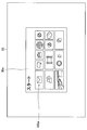
- FIG. 2 is an explanatory diagram showing an example of the display screen 20 displayed by the HMD 10.
- the display screen 20 includes an operation object such as a UI panel 30a (operation surface).
- the HMD 10 can also represent the operation object as a three-dimensional object. For example, when the operator 2 performs an operation of moving the operation object in the depth direction of the display screen 20, the HMD 10 can display the operation object in a reduced size on the display screen 20. Further, the HMD 10 can always display the UI panel 30 in a direction facing the eyes of the operator 2 even if the posture of the operator 2 changes, such as a billboard.
- the UI panel 30a includes an icon 300 for starting various applications, for example.
- the UI panel 30a may further include buttons, images, text, and the like.
- the HMD 10 changes the display position of the UI panel 30 on the display screen 20 by recognizing the hand shape and hand position of the operator 2 based on information acquired by the imaging unit 120 or the sensor unit 122 described later. It is possible to make it.
- the HMD 10 can recognize the operation of the hand of the operator 2 to recognize the selection operation of the icon 2, button, image, text, etc. by the operator 2. It is possible to execute a predetermined process corresponding to the selection operation such as activation of the corresponding application.
- FIG. 1 an example in which the operator 2 operates the UI panel 30 while standing is described.
- the present invention is not limited to this example, and the operator 2 holds the UI panel 30 while sitting in a chair, for example. It is also possible to operate.
- the HMD 10 has a hardware configuration as shown in FIG. 3, for example.
- the HMD 10 includes a CPU (Central Processing Unit) 150, a ROM (Read Only Memory) 152, a RAM (Random Access Memory) 154, an internal bus 156, an interface 158, an input device 160, an output device 162, A storage device 164 and a communication device 166 are provided.
- a CPU Central Processing Unit
- ROM Read Only Memory
- RAM Random Access Memory
- the CPU 150 is comprised as an example of the control part 100 mentioned later, the hand shape recognition part 102, the action recognition part 104, the display control part 106, and the judgment part 108, for example.
- the CPU 150 functions as an arithmetic processing unit and a control unit, and controls overall operations in the HMD 10 according to various programs.
- the CPU 150 may be a microprocessor.
- the ROM 152 stores programs used by the CPU 150, calculation parameters, and the like.
- the RAM 154 temporarily stores programs used in the execution of the CPU 150, parameters that change as appropriate during the execution, and the like.
- the CPU 150, the ROM 152, and the RAM 154 are connected to each other by an internal bus 156 that includes a CPU bus or the like.
- the interface 158 connects the input device 160, the output device 162, the storage device 164, and the communication device 166 to the internal bus 156.
- the input device 160 exchanges data with the CPU 150 and the like via the interface 158 and the internal bus 156.
- the input device 160 receives input of depth information acquired by the sensor unit 122 or a captured image captured by the camera. In addition, the depth information and the captured image whose input has been received by the input device 160 are output to the CPU 150.
- the output device 162 includes, for example, a display device such as a liquid crystal display (LCD) device, an organic light emitting diode (OLED) device, and a lamp. Further, the output device 162 includes an audio output device such as a speaker. For example, the display device displays a captured image or a generated image. On the other hand, the audio output device converts audio data or the like into audio and outputs it.
- a display device such as a liquid crystal display (LCD) device, an organic light emitting diode (OLED) device, and a lamp.
- the output device 162 includes an audio output device such as a speaker.
- the display device displays a captured image or a generated image.
- the audio output device converts audio data or the like into audio and outputs it.
- the storage device 164 is, for example, a data storage device configured as an example of the storage unit 110 described later.
- the storage device 164 may include a storage medium, a recording device that records data on the storage medium, a reading device that reads data from the storage medium, a deletion device that deletes data recorded on the storage medium, and the like.
- the storage device 164 stores programs executed by the CPU 150 and various data.
- the communication device 166 is a communication interface including a communication device for connecting to a communication network such as the Internet.
- the communication device 166 may be a wireless LAN compatible communication device, an LTE (Long Term Evolution) compatible communication device, or a wire communication device that performs wired communication.
- LTE Long Term Evolution
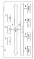
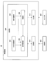
- FIG. 4 is a functional block diagram showing the configuration of the HMD 10 according to the first embodiment.
- the HMD 10 includes a control unit 100, a storage unit 110, and an output unit 112.
- the control unit 100 includes a hand shape recognition unit 102, a motion recognition unit 104, a display control unit 106, and a determination unit 108.
- the control unit 100 has a function of generally controlling the operation of the HMD 10 using hardware such as the CPU 150 and the RAM 154 built in the HMD 10. For example, the control unit 100 controls operations of the storage unit 110 and the output unit 112.
- the hand shape recognition unit 102 is based on, for example, the image of the hand of the operator 2 captured by the imaging unit 120 described later, or the depth information of the hand of the operator 2 measured by the sensor unit 122 described later. Recognize 2 hand shapes.
- the hand shape recognition unit 102 can recognize the hand shape of the operator 2 by performing image pattern matching on the captured image of the hand of the operator 2. For example, a feature amount such as a Haar-like feature amount is extracted in advance by a certain image processing apparatus using captured image data of a plurality of hands having a predetermined shape such as the shape shown in FIG. By performing machine learning, dictionary data for pattern matching can be created. Then, the hand shape recognition unit 102 calculates the distance to the hand of the operator 2 and the feature amount regarding the hand of the operator 2 with respect to the image of the operator 2 captured by the imaging unit 120, and the calculation result By comparing the above dictionary data, it is possible to determine whether or not the hand shape of the operator 2 is the same as the predetermined hand shape.
- the image processing apparatus may be the HMD 10 or a different apparatus.
- the hand shape recognition unit 102 calculates the position of each finger of the hand of the operator 2 based on, for example, bone estimation of the finger based on the depth information of the hand of the operator 2 measured by the sensor unit 122, and It is also possible to recognize the hand shape of the operator 2 from the calculated positional relationship of each finger.
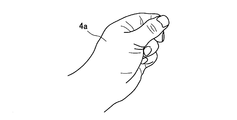
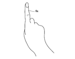
- the hand shape recognition unit 102 recognizes whether or not the hand shape of the first hand of the operator 2 is the hand shape 4a having the UI panel 30 as shown in FIGS. Further, the hand shape recognition unit 102 recognizes whether or not the hand shape of the second hand of the operator 2 is the pointing shape 6a as shown in FIG. As will be described later, the first hand is a hand for moving the display position of the UI panel 30, and the second hand is a hand for performing an operation on the UI panel 30.
- the first hand will be described as the left hand, and the second hand will be described as the right hand.
- the present invention is not limited to this example, and the first hand may be a right hand and the second hand may be a left hand.
- the ease of operation does not change even if the dominant hand of the operator 2 is left or right.
- the HMD 10 has, for example, a left thumb in the real space as shown in FIG. 6. It is possible to arrange the UI panel 30 at a position between the index finger. For this reason, even if the operator 2 moves the left hand, the operator 2 can easily recognize the position of the UI panel 30 in the real space after the movement.
- the HMD 10 determines the position on the UI panel 30 corresponding to the position of the tip of the right index finger in the real space by the operator 2, for example. It can be recognized as a selected position. As an effect of this, the operator 2 can perceive the positional relationship between the position of the left hand in real space, that is, the position where the UI panel 30 is arranged and the position of the finger of the right hand. The desired position can be selected correctly.
- the hand shape recognition unit 102 can also recognize an operation similar to the operation adopted by the operator 2, for example, on the touch panel. For example, when the hand shape recognition unit 102 recognizes an operation of moving the right hand up and down, left and right when the position of the finger of the right hand of the operator 2 is behind the position of the left hand and the right hand is moved, You may recognize that hover operation was performed in the display position corresponding to a position. Further, when the hand shape recognition unit 102 recognizes that the position of the finger of the right hand is ahead of the position of the left hand, a determination operation such as a tap is performed at the display position corresponding to the position of the finger of the right hand. You may recognize that.
- the hand shape recognition unit 102 corresponds to the position of the finger of the right hand when the position of the finger of the right hand is ahead of the position of the left hand and the movement of moving the right hand up, down, left and right is recognized. It may be recognized that a drag operation has been performed at the display position.
- the hand shape recognition unit 102 can also recognize that the left and right hand shapes have been reversed by the operator 2. As this effect, when the operator 2 feels fatigue in one or both hands during the operation, the operator 2 can relieve the fatigue feeling by switching the left and right hand shapes. .
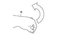
- the motion recognition unit 104 is, for example, an image photographed by the imaging unit 120 or measurement information such as depth information measured by the sensor unit 122 and hand shape learning data stored in advance in the storage unit 110 described later. Based on this, the movement of the hand by the operator 2 is recognized. More specifically, the action recognition unit 104 recognizes an action of rotating the hand forward by the operator 2 (hereinafter also referred to as an action of rotating the hand in the first direction). For example, when the hand shape of the left hand of the operator 2 is the hand shape 4b holding the hand as shown in FIG. 7, the motion recognition unit 104 rotates the rotation amount of the hand shape 4b stored in the storage unit 110. The operation of rotating the hand forward is recognized by calculating the rotation angle of the left hand based on each learning data.
- the action recognition unit 104 recognizes an action of rotating the hand by the operator 2 reversely (hereinafter also referred to as an action of rotating the hand in the second direction).
- the first direction may be a direction in which the left hand is rotated from a state in which the thumb faces downward to a state in which the thumb faces upward.
- the second direction is the opposite direction to the first direction.
- the display control unit 106 moves the display position of the UI panel 30 on the display screen 20 according to a change in the position of the operator 2 hand. For example, when the operator 2 moves the left hand upward while the left hand is in a predetermined shape, the display control unit 106 can also move the UI panel 30 upward in the display screen 20. It is. When the operator 2 moves the left hand forward while the left hand is in a predetermined shape, the display control unit 106 reduces the UI panel 30 to move in the depth direction of the display screen 20. It is also possible to display it.
- the display control unit 106 displays the UI panel 30 in an enlarged manner.
- the predetermined shape may be set to, for example, the hand shape 4a having the UI panel 30, or may be set to another shape.
- the display control unit 106 switches between displaying and not displaying the UI panel 30 on the display screen 20 based on the recognition result of the hand of the operator 2 by the motion recognition unit 104. For example, when the operation recognizing unit 104 recognizes the operation of rotating the hand by the operator 2 forward, the display control unit 106 sets the position on the display screen 20 corresponding to the position of the hand after the operator 2 rotates. It is also possible to display the UI panel 30. Further, when the operation recognizing unit 104 recognizes the operation of rotating the hand reversely by the operation recognizing unit 104 while the UI panel 30 is displayed on the display screen 20, the display control unit 106 displays the UI panel 30. It can also be hidden.
- the display control unit 106 can also change the ratio of the amount of movement of the UI panel 30 on the display screen 20 to the amount of change in the position of the left hand according to the positional relationship between the left hand and the right hand. More specifically, when the left hand is ahead of the right hand, the display control unit 106 reduces the amount of change in the position of the left hand as the distance between the left hand and the right hand in the front-rear direction of the operator 2 is smaller. It is also possible to reduce the rate of movement of the UI panel 30 on the display screen 20.
- the ratio of the amount of movement of the UI panel 30 on the display screen 20 to the amount of change in the position of the left hand is set to 50%
- the UI decreases as the distance between the left hand and the right hand decreases.
- the ratio of the movement amount of the panel 30 may be gradually decreased from 50% ⁇ 40% ⁇ 30%. Further, when the distance between the left hand and the right hand becomes smaller than a predetermined distance, even if the rate of movement of the UI panel 30 is set to 0%, that is, the display position of the UI panel 30 is fixed. Good.
- the HMD 10 can also set in advance the ratio of the movement amount of the UI panel 30 to the change amount of the hand position so that it differs between the left hand and the right hand.
- the ratio of the amount of movement of the UI panel 30 to the amount of change in the position of the hand is greater for the right hand, that is, the hand that selects the UI panel 30 than for the left hand, that is, the hand with the UI panel 30.
- the operator 2 tries to select the icon 300, there is an advantage that the icon 300 can be selected more easily without moving the right hand much.
- the display control unit 106 can also prevent the UI panel 30 from being displayed on the display screen 20 when the hand shape recognition unit 102 does not recognize that the hand shape of the operator 2 is a predetermined shape.
- the display control unit 106 can also superimpose and display, for example, the arm or part of the body of the operator 2 captured by the imaging unit 120 on the display screen 20.
- the determination unit 108 determines the operation content of the operator 2 based on the position of the finger of the right hand. Can be determined. For example, when the hand shape recognition unit 102 recognizes that the finger position of the right hand is ahead of the position of the left hand, the determination unit 108 determines the position on the UI panel 30 corresponding to the finger position of the right hand. It may be determined that the operator 2 has selected.
- the storage unit 110 stores, for example, various kinds of information such as a preset value of the ratio of the movement amount of the UI panel 30 to the change amount of the left and right hand positions, video information on the display screen 20, and the like.
- the output unit 112 displays the display screen 20 according to an instruction from the display control unit 106, for example.
- the imaging unit 120 has a function of imaging an external image on an imaging element such as a CCD (Charge Coupled Device) or a CMOS (Complementary Metal Oxide Semiconductor) through a lens and capturing a still image or a moving image.
- the imaging unit 120 transmits the captured image to the HMD 10.
- the imaging unit 120 can be installed in the HMD 10 so as to be positioned above the face of the operator 2 like the sensor unit 122 illustrated in FIG. 1, for example.
- the sensor unit 122 measures depth information of an external object such as the hand of the operator 2 using, for example, a depth sensor. Further, the sensor unit 122 transmits the measured information to the HMD 10.
- the sensor unit 122 can be installed in the HMD 10 so as to be positioned above the face of the operator 2 as shown in FIG. 1, for example.
- the configuration according to the first embodiment is not limited to the configuration described above.
- the HMD 10 may include any one or more of the imaging unit 120 and the sensor unit 122 inside.
- any one of the imaging unit 120 and the sensor unit 122 may not be installed.
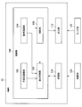
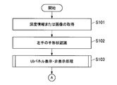
- FIG. 9 is a flowchart showing a part of the operation according to the first embodiment.
- the imaging unit 120 captures an image of the hand of the operator 2 and transmits the captured image to the HMD 10. Further, the sensor unit 122 measures depth information up to the hand of the operator 2 and transmits the measured depth information to the HMD 10 (S101).
- the hand shape recognition unit 102 recognizes the hand shape of the left hand of the operator 2 based on the image taken by the imaging unit 120 or the depth information measured by the sensor unit 122 (S102).
- the HMD 10 performs a “UI panel display / non-display process” to be described later (S103).
- the display control unit 106 checks whether or not the UI panel 30 is being displayed on the display screen 20 (S104). When the UI panel 30 is not displayed (S104: No), the HMD 10 maintains the current operation.
- the HMD 10 detects the pointing operation by the operator 2 (S105). More specifically, the hand shape recognizing unit 102 recognizes whether the hand shape of the right hand of the operator 2 is, for example, a pointing shape, thereby determining whether or not the pointing operation has been performed by the operator 2. to decide.
- the HMD 10 maintains the current operation.
- the HMD 10 increases the multiplier of the camera shake filter of the UI panel 30 (S106). More specifically, the display control unit 106 decreases the ratio of the amount of movement of the UI panel 30 on the display screen 20 to the amount of change in the position of the left hand of the operator 2.
- the hand shape recognition unit 102 recognizes whether or not the position of the finger of the right hand of the operator 2 is ahead of the position of the left hand (S107). When the position of the finger of the right hand is behind the position of the left hand (S107: No), the HMD 10 maintains the current operation.
- the HMD 10 detects the selection position of the pointing operation (S108). More specifically, the determination unit 108 determines that the position on the UI panel 30 corresponding to the position of the finger of the right hand has been selected by the operator 2.
- the HMD 10 can start an application corresponding to the selected icon 300.
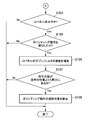
- the hand shape recognition unit 102 recognizes whether or not the hand shape of the left hand of the operator 2 is a hand shape having the UI panel 30 (S201).
- the display control unit 106 displays the UI panel 30 at a position on the display screen 20 corresponding to the position of the left hand of the operator 2. (S202).
- the display control unit 106 hides the UI panel 30 on the display screen 20 (S203).
- the UI panel 30 can be displayed by the operator 2 simply by changing the hand shape of the left hand to the hand shape having the UI panel 30, so that the UI panel 30 can be displayed easily. And the display position of the UI panel 30 can be easily moved.
- the operation recognition unit 104 determines whether or not the operation by the operator 2 to reversely rotate the hand, that is, the operation to rotate the hand in the second direction is performed. Is confirmed (S302).
- the display control unit 106 hides the UI panel 30 on the display screen 20 (S303).
- the hand shape recognition unit 102 indicates that the hand shape of the left hand of the operator 2 is a hand shape having the UI panel 30. It is recognized whether or not (S302).
- the HMD 10 performs a “UI panel movement process” described later (S305).
- the HMD 10 ends the UI panel display / non-display processing.
- the display control unit 106 checks whether or not the UI panel 30 is displayed at a position on the display screen 20 corresponding to the position of the left hand of the operator 2 (S351). When the UI panel 30 is not displayed at the position on the display screen 20 corresponding to the position of the left hand (S351: No), the display control unit 106 displays the UI at the position on the display screen 20 corresponding to the position of the left hand. The panel 30 is moved (S352).
- the operation recognition unit 104 performs an operation of rotating the hand forward by the operator 2, that is, an operation of rotating the hand in the first direction. It is confirmed whether or not (S306).
- the display control unit 106 displays the UI panel at the position on the display screen 20 corresponding to the position of the hand after the operator 2 rotates. 30 is displayed (S307).
- the HMD 10 ends the UI panel display / non-display process.
- the HMD 10 displays the UI panel 30 unless the operator 2 performs a predetermined operation such as an operation of rotating the hand in the reverse direction. Keep doing. For this reason, the operator 2 can continue to display the UI panel 30 even when the hand shape of the left hand is changed or the left hand is retracted, so that the operator 2 holds the UI panel 30 in a more comfortable posture. There is an advantage that it can be operated.
- the operator 2 changes the shape of the left hand to, for example, the pointing shape 6a, so that the operator 2 operates the UI panel 30 with only the left hand, that is, with only one hand. Is also possible.
- the HMD 10 determines which one of the first operation example illustrated in FIG. 11 and the second operation example illustrated in FIG. 12 is to be adopted depending on the type and display content of the UI panel 30. Is also possible. More specifically, the display control unit 106 performs the first operation for an operation object that is assumed to be temporarily displayed, such as when the amount of information included in the UI panel 30 is small or a search window. An example may be adopted. This is because the first operation example is lighter in processing and easier to operate.
- the display control unit 106 performs the second operation for an operation object that is desirably displayed for a long time, such as a route guidance display to a destination, when the amount of information included in the UI panel 30 is large.
- a route guidance display to a destination when the amount of information included in the UI panel 30 is large.
- An example may be adopted. This is because in the second operation example, unless the operator 2 performs a predetermined operation, it is possible to continuously display the operation object.
- the HMD 10 changes the hand shape of the operator 2 based on the measured information about the hand of the operator 2.
- the hand shape of the left hand of the operator 2 is a predetermined shape
- the display position of the UI panel 30 on the display screen 20 is moved according to the change in the position of the left hand of the operator 2.
- the HMD 10 can reduce the physical load on the operator 2.
- the operator 2 can place the UI panel 30 at a position where the pointing operation of the right hand is easy, so that physical pain hardly occurs even if the operation is performed for a long time.
- the HMD 10 moves to the position of the hand after the rotation of the operator 2 when the operation of rotating the hand of the operator 2 is recognized. It is also possible to display the UI panel 30 at a position on the corresponding display screen 20.
- the HMD 10 can also hide the UI panel 30 on the display screen 20 when the operation of reversing the hand of the operator 2 is recognized while the operation object is displayed. . Therefore, when the UI panel 30 is being displayed, the operator 2 can continue to display the UI panel 30 even if the hand shape of the left hand is changed or the left hand is retracted. Can operate the UI panel 30 in a more comfortable posture.
- the HMD 10 can set the ratio of the movement amount of the UI panel 30 to the change amount of the hand position so that the right hand is smaller than the left hand. For this reason, when the operator 2 is going to select the icon 300, he can select the desired icon 300, without moving a right hand largely.
- the HMD 10 when the left hand is ahead of the right hand, the HMD 10 is configured such that the smaller the distance between the left hand and the right hand in the front-rear direction of the operator 2 is, It is also possible to reduce the ratio. For this reason, when the operator 2 performs a pointing operation to select the icon 300, even if the left hand moves against the intention of the operator 2, the HMD 10 may be displaced from the position of the UI panel 30. Can be suppressed. Therefore, the operator 2 can select the icon 300 more easily and correctly.
- the HMD 10 can also display, for example, an arm or a part of the body of the operator 2 that is imaged by the imaging unit 120 so as to be superimposed on the display screen 20. For this reason, since the operator 2 can easily recognize that he / she is operating, the operator 2 can operate intuitively.
- the HMD 10 according to the second embodiment has the same components as the HMD 10 according to the first embodiment shown in FIG. Therefore, here, the description will focus on the differences from the first embodiment.
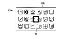
- the display control unit 106 displays the focus frame 36 at a position on the display screen 20 corresponding to the position of the viewpoint of the operator 2. For example, as shown in FIG. 14, the display control unit 106 displays the UI panel 30b and the focus frame 36 separately, and displays the focus frame 36 so as to be positioned in front of the UI panel 30b. Is possible. In addition, as shown in FIG. 15, the display control unit 106 sets the focus frame 36 so as to be positioned in front of the operator's eyes at the same height as the operator's eyes in real space. It is also possible to arrange.
- the focus frame 36 is an object used for selecting an icon, a button, an image, a text, or the like displayed on the display screen 20, for example.
- an example of an operation method of the UI panel 30 according to the second embodiment will be described with reference to FIG.
- the operator 2 can move the display position of the UI panel 30 on the display screen 20 by moving the position of the left hand up, down, left and right.
- the position of the focus frame 36 is fixed on the display screen 20 in principle. Therefore, as shown in FIG. 16, for example, when the operator 2 desires to select the icon 300 c, the operator 2 moves the right side in FIG. 16 so that the icon 300 c enters the focus frame 36.
- the icon 300c can be selected by moving the UI panel 30b in the downward direction.
- the determination unit 108 when the display position of the UI panel 30 is moved, the determination unit 108 according to the second embodiment indicates that the operator 2 has selected an area corresponding to the focus frame 36 in the moved UI panel 30. Judging. For example, in the example illustrated in FIG. 16, after the UI panel 30 is moved so that the icon 300 c enters the focus frame 36, the determination unit 108 determines that the icon 300 c has been selected by the operator 2. .
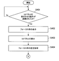
- FIG. 17 is a flowchart showing a part of the operation according to the second embodiment.
- the control unit 100 determines whether or not the display operation of the UI panel 30 has been performed by the operator 2 (S401). For example, as shown in S ⁇ b> 306 in FIG. 12, the operation recognizing unit 104 recognizes whether or not the operation of rotating the left hand forward is performed by the operator 2, whereby the display operation of the UI panel 30 is performed by the operator 2. It may be determined whether or not. Further, as shown in S201 in FIG. 11, the hand shape recognition unit 102 recognizes whether or not the hand shape of the left hand of the operator 2 is a hand shape having the UI panel 30, whereby the display operation of the UI panel 30 is performed. It may be determined whether or not is performed by the operator 2.
- the display control unit 106 moves the focus frame 36 to a position on the display screen 20 according to the position of the viewpoint of the operator 2. It is displayed (S402).
- the display control unit 106 displays the UI panel 30 on the display screen 20 (S403). If the operation recognizing unit 104 recognizes the operation of rotating the left hand of the operator 2 forward in S401, the display control unit 106 displays the position on the display screen 20 corresponding to the position of the left hand after the operator 2 rotates. The UI panel 30 may be displayed at the position.
- the display control unit 106 fixes the display position of the focus frame 36 on the display screen 20 (S404).
- the control unit 100 determines whether or not an operation for deleting the UI panel 30 has been performed by the operator 2 (S405). For example, as shown in S302 in FIG. 12, the operation recognizing unit 104 recognizes whether or not the operator 2 has performed the operation of rotating the left hand in the reverse direction, so that the operator 2 performs the operation of deleting the UI panel 30. It may be determined whether or not it has been received. Further, as shown in S201 in FIG. 11, the hand shape recognition unit 102 recognizes that the hand shape of the left hand of the operator 2 is not a hand shape having the UI panel 30, and thus the operation of deleting the UI panel 30 is performed. It may be determined that the operation is performed by the operator 2.
- the HMD 10 When it is determined that an operation for deleting the UI panel 30 has been performed (S405: Yes), the HMD 10 performs an operation of S409 described later. On the other hand, when it is determined that the operation for deleting the UI panel 30 has not been performed (S405: No), the hand shape recognition unit 102 determines that the hand shape of the left hand of the operator 2 is the hand having the UI panel 30. It is recognized whether or not the position of the left hand has been moved (S406). When the hand shape of the left hand is not a hand shape having the UI panel 30 or when the position of the left hand is not moved (S406: No), the HMD 10 performs the operation of S405 again.
- the HMD 10 moves the display position of the UI panel 30 on the display screen 20. (S407).
- the determination unit 108 determines whether or not an area corresponding to the focus frame 36 on the UI panel 30 has been selected by the operator 2 (S408). For example, the determination unit 108 determines whether or not a predetermined time has passed while the icon 300, the button, and the like are in the focus frame 36, so that the operator 2 selects an area using the focus frame 36. It may be determined whether or not.
- the HMD 10 When it is determined that the area selection by the focus frame 36 has not been made (S408: No), the HMD 10 performs the operation of S405 again. On the other hand, when it is determined that the area selection by the focus frame 36 has been made (S408: Yes), the control unit 100 executes a predetermined process such as starting an application corresponding to the selected icon 300, for example. To do. Then, the display control unit 106 deletes the UI panel 30 on the display screen 20 (S409).
- the display control unit 106 erases the focus frame 36 on the display screen 20 (S410).
- the operation according to the second embodiment is not limited to the above-described operation.
- the display control unit 106 may display the focus frame 36 on the display screen 20 regardless of the display operation of the UI panel 30 by the operator 2.
- the display control unit 106 may always display the focus frame 36, or may display the focus frame 36 when a predetermined operation is performed by the operator 2.
- the determination unit 108 cancels the region selection in S408 by the operator 2. You may judge that. For example, when the motion recognizing unit 104 recognizes an operation of the operator 2 to reversely rotate the left hand, or the hand shape recognizing unit 102 does not recognize that the hand shape of the left hand of the operator 2 is a hand shape having the UI panel 30. When it is recognized, the determination unit 108 may determine that the region selection has been canceled by the operator 2.
- the HMD 10 may repeat the operation of S405 again instead of performing the operations after S409.
- the HMD 10 may repeat the operation of S401 again instead of performing the operation of S410.
- the HMD 10 displays the focus frame 36 at the position on the display screen 20 according to the position of the viewpoint of the operator 2, If the display position of the UI panel 30 is moved, it is determined that the operator 2 has selected an area corresponding to the focus frame 36 in the moved UI panel 30. For this reason, when the operator 2 moves the UI panel 30 by moving the position of the left hand so that the region desired to be selected in the UI panel 30 enters the focus frame 36, the operator 2 You can make a choice. Therefore, the operator 2 can operate the UI panel 30 with only one hand and can easily operate it.
- the HMD 10 displays the display screen 20 and the UI panel 30.
- the video device 40 such as a television receiver displays the display screen 20 and the UI panel 30.
- the video device 40 is a device for displaying the display screen 20 as shown in FIG. 2, for example.
- the video device 40 may be a liquid crystal display device, an OLED device, a plasma display device, or the like, for example.
- the display screen 20 displayed by the video device 40 may be the same as or different from the display screen 20 displayed by the HMD 10 according to the first embodiment.
- the operator 2 is basically located in front of the video device 40 and can operate an operation object such as the UI panel 30 while looking at the display of the video device 40. It is. Similar to the HMD 10, the video device 40 recognizes the hand shape and hand position of the operator 2 based on information acquired by an imaging unit 420 or a sensor unit 422, which will be described later, and thereby the UI panel 30 on the display screen 20. The display position can be changed.
- the video apparatus 40 recognizes the operation of the hand of the operator 2 to recognize the selection operation of the icon 300, button, image, text, etc. by the operator 2, and corresponds to the selected icon 300, for example. It is possible to execute a predetermined process corresponding to the selection operation, such as starting an application to be executed.
- FIG. 19 an example in which the operator 2 operates the UI panel 30 while standing is described.
- the present invention is not limited to this example, and the operator 2 holds the UI panel 30 while sitting in a chair, for example. It is also possible to operate.
- the hardware configuration of the video apparatus 40 may be the same as the hardware configuration of the HMD 10 according to the first embodiment shown in FIG.
- FIG. 20 is a functional block diagram showing the configuration of the video apparatus 40 according to the third embodiment.
- the video device 40 includes a control unit 400, a storage unit 410, and an output unit 412.
- the control unit 400 includes a hand shape recognition unit 402, an operation recognition unit 404, a display control unit 406, and a determination unit 408.
- the function of each component is approximately the same as that of each component in the HMD 10 according to the first embodiment. Therefore, here, the description will focus on the differences from the first embodiment.
- the operator 2 operates the UI panel 30 at a certain distance from the video device 40. For this reason, when the hand of the operator 2 is on the extension line connecting the viewpoint of the operator 2 and the UI panel 30, for example, as shown in FIG. 21, the hand of the operator 2 is shielded on the UI panel 30. An area where the operator 2 cannot be seen may be generated.
- the display control unit 406 operates like the UI panel 30a in FIG. It is possible to display the UI panel 30 in an area different from the area blocked by the hand of the operator 2 on the display screen 20 when viewed from the operator 2.
- the display control unit 406 displays the operator 2 on the display screen 20 as viewed from the operator 2 based on the relative position information of the face and hand of the operator 2 with respect to the video apparatus 40 measured by the sensor unit 422. The area blocked by the hand may be calculated. Then, the display control unit 406 may display the UI panel 30 in an area different from the calculated area.
- the display control unit 406 superimposes the virtual hand image on the position on the display screen 20 corresponding to the position of the hand of the operator 2, such as the left hand image 32 and the right hand image 34 in FIG. It is also possible to display. In general, it is said that about 80% of the information that humans receive from the outside world is visual information, and humans tend to act mainly based on visual information. Therefore, even if the UI panel 30 is displayed as shown in FIG. 22, the operator 2 operates the UI panel 30 while looking at the image of the hand, so that the UI panel 30 can be accurately displayed without deteriorating the operability. 30 can be operated.
- the present invention is not limited to this example.
- the captured image such as the hand or upper body of the operator 2 to be displayed may be superimposed on the display screen 20.
- only one of the images such as the left-hand image 32 may be displayed.
- imaging unit 420 and the sensor unit 422 are substantially the same as those of the imaging unit 120 and the sensor unit 122 according to the first embodiment, respectively.
- the imaging unit 420 and the sensor unit 422 can be installed in the video apparatus 40 so as to be positioned at the upper center in the horizontal direction of the display, for example, like the sensor unit 422 shown in FIG.
- the configuration according to the first embodiment is not limited to the configuration described above.
- the video apparatus 40 may include any one or more of the imaging unit 120 and the sensor unit 122 inside.
- any one of the imaging unit 420 and the sensor unit 422 may not be installed.
- the configuration according to the third embodiment has been described above. Subsequently, an operation according to the third embodiment will be described.
- the video apparatus 40 according to the third embodiment performs, for example, an operation substantially similar to the operation according to the first embodiment shown in FIGS. 9 to 13 or the operation according to the second embodiment shown in FIGS. Is possible. Therefore, the description is omitted here.
- the video apparatus 40 recognizes the hand shape of the operator 2 based on the measured information related to the hand of the operator 2, and the hand shape of the left hand of the operator 2 Is a predetermined shape, the display position of the UI panel 30 on the display screen 20 is moved according to the change in the position of the left hand of the operator 2. For this reason, as in the first embodiment or the second embodiment, the operator 2 can change the position of the UI panel 30 to an easily operable position by moving the left hand. 40 can reduce the physical load of the operator 2.
- the video device 40 is blocked by the hand of the operator 2 on the display screen 20 when viewed from the operator 2.
- the UI panel 30 is displayed in an area different from the area. For this reason, the video device 40 can prevent part of the UI panel 30 from being hidden by the operator 2's hand in the field of view of the operator 2, so that the operator 2 can be positioned to face the display.
- the UI panel 30 can be operated without reducing the visibility.
- the video device 40 is a display device such as a television receiver or a PC display
- the operator 2 displays the display screen 20 displayed on the video device 40 together with other persons such as family members and friends. It is possible to operate the UI panel 30 while watching. Furthermore, the operator 2 can change the operation of the UI panel 30 to another person, and the operation of the UI panel 30 can be shared and enjoyed among a plurality of persons.
- the HMD 10 or the video device 40 can show different images in consideration of parallax to the left eye and the right eye of the operator 2 with respect to the display screen 20 or the UI panel 30.
- the HMD 10 has two displays for the left eye and the right eye, and can show the left eye image and the right eye image to the operator 2.
- the video device 40 may be a display device for 3D display.
- the operator 2 can also see different images with the left eye and the right eye by wearing dedicated glasses and viewing the display screen 20 displayed on the video device 40. According to this modification, the operator 2 can perceive the display screen 20 or the UI panel 30 in a more three-dimensional manner, and thus can operate the UI panel 30 more intuitively.
- the HMD 10 or the video device 40 can cause the operator 2 to change the size of the display screen 20 or the UI panel 30 by selecting a predetermined button on the UI panel 30 or the like.
- the operator 2 can display the display screen 20 or the UI panel 30 in a size that can be easily operated according to, for example, the height or the width of the operation environment, so that convenience is improved. To do.
- a hand shape recognition unit for recognizing the hand shape of the operator based on the measured information about the hand of the operator;
- a display control unit configured to move a display position of an operation object on a display screen in accordance with a change in the position of the operator's hand when the operator's hand shape is a predetermined shape;
- An information processing apparatus comprising: (2) The information processing apparatus according to (1), wherein the predetermined shape is a shape having the operation object.
- the operation object is an operation surface for an operator to operate the display screen.
- the information processing apparatus further includes a motion recognition unit that recognizes a hand motion by the operator, The display control unit switches between display and non-display of the operation object on the display screen based on the recognition result of the operation of the operator's hand by the operation recognition unit.
- the information processing apparatus according to any one of claims.
- the hand movement is an action of rotating the hand, When the operation recognizing operation of rotating the operator's hand in the first direction is recognized by the operation recognizing unit, the display control unit is configured to display the display screen corresponding to the position of the hand after the operator rotates.
- the information processing apparatus according to (4) wherein the operation object is displayed at a position.
- the display control unit is configured to rotate the operator's hand in a second direction that is opposite to the first direction by the motion recognition unit while the operation object is displayed on the display screen.
- the information processing apparatus according to (5) wherein the operation object is hidden on the display screen when is recognized.
- the display control unit moves the display position of the operation object according to a change in the position of the first hand when the hand shape of the operator's first hand is the predetermined shape
- the hand shape recognition unit recognizes that the hand shape of the second hand of the operator is a pointing hand shape
- the information processing apparatus is based on the position of the finger of the second hand.
- the information processing apparatus according to any one of (4) to (7), further including a determination unit that determines an operation content of the operator. (9) If the determination unit recognizes that the finger position of the second hand is ahead of the position of the first hand, the operation corresponding to the finger position of the second hand
- the information processing apparatus according to (8), wherein it is determined that a position on the object is selected by the operator.
- the display control unit When the first hand is in front of the second hand, the display control unit is configured such that a distance between the first hand and the second hand in the front-rear direction of the operator is The information processing apparatus according to (11), wherein the smaller the ratio is, the smaller the ratio of the movement amount of the operation object on the display screen to the change amount of the position of the first hand. (13) The display control unit does not display the operation object on the display screen when the hand shape recognition unit does not recognize that the operator's hand shape is the predetermined shape. The information processing apparatus according to any one of 3). (14) When the operator's hand is positioned in a space between a display that displays the display screen and the operator's eyes, the display control unit is configured to display the operator on the display screen as viewed from the operator.
- the information processing apparatus according to any one of (1) to (13), wherein the operation object is displayed in an area different from an area obstructed by a hand.
- the display control unit displays a focus frame at a position on the display screen according to the position of the operator's viewpoint,
- the information processing apparatus further includes a determination unit configured to determine that an area corresponding to the focus frame on the operation surface after movement is selected by the operator when the display position of the operation surface is moved.
- the information processing apparatus according to (3).
- (16) The information processing apparatus according to any one of (1) to (15), wherein the display control unit displays a hand image at a position on the display screen corresponding to a position of the operator's hand.
- the information related to the operator's hand is a value corresponding to a distance from the display that displays the display screen to the operator's hand, or an image of the operator's hand described in (1) to (16).
- the information processing apparatus according to any one of claims.
- An information processing method comprising: (19) Computer A hand shape recognition unit for recognizing the hand shape of the operator based on the measured information about the hand of the operator; A display control unit that moves the display position of the operation object on the display screen in accordance with a change in the position of the operator's hand when the operator's hand shape is a predetermined shape; Program to function as
- HMD 40 video apparatus 100 control unit 102 hand shape recognition unit 104 motion recognition unit 106 display control unit 108 determination unit 110 storage unit 112 output unit 120 imaging unit 122 sensor unit 150 CPU 152 ROM 154 RAM 156 Internal bus 158 Interface 160 Input device 162 Output device 164 Storage device 166 Communication device 400 Control unit 402 Hand shape recognition unit 404 Operation recognition unit 406 Display control unit 408 Judgment unit 410 Storage unit 412 Output unit 420 Imaging unit 422 Sensor unit
Landscapes
- Engineering & Computer Science (AREA)
- Theoretical Computer Science (AREA)
- General Engineering & Computer Science (AREA)
- Human Computer Interaction (AREA)
- Physics & Mathematics (AREA)
- General Physics & Mathematics (AREA)
- Computer Hardware Design (AREA)
- Health & Medical Sciences (AREA)
- Computer Vision & Pattern Recognition (AREA)
- General Health & Medical Sciences (AREA)
- Psychiatry (AREA)
- Social Psychology (AREA)
- Multimedia (AREA)
- User Interface Of Digital Computer (AREA)
- Image Analysis (AREA)
Abstract
Description
1.第1の実施形態の詳細な説明
2.第2の実施形態の詳細な説明
3.第3の実施形態の詳細な説明
4.変形例
従来、操作者のジェスチャにより機器を操作するアイディアが考えられてきたが、以下の点が課題であった。第1に、従来のアイディアでは、ジェスチャにより機器を操作する場合に物理的なフィードバックが無いので、操作している感覚が操作者に生じない。第2に、従来のアイディアでは、操作者は腕を前方に持ち上げてジェスチャを行う必要があるので、操作者が長時間操作を行う場合には、例えば肩、腕、ひじなどに強い疲労感が生じるなど身体的な苦痛が生じる。第3に、従来のアイディアでは、実空間に配置された仮想のアイコンを2次元ディスプレイ上に表示した場合に、操作者がアイコンを正しく選択することは困難である。
[1-1.基本構成]
最初に、第1の実施形態によるHMD10(情報処理装置)の基本構成について、図1を参照して説明する。図1に示したように、HMD10は、例えば図2に示したような表示画面20を操作者2に見せるための表示装置である。このHMD10は、操作者2の頭部に装着されるヘッドマウントディスプレイであってもよいし、例えばシースルー型のディスプレイを備えたメガネ型コンピュータであってもよい。また、HMD10は、撮影された静止画、動画、またはコンピュータグラフィックスにより描画された2次元オブジェクトや3次元オブジェクトなどを表示画面20に表示することができる。
また、HMD10は、例えば図3に示すようなハードウェア構成を有する。図3に示したように、HMD10は、CPU(Central Processing Unit)150、ROM(Read Only Memory)152、RAM(Random Access Memory)154、内部バス156、インターフェース158、入力装置160、出力装置162、ストレージ装置164、および通信装置166を備える。
(1-2-1.HMD10の構成)
以上、第1の実施形態によるHMD10の基本構成について説明した。続いて、第1の実施形態による構成について詳細に説明する。図4は、第1の実施形態によるHMD10の構成を示した機能ブロック図である。図4に示したように、HMD10は、制御部100、記憶部110、および出力部112を有する。また、制御部100は、手形状認識部102、動作認識部104、表示制御部106、および判断部108を有する。
撮像部120は、外部の映像を、レンズを通して例えばCCD(Charge Coupled Device)やCMOS(Complementary Metal Oxide Semiconductor)などの撮像素子に結像させ、静止画像又は動画像を撮影する機能を有する。また、撮像部120は、撮影した画像をHMD10に送信する。なお、撮像部120は、例えば図1に示したセンサ部122のように、操作者2の顔の上部に位置するようにHMD10に設置されることが可能である。
センサ部122は、例えば深度センサにより操作者2の手などの外部の物体の深度情報を測定する。また、センサ部122は、測定した情報をHMD10に送信する。なお、センサ部122は、例えば図1に示したように、操作者2の顔の上部に位置するようにHMD10に設置されることが可能である。
(1-3-1.全体的な動作)
以上、第1の実施形態による構成について説明した。続いて、第1の実施形態による動作について説明する。図9は、第1の実施形態による動作の一部を示すフローチャートである。
次に、S103におけるUIパネル表示・非表示処理の詳細について説明する。最初に、図11を参照して、UIパネル表示・非表示処理の第1の動作例について説明する。
次に、図12を参照して、UIパネル表示・非表示処理の第2の動作例について説明する。図12に示したように、まず、表示制御部106は、表示画面20にUIパネル30が表示中であるか否かを確認する(S301)。
以上、第1の実施形態による動作について説明したが、上述した動作に限定されない。例えば、S103において、HMD10は、UIパネル30の種類や表示内容によって図11に示した第1の動作例と、図12に示した第2の動作例とのいずれを採用するかを判断することも可能である。より具体的には、表示制御部106は、UIパネル30に含まれる情報量が少ない場合や、検索ウィンドウのような、一時的に表示させることを前提とする操作オブジェクトに関しては、第1の動作例を採用してもよい。この理由は、第1の動作例の方が処理が軽く、かつ、操作がより容易であるためである。また、表示制御部106は、UIパネル30に含まれる情報量が多い場合や、目的地までのルート案内表示のような、長時間表示させておくことが望ましい操作オブジェクトに関しては、第2の動作例を採用してもよい。この理由は、第2の動作例では、操作者2が所定の動作を行わない限り、操作オブジェクトを継続して表示させることが可能であるためである。
以上、例えば図4、図9~図13等を参照して説明したように、第1の実施形態によるHMD10は、測定された操作者2の手に関する情報に基づいて操作者2の手形状を認識し、そして、操作者2の左手の手形状が所定の形状である場合には、表示画面20におけるUIパネル30の表示位置を操作者2の左手の位置の変化に応じて移動させる。このため、操作者2は左手を移動させることによりUIパネル30の位置を操作しやすい位置に変更することができるので、HMD10は操作者2の身体的な負荷を軽減させることができる。例えば、操作者2は右手のポインティング操作が楽な位置にUIパネル30を配置することができるので、長時間操作をしても身体的な苦痛がほとんど生じない。
以上、第1の実施形態について説明した。上述したように、第1の実施形態では、操作者2は、両手を用いてUIパネル30を操作する。次に説明するように、第2の実施形態によれば、操作者2は、片手だけを用いてUIパネル30を操作することができる。
第2の実施形態によるHMD10は、図4に示した第1の実施形態によるHMD10と同様の構成要素を有する。従って、ここでは、第1の実施形態との相違点を中心として説明を行う。
以上、第2の実施形態による構成について説明した。続いて、第2の実施形態による動作について説明する。図17は、第2の実施形態による動作の一部を示すフローチャートである。
なお、第2の実施形態による動作は、上述した動作に限定されない。例えば、表示制御部106は、操作者2によるUIパネル30の表示操作とは無関係にフォーカス枠36を表示画面20に表示させてもよい。例えば、表示制御部106は、フォーカス枠36を常に表示させてもよいし、操作者2により所定の動作がなされた場合にフォーカス枠36を表示させてもよい。
以上、例えば図17~図18等を参照して説明したように、第2の実施形態によるHMD10は、操作者2の視点の位置に応じた表示画面20における位置にフォーカス枠36を表示させ、そして、UIパネル30の表示位置が移動された場合には、移動後のUIパネル30においてフォーカス枠36に対応する領域が操作者2により選択されたことを判断する。このため、操作者2は、UIパネル30において選択を希望する領域がフォーカス枠36の中に入るように、左手の位置を移動させてUIパネル30を移動させた場合には、希望する領域の選択をすることができる。従って、操作者2は、片手だけでUIパネル30を操作することができ、かつ容易に操作することができる。
以上、第2の実施形態について説明した。上述したように、第1の実施形態および第2の実施形態では、HMD10が、表示画面20およびUIパネル30の表示を行う。次に説明するように、第3の実施形態によれば、例えばテレビ受像機のような映像装置40が、表示画面20およびUIパネル30の表示を行う。
まず、第3の実施形態による映像装置40(情報処理装置)の基本構成について図19を参照して説明する。映像装置40は、例えば図2に示したような表示画面20を表示するための装置である。なお、映像装置40は、例えば液晶ディスプレイ装置、OLED装置、プラズマディスプレイ装置などであってもよい。また、映像装置40により表示される表示画面20は、第1の実施形態によるHMD10により表示される表示画面20と同じであってもよいし、異なる画面であってもよい。
(3-2-1.映像装置40)
以上、第3の実施形態による映像装置40の基本構成について説明した。続いて、第3の実施形態による構成について詳細に説明する。図20は、第3の実施形態による映像装置40の構成を示した機能ブロック図である。図20に示したように、映像装置40は、制御部400、記憶部410、および出力部412を有する。また、制御部400は、手形状認識部402、動作認識部404、表示制御部406、および判断部408を有する。なお、各構成要素の機能はそれぞれ、第1の実施形態によるHMD10における各構成要素と概略同様である。従って、ここでは、第1の実施形態との相違点を中心として説明を行う。
撮像部420およびセンサ部422の機能はそれぞれ、第1の実施形態による撮像部120およびセンサ部122と概略同様である。なお、撮像部420およびセンサ部422は、例えば図19に示したセンサ部422のように、ディスプレイの水平方向の中央の上部に位置するように映像装置40に設置されることが可能である。
以上、第3の実施形態による構成について説明した。続いて、第3の実施形態による動作について説明する。第3の実施形態による映像装置40は、例えば図9~図13に示した第1の実施形態による動作、あるいは図17~図18に示した第2の実施形態による動作と概略同様の動作を行うことが可能である。従って、ここでは説明を省略する。
以上説明したように、第3の実施形態による映像装置40は、測定された操作者2の手に関する情報に基づいて操作者2の手形状を認識し、そして、操作者2の左手の手形状が所定の形状である場合には、表示画面20におけるUIパネル30の表示位置を操作者2の左手の位置の変化に応じて移動させる。このため、第1の実施形態または第2の実施形態と同様に、操作者2は左手を移動させることによりUIパネル30の位置を操作しやすい位置に変更することが可能になるので、映像装置40は操作者2の身体的な負荷を軽減させることができる。
なお、添付図面を参照しながら本開示の好適な実施形態について詳細に説明したが、本開示はかかる例に限定されない。本開示の属する技術の分野における通常の知識を有する者であれば、請求の範囲に記載された技術的思想の範疇内において、各種の変更例または修正例に想到し得ることは明らかであり、これらについても、当然に本開示の技術的範囲に属するものと了解される。
(1)
測定された操作者の手に関する情報に基づいて前記操作者の手形状を認識する手形状認識部と、
前記操作者の手形状が所定の形状である場合に、表示画面における操作オブジェクトの表示位置を前記操作者の手の位置の変化に応じて移動させる表示制御部と、
を備える、情報処理装置。
(2)
前記所定の形状は、前記操作オブジェクトを持つ形状である、前記(1)に記載の情報処理装置。
(3)
前記操作オブジェクトは、前記表示画面を操作者が操作するための操作面である、前記(1)または(2)に記載の情報処理装置。
(4)
前記情報処理装置は、前記操作者による手の動作を認識する動作認識部をさらに備え、
前記表示制御部は、前記動作認識部による前記操作者の手の動作の認識結果に基づいて、前記表示画面において前記操作オブジェクトの表示と非表示とを切り替える、前記(1)~(3)のいずれか一項に記載の情報処理装置。
(5)
前記手の動作は、手を回転させる動作であり、
前記表示制御部は、前記動作認識部により前記操作者の手を第1の方向へ回転させる動作が認識された場合には、前記操作者の回転後の手の位置に対応する前記表示画面における位置に前記操作オブジェクトを表示させる、前記(4)に記載の情報処理装置。
(6)
前記表示制御部は、前記表示画面に前記操作オブジェクトが表示されている間に、前記動作認識部により前記第1の方向の逆方向である第2の方向へ前記操作者の手を回転させる動作が認識された場合には、前記表示画面において前記操作オブジェクトを非表示にする、前記(5)に記載の情報処理装置。
(7)
前記手を回転させる動作は、一方の手を握った状態で前記一方の手を回転させる動作である、前記(4)~(6)のいずれか一項に記載の情報処理装置。
(8)
前記表示制御部は、前記操作者の第1の手の手形状が前記所定の形状である場合に、前記操作オブジェクトの表示位置を前記第1の手の位置の変化に応じて移動させ、
前記情報処理装置は、前記手形状認識部により前記操作者の第2の手の手形状が指差しの形状であることが認識された場合に、前記第2の手の指の位置に基づいて前記操作者の操作内容を判断する判断部をさらに備える、前記(4)~(7)のいずれか一項に記載の情報処理装置。
(9)
前記判断部は、前記第2の手の指の位置が前記第1の手の位置よりも前方にあることが認識された場合には、前記第2の手の指の位置に対応する前記操作オブジェクトにおける位置が前記操作者により選択されたことを判断する、前記(8)に記載の情報処理装置。
(10)
手の位置の変化量に対する前記表示画面における前記操作オブジェクトの移動量の割合は、前記第1の手と前記第2の手とで異なる、前記(9)に記載の情報処理装置。
(11)
前記表示制御部は、前記第1の手と前記第2の手との位置関係に応じて、前記第1の手の位置の変化量に対する前記表示画面における前記操作オブジェクトの移動量の割合を変化させる、前記(9)または(10)に記載の情報処理装置。
(12)
前記表示制御部は、前記第1の手が前記第2の手よりも前方にある場合には、前記操作者の前後方向における前記第1の手と前記第2の手との間の距離が小さいほど、前記第1の手の位置の変化量に対する前記表示画面における前記操作オブジェクトの移動量の割合を小さくさせる、前記(11)に記載の情報処理装置。
(13)
前記表示制御部は、前記手形状認識部により前記操作者の手形状が前記所定の形状であることが認識されない場合には、前記操作オブジェクトを前記表示画面に表示させない、前記(1)~(3)のいずれか一項に記載の情報処理装置。
(14)
前記表示制御部は、前記表示画面を表示するディスプレイと前記操作者の眼との間の空間に前記操作者の手が位置する場合には、前記操作者から見て前記表示画面における前記操作者の手により遮られる領域とは異なる領域に前記操作オブジェクトを表示させる、前記(1)~(13)のいずれか一項に記載の情報処理装置。
(15)
前記表示制御部は、前記操作者の視点の位置に応じた前記表示画面における位置にフォーカス枠を表示させ、
前記情報処理装置は、前記操作面の表示位置が移動された場合に、移動後の前記操作面における前記フォーカス枠に対応する領域が前記操作者により選択されたことを判断する判断部をさらに備える、前記(3)に記載の情報処理装置。
(16)
前記表示制御部は、前記操作者の手の位置に対応する前記表示画面における位置に手の画像を表示させる、前記(1)~(15)のいずれか一項に記載の情報処理装置。
(17)
前記操作者の手に関する情報は、前記表示画面を表示するディスプレイから前記操作者の手までの距離に応じた値、または前記操作者の手の画像である、前記(1)~(16)のいずれか一項に記載の情報処理装置。
(18)
測定された操作者の手に関する情報に基づいて前記操作者の手形状を認識することと、
前記操作者の手形状が所定の形状である場合に、表示画面における操作オブジェクトの表示位置を前記操作者の手の位置の変化に応じて移動させることと、
を備える、情報処理方法。
(19)
コンピュータを、
測定された操作者の手に関する情報に基づいて前記操作者の手形状を認識する手形状認識部と、
前記操作者の手形状が所定の形状である場合に、表示画面における操作オブジェクトの表示位置を前記操作者の手の位置の変化に応じて移動させる表示制御部、
として機能させるための、プログラム。
40 映像装置
100 制御部
102 手形状認識部
104 動作認識部
106 表示制御部
108 判断部
110 記憶部
112 出力部
120 撮像部
122 センサ部
150 CPU
152 ROM
154 RAM
156 内部バス
158 インターフェース
160 入力装置
162 出力装置
164 ストレージ装置
166 通信装置
400 制御部
402 手形状認識部
404 動作認識部
406 表示制御部
408 判断部
410 記憶部
412 出力部
420 撮像部
422 センサ部
Claims (19)
- 測定された操作者の手に関する情報に基づいて前記操作者の手形状を認識する手形状認識部と、
前記操作者の手形状が所定の形状である場合に、表示画面における操作オブジェクトの表示位置を前記操作者の手の位置の変化に応じて移動させる表示制御部と、
を備える、情報処理装置。 - 前記所定の形状は、前記操作オブジェクトを持つ形状である、請求項1に記載の情報処理装置。
- 前記操作オブジェクトは、前記表示画面を操作者が操作するための操作面である、請求項1に記載の情報処理装置。
- 前記情報処理装置は、前記操作者による手の動作を認識する動作認識部をさらに備え、
前記表示制御部は、前記動作認識部による前記操作者の手の動作の認識結果に基づいて、前記表示画面において前記操作オブジェクトの表示と非表示とを切り替える、請求項1に記載の情報処理装置。 - 前記手の動作は、手を回転させる動作であり、
前記表示制御部は、前記動作認識部により前記操作者の手を第1の方向へ回転させる動作が認識された場合には、前記操作者の回転後の手の位置に対応する前記表示画面における位置に前記操作オブジェクトを表示させる、請求項4に記載の情報処理装置。 - 前記表示制御部は、前記表示画面に前記操作オブジェクトが表示されている間に、前記動作認識部により前記第1の方向の逆方向である第2の方向へ前記操作者の手を回転させる動作が認識された場合には、前記表示画面において前記操作オブジェクトを非表示にする、請求項5に記載の情報処理装置。
- 前記手を回転させる動作は、一方の手を握った状態で前記一方の手を回転させる動作である、請求項4に記載の情報処理装置。
- 前記表示制御部は、前記操作者の第1の手の手形状が前記所定の形状である場合に、前記操作オブジェクトの表示位置を前記第1の手の位置の変化に応じて移動させ、
前記情報処理装置は、前記手形状認識部により前記操作者の第2の手の手形状が指差しの形状であることが認識された場合に、前記第2の手の指の位置に基づいて前記操作者の操作内容を判断する判断部をさらに備える、請求項4に記載の情報処理装置。 - 前記判断部は、前記第2の手の指の位置が前記第1の手の位置よりも前方にあることが認識された場合には、前記第2の手の指の位置に対応する前記操作オブジェクトにおける位置が前記操作者により選択されたことを判断する、請求項8に記載の情報処理装置。
- 手の位置の変化量に対する前記表示画面における前記操作オブジェクトの移動量の割合は、前記第1の手と前記第2の手とで異なる、請求項9に記載の情報処理装置。
- 前記表示制御部は、前記第1の手と前記第2の手との位置関係に応じて、前記第1の手の位置の変化量に対する前記表示画面における前記操作オブジェクトの移動量の割合を変化させる、請求項9に記載の情報処理装置。
- 前記表示制御部は、前記第1の手が前記第2の手よりも前方にある場合には、前記操作者の前後方向における前記第1の手と前記第2の手との間の距離が小さいほど、前記第1の手の位置の変化量に対する前記表示画面における前記操作オブジェクトの移動量の割合を小さくさせる、請求項11に記載の情報処理装置。
- 前記表示制御部は、前記手形状認識部により前記操作者の手形状が前記所定の形状であることが認識されない場合には、前記操作オブジェクトを前記表示画面に表示させない、請求項1に記載の情報処理装置。
- 前記表示制御部は、前記表示画面を表示するディスプレイと前記操作者の眼との間の空間に前記操作者の手が位置する場合には、前記操作者から見て前記表示画面における前記操作者の手により遮られる領域とは異なる領域に前記操作オブジェクトを表示させる、請求項1に記載の情報処理装置。
- 前記表示制御部は、前記操作者の視点の位置に応じた前記表示画面における位置にフォーカス枠を表示させ、
前記情報処理装置は、前記操作面の表示位置が移動された場合に、移動後の前記操作面における前記フォーカス枠に対応する領域が前記操作者により選択されたことを判断する判断部をさらに備える、請求項3に記載の情報処理装置。 - 前記表示制御部は、前記操作者の手の位置に対応する前記表示画面における位置に手の画像を表示させる、請求項1に記載の情報処理装置。
- 前記操作者の手に関する情報は、前記表示画面を表示するディスプレイから前記操作者の手までの距離に応じた値、または前記操作者の手の画像である、請求項1に記載の情報処理装置。
- 測定された操作者の手に関する情報に基づいて前記操作者の手形状を認識することと、
前記操作者の手形状が所定の形状である場合に、表示画面における操作オブジェクトの表示位置を前記操作者の手の位置の変化に応じて移動させることと、
を備える、情報処理方法。 - コンピュータを、
測定された操作者の手に関する情報に基づいて前記操作者の手形状を認識する手形状認識部と、
前記操作者の手形状が所定の形状である場合に、表示画面における操作オブジェクトの表示位置を前記操作者の手の位置の変化に応じて移動させる表示制御部、
として機能させるための、プログラム。
Priority Applications (4)
| Application Number | Priority Date | Filing Date | Title |
|---|---|---|---|
| EP14779658.5A EP2983064B1 (en) | 2013-04-02 | 2014-01-24 | Information processing apparatus, information processing method, and program |
| CN201480018454.XA CN105074625B (zh) | 2013-04-02 | 2014-01-24 | 信息处理设备、信息处理方法及计算机可读记录介质 |
| JP2015509931A JP6264370B2 (ja) | 2013-04-02 | 2014-01-24 | 情報処理装置、情報処理方法、及びプログラム |
| US14/776,906 US10514767B2 (en) | 2013-04-02 | 2014-01-24 | Information processing apparatus and information processing method |
Applications Claiming Priority (2)
| Application Number | Priority Date | Filing Date | Title |
|---|---|---|---|
| JP2013-076724 | 2013-04-02 | ||
| JP2013076724 | 2013-04-02 |
Publications (1)
| Publication Number | Publication Date |
|---|---|
| WO2014162762A1 true WO2014162762A1 (ja) | 2014-10-09 |
Family
ID=51658068
Family Applications (1)
| Application Number | Title | Priority Date | Filing Date |
|---|---|---|---|
| PCT/JP2014/051536 Ceased WO2014162762A1 (ja) | 2013-04-02 | 2014-01-24 | 情報処理装置、情報処理方法、及びプログラム |
Country Status (5)
| Country | Link |
|---|---|
| US (1) | US10514767B2 (ja) |
| EP (1) | EP2983064B1 (ja) |
| JP (3) | JP6264370B2 (ja) |
| CN (1) | CN105074625B (ja) |
| WO (1) | WO2014162762A1 (ja) |
Cited By (10)
| Publication number | Priority date | Publication date | Assignee | Title |
|---|---|---|---|---|
| WO2018074055A1 (ja) * | 2016-10-19 | 2018-04-26 | ソニー株式会社 | 情報処理装置、情報処理方法及びプログラム |
| US20180299963A1 (en) * | 2015-12-18 | 2018-10-18 | Sony Corporation | Information processing apparatus, information processing method, and program |
| JP2019502193A (ja) * | 2016-02-08 | 2019-01-24 | グーグル エルエルシー | 仮想現実環境におけるナビゲーション用制御システム |
| KR20190064623A (ko) * | 2016-10-09 | 2019-06-10 | 알리바바 그룹 홀딩 리미티드 | 가상 현실 환경에서의 정보 입력을 위한 3차원 그래피컬 사용자 인터페이스 |
| JP2021521559A (ja) * | 2018-08-24 | 2021-08-26 | 北京微播視界科技有限公司Beijing Microlive Vision Technology Co.,Ltd. | 画像合成方法及び装置 |
| WO2021181604A1 (ja) * | 2020-03-12 | 2021-09-16 | マクセル株式会社 | 情報端末装置、及びそのアプリケーション動作モード制御方法 |
| JP2022028692A (ja) * | 2017-04-28 | 2022-02-16 | 株式会社ソニー・インタラクティブエンタテインメント | 情報処理装置、情報処理装置の制御方法、及びプログラム |
| JP2023511905A (ja) * | 2020-01-24 | 2023-03-23 | マジック リープ, インコーポレイテッド | 単一コントローラを使用したコンテンツ移動および相互作用 |
| US11947119B2 (en) | 2020-02-17 | 2024-04-02 | Sony Group Corporation | Display control device, display control method, and recording medium |
| JP2025111433A (ja) * | 2021-02-16 | 2025-07-30 | アップル インコーポレイテッド | 三次元環境におけるアバターの提示のためのインタフェース |
Families Citing this family (22)
| Publication number | Priority date | Publication date | Assignee | Title |
|---|---|---|---|---|
| JP6478713B2 (ja) * | 2015-03-04 | 2019-03-06 | キヤノン株式会社 | 計測装置および計測方法 |
| JP6464889B2 (ja) * | 2015-03-31 | 2019-02-06 | 富士通株式会社 | 画像処理装置、画像処理プログラム、及び画像処理方法 |
| JP2017174177A (ja) * | 2016-03-24 | 2017-09-28 | カシオ計算機株式会社 | 情報処理装置、情報処理方法およびプログラム |
| JP6947177B2 (ja) * | 2016-07-05 | 2021-10-13 | ソニーグループ株式会社 | 情報処理装置、情報処理方法およびプログラム |
| EP3486751A1 (en) * | 2016-07-12 | 2019-05-22 | FUJIFILM Corporation | Image display system, head-mounted display control device, and operating method and operating program for same |
| CN106041967A (zh) * | 2016-07-19 | 2016-10-26 | 彭爽 | 一种仿生机械手的控制装置 |
| KR102560598B1 (ko) | 2016-12-21 | 2023-07-28 | 삼성전자주식회사 | 디스플레이 장치 및 그 제어방법 |
| US10620910B2 (en) | 2016-12-23 | 2020-04-14 | Realwear, Inc. | Hands-free navigation of touch-based operating systems |
| US11099716B2 (en) | 2016-12-23 | 2021-08-24 | Realwear, Inc. | Context based content navigation for wearable display |
| US11507216B2 (en) * | 2016-12-23 | 2022-11-22 | Realwear, Inc. | Customizing user interfaces of binary applications |
| US10936872B2 (en) | 2016-12-23 | 2021-03-02 | Realwear, Inc. | Hands-free contextually aware object interaction for wearable display |
| US12105869B2 (en) | 2018-08-24 | 2024-10-01 | Sony Corporation | Information processing apparatus and information processing method |
| KR102539579B1 (ko) * | 2018-12-18 | 2023-06-05 | 삼성전자주식회사 | 정보의 표시 영역을 적응적으로 변경하기 위한 전자 장치 및 그의 동작 방법 |
| US11340756B2 (en) * | 2019-09-27 | 2022-05-24 | Apple Inc. | Devices, methods, and graphical user interfaces for interacting with three-dimensional environments |
| JP2022052324A (ja) * | 2020-09-23 | 2022-04-04 | 株式会社x garden | 料理支援装置、プログラム及び料理支援方法 |
| US11567625B2 (en) | 2020-09-24 | 2023-01-31 | Apple Inc. | Devices, methods, and graphical user interfaces for interacting with three-dimensional environments |
| US11615596B2 (en) | 2020-09-24 | 2023-03-28 | Apple Inc. | Devices, methods, and graphical user interfaces for interacting with three-dimensional environments |
| JP7838258B2 (ja) * | 2021-11-29 | 2026-04-01 | 富士電機株式会社 | 作業支援装置、作業支援方法およびプログラム |
| KR102613391B1 (ko) * | 2021-12-26 | 2023-12-13 | 주식회사 피앤씨솔루션 | 제스처를 이용해 동공 간 거리를 자동 조절하는 증강현실 글래스 장치 및 증강현실 글래스 장치를 위한 제스처를 이용한 동공 간 거리 자동 조절 방법 |
| CN119998776A (zh) * | 2022-10-04 | 2025-05-13 | 索尼集团公司 | 显示控制装置和显示控制方法 |
| JP2024116742A (ja) | 2023-02-16 | 2024-08-28 | キヤノン株式会社 | 情報処理システム |
| EP4582921A4 (en) * | 2023-02-17 | 2026-02-25 | Samsung Electronics Co Ltd | ELECTRONIC ICON DISPLAY DEVICE, ITS OPERATING METHOD, AND COMPUTER-READABLE NON-TRANSITIONAL STORAGE MEDIA |
Citations (4)
| Publication number | Priority date | Publication date | Assignee | Title |
|---|---|---|---|---|
| JP2010015553A (ja) * | 2008-06-03 | 2010-01-21 | Shimane Pref Gov | 画像認識装置および操作判定方法並びにプログラム |
| WO2010073928A1 (ja) * | 2008-12-22 | 2010-07-01 | ブラザー工業株式会社 | ヘッドマウントディスプレイ |
| WO2010098050A1 (ja) * | 2009-02-25 | 2010-09-02 | 日本電気株式会社 | 電子機器のインターフェース、電子機器、並びに電子機器の操作方法、操作プログラム及び操作システム |
| JP2012068854A (ja) | 2010-09-22 | 2012-04-05 | Shimane Prefecture | 操作入力装置および操作判定方法並びにプログラム |
Family Cites Families (29)
| Publication number | Priority date | Publication date | Assignee | Title |
|---|---|---|---|---|
| JP3311025B2 (ja) * | 1991-07-12 | 2002-08-05 | 株式会社東芝 | 情報検索装置 |
| JPH07175587A (ja) * | 1993-10-28 | 1995-07-14 | Hitachi Ltd | 情報処理装置 |
| JPH086708A (ja) | 1994-04-22 | 1996-01-12 | Canon Inc | 表示装置 |
| JP2000075991A (ja) | 1998-08-28 | 2000-03-14 | Aqueous Research:Kk | 情報入力装置 |
| US6771294B1 (en) * | 1999-12-29 | 2004-08-03 | Petri Pulli | User interface |
| JP2004142656A (ja) | 2002-10-25 | 2004-05-20 | Keio Gijuku | ハンドパターンスイッチ装置 |
| US8745541B2 (en) * | 2003-03-25 | 2014-06-03 | Microsoft Corporation | Architecture for controlling a computer using hand gestures |
| JP2005301668A (ja) * | 2004-04-12 | 2005-10-27 | Seiko Epson Corp | 情報処理装置および情報処理プログラム |
| HU0401034D0 (en) | 2004-05-24 | 2004-08-30 | Ratai Daniel | System of three dimension induting computer technology, and method of executing spatial processes |
| US7743348B2 (en) * | 2004-06-30 | 2010-06-22 | Microsoft Corporation | Using physical objects to adjust attributes of an interactive display application |
| JP2008508601A (ja) | 2004-07-30 | 2008-03-21 | アップル インコーポレイテッド | タッチ・センシティブ入力デバイスのためのジェスチャ |
| KR100687737B1 (ko) * | 2005-03-19 | 2007-02-27 | 한국전자통신연구원 | 양손 제스쳐에 기반한 가상 마우스 장치 및 방법 |
| JP4569555B2 (ja) * | 2005-12-14 | 2010-10-27 | 日本ビクター株式会社 | 電子機器 |
| KR100851977B1 (ko) * | 2006-11-20 | 2008-08-12 | 삼성전자주식회사 | 가상 평면을 이용하여 전자 기기의 사용자 인터페이스를제어하는 방법 및 장치. |
| JP2008146243A (ja) * | 2006-12-07 | 2008-06-26 | Toshiba Corp | 情報処理装置、情報処理方法、及びプログラム |
| JP4411387B2 (ja) * | 2007-08-07 | 2010-02-10 | 学校法人 大阪電気通信大学 | 動体検出装置、動体検出方法、ポインティングデバイス、コンピュータプログラム及び記憶媒体 |
| JP4569613B2 (ja) | 2007-09-19 | 2010-10-27 | ソニー株式会社 | 画像処理装置および画像処理方法、並びにプログラム |
| US8555207B2 (en) | 2008-02-27 | 2013-10-08 | Qualcomm Incorporated | Enhanced input using recognized gestures |
| US9569001B2 (en) | 2009-02-03 | 2017-02-14 | Massachusetts Institute Of Technology | Wearable gestural interface |
| JP2011028366A (ja) | 2009-07-22 | 2011-02-10 | Sony Corp | 操作制御装置および操作制御方法 |
| JP2011258160A (ja) * | 2010-06-11 | 2011-12-22 | Namco Bandai Games Inc | プログラム、情報記憶媒体及び画像生成システム |
| US20120005624A1 (en) * | 2010-07-02 | 2012-01-05 | Vesely Michael A | User Interface Elements for Use within a Three Dimensional Scene |
| US8593418B2 (en) * | 2010-08-08 | 2013-11-26 | Qualcomm Incorporated | Method and system for adjusting display content |
| EP2712432A4 (en) * | 2011-05-10 | 2014-10-29 | Kopin Corp | HEADSET COMPUTER WITH MOTION AND LANGUAGE COMMANDS TO CONTROL AN INFORMATION DISPLAY AND REMOTE DEVICES |
| US9069164B2 (en) * | 2011-07-12 | 2015-06-30 | Google Inc. | Methods and systems for a virtual input device |
| JP5922349B2 (ja) * | 2011-07-27 | 2016-05-24 | 京セラ株式会社 | 表示機器、制御システムおよび制御プログラム |
| US9030487B2 (en) | 2011-08-01 | 2015-05-12 | Lg Electronics Inc. | Electronic device for displaying three-dimensional image and method of using the same |
| WO2014016992A1 (ja) * | 2012-07-27 | 2014-01-30 | Necソフト株式会社 | 3次元ユーザインタフェース装置及び3次元操作方法 |
| KR102035134B1 (ko) * | 2012-09-24 | 2019-10-22 | 엘지전자 주식회사 | 영상표시장치, 및 그 동작방법 |
-
2014
- 2014-01-24 WO PCT/JP2014/051536 patent/WO2014162762A1/ja not_active Ceased
- 2014-01-24 JP JP2015509931A patent/JP6264370B2/ja active Active
- 2014-01-24 EP EP14779658.5A patent/EP2983064B1/en active Active
- 2014-01-24 CN CN201480018454.XA patent/CN105074625B/zh active Active
- 2014-01-24 US US14/776,906 patent/US10514767B2/en active Active
-
2017
- 2017-12-19 JP JP2017242459A patent/JP6551502B2/ja not_active Expired - Fee Related
-
2019
- 2019-07-03 JP JP2019124706A patent/JP6702489B2/ja active Active
Patent Citations (4)
| Publication number | Priority date | Publication date | Assignee | Title |
|---|---|---|---|---|
| JP2010015553A (ja) * | 2008-06-03 | 2010-01-21 | Shimane Pref Gov | 画像認識装置および操作判定方法並びにプログラム |
| WO2010073928A1 (ja) * | 2008-12-22 | 2010-07-01 | ブラザー工業株式会社 | ヘッドマウントディスプレイ |
| WO2010098050A1 (ja) * | 2009-02-25 | 2010-09-02 | 日本電気株式会社 | 電子機器のインターフェース、電子機器、並びに電子機器の操作方法、操作プログラム及び操作システム |
| JP2012068854A (ja) | 2010-09-22 | 2012-04-05 | Shimane Prefecture | 操作入力装置および操作判定方法並びにプログラム |
Cited By (25)
| Publication number | Priority date | Publication date | Assignee | Title |
|---|---|---|---|---|
| US20180299963A1 (en) * | 2015-12-18 | 2018-10-18 | Sony Corporation | Information processing apparatus, information processing method, and program |
| US10963063B2 (en) * | 2015-12-18 | 2021-03-30 | Sony Corporation | Information processing apparatus, information processing method, and program |
| JP2019502193A (ja) * | 2016-02-08 | 2019-01-24 | グーグル エルエルシー | 仮想現実環境におけるナビゲーション用制御システム |
| JP6999662B2 (ja) | 2016-10-09 | 2022-01-18 | アドバンスド ニュー テクノロジーズ カンパニー リミテッド | 仮想現実環境における情報入力のための3次元グラフィカルユーザインターフェース |
| KR20190064623A (ko) * | 2016-10-09 | 2019-06-10 | 알리바바 그룹 홀딩 리미티드 | 가상 현실 환경에서의 정보 입력을 위한 3차원 그래피컬 사용자 인터페이스 |
| JP2020502614A (ja) * | 2016-10-09 | 2020-01-23 | アリババ グループ ホウルディング リミテッド | 仮想現実環境における情報入力のための3次元グラフィカルユーザインターフェース |
| US11054912B2 (en) | 2016-10-09 | 2021-07-06 | Advanced New Technologies Co., Ltd. | Three-dimensional graphical user interface for informational input in virtual reality environment |
| KR102297818B1 (ko) * | 2016-10-09 | 2021-09-07 | 어드밴스드 뉴 테크놀로지스 씨오., 엘티디. | 가상 현실 환경에서의 정보 입력을 위한 3차원 그래피컬 사용자 인터페이스 |
| WO2018074055A1 (ja) * | 2016-10-19 | 2018-04-26 | ソニー株式会社 | 情報処理装置、情報処理方法及びプログラム |
| JP2022028692A (ja) * | 2017-04-28 | 2022-02-16 | 株式会社ソニー・インタラクティブエンタテインメント | 情報処理装置、情報処理装置の制御方法、及びプログラム |
| JP7524153B2 (ja) | 2017-04-28 | 2024-07-29 | 株式会社ソニー・インタラクティブエンタテインメント | 情報処理装置、情報処理装置の制御方法、及びプログラム |
| US12370434B2 (en) | 2017-04-28 | 2025-07-29 | Sony Interactive Entertainment Inc. | Information processing device, control method of information processing device, and program |
| US11896893B2 (en) | 2017-04-28 | 2024-02-13 | Sony Interactive Entertainment Inc. | Information processing device, control method of information processing device, and program |
| US11617942B2 (en) | 2017-04-28 | 2023-04-04 | Sony Interactive Entertainment Inc. | Information processing device, control method of information processing device, and program |
| JP7212067B2 (ja) | 2018-08-24 | 2023-01-24 | 北京微播視界科技有限公司 | 画像合成方法及び装置 |
| JP2021521559A (ja) * | 2018-08-24 | 2021-08-26 | 北京微播視界科技有限公司Beijing Microlive Vision Technology Co.,Ltd. | 画像合成方法及び装置 |
| JP2023511905A (ja) * | 2020-01-24 | 2023-03-23 | マジック リープ, インコーポレイテッド | 単一コントローラを使用したコンテンツ移動および相互作用 |
| JP7496424B2 (ja) | 2020-01-24 | 2024-06-06 | マジック リープ, インコーポレイテッド | 単一コントローラを使用したコンテンツ移動および相互作用 |
| US12287916B2 (en) | 2020-01-24 | 2025-04-29 | Magic Leap, Inc. | Content movement and interaction using a single controller |
| US11947119B2 (en) | 2020-02-17 | 2024-04-02 | Sony Group Corporation | Display control device, display control method, and recording medium |
| JPWO2021181604A1 (ja) * | 2020-03-12 | 2021-09-16 | ||
| JP7585299B2 (ja) | 2020-03-12 | 2024-11-18 | マクセル株式会社 | 情報端末装置、及びそのアプリケーション動作モード制御方法 |
| WO2021181604A1 (ja) * | 2020-03-12 | 2021-09-16 | マクセル株式会社 | 情報端末装置、及びそのアプリケーション動作モード制御方法 |
| US12386489B2 (en) | 2020-03-12 | 2025-08-12 | Maxell, Ltd. | Information terminal device and application operation mode control method of same |
| JP2025111433A (ja) * | 2021-02-16 | 2025-07-30 | アップル インコーポレイテッド | 三次元環境におけるアバターの提示のためのインタフェース |
Also Published As
| Publication number | Publication date |
|---|---|
| US20160041619A1 (en) | 2016-02-11 |
| JPWO2014162762A1 (ja) | 2017-02-16 |
| JP2019175510A (ja) | 2019-10-10 |
| EP2983064A4 (en) | 2016-11-30 |
| JP6551502B2 (ja) | 2019-07-31 |
| JP2018077876A (ja) | 2018-05-17 |
| CN105074625A (zh) | 2015-11-18 |
| EP2983064A1 (en) | 2016-02-10 |
| EP2983064B1 (en) | 2019-11-27 |
| CN105074625B (zh) | 2018-09-21 |
| JP6702489B2 (ja) | 2020-06-03 |
| US10514767B2 (en) | 2019-12-24 |
| JP6264370B2 (ja) | 2018-01-24 |
Similar Documents
| Publication | Publication Date | Title |
|---|---|---|
| JP6551502B2 (ja) | ヘッドマウントディスプレイ、情報処理方法、及びプログラム | |
| US12124674B2 (en) | Devices, methods, and graphical user interfaces for interacting with three-dimensional environments | |
| US11137967B2 (en) | Gaze-based user interactions | |
| US10591729B2 (en) | Wearable device | |
| JP6288084B2 (ja) | 表示制御装置、表示制御方法および記録媒体 | |
| CN114830066A (zh) | 用于在三维环境中显示应用程序的设备、方法和图形用户界面 | |
| JPWO2014188798A1 (ja) | 表示制御装置、表示制御方法および記録媒体 | |
| JP5766957B2 (ja) | ジェスチャ入力装置 | |
| JP2012108723A (ja) | 指示受付装置 | |
| KR20170062439A (ko) | 제어 장치, 제어 방법 및 프로그램 | |
| US20250044911A1 (en) | Devices, Methods, and Graphical User Interfaces for Interacting with Three-Dimensional Environments | |
| JP2012216095A (ja) | 検出領域拡大装置、表示装置、検出領域拡大方法、プログラムおよび、コンピュータ読取可能な記録媒体 | |
| WO2019026713A1 (ja) | 情報処理装置、情報処理方法、およびプログラム | |
| JP2016126687A (ja) | ヘッドマウントディスプレイ、操作受付方法および操作受付プログラム | |
| JP6081839B2 (ja) | 表示装置および同装置における画面制御方法 | |
| JP2016024752A (ja) | Gui装置 | |
| JP7661048B2 (ja) | 表示システム、表示装置とその制御方法及びプログラム | |
| JPWO2020031493A1 (ja) | 端末装置および端末装置の制御方法 | |
| JP2025099255A (ja) | 情報処理装置、情報処理装置の制御方法、およびプログラム |
Legal Events
| Date | Code | Title | Description |
|---|---|---|---|
| WWE | Wipo information: entry into national phase |
Ref document number: 201480018454.X Country of ref document: CN |
|
| 121 | Ep: the epo has been informed by wipo that ep was designated in this application |
Ref document number: 14779658 Country of ref document: EP Kind code of ref document: A1 |
|
| ENP | Entry into the national phase |
Ref document number: 2015509931 Country of ref document: JP Kind code of ref document: A |
|
| WWE | Wipo information: entry into national phase |
Ref document number: 14776906 Country of ref document: US |
|
| WWE | Wipo information: entry into national phase |
Ref document number: 2014779658 Country of ref document: EP |
|
| NENP | Non-entry into the national phase |
Ref country code: DE |