WO2014162965A1 - Procédé d'exploitation de haut-fourneau et lance - Google Patents
Procédé d'exploitation de haut-fourneau et lance Download PDFInfo
- Publication number
- WO2014162965A1 WO2014162965A1 PCT/JP2014/058797 JP2014058797W WO2014162965A1 WO 2014162965 A1 WO2014162965 A1 WO 2014162965A1 JP 2014058797 W JP2014058797 W JP 2014058797W WO 2014162965 A1 WO2014162965 A1 WO 2014162965A1
- Authority
- WO
- WIPO (PCT)
- Prior art keywords
- lance
- blowing
- pipe
- reducing material
- combustion
- Prior art date
- Legal status (The legal status is an assumption and is not a legal conclusion. Google has not performed a legal analysis and makes no representation as to the accuracy of the status listed.)
- Ceased
Links
Images


Classifications
-
- C—CHEMISTRY; METALLURGY
- C21—METALLURGY OF IRON
- C21B—MANUFACTURE OF IRON OR STEEL
- C21B7/00—Blast furnaces
- C21B7/16—Tuyéres
- C21B7/163—Blowpipe assembly
-
- C—CHEMISTRY; METALLURGY
- C21—METALLURGY OF IRON
- C21B—MANUFACTURE OF IRON OR STEEL
- C21B7/00—Blast furnaces
-
- C—CHEMISTRY; METALLURGY
- C21—METALLURGY OF IRON
- C21B—MANUFACTURE OF IRON OR STEEL
- C21B5/00—Making pig-iron in the blast furnace
- C21B5/001—Injecting additional fuel or reducing agents
-
- C—CHEMISTRY; METALLURGY
- C21—METALLURGY OF IRON
- C21B—MANUFACTURE OF IRON OR STEEL
- C21B5/00—Making pig-iron in the blast furnace
- C21B5/02—Making special pig-iron, e.g. by applying additives, e.g. oxides of other metals
-
- C—CHEMISTRY; METALLURGY
- C21—METALLURGY OF IRON
- C21B—MANUFACTURE OF IRON OR STEEL
- C21B7/00—Blast furnaces
- C21B7/16—Tuyéres
-
- F—MECHANICAL ENGINEERING; LIGHTING; HEATING; WEAPONS; BLASTING
- F27—FURNACES; KILNS; OVENS; RETORTS
- F27B—FURNACES, KILNS, OVENS OR RETORTS IN GENERAL; OPEN SINTERING OR LIKE APPARATUS
- F27B1/00—Shaft or like vertical or substantially vertical furnaces
- F27B1/10—Details, accessories or equipment specially adapted for furnaces of these types
- F27B1/16—Arrangements of tuyeres
Definitions
- a flammable gas reducing material such as LNG (Liquefied Natural Gas) or a combustion-supporting gas is blown into the furnace from the blast furnace tuyere into the furnace, together with a solid reducing material such as pulverized coal.
- LNG Liquified Natural Gas
- the present invention relates to a blast furnace operating method that is effective in improving productivity and reducing the reducing material basic unit by raising the temperature, and a lance used in implementing this method.
- the ratio of low reducing agent ratio (low RAR: Abbreviation for Reduction Agent Ratio) is the total amount of reducing material blown from the tuyere and coke charged from the top of the furnace per ton of pig iron. ) Operations are being promoted. Blast furnaces mainly use coke and pulverized coal as reducing materials, and in order to achieve a low reducing material ratio, and thus carbon dioxide emission control, coke etc. have a high hydrogen content such as waste plastic, LNG, heavy oil, etc. A method of replacing with a reducing material is effective.
- Patent Document 1 promotes the temperature rise of the solid reducing material in the combustion field of the gas reducing material by simultaneously blowing the solid reducing material, the gas reducing material, and the combustion-supporting gas using a plurality of lances. It is a method to make it.
- the combustion rate of the solid reducing material is improved, the generation of unburned powder and coke powder is suppressed, the ventilation is improved, and the reducing material ratio can be reduced.
- the lance is a heavy pipe type, for example, a solid reducing material is blown from the inner pipe, a combustion-supporting gas is blown from the gap between the inner pipe and the middle pipe, and the middle pipe and the outer pipe are blown.
- Patent Document 3 discloses a structure in which a plurality of small-diameter pipes are arranged in parallel around the lance main pipe.
- Patent Document 1 The blast furnace operating method disclosed in Patent Document 1 is more effective in raising the combustion temperature at the tuyere and reducing the reducing material basic unit than the method of blowing only pulverized coal from the tuyere, The effect is not sufficient only by adjusting the blowing position. Further, in the case of the heavy tube type lance described in Patent Document 2, it is necessary to increase the outside blowing speed in order to ensure the cooling ability of the lance. For this purpose, the gap between the inner pipe and the outer pipe must be extremely narrow, and due to equipment limitations, a predetermined amount of gas cannot be flowed, and there is a possibility that the effect of improving combustibility may not be obtained. .
- An object of the present invention is to propose a blast furnace operating method capable of overcoming the above-described problems of the prior art and a lance used for this operation.
- a blast furnace operating method capable of improving both cooling performance and improving combustibility without excessively increasing the lance diameter, and enabling reduction in reducing material basic unit. And the purpose of proposing lances.
- the blast furnace operating method according to the present invention developed to solve the above problems is an independent blast furnace operating method in which a solid reducing material, a gas reducing material and a combustion-supporting gas are blown into a blast furnace from a tuyere through a lance.
- a solid reducing material, a gas reducing material and a combustion-supporting gas are blown into a blast furnace from a tuyere through a lance.
- parallel lances in which individual blow tubes are bundled in parallel and bundled and accommodated in the outer lance tube, either one or two of the gas reducing material and the combustion-supporting gas and solid reduction are provided from each blow tube.
- the solid reducing material blowing pipe and the gas reducing material blowing pipe are positioned above the combustion-supporting gas blowing pipe when blowing from the parallel lance. It is a blast furnace operating method.
- the present invention provides a lance for injecting a solid reducing material, a gas reducing material, and a combustion-supporting gas from a tuyere into a blast furnace, and any one or two of the gas reducing material and the combustion-supporting gas is used as the solid reducing material.
- three independent blowing pipes are arranged in parallel and bundled and accommodated in the outer lance pipe so as to be integrated, and the positional relationship of the respective blowing pipes is determined by the solid reducing material blowing pipes and
- the lance is characterized in that the blowing pipe for the gas reducing material is disposed so as to be positioned above the combustion-supporting gas blowing pipe.
- an angle formed by a plane passing through the center of the solid reducing material blowing pipe and the outer contact of the lance outer pipe and a radial vertical plane of the lance inserted into the blow pipe is ⁇ 90.
- Placing a solid reducing material blowing tube, a gas reducing material blowing tube and a combustion-supporting gas blowing tube so as to be within ⁇ (2)
- Each blowing tube is a tube having an inner diameter of 6 mm or more and 30 mm or less, Is a more preferable solution.
- the parallel lances in which the respective blowing paths are bundled in parallel and bundled with the outer lance tube are bundled in parallel and bundled with the outer lance tube.
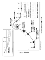
- FIG. 1 is a schematic diagram of a blast furnace to which a blast furnace operating method according to the present invention is applied.
- the blast furnace 1 is provided with a plurality of tuyere in the furnace circumferential direction.
- the tuyere 3 is connected to a blow pipe (blower pipe) 2 for blowing hot air, and the blow pipe 2 has a lance 4 that is mainly inserted obliquely from above toward the center in the tube axis direction. Installed.
- a combustion space called a raceway 5 that is also a coke deposit layer is formed in front of the tuyere 3 where hot air is blown (inside the furnace). In this combustion space, iron ore is mainly reduced, and molten iron is generated. Generate.
- FIG. 2 shows a combustion state when only pulverized coal 6 is blown from the lance 4.
- the pulverized coal 6 passing from the lance 4 through the tuyere 3 and blown into the raceway 5 and the lump coke 7 charged from the top of the furnace are burned here.
- the speed of the hot air in the forward direction of the hot air blown into the furnace from the tuyere 3 is about 200 m / sec, and the region where O 2 exists in the raceway 5 from the tip of the lance 4 is about 0.3-0. Therefore, it is necessary to improve the heating efficiency of pulverized coal particles and the contact efficiency (dispersibility) with oxygen (O 2 ) which is a combustion-supporting gas at a level of 1/1000 second. Become.
- FIG. 3 is an explanatory diagram of a combustion mechanism when only pulverized coal (PC: Pulverized Coal) 6 that is a solid reducing material is blown into the blow pipe 2 from the lance 4.
- PC Pulverized Coal
- the pulverized coal 6 blown into the raceway 5 from the tuyere 3 is heated by the radiant heat transfer from the flame in the raceway 5, and the temperature of the pulverized coal 6 is rapidly increased by the radiant heat transfer and conduction heat transfer.
- Pyrolysis starts when the temperature is raised to 300 ° C. or more, and the volatile matter is ignited to form a flame.
- the combustion temperature particle temperature
- the above-described char 8 is obtained. Since the char 8 is mainly constant carbon, a reaction called a carbon dissolution reaction occurs along with a combustion reaction.
- FIG. 4 shows that LNG, which is a preferred example of a flammable gas reducing material, and oxygen (not shown), which is a preferred example of a combustion-supporting gas, are blown into the blow pipe 2 from the lance 4.
- LNG which is a preferred example of a flammable gas reducing material
- oxygen which is a preferred example of a combustion-supporting gas
- Fig. 5a shows a conventional heavy tube type lance used conventionally.
- FIG. 5b shows the parallel lance proposed in the present invention.
- the heavy tube type lance is a concentric triple tube of an inner tube I, a middle tube M, and an outer tube O in which stainless steel tubes are used, and the dimensions are as shown in the figure.
- the gap between the inner pipe I and the middle pipe M is 1.15 mm, and the gap between the middle pipe M and the outer pipe O is 0.65 mm.
- the solid reducing material blowing tube 21, the gas reducing material blowing tube 22, and the combustion supporting gas blowing tube 23 such as oxygen are arranged in parallel. These are bundled, accommodated in the outer lance tube and integrated, and the dimensions of each blow tube are as shown in the figure.
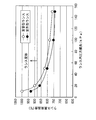
- Fig. 6 shows the results of a comparative measurement of pressure loss between the heavy tube type lance and the parallel type lance.
- the parallel type lance has less pressure loss than the heavy tube type lance.
- the ventilation resistance is reduced by relatively increasing the blowing space (the volume of the blowing pipe).
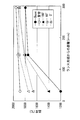
- FIG. 7 shows a comparison of cooling capacity for each lance (heavy tube type, parallel type).
- the parallel lance has a higher cooling capacity at the same pressure loss than the heavy tube lance. This is thought to be because the flow rate that can be flowed at the same pressure loss is large because the in-tube ventilation resistance is small.
- FIG. 8 focuses on the outer diameter of the lance.
- FIG. 8a shows the outer diameter of the non-water-cooled type and
- FIG. 8b shows the outer diameter of the water-cooled type lance.
- the outer diameter of the lance is smaller than that of the heavy tube type lance. This is presumably because the parallel lance can reduce the flow path, the thickness of the pipe, and the cross-sectional area of the water-cooled portion as compared with the heavy tube lance.
- the experimental furnace 11 is filled with lump coke, and the inside of the raceway 15 can be observed from the viewing window.
- a lance 14 is inserted into the blow pipe (blower pipe) 12 so that hot air generated in the combustion burner 13 can be blown into the experimental furnace 11 with a predetermined amount of blown air.
- this ventilation pipe 12 it is also possible to adjust the oxygen enrichment amount of ventilation.
- the lance 14 can blow any one or more of pulverized coal, LNG, and oxygen into the blower pipe 12.
- the exhaust gas generated in the experimental furnace 11 is separated into exhaust gas and dust by a separation device 16 called a cyclone, the exhaust gas is sent to an exhaust gas treatment facility such as an auxiliary combustion furnace, and the dust is collected in a collection box 17. .
- a two-color thermometer is a radiation thermometer that measures temperature using thermal radiation (electromagnetic wave movement from a high-temperature object to a low-temperature object). Focusing on the shift, it is one of the wavelength distribution types to obtain the temperature by measuring the temperature change of the wavelength distribution, and in order to capture the wavelength distribution among them, the radiant energy at two wavelengths is measured and the ratio The temperature is measured from
- pulverized coal is blown from the parallel lance solid reducing agent blowing pipe 21
- LNG is blown from the gas reducing material blowing pipe 22
- combustion supporting gas is injected.
- Oxygen was blown in from the blow-in pipe 23.
- the blowing pipe for solid reducing material and the gas reducing material are used for blowing from the parallel lance.
- the operation is performed in such a manner that the blow-in pipe is positioned above the combustion-supporting gas blow-in pipe. That is, the positional relationship among the fine powder, LNG, and oxygen blown into the blow pipe is such that oxygen is blown to the lower side of the blow pipe near the center of the tube axis, and fine coal and LNG are blown above it.
- Such a positional relationship is such that the parallel lances are in a state where the blowing attitude passes through the tube axis center of the solid reducing material blowing pipe and the outer contact of the lance, and the radial vertical plane of the lance inserted into the blow pipe.
- the lance arrangement is such that the angle between the two and the blow pipes is in a positional relationship of ⁇ 90 °. That is, when the position corresponding to the outer diameter of the lance is the point A on the outer peripheral surface of the blowing pipe 21 into which the pulverized coal is blown, the point A is 0 ° when the point A is at the top, and the point A is the axis of the lance.
- the combustion temperature was measured by a two-color thermometer at a position rotated around 60 ° in the clockwise direction and at a position rotated around 180 ° of point A.
- the insertion length of each lance into the blow pipe was 50 mm.
- the specifications of pulverized coal as the solid reducing material are 71.3% of fixed carbon (FC), 19.6% of volatile matter (VM), 9.1% of ash (Ash), and blown.
- the condition was 50.0 kg / h (corresponding to 158 kg / t per pig iron unit).
- the LNG blowing conditions were 3.6 kg / h (5.0 Nm 3 / h, equivalent to 11 kg / t per pig iron unit).
- the coke used was 150 15 DI83 according to the test method described in JISK2151.
- blowing conditions are as follows: blowing temperature 1100 ° C., flow rate 350 Nm 3 / h, flow rate 80 m / s, O 2 enrichment +3.7 (oxygen concentration 24.7%, air oxygen concentration 21%, 3.7% wealth) ).
- FIG. 11 shows the result of the combustion temperature by the combustion experiment.
- the position of the first pipe of the parallel pipe lance that is, the pulverized coal blowing pipe is changed to 0 °, 60 °, 180 ° around the axis of the lance, 60 °
- the combustion temperature is highest when the pulverized coal and LNG blowing pipes are above the oxygen blowing pipe. This is because the combustion field of LNG is adjacent to pulverized coal, the temperature of pulverized coal is raised, and oxygen is located below LNG and pulverized coal, so that oxygen is efficiently mixed into both LNG and pulverized coal. Therefore, it is considered that combustion was promoted.
- LNG is used as the flammable gas reducing material.
- city gas can also be used, and other gas reducing materials include propane gas, hydrogen, as well as city gas and LNG.
- converter gas, blast furnace gas, and coke oven gas generated at an ironworks can also be used.
- shale gas can be used as equivalent to LNG.
- Shale gas is a natural gas extracted from the shale layer, and is produced from a place other than the conventional gas field, so it is called an unconventional natural gas resource.
- 1 is a blast furnace
- 2 is a blow pipe
- 3 is a tuyere
- 4 is a lance
- 5 is a raceway
- 6 is pulverized coal (solid reducing material)
- 7 is coke
- 8 is char
- 9 is LNG (flammable reducing material) )
Landscapes
- Engineering & Computer Science (AREA)
- Chemical & Material Sciences (AREA)
- Manufacturing & Machinery (AREA)
- Materials Engineering (AREA)
- Metallurgy (AREA)
- Organic Chemistry (AREA)
- Mechanical Engineering (AREA)
- General Engineering & Computer Science (AREA)
- Manufacture Of Iron (AREA)
- Blast Furnaces (AREA)
Abstract
Priority Applications (8)
| Application Number | Priority Date | Filing Date | Title |
|---|---|---|---|
| CN201480019172.1A CN105074014A (zh) | 2013-04-03 | 2014-03-27 | 高炉操作方法及喷枪 |
| AU2014250568A AU2014250568B2 (en) | 2013-04-03 | 2014-03-27 | Blast furnace operation method and lance |
| US14/781,698 US9945001B2 (en) | 2013-04-03 | 2014-03-27 | Blast furnace operation method and lance |
| CA2907833A CA2907833C (fr) | 2013-04-03 | 2014-03-27 | Procede d'exploitation de haut-fourneau et lance |
| EP14780034.6A EP2982768B1 (fr) | 2013-04-03 | 2014-03-27 | Procédé d'exploitation de haut-fourneau et lance |
| KR1020157027225A KR101675710B1 (ko) | 2013-04-03 | 2014-03-27 | 고로 조업 방법 및 랜스 |
| JP2014527377A JP5652575B1 (ja) | 2013-04-03 | 2014-03-27 | 高炉操業方法及びランス |
| RU2015147170A RU2674454C2 (ru) | 2013-04-03 | 2014-03-27 | Способ работы доменной печи и копье |
Applications Claiming Priority (2)
| Application Number | Priority Date | Filing Date | Title |
|---|---|---|---|
| JP2013-077523 | 2013-04-03 | ||
| JP2013077523 | 2013-04-03 |
Publications (1)
| Publication Number | Publication Date |
|---|---|
| WO2014162965A1 true WO2014162965A1 (fr) | 2014-10-09 |
Family
ID=51658263
Family Applications (1)
| Application Number | Title | Priority Date | Filing Date |
|---|---|---|---|
| PCT/JP2014/058797 Ceased WO2014162965A1 (fr) | 2013-04-03 | 2014-03-27 | Procédé d'exploitation de haut-fourneau et lance |
Country Status (9)
| Country | Link |
|---|---|
| US (1) | US9945001B2 (fr) |
| EP (1) | EP2982768B1 (fr) |
| JP (1) | JP5652575B1 (fr) |
| KR (1) | KR101675710B1 (fr) |
| CN (1) | CN105074014A (fr) |
| AU (1) | AU2014250568B2 (fr) |
| CA (1) | CA2907833C (fr) |
| RU (1) | RU2674454C2 (fr) |
| WO (1) | WO2014162965A1 (fr) |
Cited By (1)
| Publication number | Priority date | Publication date | Assignee | Title |
|---|---|---|---|---|
| JP2020117761A (ja) * | 2019-01-23 | 2020-08-06 | Jfeスチール株式会社 | 高炉用羽口、高炉用羽口設備および粒状固体還元材の吹込み方法 |
Families Citing this family (3)
| Publication number | Priority date | Publication date | Assignee | Title |
|---|---|---|---|---|
| CA2907833C (fr) | 2013-04-03 | 2017-01-24 | Jfe Steel Corporation | Procede d'exploitation de haut-fourneau et lance |
| KR101693136B1 (ko) * | 2013-04-03 | 2017-01-04 | 제이에프이 스틸 가부시키가이샤 | 고로 조업 방법 |
| IT202200026757A1 (it) * | 2022-12-23 | 2024-06-23 | Tenova Spa | Lancia di iniezione di materiali solidi in forma di granuli e/o polveri per iniettare materiali solidi in forma di granuli e/o polveri in un forno metallurgico |
Citations (7)
| Publication number | Priority date | Publication date | Assignee | Title |
|---|---|---|---|---|
| JPH1112613A (ja) | 1997-06-27 | 1999-01-19 | Nkk Corp | 高炉の微粉炭吹き込み用ランス |
| JP2001200308A (ja) * | 2000-01-19 | 2001-07-24 | Nkk Corp | 微粉炭吹込みバーナー |
| JP2003286511A (ja) | 2002-03-29 | 2003-10-10 | Nippon Steel Corp | 高炉での低揮発分微粉炭の燃焼性向上方法 |
| JP2004183104A (ja) * | 2003-12-08 | 2004-07-02 | Jfe Steel Kk | 合成樹脂類の処理方法及び設備 |
| JP2007162038A (ja) | 2005-12-09 | 2007-06-28 | Jfe Steel Kk | 高炉への還元材吹込み方法及び装置 |
| JP2010537153A (ja) * | 2007-08-29 | 2010-12-02 | ポスコ | 熔鉄製造用羽口およびこれを利用したガス吹込方法 |
| WO2014010660A1 (fr) * | 2012-07-13 | 2014-01-16 | Jfeスチール株式会社 | Procédé de fonctionnement d'un haut fourneau et canne de type faisceau tubulaire |
Family Cites Families (15)
| Publication number | Priority date | Publication date | Assignee | Title |
|---|---|---|---|---|
| FR2431542A1 (fr) * | 1978-07-19 | 1980-02-15 | Creusot Loire | Tuyere de soufflage |
| SU994561A2 (ru) * | 1981-02-20 | 1983-02-07 | Донецкий Ордена Трудового Красного Знамени Политехнический Институт | Питатель дл подачи угольной пыли |
| JPH0723489B2 (ja) * | 1987-05-30 | 1995-03-15 | 住友金属工業株式会社 | 高炉の微粉炭吹込み用ノズル |
| JPH0338344U (fr) | 1989-08-18 | 1991-04-12 | ||
| FR2681417B1 (fr) * | 1991-09-17 | 1998-01-30 | Air Liquide | Dispositif et procede d'injection de gaz et de charbon dans un four de fusion de metal. |
| JP2868941B2 (ja) | 1991-11-05 | 1999-03-10 | 川崎製鉄株式会社 | 竪型炉の羽口粉粒体吹込方法 |
| IT1302798B1 (it) | 1998-11-10 | 2000-09-29 | Danieli & C Ohg Sp | Dispositivo integrato per l'iniezione di ossigeno e gastecnologici e per l'insufflaggio di materiale solido in |
| JP4779272B2 (ja) | 2001-09-20 | 2011-09-28 | Jfeスチール株式会社 | 高炉内への微粉炭吹き込み方法 |
| RU2245373C1 (ru) * | 2003-04-17 | 2005-01-27 | Открытое акционерное общество "Северсталь" | Дутьевая фурма доменной печи |
| CN200942372Y (zh) * | 2006-06-08 | 2007-09-05 | 云南铜业科技发展股份有限公司 | 管束式冶炼喷枪 |
| JP5824810B2 (ja) | 2010-01-29 | 2015-12-02 | Jfeスチール株式会社 | 高炉操業方法 |
| JP5923968B2 (ja) * | 2010-12-27 | 2016-05-25 | Jfeスチール株式会社 | 高炉操業方法 |
| JP5699832B2 (ja) * | 2011-07-08 | 2015-04-15 | Jfeスチール株式会社 | 高炉操業方法 |
| JP5263430B2 (ja) | 2011-07-15 | 2013-08-14 | Jfeスチール株式会社 | 高炉操業方法 |
| CA2907833C (fr) | 2013-04-03 | 2017-01-24 | Jfe Steel Corporation | Procede d'exploitation de haut-fourneau et lance |
-
2014
- 2014-03-27 CA CA2907833A patent/CA2907833C/fr active Active
- 2014-03-27 WO PCT/JP2014/058797 patent/WO2014162965A1/fr not_active Ceased
- 2014-03-27 US US14/781,698 patent/US9945001B2/en active Active
- 2014-03-27 KR KR1020157027225A patent/KR101675710B1/ko active Active
- 2014-03-27 EP EP14780034.6A patent/EP2982768B1/fr active Active
- 2014-03-27 CN CN201480019172.1A patent/CN105074014A/zh active Pending
- 2014-03-27 JP JP2014527377A patent/JP5652575B1/ja active Active
- 2014-03-27 AU AU2014250568A patent/AU2014250568B2/en active Active
- 2014-03-27 RU RU2015147170A patent/RU2674454C2/ru active
Patent Citations (7)
| Publication number | Priority date | Publication date | Assignee | Title |
|---|---|---|---|---|
| JPH1112613A (ja) | 1997-06-27 | 1999-01-19 | Nkk Corp | 高炉の微粉炭吹き込み用ランス |
| JP2001200308A (ja) * | 2000-01-19 | 2001-07-24 | Nkk Corp | 微粉炭吹込みバーナー |
| JP2003286511A (ja) | 2002-03-29 | 2003-10-10 | Nippon Steel Corp | 高炉での低揮発分微粉炭の燃焼性向上方法 |
| JP2004183104A (ja) * | 2003-12-08 | 2004-07-02 | Jfe Steel Kk | 合成樹脂類の処理方法及び設備 |
| JP2007162038A (ja) | 2005-12-09 | 2007-06-28 | Jfe Steel Kk | 高炉への還元材吹込み方法及び装置 |
| JP2010537153A (ja) * | 2007-08-29 | 2010-12-02 | ポスコ | 熔鉄製造用羽口およびこれを利用したガス吹込方法 |
| WO2014010660A1 (fr) * | 2012-07-13 | 2014-01-16 | Jfeスチール株式会社 | Procédé de fonctionnement d'un haut fourneau et canne de type faisceau tubulaire |
Non-Patent Citations (1)
| Title |
|---|
| See also references of EP2982768A4 |
Cited By (1)
| Publication number | Priority date | Publication date | Assignee | Title |
|---|---|---|---|---|
| JP2020117761A (ja) * | 2019-01-23 | 2020-08-06 | Jfeスチール株式会社 | 高炉用羽口、高炉用羽口設備および粒状固体還元材の吹込み方法 |
Also Published As
| Publication number | Publication date |
|---|---|
| RU2674454C2 (ru) | 2018-12-10 |
| CA2907833C (fr) | 2017-01-24 |
| KR20150123920A (ko) | 2015-11-04 |
| CA2907833A1 (fr) | 2014-10-09 |
| RU2015147170A (ru) | 2017-05-12 |
| US20160040261A1 (en) | 2016-02-11 |
| EP2982768A4 (fr) | 2016-03-30 |
| AU2014250568B2 (en) | 2016-09-15 |
| KR101675710B1 (ko) | 2016-11-11 |
| CN105074014A (zh) | 2015-11-18 |
| AU2014250568A1 (en) | 2015-10-15 |
| EP2982768A1 (fr) | 2016-02-10 |
| US9945001B2 (en) | 2018-04-17 |
| JP5652575B1 (ja) | 2015-01-14 |
| EP2982768B1 (fr) | 2017-05-24 |
| JPWO2014162965A1 (ja) | 2017-02-16 |
Similar Documents
| Publication | Publication Date | Title |
|---|---|---|
| TWI481721B (zh) | Blast furnace operation method | |
| JP5824810B2 (ja) | 高炉操業方法 | |
| JP5699833B2 (ja) | 高炉操業方法 | |
| JP6256710B2 (ja) | 酸素高炉の操業方法 | |
| TWI484041B (zh) | Blast furnace operation method | |
| JP5652575B1 (ja) | 高炉操業方法及びランス | |
| JP2011168885A (ja) | 高炉操業方法 | |
| JP5610109B1 (ja) | 高炉操業方法 | |
| JP2011168886A (ja) | 高炉操業方法 | |
| JP6044564B2 (ja) | 高炉操業方法 | |
| JP5824813B2 (ja) | 高炉操業方法 | |
| JP5983294B2 (ja) | 高炉操業方法及びランス |
Legal Events
| Date | Code | Title | Description |
|---|---|---|---|
| WWE | Wipo information: entry into national phase |
Ref document number: 201480019172.1 Country of ref document: CN |
|
| ENP | Entry into the national phase |
Ref document number: 2014527377 Country of ref document: JP Kind code of ref document: A |
|
| 121 | Ep: the epo has been informed by wipo that ep was designated in this application |
Ref document number: 14780034 Country of ref document: EP Kind code of ref document: A1 |
|
| ENP | Entry into the national phase |
Ref document number: 2907833 Country of ref document: CA |
|
| REEP | Request for entry into the european phase |
Ref document number: 2014780034 Country of ref document: EP |
|
| WWE | Wipo information: entry into national phase |
Ref document number: 2014780034 Country of ref document: EP |
|
| WWE | Wipo information: entry into national phase |
Ref document number: 14781698 Country of ref document: US |
|
| ENP | Entry into the national phase |
Ref document number: 20157027225 Country of ref document: KR Kind code of ref document: A |
|
| NENP | Non-entry into the national phase |
Ref country code: DE |
|
| ENP | Entry into the national phase |
Ref document number: 2014250568 Country of ref document: AU Date of ref document: 20140327 Kind code of ref document: A |
|
| ENP | Entry into the national phase |
Ref document number: 2015147170 Country of ref document: RU Kind code of ref document: A |