WO2014167645A1 - 永久磁石型モータ及び電動パワーステアリング装置 - Google Patents
永久磁石型モータ及び電動パワーステアリング装置 Download PDFInfo
- Publication number
- WO2014167645A1 WO2014167645A1 PCT/JP2013/060679 JP2013060679W WO2014167645A1 WO 2014167645 A1 WO2014167645 A1 WO 2014167645A1 JP 2013060679 W JP2013060679 W JP 2013060679W WO 2014167645 A1 WO2014167645 A1 WO 2014167645A1
- Authority
- WO
- WIPO (PCT)
- Prior art keywords
- permanent magnet
- winding
- phase
- windings
- protrusion
- Prior art date
- Legal status (The legal status is an assumption and is not a legal conclusion. Google has not performed a legal analysis and makes no representation as to the accuracy of the status listed.)
- Ceased
Links
Images









Classifications
-
- H—ELECTRICITY
- H02—GENERATION; CONVERSION OR DISTRIBUTION OF ELECTRIC POWER
- H02K—DYNAMO-ELECTRIC MACHINES
- H02K3/00—Details of windings
- H02K3/04—Windings characterised by the conductor shape, form or construction, e.g. with bar conductors
- H02K3/28—Layout of windings or of connections between windings
-
- H—ELECTRICITY
- H02—GENERATION; CONVERSION OR DISTRIBUTION OF ELECTRIC POWER
- H02K—DYNAMO-ELECTRIC MACHINES
- H02K1/00—Details of the magnetic circuit
- H02K1/06—Details of the magnetic circuit characterised by the shape, form or construction
- H02K1/12—Stationary parts of the magnetic circuit
- H02K1/16—Stator cores with slots for windings
-
- H—ELECTRICITY
- H02—GENERATION; CONVERSION OR DISTRIBUTION OF ELECTRIC POWER
- H02K—DYNAMO-ELECTRIC MACHINES
- H02K1/00—Details of the magnetic circuit
- H02K1/06—Details of the magnetic circuit characterised by the shape, form or construction
- H02K1/22—Rotating parts of the magnetic circuit
- H02K1/27—Rotor cores with permanent magnets
- H02K1/2706—Inner rotors
-
- H—ELECTRICITY
- H02—GENERATION; CONVERSION OR DISTRIBUTION OF ELECTRIC POWER
- H02K—DYNAMO-ELECTRIC MACHINES
- H02K1/00—Details of the magnetic circuit
- H02K1/06—Details of the magnetic circuit characterised by the shape, form or construction
- H02K1/22—Rotating parts of the magnetic circuit
- H02K1/27—Rotor cores with permanent magnets
- H02K1/2706—Inner rotors
- H02K1/272—Inner rotors the magnetisation axis of the magnets being perpendicular to the rotor axis
- H02K1/274—Inner rotors the magnetisation axis of the magnets being perpendicular to the rotor axis the rotor consisting of two or more circumferentially positioned magnets
- H02K1/2753—Inner rotors the magnetisation axis of the magnets being perpendicular to the rotor axis the rotor consisting of two or more circumferentially positioned magnets the rotor consisting of magnets or groups of magnets arranged with alternating polarity
- H02K1/278—Surface mounted magnets; Inset magnets
-
- H—ELECTRICITY
- H02—GENERATION; CONVERSION OR DISTRIBUTION OF ELECTRIC POWER
- H02K—DYNAMO-ELECTRIC MACHINES
- H02K11/00—Structural association of dynamo-electric machines with electric components or with devices for shielding, monitoring or protection
- H02K11/0094—Structural association with other electrical or electronic devices
-
- H—ELECTRICITY
- H02—GENERATION; CONVERSION OR DISTRIBUTION OF ELECTRIC POWER
- H02K—DYNAMO-ELECTRIC MACHINES
- H02K11/00—Structural association of dynamo-electric machines with electric components or with devices for shielding, monitoring or protection
- H02K11/20—Structural association of dynamo-electric machines with electric components or with devices for shielding, monitoring or protection for measuring, monitoring, testing, protecting or switching
- H02K11/21—Devices for sensing speed or position, or actuated thereby
- H02K11/215—Magnetic effect devices, e.g. Hall-effect or magneto-resistive elements
-
- H—ELECTRICITY
- H02—GENERATION; CONVERSION OR DISTRIBUTION OF ELECTRIC POWER
- H02K—DYNAMO-ELECTRIC MACHINES
- H02K11/00—Structural association of dynamo-electric machines with electric components or with devices for shielding, monitoring or protection
- H02K11/30—Structural association with control circuits or drive circuits
- H02K11/33—Drive circuits, e.g. power electronics
-
- H—ELECTRICITY
- H02—GENERATION; CONVERSION OR DISTRIBUTION OF ELECTRIC POWER
- H02K—DYNAMO-ELECTRIC MACHINES
- H02K29/00—Motors or generators having non-mechanical commutating devices, e.g. discharge tubes or semiconductor devices
- H02K29/03—Motors or generators having non-mechanical commutating devices, e.g. discharge tubes or semiconductor devices with a magnetic circuit specially adapted for avoiding torque ripples or self-starting problems
-
- H—ELECTRICITY
- H02—GENERATION; CONVERSION OR DISTRIBUTION OF ELECTRIC POWER
- H02K—DYNAMO-ELECTRIC MACHINES
- H02K29/00—Motors or generators having non-mechanical commutating devices, e.g. discharge tubes or semiconductor devices
- H02K29/06—Motors or generators having non-mechanical commutating devices, e.g. discharge tubes or semiconductor devices with position sensing devices
- H02K29/08—Motors or generators having non-mechanical commutating devices, e.g. discharge tubes or semiconductor devices with position sensing devices using magnetic effect devices, e.g. Hall-plates, magneto-resistors
-
- H—ELECTRICITY
- H02—GENERATION; CONVERSION OR DISTRIBUTION OF ELECTRIC POWER
- H02K—DYNAMO-ELECTRIC MACHINES
- H02K7/00—Arrangements for handling mechanical energy structurally associated with dynamo-electric machines, e.g. structural association with mechanical driving motors or auxiliary dynamo-electric machines
- H02K7/14—Structural association with mechanical loads, e.g. with hand-held machine tools or fans
-
- H—ELECTRICITY
- H02—GENERATION; CONVERSION OR DISTRIBUTION OF ELECTRIC POWER
- H02K—DYNAMO-ELECTRIC MACHINES
- H02K2201/00—Specific aspects not provided for in the other groups of this subclass relating to the magnetic circuits
- H02K2201/03—Machines characterised by aspects of the air-gap between rotor and stator
-
- H—ELECTRICITY
- H02—GENERATION; CONVERSION OR DISTRIBUTION OF ELECTRIC POWER
- H02K—DYNAMO-ELECTRIC MACHINES
- H02K2213/00—Specific aspects, not otherwise provided for and not covered by codes H02K2201/00 - H02K2211/00
- H02K2213/03—Machines characterised by numerical values, ranges, mathematical expressions or similar information
-
- H—ELECTRICITY
- H02—GENERATION; CONVERSION OR DISTRIBUTION OF ELECTRIC POWER
- H02K—DYNAMO-ELECTRIC MACHINES
- H02K2213/00—Specific aspects, not otherwise provided for and not covered by codes H02K2201/00 - H02K2211/00
- H02K2213/12—Machines characterised by the modularity of some components
Definitions
- the present invention relates to a rotation in which a magnetic projection is provided between a stator in which multiple multiphase windings are wound around a stator core, and a permanent magnet having a different polarity arranged adjacent to the rotor core.
- the present invention relates to a permanent magnet type motor composed of a child and an electric power steering apparatus equipped with the same.
- Patent Document 1 discloses a multi-phase winding motor having a multi-phase winding group composed of a multi-phase winding and an inverter for driving the multi-phase winding in a single AC motor. ing.
- the torque of the entire motor is obtained by energizing the inverters so that the torque ripple generated by one multiphase winding and the torque ripple generated by another multiphase winding are in opposite phases. Ripple can be offset.
- the present invention provides a permanent magnet type motor capable of ensuring the controllability of the motor and an electric power steering apparatus equipped with the permanent magnet type motor.
- the permanent magnet type motor according to the present invention has a magnetic projection between adjacent permanent magnets for a multiplex multiphase winding AC motor, so that the reluctance torque can be increased in each multiphase winding, The motor output can be increased.
- a permanent magnet on the surface of the rotor core, the magnetic gap between the rotor and the stator can be increased, and a non-magnetic gap is provided between the permanent magnet and the protrusion. Therefore, magnetic coupling between multiphase windings, that is, an increase in mutual inductance can be suppressed, so even when the current control response frequency is high, disturbance voltages are unlikely to overlap each other between the multiphase windings, thus canceling out the torque ripple.
- Such motor control becomes possible.
- the same effect can be achieved also in the electric power steering apparatus equipped with the permanent magnet type motor according to the present invention.
- FIG. 3 is an explanatory diagram showing an equivalent circuit of armature windings between a set of multiple multiphase winding AC motors in the first embodiment.
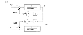
- FIG. 3 is an explanatory diagram showing a q-axis equivalent circuit configuration of the multiple multiphase winding AC motor according to the first embodiment.
- FIG. 3 is an explanatory diagram illustrating a configuration of the electric drive device according to the first embodiment.
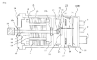
- 1 is a cross-sectional view showing a configuration of a multi-phase winding permanent magnet type motor in Embodiment 1.
- FIG. 3 is a circuit diagram illustrating a method for driving the multiplex multiphase winding AC motor according to Embodiment 1.
- FIG. 3 is an explanatory diagram showing torque characteristics of the multiplex multiphase winding AC motor according to Embodiment 1.
- FIG. It is explanatory drawing which simplifies and shows the rotor which concerns on Embodiment 2.
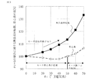
- FIG. 9 is a diagram showing the no-load rotation speed and the iron core length when the electrical angle ⁇ t occupied by the surface of the protruding portion facing the stator iron core is changed.
- FIG. 10 is an explanatory diagram illustrating a rotor according to a third embodiment in a simplified manner.
- FIG. 10 is an explanatory diagram illustrating a rotor according to a third embodiment in a simplified manner.
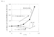
- FIG. 11 is a diagram illustrating the no-load rotation speed and the iron core length when the thickness h of the permanent magnet is constant and the height h of the protrusion is changed.
- FIG. 10 is an explanatory diagram illustrating a rotor according to a fourth embodiment in a simplified manner. It is a figure which shows the change of the rated torque at the time of changing the space
- FIG. 10 is an explanatory diagram showing a configuration of a rotor in a fifth embodiment.
- FIG. 3 is a perspective view showing a rotor in the first embodiment.
- FIG. 10 is a perspective view showing a rotor in a sixth embodiment.
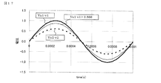
- FIG. 4 is an explanatory diagram illustrating a voltage waveform of a motor terminal in the first embodiment. It is explanatory drawing which shows the structure of a general electric power steering apparatus.
- FIG. FIG. 18 is an explanatory diagram showing a configuration of a general electric power steering device of an automobile.
- the driver steers a steering wheel (not shown), and the torque is transmitted to the shaft 3 via a steering shaft (not shown).
- the torque detected by the torque sensor 4 is converted into an electric signal and transmitted to an ECU (Electronic Control Unit) through the connector 1 through a cable (not shown).
- the ECU includes an inverter circuit that drives the control board and the motor.
- vehicle information such as vehicle speed is converted into an electrical signal and transmitted to the ECU via the connector 2.
- the ECU calculates necessary assist torque from the vehicle information such as the torque and the vehicle speed, and supplies current to the permanent magnet type motor 5 through the inverter.
- the permanent magnet type motor 5 is arranged in a direction parallel to the movement direction Dr (indicated by an arrow) of the rack shaft.
- the power supply to the ECU is sent from the battery or alternator via the power connector 6.
- the torque generated by the motor 5 is decelerated by a gear box 7 containing a belt (not shown) and a ball screw (not shown), and a rack shaft (not shown) inside the housing 8 is moved in the direction of the arrow Dr.
- Thrust is generated to assist the driver's steering force.
- the tie rod 9 moves, the tire can steer and the vehicle can be turned.
- the rack boot 10 is provided so that foreign matter does not enter the apparatus.
- the motor 5 and the ECU are integrated to constitute an electric drive device.
- the bearing 15a together with the bearing 15b, rotatably supports a rotating shaft (shaft) 16.
- the bearing 15b is supported by a wall portion 17 provided integrally with the frame 13 or separately.
- a rotor core 18 is press-fitted into the shaft 16, and a permanent magnet 19 is fixed to the rotor core 18.
- a pulley 20 that drives the rack shaft is coupled to the front end of the shaft 16.
- a sensor permanent magnet 21 is coupled to the rear end of the shaft 16.
- the frame 13 is fixed by a housing that also serves as a heat sink 24 provided on the rear surface of the motor 5.
- a case 25 is hermetically fixed to the rear surface of the heat sink 24.
- a control board 26 of the ECU and a switching element 27 constituting an inverter circuit for driving the motor 5 are housed with an intermediate member 34 interposed.
- the switching element 27 dissipates heat generated by being placed on the heat sink 24.
- a sensor unit 28 that detects the rotational position of the motor 5 is provided with a substrate 30 with a magnetic sensor 29 facing the sensor permanent magnet 21 coupled to the shaft 16, and the rotational position of the motor 5 detected by the magnetic sensor 29. Is output to the control board 26 via the connection member 31.
- Reference numeral 32 denotes a support part for fixing the connection member 31 to the substrate 30, and 33 denotes a recess 33 provided in the heat sink 24 with respect to the substrate 30.
- FIG. 5 is a cross-sectional view showing the configuration of a multi-phase winding permanent magnet motor.
- a stator 42 is provided on the outer peripheral side of the rotor 41, and the stator 42 has an armature winding 12 and a stator core 11.
- the stator core 11 includes an annular core back 43 made of a magnetic material such as an electromagnetic steel plate, and teeth 44 extending from the core back 43 to the inner peripheral side.
- the armature winding 12 is accommodated in a slot 45 provided between adjacent teeth 44.
- insulating paper or the like is inserted between the armature winding 12 and the stator core 11 to ensure electrical insulation. For example, a total of 48 teeth 44 are provided, and therefore the number of slots 45 is also 48. Slot numbers 1 to 48 are assigned to the slots 45. In the slot 45, the coil of the armature winding 12 is accommodated.
- the first armature winding set is composed of three phases U1, V1 and W1 (see FIG. 1), and the second armature winding set is composed of U2, V2 and W2 phases. It is configured. As shown in FIG. 5, the windings are arranged in the order of U1, U2, W1, W2, V1, V2 from the first slot, and in the order of U1, U2, W1, W2, V1, V2 after the seventh slot. Arranged in the same order up to the 48th. That is, the first armature winding and the second armature winding are disposed in adjacent slots. However, the armature windings are arranged so that the current directions of U1 of the first slot and U1 of the seventh slot are opposite to each other.
- a rotor 41 including a permanent magnet 19 facing the stator core is provided on the surface of the rotor core 18.
- Eight permanent magnets 19 are arranged in the circumferential direction. The polarities of adjacent permanent magnets 19 are opposite to each other.
- protrusions 46 are provided between the permanent magnets 19 on the surface of the rotor core 18.
- a non-magnetic gap 47 for reducing leakage magnetic flux is provided between the projection 46 and the permanent magnet 19 on both sides of the projection 46.
- the protrusion 46 has the effect of reducing the gap of the motor 5 and increases the inductance. As a result, the flux-weakening control can easily exert an effect, and there is an effect that the torque can be improved during high-speed rotation.
- the rotor core 18 is configured by laminating electromagnetic steel plates and the like, and the electromagnetic steel plates are connected to each other by a crimping portion (not shown).
- a shaft 16 passes through the center of the rotor core 18.
- a metal protective tube may be provided so as to cover the outer periphery of the permanent magnet 19 in order to prevent the permanent magnet 19 from scattering.
- the protective tube is made of a nonmagnetic metal such as aluminum or SUS (stainless steel).
- FIG. 6 is a circuit diagram illustrating a method for driving the multi-phase winding AC motor according to the first embodiment.
- the 6-phase (U1, V1, W1, U2, V2, W2) armature windings of the multi-phase winding AC motor 5 are connected to the three-phase terminals (U1 ′, V1) of the first inverter. ', W1'), U1 and U1 ', U2 and U2', V1 and V1 ', V2 and V2', W1 and W1 ', W2 on the three-phase terminals (U2', V2 ', W2') of the second inverter And W2 ′ are connected to each other.
- the magnetic flux generated by the multi-phase winding group is linked to the other multi-phase winding group, so that the other multi-phase windings are combined.
- a voltage is generated in the wire set. This is superimposed as a disturbance on the voltage applied to the other multi-phase winding set by the inverter, so that the motor control that cancels the torque ripple generated by each multi-phase winding set in the opposite phase is more effective. There was a problem of becoming difficult.
- FIG. 1 is an explanatory view showing a connection method of armature windings of a motor having a double three-phase winding.
- FIG. 1A is an explanatory diagram of ⁇ connection
- FIG. 1B is an explanatory diagram of Y connection.
- the present invention can be applied to both ⁇ connection and Y connection.
- An equivalent circuit of the U1 phase of the first winding group (first armature winding group) and the U2 phase armature winding of the second winding group (second armature winding group) is expressed as shown in FIG. be able to.
- first armature winding group first armature winding group
- second armature winding group second armature winding group
- Vu represents each terminal voltage of the winding
- Iu current
- R represents resistance
- Ve represents induced voltage
- lm leakage inductance
- M represents mutual inductance
- subscripts 1 and 2 represent primary sides, respectively.
- Secondary side. N is a turn ratio referred to as a transformer. Of these values, especially lm and M are different from values used in normal motor control, and indicate the inductances between multiple two phases arranged in parallel.
- n 1.
- Equivalent circuit of V1 phase and V2 phase, W1 phase and W2 phase, U1 phase and V2 phase, U1 phase and W2 phase, V1 phase and U2 phase, V1 phase and W2 phase, W1 phase and U2 phase, W1 phase and V2 phase 2 is also the same as FIG. 2, so in the case of three-phase equilibrium, even if coordinate conversion is performed from the UVW three-phase to the dq axis of the rotor, the equivalent circuit on this dq axis is the same as the equivalent circuit shown in FIG. Become.
- FIG. 3 shows the equivalent circuit of the q-axis in the form of a block diagram when the coordinates are converted to the rotor dq-axis.
- vq1 and vq2 are q-axis voltages of the first winding group and the second winding group
- iq1 and iq2 are q-axis currents of the first winding group and the second winding group, respectively
- Lq1 and Lq2 are respectively Q-axis components of the self-inductance of the windings of the first winding set and the second winding set
- Ra1 and Ra2 are resistance components of the windings of the first winding set and the second winding set
- Mq12 and Mq21 are the first It is the q-axis component of the mutual inductance of the winding between the winding set and the second winding set.
- s represents a differential operator of Laplace transform.
- vq12 and vq21 are disturbance voltages superimposed on the first winding group and the second winding group due to the mutual inductance between the first winding group and the second winding group, respectively.
- FIG. 3 shows an equivalent circuit on the rotor q-axis, but the equivalent circuit on the rotor d-axis has the same configuration. Since the disturbance voltage is proportional to the differential value s, which is the control response frequency of the current, it increases as the current is controlled at high speed by motor control, making motor control that cancels torque ripple at a high response frequency difficult. .
- the amount of voltage supplied to the motor is limited, and thus the dependency on the rotational speed of the torque is limited. large. That is, in order to increase the output of the motor, it is necessary to improve both the torques in the operation region A and the operation region B having different drive conditions.
- the torque T of the multiplex multiphase winding AC motor of the first embodiment is expressed as follows.
- ⁇ m in equation (1) is the amount of magnetic flux generated by the permanent magnet
- id and iq are the d-axis and q-axis currents supplied to the multi-phase winding, respectively
- P is the number of magnetic poles of the multi-phase winding AC motor.
- one item on the right side is magnet torque, and two items are reluctance torque.
- armature made of a magnetic material protruding from a rotor core (field magnetic core) 18 is disposed between adjacent permanent magnets 19.
- disturbance voltages interact with each other to obtain disturbance values iq1 ′ and iq2 ′ for the current control system.
- the disturbance values iq1 ′ and iq2 ′ are expressed as follows from the q-axis equivalent circuit block diagram of FIG.
- iq1 and iq2 are q-axis currents of the respective windings of the first winding group and the second winding group
- Ra1 and Ra2 are resistances of the windings of the first winding group and the second winding group, respectively.
- Lq1 and Lq2 are q-axis components of the self-inductance of each of the first winding group and the second winding group
- Mq12 is the winding of the first winding group and the second winding group. It is a q-axis component of mutual inductance representing interference.
- the Laplace transform differential operator s is increased, and the disturbance value is substantially dependent on the magnetic coupling Mq12 / Lq1 or the magnetic coupling Mq12 / Lq2 from the above equation. It is clear.
- the disturbance value increases.
- the response of the current control system cannot be increased, and the controllability of the motor deteriorates.
- the armature according to the first embodiment may be considered as Mq12 / Lq1 ⁇ Mq12 / Lq2 because the first winding group and the second winding group are symmetrical structures. Therefore, the magnetic coupling will be described for Mq12 / Lq1.
- the armature coils U1 and U2 are arranged in adjacent slots, and ⁇ is represented by the following expression when the angle between the adjacent slots is ⁇ (electrical angle).
- P is the number of magnetic poles of the multiphase winding AC motor
- N is the number of slots
- ⁇ 30 degrees (electrical angle).
- Equation (5) is a relational expression regarding magnetic flux, but the same relational expression holds for the voltage Vu2 generated in the armature coil U2 when the voltage Vu1 is applied to the armature coil U1. This shows that the same relational expression holds for the voltage generated at U2-V2 of the second winding set when U1-V1 of the first winding set of the motor is excited.
- the magnetic coupling is reduced by devising the structure on the rotor 41 side.
- the rotor 41 has a permanent magnet 19 disposed on the surface of the rotor core 18.
- Eight permanent magnets 19 are arranged in the circumferential direction, and the magnetization directions of the permanent magnets 19 are magnetized so that the magnetization directions of the permanent magnets 19 adjacent in the circumferential direction are opposite to each other. Since the magnetic gap between the rotor 41 and the stator 42 can be increased by disposing the permanent magnet 19 on the surface of the rotor core 18, the magnetic coupling between the first winding group and the second winding group is reduced. The effect that it can be obtained.
- a protrusion 46 is provided between the adjacent permanent magnets 19.
- the protrusion 46 is made of a magnetic material.
- the rotor core 18 is configured by laminating steel plates such as electromagnetic steel plates and SPCC (cold rolled steel plates), and the protrusions 46 are configured to be integrated by punching the electromagnetic steel plates and SPCC with a die. The Since the protrusions 46 are provided, the inductance can be improved, the effect of weakening magnetic flux control can be easily exhibited, and the torque at high speed rotation can be improved. In addition, reluctance torque can be generated, the motor torque can be improved, and the amount of permanent magnet 19 used can be reduced.
- nonmagnetic gap portions 47 are provided on both sides of the protrusion 46.
- the gap 47 may be an air gap (air), or may be made of a nonmagnetic metal such as aluminum or SUS (stainless steel) or a resin. When the gap 47 is a gap, the weight can be reduced.
- the presence of the nonmagnetic gap portion 47 can reduce the leakage magnetic flux generated between the permanent magnet 19 and the protrusion 46. Therefore, there is an effect that the torque can be improved and the usage amount of the permanent magnet 19 can be reduced.
- the non-magnetic gap 47 also acts as a magnetic gap between the stator 42 and the rotor 41, thereby reducing the magnetic coupling between the windings of the first winding group and the second winding group. There is an effect that can be done.
- FIG. 15 is a perspective view showing the rotor in the first embodiment.
- the nonmagnetic gap 47 provided between the permanent magnet 19 and the protrusion 46 is provided over the entire axial direction.
- the nonmagnetic gap portion 47 is not necessarily provided over the entire axial direction. If the width of the protruding portion 46 is increased in a part of the axial direction so as to contact the side surface of the permanent magnet 19, the permanent magnet 19 can be positioned in the circumferential direction. Position accuracy can be improved. As a result, there is an effect that torque ripple caused by unbalance on the rotor side can be reduced.
- the controllability can be improved. As a result, the voltage Vu2-v2 generated at the U2-V2 terminal of the second winding set when the U1-V1 terminal of the first winding set of the motor is excited with the voltage Vu1-v1.
- FIG. 17 shows a voltage waveform when an AC voltage is applied to the motor terminal of the first winding group and the voltage of the motor terminal of the second winding group is measured.
- the voltage on the vertical axis is normalized so that Vu1-v1 is 1.
- the frequency of the voltage was set to 1 kHz as a high frequency so that the resistance with respect to the reactance of the armature winding can be ignored.
- the voltage waveform was a sine wave. From FIG. 17, Vu2-v2 is sufficiently smaller than the value obtained by multiplying Vu1-v1 by 0.866. Therefore, the condition of Equation (9) is satisfied, and the interval between the first winding group and the second winding group is satisfied. It can be seen that a motor with small magnetic coupling and good controllability was obtained.
- the multi-phase winding AC motor having 8 poles and 48 slots in which the winding sets have an electrical phase difference of 30 ° has been described.
- the multi-phase winding is not limited to the phase difference, the number of poles, and the number of slots, but the winding is electrically separated into two and each winding set is driven by a different motor driving device For the line AC motor, the same effect as described above can be obtained.
- the armature winding is wound across a plurality of teeth 44
- the winding pitch of the armature winding is a full-pitch winding with an electrical angle of 180 °
- the same effect as described above can be obtained even when the electrical angle is other than 180 °.
- the multi-phase winding AC motor is described in which the windings are electrically separated into two winding sets and are driven by two different motor driving devices. The same effect as described above can be obtained when the number of winding sets separated and the number of motor driving devices are increased.
- the multi-phase winding AC motor of Embodiment 1 is applied to an electric power steering apparatus, torque ripple can be reduced and the steering feeling of the driver can be improved. Further, it is possible to improve the quietness of a vehicle equipped with the electric power steering device. Since the output of the multi-phase winding AC motor is improved, the electric power steering device can be reduced in size and weight, and the vehicle equipped with the electric power steering device can be reduced in size and weight.
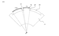
- FIG. 8 shows the structure of the rotor, and only two poles are shown for simplicity.
- the angle occupied by the surface of the projection 46 facing the stator core is ⁇ t.
- FIG. 9 is a diagram showing the no-load rotation speed and the iron core length (the length of the iron core in the rotation axis direction) when ⁇ t is changed in FIG.
- ⁇ t is expressed in electrical angle.
- the width ⁇ t of the protrusion 46 As the width ⁇ t of the protrusion 46 is increased from 0, the width of the protrusion 46 increases, so that the reluctance torque can be used instead of the magnet torque. And the no-load rotation speed increases.
- the motor core length When 0 ⁇ t ⁇ 50 (degrees), the motor core length can be reduced, and at the same time, the no-load rotational speed is increased.
- the reluctance torque can be used in the operation region B (high speed region), the magnet torque can be used in the operation region A (low rotation region), and the torque in the operation region B can be increased without increasing the rotation shaft length as compared with the case where no protrusion is provided. It can be improved.
- the magnetic gap between the rotor 41 and the stator 42 can be increased by arranging the permanent magnet 19 on the surface of the rotor core as described above, the first winding group and the second winding group The effect that magnetic coupling can be reduced is obtained.
- the non-magnetic gap 47 is provided between the permanent magnet 19 and the protrusion 46, the leakage magnetic flux generated between the permanent magnet 19 and the protrusion 46 can be reduced, and at the same time, the non-magnetic gap 47 Since this also acts as a magnetic gap between the stator 42 and the rotor 41, the magnetic coupling between the armature coils of the first winding group and the second winding group can be reduced.
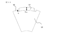
- FIG. 10 shows the structure of the rotor, and only one pole is shown for simplicity.
- the thickness of the permanent magnet 19 is Tm
- the height of the protrusion 46 (the height of the protrusion 46 from the lower end surface of the permanent magnet) is h.
- the reluctance torque can be used instead of the magnet torque, the iron core length decreases, the winding resistance also decreases, and the no-load rotation speed becomes larger.
- h / Tm 1, that is, when the height of the protrusion 46 is equal to the thickness of the permanent magnet 19, the iron core length is minimum.
- a motor having a large saliency such as a reluctance motor has a large torque ripple, so the range of h / Tm> 1 is not desirable because the steering feeling is deteriorated, and the range of 0 ⁇ h / Tm ⁇ 1 is a motor control.
- the length of the iron core can be shortened compared to the case where there is no protrusion 46, and therefore the motor can be reduced in size, which is advantageous in terms of fuel efficiency improvement and attachment.
- the magnetic gap between the rotor 41 and the stator 42 can be increased, so that the first winding group and the second winding group The magnetic coupling can be reduced.
- the non-magnetic gap 47 is provided between the permanent magnet 19 and the protrusion 46, the leakage magnetic flux generated between the permanent magnet 19 and the protrusion 46 can be reduced, and at the same time, the non-magnetic gap 47 Since this also acts as a magnetic gap between the stator 42 and the rotor 41, the magnetic coupling between the armature coils of the first winding group and the second winding group can be reduced.
- FIG. 12 shows the structure of the rotor, and only one pole is shown for simplicity.
- the angles in the circumferential direction of the nonmagnetic gap portion 47 between the permanent magnet 19 and the protrusion 46 are denoted by ⁇ a1 and ⁇ a2.
- ⁇ a1 ⁇ a2.
- FIG. 13 is a diagram showing a change in the rated torque when the distance between the permanent magnet 19 and the protrusion 46, that is, the circumferential angle of the nonmagnetic gap 47 is changed while the width of the protrusion 46 is constant. .
- the value is a ratio when the interval is zero and 100%.
- the interval ⁇ a As the interval ⁇ a increases from 0, the amount of magnetic flux of the permanent magnet 19 leaking in the rotor 41 decreases, so the amount of magnetic flux contributing to the torque increases and the rated torque increases. If the interval ⁇ a exceeds 10 degrees, the permanent magnet 19 magnetic flux that contributes to torque decreases, so the effect of decreasing the permanent magnet 19 magnetic flux itself increases. When the interval ⁇ a exceeds 20 degrees, the rated torque is reduced as compared with the case of the interval 0.
- the range of 0 ⁇ a ⁇ 20 ° is the optimum range for increasing the rated torque. Further, as described above, by arranging the permanent magnet 19 on the surface of the rotor core 18, the magnetic gap between the rotor 41 and the stator 42 can be increased, so that the first winding group and the second winding group The effect that magnetic coupling can be reduced is obtained.
- non-magnetic gap 47 is provided between the permanent magnet 19 and the protrusion 46, the leakage magnetic flux generated between the permanent magnet 19 and the protrusion 46 can be reduced, and at the same time, this non-magnetic gap Since 47 also acts as a magnetic gap between the stator 42 and the rotor 41, the magnetic coupling between the armature coils of the first winding group and the second winding group can be reduced.
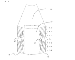
- FIG. 14 shows a structure in which the iron core with the protrusions 46 and the iron core without the protrusions 46 or with a small protrusion 46 or the iron cores having the protrusions 46 serving as permanent magnet pressers are combined and laminated in the fifth embodiment. It is explanatory drawing. For simplification, only one pole is shown.
- the portions indicated by A ⁇ b> 1 and A ⁇ b> 2 are regions where the protrusion 46 is in contact with the permanent magnet 19 and there is no nonmagnetic gap 47.
- the portions indicated by B1 and B2 are regions where nonmagnetic gap portions 47 are provided.
- the portions indicated by C1 and C2 are regions provided with nonmagnetic gap portions 47 wider than B1 and B2.
- D is an area without the protrusion 46.
- the protrusions 46 in the areas indicated by A 1 and A 2 can be used for positioning the permanent magnet 19. Also, torque ripple and cogging torque can be changed if the shape, such as the width and height of the protrusion 46, is different.
- the torque ripple and cogging torque can be reduced by combining them in the direction of the rotation axis as shown in FIG. The effect that it can be obtained.
- the rotor core 18 as shown in FIG. 14 can be laminated by devising the configuration of the mold, and the above-described effects can be obtained without significantly increasing the cost.
- FIG. 16 is a perspective view showing a rotor in which a nonmagnetic gap portion is constituted by a resin member 48.
- the nonmagnetic gap portion is disposed so that the resin member abuts against the side surface of the permanent magnet 19.
- the permanent magnet 19 can be positioned in the circumferential direction, and manufacturing variations on the rotor side can be reduced, so that a motor having a small cogging torque and torque ripple can be obtained.
- the effect of preventing the permanent magnet 19 from scattering can be obtained. Further, if the adhesive is omitted, an effect that production cost and material cost can be reduced can be obtained. The same effect can be obtained with the gap portion 47 of the nonmagnetic portion, not limited to resin, but also with a metal such as nonmagnetic aluminum or SUS. However, since resin is lighter than metal, it has the effect of reducing motor weight and reducing inertia. It should be noted that the present invention can be freely combined with each other within the scope of the invention, and each embodiment can be appropriately modified or omitted.
Landscapes
- Engineering & Computer Science (AREA)
- Power Engineering (AREA)
- Microelectronics & Electronic Packaging (AREA)
- Permanent Magnet Type Synchronous Machine (AREA)
- Iron Core Of Rotating Electric Machines (AREA)
- Permanent Field Magnets Of Synchronous Machinery (AREA)
- Control Of Ac Motors In General (AREA)
Abstract
Description
本発明は、前記課題に鑑み、モータの制御性を確保し得る永久磁石型モータ及びこれを搭載した電動パワーステアリング装置を提供するものである。
前記回転子鉄心の表面部には、永久磁石が周方向に配置され、隣り合う前記永久磁石の極性が互いに逆であり、隣り合う前記永久磁石の間には、前記回転子鉄心から突設された磁性体からなる突起部が設けられ、前記突起部と前記永久磁石との間には回転軸方向の全部又は一部に非磁性のギャップ部が介在しているものである。
本発明の上記以外の目的、特徴、観点及び効果は、図面を参照する以下の本発明の詳細な説明から、さらに明らかになるであろう。
図18は自動車の一般的な電動パワーステアリング装置の構成を示す説明図である。運転者はステアリングホイール(図示しない)を操舵し、そのトルクがステアリングシャフト(図示しない)を介してシャフト3に伝達される。このときトルクセンサ4が検出したトルクは電気信号に変換されケーブル(図示しない)を通じてコネクタ1を介してECU(Electronic Control Unit)に伝達される。ECUは制御基板とモータを駆動するインバータ回路を備えている。一方、車速などの自動車の情報が電気信号に変換されコネクタ2を介してECUに伝達される。ECUはこのトルクと車速などの自動車の情報から、必要なアシストトルクを演算し、インバータを通じて永久磁石型モータ5に電流を供給する。

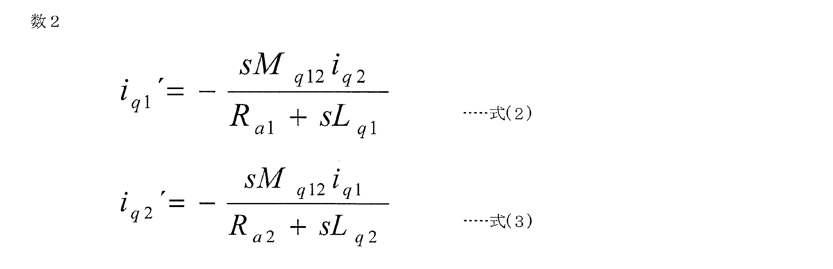





図8は回転子の構造を示し、簡略化のため2極分のみを示す。突起部46において固定子鉄心に対向する面の占める角度をθtとする。図9は図8においてθtを変化させたときの無負荷回転数、鉄心長(鉄心の回転軸方向の長さ)を示す図である。値は突起部46を設けない場合、すなわちθt=0のときの値に対する比率である。θtは電気角で表している。永久磁石19はモータ断面(回転軸に垂直は断面)での断面積が一定となる条件を課しており、定格トルクがθt=0の場合と等しくなるように鉄心長を調整している。突起部46の幅θtを0から大きくしていくと、突起部46の幅が増していくので、マグネットトルクに代わってリラクタンストルクを利用できるようになるので、鉄心長が減少し、巻線抵抗も減少し、無負荷回転数が大きくなる。0<θt≦50(度)とするとモータ鉄心長を小さくできると同時に無負荷回転数が大きくなる。運転領域B(高速領域)ではリラクタンストルク、運転領域A(低回転領域)はマグネットトルクを利用でき、回転軸長を突起部を設けない場合と比較して増加させずに運転領域Bのトルクを向上できる。
図10は回転子の構造を示し、簡略化のため1極分のみを示す。永久磁石19の厚さをTm、突起部46の高さ(突起部46の永久磁石の下端面からの高さ)をhとする。図11は永久磁石19の厚さTmを一定として突起部46の高さhを変えたときの無負荷回転数、鉄心長を示す図である。値は突起部46がない場合h=0に対する比率である。永久磁石19はモータ断面での断面積が一定となる条件を課しており、定格トルクがh=0の場合と等しくなるように鉄心長を調整している。
図12は回転子の構造を示し、簡略化のため1極分のみを示す。永久磁石19と突起部46の間の非磁性のギャップ部分47の周方向の角度をθa1,θa2とする。ここではθa1=θa2としている。θa1=θa2とすることで、磁気的なバランスが取れるためトルクリップルが小さくできるという効果がある。図13は突起部46の幅を一定としたまま、永久磁石19と突起部46の間隔すなわち非磁性のギャップ部47の周方向の角度を変化させた場合の定格トルクの変化を示す図である。値は間隔がゼロの時を100%とした場合の比率である。横軸のθaはθa=θa1+θa2として定義している。
これまでの実施の形態1~4では非磁性のギャップ部47がモータの回転軸方向に均一に設けられた例について述べたが、これに限らない。図14は実施の形態5における突起部46のある鉄心と、突起部46のない、もしくは突起部46の小さな鉄心、又は永久磁石押さえとなる突起部46を有する鉄心を組み合わせて積層した構成を示す説明図である。簡略化のため1極分のみ示している。
これまでの実施の形態1~5では、永久磁石19と回転子鉄心18の突起部46の間の非磁性のギャップ部は空気である例について述べてきた。しかし、本発明はそれに限らない。図16は非磁性のギャップ部を樹脂部材48で構成した回転子を示す斜視図である。非磁性のギャップ部は樹脂部材が永久磁石19の側面に当接するように配置されている。これにより、永久磁石19の周方向の位置決めが可能となり、回転子側の製造ばらつきを低減できるため、コギングトルクやトルクリップルの小さいモータを得ることができるという効果がある。また、樹脂部材48によって永久磁石19の径方向を固定することで、永久磁石19の飛散防止の効果が得られる。また、接着剤を省略すれば、生産コストや材料コストを低減できるという効果が得られる。非磁性部のギャップ部47は樹脂に限らず、非磁性のアルミニウム,SUSなどの金属でも同じ効果が得られる。ただし、樹脂は金属と比べて軽量であるため、モータの軽量化やイナーシャ低減の効果がある。
なお、本発明は、その発明の範囲内において、各実施の形態を自由に組み合わせたり、各実施の形態を適宜、変形、省略することが可能である。
Claims (11)
- 電機子巻線がスロットに収められた固定子鉄心を有する固定子と、前記固定子の内周側にエアギャップを介して前記固定子と対向する回転子鉄心を有し、回転軸で回転自在に支承される回転子とを備え、
前記電機子巻線は複数組の多相巻線であり、
前記電機子巻線の複数組はそれぞれ個別のインバータから電流が供給され、
前記回転子鉄心の表面部には、永久磁石が周方向に配置され、隣り合う前記永久磁石の極性が互いに逆であり、
隣り合う前記永久磁石の間には、前記回転子鉄心から突設された磁性体からなる突起部が設けられ、
前記突起部と前記永久磁石との間には回転軸方向の全部又は一部に非磁性のギャップ部が介在していることを特徴とする永久磁石型モータ。 - 前記電機子巻線は2組の3相巻線であり、
前記電機子巻線の第1組は第1インバータから電流が供給され、
前記電機子巻線の第2組は第2インバータから電流が供給され、
前記2組の3相巻線について、前記電機子巻線の第1組をU1相,V1相,W1相とし、
前記電機子巻線の第2組をU2相,V2相,W2相としたとき、
前記U1相とU2相の巻線は互いに隣り合うスロットに納められ、
前記V1相とV2相の巻線は互いに隣り合うスロットに納められ、
前記W1相とW2相の巻線は互いに隣り合うスロットに納められ、
前記第1組の3相巻線と前記第2組の3相巻線とに流れる電流の位相を互いに電気角20度以上40度以下の角度ずらして、前記第1インバータと第2インバータが駆動されることを特徴とする請求項1記載の永久磁石型モータ。 - 前記第1組の3相巻線と前記第2組の3相巻線とに流れる電流の位相を互いに電気角30度ずらして、前記第1インバータと第2インバータが駆動されることを特徴とする請求項2記載の永久磁石型モータ。
- 前記回転子鉄心と、前記回転子鉄心から突設される前記突起部とは、鋼板で一体に形成され、前記鋼板を積層して構成されていることを特徴とする請求項1記載の永久磁石型モータ。
- 前記突起部と前記永久磁石との間に介在する非磁性のギャップ部は、空隙であることを特徴とする請求項1又は請求項2記載の永久磁石型モータ。
- 前記突起部と前記永久磁石との間に介在する非磁性のギャップ部は、樹脂部材で構成され、前記樹脂部材が隣に合う前記永久磁石に当接して配置されることを特徴とする請求項1又は請求項2記載の永久磁石型モータ。
- 前記回転子鉄心から突設された前記突起部が前記固定子鉄心に対向する面の占める電気角度θtは、0<θt≦50度であることを特徴とする請求項1又は請求項2記載の永久磁石型モータ。
- 前記回転子鉄心から突設された前記突起部の高さは、前記永久磁石の高さ以下であることを特徴とする請求項1,請求項2及び請求項7のいずれか1項に記載の永久磁石型モータ。
- 前記回転子鉄心から突設された前記突起部と隣接する両側の前記永久磁石との間に介在させた非磁性の両ギャップ部の合計が前記固定子鉄心に対向して占める電気角度θaは、0<θa≦20度であることを特徴とする請求項1,請求項2及び請求項7のいずれか1項に記載の永久磁石型モータ。
- 前記回転子鉄心から突設された前記突起部は、前記回転子鉄心の周方向に占める角度が異なる前記突起部を有する鋼板が組み合わさって積層して構成されていることを特徴とする請求項1又は請求項2記載の永久磁石型モータ。
- 請求項1~請求項10のいずれか1項に記載の永久磁石型モータを搭載したことを特徴とする電動パワーステアリング装置。
Priority Applications (6)
| Application Number | Priority Date | Filing Date | Title |
|---|---|---|---|
| CN201380075407.4A CN105103411B (zh) | 2013-04-09 | 2013-04-09 | 永磁体型电动机及电动助力转向装置 |
| US14/652,865 US10199895B2 (en) | 2013-04-09 | 2013-04-09 | Permanent magnet type motor and electric power steering apparatus |
| PCT/JP2013/060679 WO2014167645A1 (ja) | 2013-04-09 | 2013-04-09 | 永久磁石型モータ及び電動パワーステアリング装置 |
| JP2015510991A JP6305394B2 (ja) | 2013-04-09 | 2013-04-09 | 永久磁石型モータ及び電動パワーステアリング装置 |
| EP18172606.8A EP3382867A1 (en) | 2013-04-09 | 2013-04-09 | Permanent magnet type motor and electric power steering apparatus |
| EP13881895.0A EP2985884B1 (en) | 2013-04-09 | 2013-04-09 | Permanent magnet-type motor and electric power steering apparatus |
Applications Claiming Priority (1)
| Application Number | Priority Date | Filing Date | Title |
|---|---|---|---|
| PCT/JP2013/060679 WO2014167645A1 (ja) | 2013-04-09 | 2013-04-09 | 永久磁石型モータ及び電動パワーステアリング装置 |
Publications (1)
| Publication Number | Publication Date |
|---|---|
| WO2014167645A1 true WO2014167645A1 (ja) | 2014-10-16 |
Family
ID=51689081
Family Applications (1)
| Application Number | Title | Priority Date | Filing Date |
|---|---|---|---|
| PCT/JP2013/060679 Ceased WO2014167645A1 (ja) | 2013-04-09 | 2013-04-09 | 永久磁石型モータ及び電動パワーステアリング装置 |
Country Status (5)
| Country | Link |
|---|---|
| US (1) | US10199895B2 (ja) |
| EP (2) | EP3382867A1 (ja) |
| JP (1) | JP6305394B2 (ja) |
| CN (1) | CN105103411B (ja) |
| WO (1) | WO2014167645A1 (ja) |
Cited By (8)
| Publication number | Priority date | Publication date | Assignee | Title |
|---|---|---|---|---|
| JP2018537063A (ja) * | 2015-11-05 | 2018-12-13 | エルジー イノテック カンパニー リミテッド | バスバー、モーター、およびこれを含む動力伝達システム |
| US10177637B2 (en) | 2014-02-17 | 2019-01-08 | Mitsubishi Electric Corporation | Permanent magnet motor |
| WO2019017161A1 (ja) * | 2017-07-20 | 2019-01-24 | 株式会社ミツバ | モータ及びブラシレスワイパーモータ |
| JP2019022431A (ja) * | 2017-07-20 | 2019-02-07 | 株式会社ミツバ | モータ及びブラシレスワイパーモータ |
| JP2019022430A (ja) * | 2017-07-20 | 2019-02-07 | 株式会社ミツバ | モータ及びブラシレスワイパーモータ |
| WO2019198464A1 (ja) * | 2018-04-12 | 2019-10-17 | 株式会社ミツバ | モータ及びブラシレスワイパーモータ |
| WO2019198462A1 (ja) * | 2018-04-12 | 2019-10-17 | 株式会社ミツバ | モータ及びブラシレスワイパーモータ |
| WO2024004023A1 (ja) * | 2022-06-28 | 2024-01-04 | 三菱電機株式会社 | モータ |
Families Citing this family (12)
| Publication number | Priority date | Publication date | Assignee | Title |
|---|---|---|---|---|
| US9325229B2 (en) * | 2013-03-15 | 2016-04-26 | Hamilton Sundstrand Corporation | Generator architecture with PMG exciter and main field rotating power converter |
| CA2962084A1 (en) * | 2014-09-24 | 2016-03-31 | Tm4 Inc. | Reluctance assisted external rotor pmsm |
| EP3163725A1 (de) * | 2015-11-02 | 2017-05-03 | Siemens Aktiengesellschaft | Maschineneinheit, teilstück und zwischenelement sowie verfahren zum verbinden und/oder lösen einer anschlussleitung |
| JP2017139929A (ja) * | 2016-02-05 | 2017-08-10 | 株式会社デンソー | モータ、および、これを用いた電動パワーステアリング装置 |
| ITUA20163422A1 (it) * | 2016-05-13 | 2017-11-13 | Zuccato Energia Srl | Statore per una macchina elettrica e macchina elettrica comprendente tale statore |
| CN109937530A (zh) * | 2016-11-22 | 2019-06-25 | 三菱电机株式会社 | 旋转电动机 |
| WO2018219749A1 (en) * | 2017-06-01 | 2018-12-06 | Mahle International Gmbh | Electric machine with integrated power electronics |
| KR102110048B1 (ko) * | 2018-10-16 | 2020-05-12 | (주)타마스 | 중공축 모터 |
| KR102094085B1 (ko) * | 2018-11-09 | 2020-03-26 | (주)타마스 | 중공축 모터 |
| JP7103299B2 (ja) * | 2019-04-22 | 2022-07-20 | 株式会社デンソー | 回転電機 |
| CN112467896A (zh) * | 2019-09-09 | 2021-03-09 | 中达电子(江苏)有限公司 | 电机的定子结构及其制造方法与具有其的无刷电机 |
| TWI819610B (zh) * | 2021-05-21 | 2023-10-21 | 羅伯特 M 海任 | 在旋轉系統中捕捉不平衡扭矩的裝置 |
Citations (5)
| Publication number | Priority date | Publication date | Assignee | Title |
|---|---|---|---|---|
| JPH07298685A (ja) | 1994-04-27 | 1995-11-10 | Meidensha Corp | 多重巻線電動機の駆動システム |
| JPH11266573A (ja) * | 1998-03-16 | 1999-09-28 | Mitsubishi Electric Corp | 2相リラクタンスモータ |
| JP2009254103A (ja) * | 2008-04-04 | 2009-10-29 | Mitsubishi Electric Corp | 永久磁石型回転電機およびそれを用いた電動パワーステアリング装置 |
| JP2010063255A (ja) * | 2008-09-03 | 2010-03-18 | Mitsubishi Electric Corp | 直流直巻モータおよびスタータ |
| JP2012125006A (ja) * | 2010-12-07 | 2012-06-28 | Denso Corp | 電動機装置 |
Family Cites Families (26)
| Publication number | Priority date | Publication date | Assignee | Title |
|---|---|---|---|---|
| US4550267A (en) * | 1983-02-18 | 1985-10-29 | Sundstrand Corporation | Redundant multiple channel electric motors and generators |
| IE851629L (en) * | 1985-06-28 | 1986-12-28 | Kollmorgen Ireland Ltd | Electrical drive systems |
| GB2217924B (en) * | 1988-04-25 | 1992-10-07 | Matsushita Electric Works Ltd | Permanent magnet rotor |
| US5397951A (en) | 1991-11-29 | 1995-03-14 | Fanuc Ltd. | Rotor for a synchronous rotary machine |
| JPH05161287A (ja) | 1991-11-29 | 1993-06-25 | Fanuc Ltd | 同期機のロータ |
| JP2732740B2 (ja) | 1992-01-20 | 1998-03-30 | ファナック株式会社 | 同期機のロータとその製造方法 |
| JPH07264822A (ja) | 1994-03-18 | 1995-10-13 | Hitachi Ltd | 多相多重化電動機 |
| US5886504A (en) * | 1994-09-14 | 1999-03-23 | Coleman Powermate, Inc. | Throttle controlled generator system |
| US5625276A (en) * | 1994-09-14 | 1997-04-29 | Coleman Powermate, Inc. | Controller for permanent magnet generator |
| FR2742936B1 (fr) | 1995-12-22 | 1998-02-13 | Leroy Somer Moteurs | Machine electrique synchrome a aimants permanents adaptee a fonctionner a puissance constante sur une large plage de vitesse |
| US6597078B2 (en) | 2000-12-04 | 2003-07-22 | Emerson Electric Co. | Electric power steering system including a permanent magnet motor |
| EP1458080B1 (en) * | 2001-12-20 | 2017-03-01 | Mitsubishi Denki Kabushiki Kaisha | Permanent magnet type dynamo-electric machine and wind power generation-use permanent magnet type synchronous generator |
| CN100490275C (zh) * | 2002-04-04 | 2009-05-20 | 吴风耀 | 车用起动、发电复用电动机及制造方法 |
| WO2005025037A1 (ja) * | 2003-09-04 | 2005-03-17 | Mitsubishi Denki Kabushiki Kaisha | 永久磁石式同期モータ及びその製造方法 |
| JP2005237161A (ja) * | 2004-02-23 | 2005-09-02 | Mitsubishi Electric Corp | 永久磁石モータ |
| JP3754063B1 (ja) * | 2005-03-31 | 2006-03-08 | 山洋電気株式会社 | 多巻線モータ |
| JP4745857B2 (ja) * | 2006-02-20 | 2011-08-10 | 三菱電機株式会社 | 電気機械 |
| JP4708448B2 (ja) | 2008-03-04 | 2011-06-22 | 日立オートモティブシステムズ株式会社 | 回転電機および電気自動車 |
| JP4685946B2 (ja) * | 2009-02-18 | 2011-05-18 | 三菱電機株式会社 | 永久磁石型回転電機の回転子およびその製造方法 |
| CN102687373B (zh) * | 2009-11-24 | 2015-07-08 | 三菱电机株式会社 | 永磁体型旋转电机及使用该永磁体型旋转电机的电动动力转向装置 |
| US8310115B2 (en) * | 2010-07-23 | 2012-11-13 | General Electric Company | High power-density, high efficiency, non-permanent magnet electric machine |
| CN201754551U (zh) * | 2010-08-16 | 2011-03-02 | 新乡市夏烽电器有限公司 | 直流无刷电机及其控制系统 |
| JP2012090497A (ja) * | 2010-10-22 | 2012-05-10 | Jtekt Corp | ブラシレスモータ及び電動パワーステアリング装置 |
| JP5760830B2 (ja) | 2011-08-09 | 2015-08-12 | 株式会社デンソー | 3相回転機の制御装置 |
| EP2797208B1 (en) * | 2011-12-23 | 2022-08-31 | Mitsubishi Electric Corporation | Permanent magnet motor |
| US10574125B2 (en) * | 2013-03-08 | 2020-02-25 | Mitsubishi Electric Corporation | Rotor with flux barrier for reducing flux generated by winding inductance |
-
2013
- 2013-04-09 JP JP2015510991A patent/JP6305394B2/ja not_active Expired - Fee Related
- 2013-04-09 EP EP18172606.8A patent/EP3382867A1/en not_active Withdrawn
- 2013-04-09 WO PCT/JP2013/060679 patent/WO2014167645A1/ja not_active Ceased
- 2013-04-09 US US14/652,865 patent/US10199895B2/en active Active
- 2013-04-09 EP EP13881895.0A patent/EP2985884B1/en not_active Not-in-force
- 2013-04-09 CN CN201380075407.4A patent/CN105103411B/zh not_active Expired - Fee Related
Patent Citations (5)
| Publication number | Priority date | Publication date | Assignee | Title |
|---|---|---|---|---|
| JPH07298685A (ja) | 1994-04-27 | 1995-11-10 | Meidensha Corp | 多重巻線電動機の駆動システム |
| JPH11266573A (ja) * | 1998-03-16 | 1999-09-28 | Mitsubishi Electric Corp | 2相リラクタンスモータ |
| JP2009254103A (ja) * | 2008-04-04 | 2009-10-29 | Mitsubishi Electric Corp | 永久磁石型回転電機およびそれを用いた電動パワーステアリング装置 |
| JP2010063255A (ja) * | 2008-09-03 | 2010-03-18 | Mitsubishi Electric Corp | 直流直巻モータおよびスタータ |
| JP2012125006A (ja) * | 2010-12-07 | 2012-06-28 | Denso Corp | 電動機装置 |
Non-Patent Citations (1)
| Title |
|---|
| See also references of EP2985884A4 |
Cited By (21)
| Publication number | Priority date | Publication date | Assignee | Title |
|---|---|---|---|---|
| US10177637B2 (en) | 2014-02-17 | 2019-01-08 | Mitsubishi Electric Corporation | Permanent magnet motor |
| JP2018537063A (ja) * | 2015-11-05 | 2018-12-13 | エルジー イノテック カンパニー リミテッド | バスバー、モーター、およびこれを含む動力伝達システム |
| JP7692794B2 (ja) | 2015-11-05 | 2025-06-16 | エルジー イノテック カンパニー リミテッド | バスバー、モーター、およびこれを含む動力伝達システム |
| US11594934B2 (en) | 2015-11-05 | 2023-02-28 | Lg Innotek Co., Ltd. | Busbar, motor, and power transmission system using same |
| US10892663B2 (en) | 2015-11-05 | 2021-01-12 | Lg Innotek Co., Ltd. | Busbar, motor, and power transmission system using same |
| JP2022009652A (ja) * | 2015-11-05 | 2022-01-14 | エルジー イノテック カンパニー リミテッド | バスバー、モーター、およびこれを含む動力伝達システム |
| JP7077153B2 (ja) | 2017-07-20 | 2022-05-30 | 株式会社ミツバ | モータ及びブラシレスワイパーモータ |
| WO2019017161A1 (ja) * | 2017-07-20 | 2019-01-24 | 株式会社ミツバ | モータ及びブラシレスワイパーモータ |
| JP2019022431A (ja) * | 2017-07-20 | 2019-02-07 | 株式会社ミツバ | モータ及びブラシレスワイパーモータ |
| JP2019022430A (ja) * | 2017-07-20 | 2019-02-07 | 株式会社ミツバ | モータ及びブラシレスワイパーモータ |
| JP7105624B2 (ja) | 2017-07-20 | 2022-07-25 | 株式会社ミツバ | モータ及びブラシレスワイパーモータ |
| US11289960B2 (en) | 2017-07-20 | 2022-03-29 | Mitsuba Corporation | Motor and brushless wiper motor |
| WO2019198464A1 (ja) * | 2018-04-12 | 2019-10-17 | 株式会社ミツバ | モータ及びブラシレスワイパーモータ |
| JP7080702B2 (ja) | 2018-04-12 | 2022-06-06 | 株式会社ミツバ | モータ及びブラシレスワイパーモータ |
| CN111869052A (zh) * | 2018-04-12 | 2020-10-30 | 株式会社美姿把 | 马达以及无刷雨刮器马达 |
| US11496031B2 (en) | 2018-04-12 | 2022-11-08 | Mitsuba Corporation | Motor and brushless wiper motor |
| CN111869052B (zh) * | 2018-04-12 | 2023-01-24 | 株式会社美姿把 | 马达以及无刷雨刮器马达 |
| JP2019187132A (ja) * | 2018-04-12 | 2019-10-24 | 株式会社ミツバ | モータ及びブラシレスワイパーモータ |
| US11901779B2 (en) | 2018-04-12 | 2024-02-13 | Mitsuba Corporation | Motor and brushless wiper motor |
| WO2019198462A1 (ja) * | 2018-04-12 | 2019-10-17 | 株式会社ミツバ | モータ及びブラシレスワイパーモータ |
| WO2024004023A1 (ja) * | 2022-06-28 | 2024-01-04 | 三菱電機株式会社 | モータ |
Also Published As
| Publication number | Publication date |
|---|---|
| US10199895B2 (en) | 2019-02-05 |
| EP2985884A1 (en) | 2016-02-17 |
| EP3382867A1 (en) | 2018-10-03 |
| CN105103411B (zh) | 2018-07-06 |
| JPWO2014167645A1 (ja) | 2017-02-16 |
| EP2985884A4 (en) | 2016-12-28 |
| US20150333586A1 (en) | 2015-11-19 |
| EP2985884B1 (en) | 2019-02-06 |
| JP6305394B2 (ja) | 2018-04-04 |
| CN105103411A (zh) | 2015-11-25 |
Similar Documents
| Publication | Publication Date | Title |
|---|---|---|
| JP6305394B2 (ja) | 永久磁石型モータ及び電動パワーステアリング装置 | |
| CN105009415B (zh) | 多重多相绕组交流电动机及电动助力转向装置 | |
| JP6091619B2 (ja) | 永久磁石型モータ、及び電動パワーステアリング装置 | |
| US7714466B2 (en) | Claw-teeth-type rotating electrical machine | |
| JP6124999B2 (ja) | 電動パワーステアリング用永久磁石型モータ | |
| JP6282326B2 (ja) | 永久磁石型モータ及び電動パワーステアリング装置 | |
| JP5932147B2 (ja) | 多重多相巻線交流回転電機および電動パワーステアリング装置 | |
| JP5605388B2 (ja) | 同期モータ | |
| JP6234558B2 (ja) | 永久磁石型モータ | |
| CN107534331A (zh) | 旋转电机以及电动动力转向装置 | |
| WO2015122015A1 (ja) | 永久磁石型モータ | |
| KR20150038854A (ko) | 2 모드 중성점 권선 구현 모터 및 이를 적용한 전기 자동차 |
Legal Events
| Date | Code | Title | Description |
|---|---|---|---|
| WWE | Wipo information: entry into national phase |
Ref document number: 201380075407.4 Country of ref document: CN |
|
| 121 | Ep: the epo has been informed by wipo that ep was designated in this application |
Ref document number: 13881895 Country of ref document: EP Kind code of ref document: A1 |
|
| ENP | Entry into the national phase |
Ref document number: 2015510991 Country of ref document: JP Kind code of ref document: A |
|
| WWE | Wipo information: entry into national phase |
Ref document number: 14652865 Country of ref document: US |
|
| WWE | Wipo information: entry into national phase |
Ref document number: 2013881895 Country of ref document: EP |
|
| NENP | Non-entry into the national phase |
Ref country code: DE |