WO2014168066A1 - 混繊不織布およびその製造方法 - Google Patents
混繊不織布およびその製造方法 Download PDFInfo
- Publication number
- WO2014168066A1 WO2014168066A1 PCT/JP2014/059800 JP2014059800W WO2014168066A1 WO 2014168066 A1 WO2014168066 A1 WO 2014168066A1 JP 2014059800 W JP2014059800 W JP 2014059800W WO 2014168066 A1 WO2014168066 A1 WO 2014168066A1
- Authority
- WO
- WIPO (PCT)
- Prior art keywords
- fiber
- nonwoven fabric
- resin component
- polyolefin resin
- mixed
- Prior art date
- Legal status (The legal status is an assumption and is not a legal conclusion. Google has not performed a legal analysis and makes no representation as to the accuracy of the status listed.)
- Ceased
Links
Images

Classifications
-
- B—PERFORMING OPERATIONS; TRANSPORTING
- B01—PHYSICAL OR CHEMICAL PROCESSES OR APPARATUS IN GENERAL
- B01D—SEPARATION
- B01D39/00—Filtering material for liquid or gaseous fluids
- B01D39/14—Other self-supporting filtering material ; Other filtering material
- B01D39/16—Other self-supporting filtering material ; Other filtering material of organic material, e.g. synthetic fibres
- B01D39/1607—Other self-supporting filtering material ; Other filtering material of organic material, e.g. synthetic fibres the material being fibrous
- B01D39/1623—Other self-supporting filtering material ; Other filtering material of organic material, e.g. synthetic fibres the material being fibrous of synthetic origin
- B01D39/163—Other self-supporting filtering material ; Other filtering material of organic material, e.g. synthetic fibres the material being fibrous of synthetic origin sintered or bonded
-
- B—PERFORMING OPERATIONS; TRANSPORTING
- B01—PHYSICAL OR CHEMICAL PROCESSES OR APPARATUS IN GENERAL
- B01D—SEPARATION
- B01D39/00—Filtering material for liquid or gaseous fluids
- B01D39/14—Other self-supporting filtering material ; Other filtering material
- B01D39/16—Other self-supporting filtering material ; Other filtering material of organic material, e.g. synthetic fibres
- B01D39/1607—Other self-supporting filtering material ; Other filtering material of organic material, e.g. synthetic fibres the material being fibrous
- B01D39/1623—Other self-supporting filtering material ; Other filtering material of organic material, e.g. synthetic fibres the material being fibrous of synthetic origin
-
- B—PERFORMING OPERATIONS; TRANSPORTING
- B29—WORKING OF PLASTICS; WORKING OF SUBSTANCES IN A PLASTIC STATE IN GENERAL
- B29C—SHAPING OR JOINING OF PLASTICS; SHAPING OF MATERIAL IN A PLASTIC STATE, NOT OTHERWISE PROVIDED FOR; AFTER-TREATMENT OF THE SHAPED PRODUCTS, e.g. REPAIRING
- B29C48/00—Extrusion moulding, i.e. expressing the moulding material through a die or nozzle which imparts the desired form; Apparatus therefor
- B29C48/001—Combinations of extrusion moulding with other shaping operations
- B29C48/0013—Extrusion moulding in several steps, i.e. components merging outside the die
- B29C48/0014—Extrusion moulding in several steps, i.e. components merging outside the die producing flat articles having components brought in contact outside the extrusion die
-
- B—PERFORMING OPERATIONS; TRANSPORTING
- B29—WORKING OF PLASTICS; WORKING OF SUBSTANCES IN A PLASTIC STATE IN GENERAL
- B29C—SHAPING OR JOINING OF PLASTICS; SHAPING OF MATERIAL IN A PLASTIC STATE, NOT OTHERWISE PROVIDED FOR; AFTER-TREATMENT OF THE SHAPED PRODUCTS, e.g. REPAIRING
- B29C48/00—Extrusion moulding, i.e. expressing the moulding material through a die or nozzle which imparts the desired form; Apparatus therefor
- B29C48/022—Extrusion moulding, i.e. expressing the moulding material through a die or nozzle which imparts the desired form; Apparatus therefor characterised by the choice of material
-
- B—PERFORMING OPERATIONS; TRANSPORTING
- B29—WORKING OF PLASTICS; WORKING OF SUBSTANCES IN A PLASTIC STATE IN GENERAL
- B29C—SHAPING OR JOINING OF PLASTICS; SHAPING OF MATERIAL IN A PLASTIC STATE, NOT OTHERWISE PROVIDED FOR; AFTER-TREATMENT OF THE SHAPED PRODUCTS, e.g. REPAIRING
- B29C48/00—Extrusion moulding, i.e. expressing the moulding material through a die or nozzle which imparts the desired form; Apparatus therefor
- B29C48/16—Articles comprising two or more components, e.g. co-extruded layers
- B29C48/18—Articles comprising two or more components, e.g. co-extruded layers the components being layers
-
- D—TEXTILES; PAPER
- D04—BRAIDING; LACE-MAKING; KNITTING; TRIMMINGS; NON-WOVEN FABRICS
- D04H—MAKING TEXTILE FABRICS, e.g. FROM FIBRES OR FILAMENTARY MATERIAL; FABRICS MADE BY SUCH PROCESSES OR APPARATUS, e.g. FELTS, NON-WOVEN FABRICS; COTTON-WOOL; WADDING ; NON-WOVEN FABRICS FROM STAPLE FIBRES, FILAMENTS OR YARNS, BONDED WITH AT LEAST ONE WEB-LIKE MATERIAL DURING THEIR CONSOLIDATION
- D04H1/00—Non-woven fabrics formed wholly or mainly of staple fibres or like relatively short fibres
- D04H1/40—Non-woven fabrics formed wholly or mainly of staple fibres or like relatively short fibres from fleeces or layers composed of fibres without existing or potential cohesive properties
- D04H1/42—Non-woven fabrics formed wholly or mainly of staple fibres or like relatively short fibres from fleeces or layers composed of fibres without existing or potential cohesive properties characterised by the use of certain kinds of fibres insofar as this use has no preponderant influence on the consolidation of the fleece
- D04H1/4282—Addition polymers
- D04H1/4291—Olefin series
-
- D—TEXTILES; PAPER
- D04—BRAIDING; LACE-MAKING; KNITTING; TRIMMINGS; NON-WOVEN FABRICS
- D04H—MAKING TEXTILE FABRICS, e.g. FROM FIBRES OR FILAMENTARY MATERIAL; FABRICS MADE BY SUCH PROCESSES OR APPARATUS, e.g. FELTS, NON-WOVEN FABRICS; COTTON-WOOL; WADDING ; NON-WOVEN FABRICS FROM STAPLE FIBRES, FILAMENTS OR YARNS, BONDED WITH AT LEAST ONE WEB-LIKE MATERIAL DURING THEIR CONSOLIDATION
- D04H1/00—Non-woven fabrics formed wholly or mainly of staple fibres or like relatively short fibres
- D04H1/40—Non-woven fabrics formed wholly or mainly of staple fibres or like relatively short fibres from fleeces or layers composed of fibres without existing or potential cohesive properties
- D04H1/54—Non-woven fabrics formed wholly or mainly of staple fibres or like relatively short fibres from fleeces or layers composed of fibres without existing or potential cohesive properties by welding together the fibres, e.g. by partially melting or dissolving
-
- D—TEXTILES; PAPER
- D04—BRAIDING; LACE-MAKING; KNITTING; TRIMMINGS; NON-WOVEN FABRICS
- D04H—MAKING TEXTILE FABRICS, e.g. FROM FIBRES OR FILAMENTARY MATERIAL; FABRICS MADE BY SUCH PROCESSES OR APPARATUS, e.g. FELTS, NON-WOVEN FABRICS; COTTON-WOOL; WADDING ; NON-WOVEN FABRICS FROM STAPLE FIBRES, FILAMENTS OR YARNS, BONDED WITH AT LEAST ONE WEB-LIKE MATERIAL DURING THEIR CONSOLIDATION
- D04H3/00—Non-woven fabrics formed wholly or mainly of yarns or like filamentary material of substantial length
- D04H3/08—Non-woven fabrics formed wholly or mainly of yarns or like filamentary material of substantial length characterised by the method of strengthening or consolidating
- D04H3/14—Non-woven fabrics formed wholly or mainly of yarns or like filamentary material of substantial length characterised by the method of strengthening or consolidating with bonds between thermoplastic yarns or filaments produced by welding
- D04H3/153—Mixed yarns or filaments
-
- B—PERFORMING OPERATIONS; TRANSPORTING
- B01—PHYSICAL OR CHEMICAL PROCESSES OR APPARATUS IN GENERAL
- B01D—SEPARATION
- B01D2239/00—Aspects relating to filtering material for liquid or gaseous fluids
- B01D2239/04—Additives and treatments of the filtering material
- B01D2239/0435—Electret
-
- B—PERFORMING OPERATIONS; TRANSPORTING
- B01—PHYSICAL OR CHEMICAL PROCESSES OR APPARATUS IN GENERAL
- B01D—SEPARATION
- B01D2239/00—Aspects relating to filtering material for liquid or gaseous fluids
- B01D2239/06—Filter cloth, e.g. knitted, woven non-woven; self-supported material
- B01D2239/0604—Arrangement of the fibres in the filtering material
- B01D2239/0622—Melt-blown
-
- B—PERFORMING OPERATIONS; TRANSPORTING
- B01—PHYSICAL OR CHEMICAL PROCESSES OR APPARATUS IN GENERAL
- B01D—SEPARATION
- B01D2239/00—Aspects relating to filtering material for liquid or gaseous fluids
- B01D2239/06—Filter cloth, e.g. knitted, woven non-woven; self-supported material
- B01D2239/0604—Arrangement of the fibres in the filtering material
- B01D2239/064—The fibres being mixed
-
- B—PERFORMING OPERATIONS; TRANSPORTING
- B01—PHYSICAL OR CHEMICAL PROCESSES OR APPARATUS IN GENERAL
- B01D—SEPARATION
- B01D2239/00—Aspects relating to filtering material for liquid or gaseous fluids
- B01D2239/06—Filter cloth, e.g. knitted, woven non-woven; self-supported material
- B01D2239/065—More than one layer present in the filtering material
-
- B—PERFORMING OPERATIONS; TRANSPORTING
- B01—PHYSICAL OR CHEMICAL PROCESSES OR APPARATUS IN GENERAL
- B01D—SEPARATION
- B01D2239/00—Aspects relating to filtering material for liquid or gaseous fluids
- B01D2239/12—Special parameters characterising the filtering material
- B01D2239/1233—Fibre diameter
-
- B—PERFORMING OPERATIONS; TRANSPORTING
- B29—WORKING OF PLASTICS; WORKING OF SUBSTANCES IN A PLASTIC STATE IN GENERAL
- B29K—INDEXING SCHEME ASSOCIATED WITH SUBCLASSES B29B, B29C OR B29D, RELATING TO MOULDING MATERIALS OR TO MATERIALS FOR MOULDS, REINFORCEMENTS, FILLERS OR PREFORMED PARTS, e.g. INSERTS
- B29K2023/00—Use of polyalkenes or derivatives thereof as moulding material
- B29K2023/04—Polymers of ethylene
- B29K2023/06—PE, i.e. polyethylene
-
- B—PERFORMING OPERATIONS; TRANSPORTING
- B29—WORKING OF PLASTICS; WORKING OF SUBSTANCES IN A PLASTIC STATE IN GENERAL
- B29K—INDEXING SCHEME ASSOCIATED WITH SUBCLASSES B29B, B29C OR B29D, RELATING TO MOULDING MATERIALS OR TO MATERIALS FOR MOULDS, REINFORCEMENTS, FILLERS OR PREFORMED PARTS, e.g. INSERTS
- B29K2023/00—Use of polyalkenes or derivatives thereof as moulding material
- B29K2023/10—Polymers of propylene
- B29K2023/12—PP, i.e. polypropylene
-
- D—TEXTILES; PAPER
- D10—INDEXING SCHEME ASSOCIATED WITH SUBLASSES OF SECTION D, RELATING TO TEXTILES
- D10B—INDEXING SCHEME ASSOCIATED WITH SUBLASSES OF SECTION D, RELATING TO TEXTILES
- D10B2321/00—Fibres made from polymers obtained by reactions only involving carbon-to-carbon unsaturated bonds
- D10B2321/02—Fibres made from polymers obtained by reactions only involving carbon-to-carbon unsaturated bonds polyolefins
- D10B2321/021—Fibres made from polymers obtained by reactions only involving carbon-to-carbon unsaturated bonds polyolefins polyethylene
-
- D—TEXTILES; PAPER
- D10—INDEXING SCHEME ASSOCIATED WITH SUBLASSES OF SECTION D, RELATING TO TEXTILES
- D10B—INDEXING SCHEME ASSOCIATED WITH SUBLASSES OF SECTION D, RELATING TO TEXTILES
- D10B2321/00—Fibres made from polymers obtained by reactions only involving carbon-to-carbon unsaturated bonds
- D10B2321/02—Fibres made from polymers obtained by reactions only involving carbon-to-carbon unsaturated bonds polyolefins
- D10B2321/022—Fibres made from polymers obtained by reactions only involving carbon-to-carbon unsaturated bonds polyolefins polypropylene
-
- D—TEXTILES; PAPER
- D10—INDEXING SCHEME ASSOCIATED WITH SUBLASSES OF SECTION D, RELATING TO TEXTILES
- D10B—INDEXING SCHEME ASSOCIATED WITH SUBLASSES OF SECTION D, RELATING TO TEXTILES
- D10B2505/00—Industrial
- D10B2505/04—Filters
Definitions
- the present invention relates to a mixed non-woven fabric containing a group of fibers composed of two different types of polymers, which is preferably used mainly as a filter medium for an air filter, and a method for producing the same.
- the electrification treatment is also called electret treatment, and is an extremely effective technique especially for enhancing the collection efficiency of fine particles in the air (see Patent Document 2, Patent Document 3 and Patent Document 4). With these techniques, the collection efficiency can be dramatically improved.
- the demand for low pressure loss of the filter has been increasing year by year, and a technique for achieving further low pressure loss has been demanded.
- Patent Documents 5, 6 and 6 have been proposed in which a nonwoven fabric in which two or more types of charged fibers having different fiber diameters are mixed is used as a filter medium.
- Patent Documents 5, 6 and 6 See Patent Document 7.
- proposals have been made to improve filter performance by combining fibers having different fiber diameters see Patent Document 8 and Patent Document 9).
- Patent Document 7 a melt blown nonwoven fabric obtained by mixing ultrafine fibers having a fiber diameter of 10 ⁇ m or less and fibers having a fiber diameter larger than 10 ⁇ m is used for a mask or a filter. Above, it is said that it has suitable sheet moldability and breathability as a nonwoven fabric.
- JP 2002-151560 A JP-A-63-280408 JP-T 09-501604 JP 2002-249978 A Japanese Patent Laid-Open No. 02-104765 Japanese translation of PCT publication 2010-511488 Special table 2009-545682 US Pat. No. 5,783,011 JP-A-11-131353 Japanese Patent Application Laid-Open No. 07-082649 JP 2006-112025 A JP 2005-171456 A Japanese Patent Application Laid-Open No. 06-093551
- Patent Document 10 describes a method for improving the strength of a filter by mixing low-melting fibers and then heat-treating them to melt and bond the low-melting fibers.
- this method when this method is used, the fusion between the fibers constituting the filter increases, and the specific surface area of the nonwoven fabric decreases. For this reason, there has been a problem that the collection efficiency is lowered particularly when used as a charging filter.
- an object of the present invention is to achieve a high collection efficiency even with a low basis weight, and further suppress the pressure loss.
- Another object of the present invention is to provide a method for producing a mixed fiber nonwoven fabric having excellent filter media performance and high productivity.
- a mixed fiber nonwoven fabric capable of solving the above-mentioned problems can be obtained by selecting an appropriate raw material type, a fiber diameter, and a ratio of the number of fibers.
- the blended nonwoven fabric of the present invention is a blended nonwoven fabric composed of a group of fibers including fibers composed of at least two types of polyolefin resin component A and fibers composed of polyolefin resin component B.
- the fiber composed of the resin component A is defined as the first fiber group
- the number average fiber diameter of the first fiber group is 0.3 to 7.0 ⁇ m
- the second fiber group contains 7.0 or more per 1 mm cross-sectional length in the cross-section of the blended nonwoven fabric while maintaining the fiber form
- the melting point of the polyolefin resin component B is Serial 5 ⁇ 40 ° C. lower than the polyolefin resin component A, a mixed fiber non-woven fabric, wherein the number average fiber diameter of the entire mixed fiber non
- the ratio X / Y of the number X of the first fiber groups and the number Y of the second fiber groups is in the range of 50 to 5000.
- the mixed fiber nonwoven fabric is a mixed fiber nonwoven fabric produced by a mixed fiber melt blow method.
- the mixed fiber melt blow method uses a spinneret described in U.S. Pat. No. 3,981,650, wherein a spinneret having a structure in which spinning holes through which the same or different resins flow out are arranged in a row.
- the resin constituting the second fiber group and the resin constituting the second fiber group are melted, kneaded and measured using separate extruders and gear pumps, respectively, and then discharged from separate spinning holes to obtain the first fiber group.
- a second melt group are uniformly mixed to form a nonwoven fabric.
- the polyolefin component A is a polypropylene homopolymer.
- the polyolefin component B is a propylene-ethylene copolymer.
- the mixed fiber nonwoven fabric of the present invention is charged.
- the volume ratio A: B of the fiber made of the polyolefin resin component A and the fiber made of the polyolefin resin component B is 20:80 to 90:10. It is in range.
- a laminated sheet containing at least one layer of the mixed fiber nonwoven fabric can be used, and a filter including the mixed fiber nonwoven fabric or the laminated sheet can be used.
- the manufacturing method of the mixed fiber nonwoven fabric of this invention manufactures a mixed fiber nonwoven fabric by discharging two types of different polyolefin resin components A and polyolefin resin components B from separate discharge holes provided in the same die.
- the present invention it is possible to obtain a mixed fiber nonwoven fabric having a small basis weight and high collection efficiency while suppressing pressure loss to a low level, and a filter having such performance, which is made of the mixed fiber nonwoven fabric. Since the mixed fiber nonwoven fabric obtained by the present invention exhibits high collection efficiency, it has high fine particle removal performance when used as a filter. Further, according to the mixed fiber nonwoven fabric of the present invention, since the pressure loss is suppressed low, the filtration device can be operated with smaller energy, and these performances can be achieved with a small basis weight, The manufacturing cost of the filter medium can be reduced.
- a mixed fiber nonwoven fabric having a small basis weight and high collection efficiency while keeping pressure loss low can be obtained in a single step. For example, since a plurality of processes are not required, productivity can be improved and the manufacturing cost of the filter medium can be reduced.
- FIG. 1 is a schematic side view showing a collection efficiency measuring device for explaining a schematic flow for measuring the collection efficiency and pressure loss of a mixed nonwoven fabric.
- the mixed fiber nonwoven fabric of the present invention is a nonwoven fabric composed of a fiber group containing at least two kinds of fibers, wherein the first fiber group is composed of fibers composed of a polyolefin-based resin component A, and the second fiber group is It is comprised by the fiber which consists of polyolefin resin component B.
- the first fiber group and the second fiber group constituting the mixed fiber nonwoven fabric of the present invention are both composed of a polyolefin resin component.
- the polyolefin-based resin refers to a thermoplastic resin composed of a polymer compound polymerized using an aliphatic unsaturated hydrocarbon compound as a repeating unit.
- Polyolefin resins have a high volume resistivity and a low hygroscopic property, so that they have high chargeability and charge retention when fiberized.
- the mixed fiber nonwoven fabric of the present invention can achieve high collection efficiency due to this effect.
- the resin used as the polyolefin resin component A examples include homopolymers such as polyethylene, polypropylene, polybutene and polymethylpentene. Further, a copolymer obtained by copolymerizing different components with these homopolymers or two or more different polymer blends may be used. Among these, polypropylene and polymethylpentene are preferably used from the viewpoint of charge retention. Also, polypropylene is more preferably used from the viewpoint that it can be used at low cost.
- the polyolefin resin component A constituting the first fiber group used in the present invention is preferably a component having a high melt flow rate (MFR) so that ultrafine fibers can be easily spun.
- MFR value at a temperature of 230 ° C. under a load of 21.18 N is preferably, for example, 200 g / 10 min or more, more preferably 500 g / 10 min or more.
- MFR melt flow rate
- an upper limit of MFR it is preferable that it is 2000 g / 10min. If the MFR exceeds this value, the melt viscosity at the time of spinning becomes too low, and there may be a problem in spinnability, such as frequent occurrence of polymer bulk defects called shots.
- the raw material MFR generally varies depending on the molecular weight of the polymer. If the molecular weight is large, the MFR is small, and if the molecular weight is small, the MFR is large.
- a polymer having a small molecular weight may be directly polymerized, and a polymer having a large molecular weight is polymerized in advance, and the molecular weight is increased by reacting a reducing agent in a subsequent step. It may be reduced to obtain the desired range.
- a process may be used in which an unreacted reducing agent is added to a high molecular weight polymer chip and reacted during melt spinning to lower the molecular weight.
- the second fiber group constituting the mixed fiber nonwoven fabric of the present invention is composed of a polyolefin resin component B having a melting point 5 to 40 ° C. lower than that of the polyolefin resin component A.
- the difference in melting point between the polyolefin resin component A and the polyolefin resin component B is preferably 10 to 35 ° C., more preferably 15 to 30 ° C.
- the mixed fiber non-woven fabric of the present invention it is possible to achieve high collection efficiency by mixing fibers made of two types of polyolefin resin component A and fibers made of polyolefin resin component B having the above-mentioned melting point difference. it can. Although this mechanism is not clear, it is estimated as follows.
- the mixed fiber nonwoven fabric of the present invention when the mixed fiber nonwoven fabric of the present invention is produced by the melt blow method, the first fiber group having a relatively small single fiber fineness and a high melting point, and having a fast solidification, the single fiber diameter is large and the low melting point is semi-melted. Since the second fiber group in the state is formed into a sheet while being entangled, the generation of fly is suppressed, and as a result, a mixed fiber nonwoven fabric having a high collection efficiency and containing a large number of fibers having a single fiber fineness is obtained.
- the non-woven fabric surface on the side contacting the collection conveyor is relatively easy to fuse between fibers, and fluff is less likely to occur, but the opposite non-woven fabric surface (the surface not in direct contact with the collection conveyor) is relatively fibrous. Interfacial fusion is difficult to proceed, and the fibers are easily blown by the influence of high-temperature pressurized air in which the fibers are jetted, and fluff is likely to occur.
- the number of fluffs per 10 cm ⁇ 10 cm is preferably 5 or less, more preferably 2 or less.
- fluff refers to a bundle of fibers that can be easily peeled off by hand from the nonwoven fabric surface and has a length of 1 cm or more. A person skilled in the art can easily confirm the presence or absence of cotton.
- the difference in melting point between the polyolefin resin component A and the polyolefin resin component B is smaller than 5 ° C., the effect of entanglement cannot be obtained, so a mixed nonwoven fabric containing a lot of fine fibers cannot be obtained, and the collection efficiency is lowered. To do.
- the difference in melting point is larger than 40 ° C., the fusion between fibers becomes too strong, so that the film becomes like a film and the collection efficiency is lowered and the pressure loss is increased.
- the melting points of the polyolefin resin components A and B are too low, the heat resistance of the entire mixed nonwoven fabric is lowered, which may cause a practical problem.
- the melting points of the preferred polyolefin resin components A and B are 100 ° C. or higher, more preferably 120 ° C. or higher, and even more preferably 130 ° C. or higher.
- polystyrene resin component B used in the present invention homopolymers such as polyethylene, polypropylene, polybutene, and polymethylpentene, and copolymers obtained by copolymerizing different olefin components with these polymers can be used.
- copolymer obtained by copolymerizing two or more olefin components.
- the copolymer polymers having various melting points can be obtained by controlling the blending ratio and arrangement of the copolymer components. As a result, it is easier to achieve the low pressure loss and high collection efficiency that are the objects of the present invention.
- a polypropylene-based copolymer is preferable, and a propylene-ethylene copolymer obtained by copolymerizing a propylene component and an ethylene component is a more preferable embodiment.
- the copolymer component may contain other olefin components or components other than olefins within a range not losing the effects of the present invention.
- a random copolymerization, a block copolymerization, etc. are mentioned as a copolymerization form, A random copolymer is a more preferable aspect.
- the polyolefin resin component B used in the present invention is preferably not an elastomer.
- the entire mixed fiber nonwoven fabric of the present invention when an elastomer is used, the entire mixed fiber nonwoven fabric is highly stretchable. A highly elastic mixed fiber nonwoven fabric may be reduced in volume when stretched by process tension, and pressure loss may increase.
- the polymer used for the polyolefin resin component B it is not always necessary to use a polymer having high charge retention. Moreover, when performing a charging process, it is preferable that it is a hydrophobic polymer from a viewpoint of the collection efficiency improvement at the time of charging.
- the melt viscosity at the spinneret temperature as the polyolefin resin component B is a polyolefin type. It is preferable to use a resin having a larger melt viscosity than the resin component A.
- the melt flow rate (MFR) under a load of 21.18 N at a temperature of 230 ° C. is preferably less than 200 g / 10 min, more preferably less than 100 g / 10 min.
- the lower limit of the preferable MFR of the polyolefin resin component B is preferably 3 g / 10 min or more, more preferably 5 g / 10 min or more, and further preferably 10 g / 10 min or more.
- the MFR of the polyolefin-based resin component B is smaller than this value, the back pressure of the base during spinning becomes too high, so that polymer leakage or deformation of the base may occur.
- the melt flow rate of the polyolefin resin component A constituting the mixed nonwoven fabric of the present invention is preferably 5 to 100 times higher than the melt flow rate of the polyolefin resin component B, more preferably 10 to One that is 50 times higher.
- the melt flow rate is a value measured under the condition of a load condition of 21.18 N at a temperature of 230 ° C. as described above.
- Either or both of the polyolefin-based resin component A and the polyolefin-based resin component B constituting the mixed fiber nonwoven fabric of the present invention charging property, weather resistance, thermal stability, mechanical properties, coloring, surface properties, or Additives may be added to enhance or improve other properties.
- an electret additive is included for the purpose of enhancing the chargeability.
- the electret additive preferably contains at least one selected from the group consisting of hindered amine compounds and triazine compounds.
- hindered amine compounds include poly [(6- (1,1,3,3-tetramethylbutyl) imino-1,3,5-triazine-2,4-diyl) ((2,2,6,6- Tetramethyl-4-piperidyl) imino) hexamethylene ((2,2,6,6-tetramethyl-4-piperidyl) imino)] (manufactured by BASF Japan Ltd., “Kimasorb” (registered trademark) 944LD), succinic acid Dimethyl-1- (2-hydroxyethyl) -4-hydroxy-2,2,6,6-tetramethylpiperidine polycondensate (manufactured by BASF Japan, “Tinuvin” (registered trademark) 622LD), and 2- ( 3,5-di-t-butyl-4-hydroxybenzyl) -2-n-butylmalonate bis (1,2,2,6,6-pentamethyl-4-piperidyl) (BASF Japan) Ltd., and "TINUVIN
- triazine compound examples include the poly [(6- (1,1,3,3-tetramethylbutyl) imino-1,3,5-triazine-2,4-diyl) ((2,2, 6,6-tetramethyl-4-piperidyl) imino) hexamethylene ((2,2,6,6-tetramethyl-4-piperidyl) imino)] (manufactured by BASF Japan Ltd., “Kimasorb” (registered trademark) 944LD ), And 2- (4,6-diphenyl-1,3,5-triazin-2-yl) -5-((hexyl) oxy) -phenol (manufactured by BASF Japan Ltd., and “Tinuvin” (registered trademark)) 1577FF).
- hindered amine compounds are particularly preferably used.
- the content of the hindered amine compound and / or triazine compound is preferably in the range of 0.1 to 5.0% by mass, more preferably 0.5 to 3% by mass with respect to the total mass of the mixed nonwoven fabric.
- the range is more preferably 0.8 to 2.0% by mass.
- the mixed fiber nonwoven fabric of the present invention may be added with usual additives generally used for electret processed nonwoven fabrics such as heat stabilizers, weathering agents and polymerization inhibitors. Good.
- the preferred volume ratio A: B of the fibers made of polyolefin resin component A and the fibers made of polyolefin resin component B is 20:80 to 90:10.
- the volume ratio A: B is more preferably 30:70 to 80:20, and further preferably 40:60 to 70:30.
- the volume ratio (vol%) of the fiber comprising the polyolefin resin component A constituting the first fiber group used in the present invention is less than 20, the fiber surface area in the mixed fiber nonwoven fabric becomes small, and the desired high Achieving collection efficiency can be difficult.
- the volume ratio (vol%) of the fiber comprising the polyolefin resin component B constituting at least a part of the second fiber group of the present invention is less than 10, the presence of the fiber comprising the polyolefin resin component B Since the effect of improving the collection efficiency cannot be obtained sufficiently, it may be difficult to achieve the desired high collection.
- the mixed fiber nonwoven fabric of the present invention may contain components other than the polyolefin resin components A and B within a range not impairing the effects of the present invention.
- a fiber composed of component C having a melting point higher than that of component A may be included for the purpose of imparting rigidity and strength capable of pleating to the mixed nonwoven fabric.
- Examples of the method for producing a mixed fiber nonwoven fabric of the present invention include, for example, a melt blow method, a spun bond method, an electrospinning method, and a method in which separately produced short fibers or long fibers are entangled or mixed and then bonded as necessary. Is mentioned. Further, the steps for producing the first fiber group and the second fiber group are not necessarily the same type. For example, the first fiber group is spun by the electrospinning method, the second fiber group is spun by the melt blow method, the first fiber group is spun by the melt blow method, and the second fiber group is spun bond method. It is also possible to combine two or more kinds of methods, such as a spinning method, a method in which the first fiber group is spun by the melt blow method, and a short fiber separately manufactured as the second fiber group is blown and mixed.
- melt blow method from the viewpoint that a complicated process is not required and fiber groups having fiber diameters different by 5 times or more can be simultaneously produced by spinning.
- Spinning conditions in the melt-blowing method include polymer discharge rate, nozzle temperature, pressurized air pressure, pressurized air temperature, etc. By optimizing these spinning conditions, the desired single fiber diameter and the ratio of the number of fibers can be set. A mixed fiber nonwoven fabric can be obtained.
- a raw material having a low melt viscosity is used as a raw material for the first fiber group
- a raw material having a high melt viscosity is used as a raw material for the second fiber group
- the discharge hole of the first fiber group Is appropriately combined with the number of ejection holes of the second fiber group, whereby a mixed fiber nonwoven fabric having a desired fiber diameter and a ratio of the number of fibers can be obtained.
- a spinneret of the mixed fiber melt blow method described in US Pat. No. 3,981,650 is used as the equipment when the melt blow method is adopted. Can do. In the fiber web obtained here, two kinds of fibers are mixed more uniformly.
- a method of spinning the first fiber group and the second fiber group with different spinnerets and mixing them as described in JP-A-8-133309 can be used.
- the nonwoven fabric consisting of the 1st fiber group manufactured separately and the nonwoven fabric consisting of a 2nd fiber group may be laminated
- a non-woven fabric in which two types of fibers are more uniformly mixed in a single process is obtained, so a mixed fiber melt blow using a spinneret with a structure in which spin holes from which different types of resin flow out are arranged in a single spinneret.
- the method is a more preferred embodiment.
- the mixed fiber melt-blowing method is more preferable, in which fine fibers and thick fibers are simultaneously spun to easily obtain an effect of suppressing fly and increasing sheet strength due to self-fusion of fibers.
- the ratio of the number of holes (pieces) of the die for discharging the first fiber group and the second fiber group is 1:15 to 15: 1. More preferably, it is 1: 1 to 11: 1, and further preferably 2: 1 to 7: 1.
- the number of ejection holes in the first fiber group is small, it is difficult to achieve the ratio of the number of fibers that is preferred by the present invention.
- the number of discharge holes of the second fiber group is too small compared to the number of discharge holes of the first fiber group, the first fiber group can be uniformly dispersed on the plane of the mixed fiber nonwoven fabric. It becomes difficult.
- the two types of discharge holes may be alternately arranged, or may be arranged by a desired method instead.
- the two ejection holes a and b can be arranged as abba, aabbbbaa, aaaabbbbaaa. From the viewpoint of obtaining a uniform nonwoven fabric, a form in which two types of discharge holes are alternately arranged is preferable.
- the apparent spinning speed of the fiber composed of the polyolefin resin component A is 20 as compared with the apparent spinning speed of the fiber composed of the polyolefin resin component B. It is preferably ⁇ 500 times faster.
- the apparent spinning speed of the fiber composed of the polyolefin resin component A is more preferably 25 to 200 times, and still more preferably 30 to 100 times.
- a mixed fiber nonwoven fabric having a desired fiber diameter and the number ratio of fibers can be obtained in a single step.
- the ratio of the apparent spinning speed is smaller than this, it is necessary to increase the ratio of the number of ejection holes of the two types of polymers in order to achieve the desired fiber diameter and the ratio of the number of fibers. It may be difficult to uniformly disperse the fibers.
- the apparent spinning speed is the same as the method for calculating the spinning speed used in general melt spinning.
- the actual spinning speed does not necessarily match. . This is due to the phenomenon that the melted polymer is stretched by inertia in the melt blow method.
- the mixed fiber nonwoven fabric of the present invention it is preferable to use a low-viscosity raw material as the polyolefin-based resin component A and a high-viscosity raw material as the polyolefin-based resin component B.
- the hole diameter d a (mm) of the discharge hole a of the polyolefin resin component A is preferably ⁇ 0.10 to 0.40 mm, more preferably The range of ⁇ 0.15 to 0.30 mm.
- the pore size d b of the discharge hole b of the polyolefin resin component B is preferably in the range of ⁇ 0.40mm ⁇ 1.2mm, more preferably in the range of ⁇ 0.50 ⁇ 1.0mm.
- the value of X corresponds to the pressure loss ratio in the discharge hole flow path that occurs when the same polymer is discharged into both holes at the same discharge amount.
- the mixed fiber nonwoven fabric of the present invention it is necessary to simultaneously spin a fiber having a small fiber diameter using a low-viscosity raw material and a fiber having a large fiber diameter using a high-viscosity raw material.
- the former fiber is spun, spinning instability due to insufficient back pressure tends to be a problem.
- the latter fiber is spun, polymer leakage due to excessive back pressure, deformation of the base, etc. are likely to be problematic.
- the value of X is more preferably 10 or more, and further preferably 20 or more.
- the collection distance (distance between the nozzle discharge hole and the collector, DCD) is preferably in the range of 5 cm to 40 cm, more preferably 10 cm to 30 cm. .
- the fibers will be formed into a sheet without sufficiently solidifying the fibers, so that fusion between fibers increases, which may lead to a decrease in fiber surface area and an increase in pressure loss. .
- a drum system for example, a drum system, a conveyor system, a system combining drums and conveyors as disclosed in JP 2011-168903, or US Pat. No. 5,783,011 is disclosed.
- a cylindrical filter collector or the like can be used.
- the mixed fiber nonwoven fabric of the present invention achieves high filter performance by mixing at least two types of fibers having different fiber distributions. Although this mechanism is not clear, it is estimated as follows.
- the first fiber group having a small fiber diameter bears the function of improving the collection efficiency in the mixed fiber nonwoven fabric of the present invention.
- the 2nd fiber group with a large fiber diameter bears the function to mainly reduce a pressure loss in the mixed fiber nonwoven fabric of this invention.
- the particles can be efficiently collected on the fiber surface.
- the second fiber group having a large fiber diameter is mixed in the network of the first fiber group, a large gap is generated between the first fiber groups.
- the presence of the inter-fiber gap improves the air permeability of the nonwoven fabric and reduces the pressure loss. In order to exhibit this effect more efficiently, it is more preferable that the two types of fibers are in a state of being uniformly mixed over the thickness direction of the nonwoven fabric.
- the number average fiber diameter in the present invention can be obtained by taking a micrograph of the surface or cross section of the mixed nonwoven fabric, measuring the fiber diameter of the fiber present in the image, and calculating the average value.
- the mixed fiber nonwoven fabric of the present invention includes a group of fibers composed of the polyolefin resin component A as the first fiber group.
- the number average fiber diameter of the first fiber group is 0.3 ⁇ m to 7.0 ⁇ m, preferably 0.5 ⁇ m to 4.0 ⁇ m, and more preferably 1.0 ⁇ m to 2.0 ⁇ m. When the number average fiber diameter is large, the specific surface area of the fiber becomes small, and sufficient particle collecting ability may not be obtained. It is a more preferable aspect that the first fiber group is charged for the purpose of improving the collection efficiency.
- the mixed non-woven fabric of the present invention comprises a polyolefin resin component B as a second fiber group, a fiber diameter of 15 to 100 ⁇ m, and a fiber having a number average fiber diameter of 5 times or more larger than the number average fiber diameter of the first fiber group. It is important to include the group consisting of This is because the fiber diameter distributions of the first and second fiber groups are clearly different, so that the two types of fiber groups clearly share their functions, and it is possible to achieve both improved collection efficiency and reduced pressure loss. Because.
- the fiber diameter of the second fiber group is preferably 20 to 100 ⁇ m. Moreover, it is a more preferable aspect that the ratio of the fiber diameter of the second fiber group to the number average fiber diameter of the first fiber group is 10 times or more.
- the upper limit value of the ratio of the fiber diameter of the second fiber group to the number average fiber diameter of the first fiber group is preferably 150 times or less, and more preferably 100 times or less. Yes, and a more preferable aspect is 30 times or less.
- the fiber diameter range of the fiber comprising the first polyolefin resin component B is smaller than this, the effect of supporting the gap between the fibers is small.
- the fiber diameter range of the fiber which consists of polyolefin resin component B is larger than this, since many resin raw materials are needed for manufacture of a nonwoven fabric, it becomes economically disadvantageous.
- the blended nonwoven fabric of the present invention may contain fibers made of the polyolefin-based resin component B that do not belong to the fiber diameter range of the second fiber group described above as long as the effects of the present invention are not impaired. .
- the blended nonwoven fabric of the present invention contains 7.0 or more fibers constituting the second group of fibers per 1 mm cross-sectional length in the cross section of the nonwoven fabric.
- the number of the fibers is more preferably 10 or more, and still more preferably 15 or more.
- the number of fibers per 1 mm cross-sectional length of the mixed fiber nonwoven fabric refers to a cross section of two nonwoven fabrics orthogonal to the mixed fiber nonwoven fabric surface and orthogonal to each other with a microscope. Can be obtained by measuring the number of fibers having a cross-sectional length per nonwoven fabric cross-sectional length and averaging the values in each cross-section.
- the mixed fiber nonwoven fabric does not contain the second fiber in the above ratio, the effect of supporting the voids between the fibers becomes small or the effect cannot be obtained.
- an upper limit of the number of fibers per 1 mm of cross-sectional length of a 2nd fiber group it is preferable that it is 500 or less, and it is further more preferable that it is 200 or less.
- the number of fibers per 1 mm cross-sectional length of the second fiber group is larger than this, the basis weight of the entire nonwoven fabric increases, which may be disadvantageous in terms of cost.
- the second fiber group retains the fiber form.
- “holding the form of the fiber” means that the fiber is not melted by heat treatment after the cloth is formed.
- JP-A-7-82649 discloses a method for improving the strength of a nonwoven fabric by melting a low melting point fiber by heat treatment at a temperature higher than the melting point and using it as a binder fiber.
- the low-melting fiber is melted as described above, there is a problem that not only the inter-fiber gap is reduced and the pressure loss is increased, but also the fiber surface area is reduced and the collection efficiency is lowered.
- the second fiber group having a low melting point is present in a state in which the shape of the fiber is maintained, so that the effect of low pressure loss and high collection can be exhibited.
- the number average fiber diameter of the entire fibers constituting the nonwoven fabric is in the range of 0.3 ⁇ m to 10 ⁇ m, more preferably 0.5 ⁇ m to 7.0 ⁇ m, and more preferably 1.0 ⁇ m. ⁇ 3.0 ⁇ m.
- the mixed fiber nonwoven fabric of the present invention has an overwhelmingly larger number of first fiber groups having a smaller number average fiber diameter than the number of second fiber groups having a fiber diameter exceeding 15 ⁇ m. For this reason, the number average fiber diameter in the whole nonwoven fabric becomes small.
- the fiber diameter and the number of fibers of the first fiber group and the second fiber group so that the number average fiber diameter of the entire fibers constituting the nonwoven fabric falls within this range, low pressure loss and high collection efficiency can be achieved.
- a compatible mixed nonwoven fabric can be obtained.
- the number average fiber diameter of the entire fibers constituting the mixed fiber nonwoven fabric is larger than this value, the specific surface area of the fiber decreases, and particularly when the mixed fiber nonwoven fabric has a low basis weight, sufficient collection efficiency is obtained. I can't. Further, when the number average fiber diameter is smaller than this range, the pressure loss increases.
- the second fiber group is composed of a polyolefin resin component B. Since the second fiber group contains the polyolefin resin component B having a low melting point, the first fiber group can be efficiently contained in a sheet shape, so that high collection efficiency is obtained. As long as the 2nd fiber group contains polyolefin resin component B in a part of fiber, it may contain other components in the range which does not lose the effect of the present invention.
- a polyolefin resin component B is used as a core and a composite fiber using another resin component as a sheath, or a polyolefin resin component B is used as a sheath, and another resin component is used as a core.
- a composite fiber may be used. In the former case, at least an effect of suppressing fiber deformation can be obtained as an effect of the second fiber group. In the latter case, at least an effect of suppressing fusion between fibers can be obtained as an effect of the second fiber group.
- the composite shape in addition to the core-sheath type, other known composite forms including a composite form such as a side-by-side type, an eccentric core-sheath type, and a sea-island type can be used.
- the cross-sectional shape of the second fiber group can take an arbitrary shape, and may be a triangular shape, a Y shape, a flat shape, a multileaf shape, a flat shape, or the like in addition to the round shape.
- the ratio X / Y of the first fiber group X is preferably 50 times to 5000 times, more preferably 60 times the number Y of the second fiber group. It is ⁇ 1000 times, more preferably 90 times to 500 times.
- the ratio of the number of fibers is the average value of the ratio of the number of fibers passing through the cross section of the mixed nonwoven fabric when taking two cross sections perpendicular to each other and perpendicular to each other. It can be obtained by measuring.
- the mixed fiber nonwoven fabric of the present invention can increase the specific surface area of the nonwoven fabric while including very thick fibers of 15 ⁇ m or more by taking the X / Y ratio as described above. Due to this effect, when the mixed nonwoven fabric of the present invention is used as a filter, high collection efficiency can be achieved. Further, the number of first fiber groups is extremely large compared to the number of second fiber groups, and the fiber diameter of the second fiber group is extremely large compared to the number average fiber diameter of the first fiber group. With a typical fiber configuration, the first fiber group can occupy most of the surface area of the mixed nonwoven fabric.
- the nonwoven fabric as a whole may have high chargeability and charge retention. it can.
- the number of the first fiber groups relative to the number of the second fiber groups is less than the above value, the desired high collection efficiency cannot be obtained, and the performance degradation is particularly remarkable during the charging process.
- various methods can be used as a method for discriminating both fibers.
- fiber components can be analyzed using techniques that can analyze the material distribution in various microregions, such as micro-Raman spectroscopy, micro-infrared spectroscopy, electron beam microanalyzer, or time-of-flight secondary ion mass spectrometry.
- a method of measuring while determining may be used.
- the blended nonwoven fabric of the present invention in order to confirm the difference in the fiber diameter distribution between the second fiber group and the first fiber group, the blended nonwoven fabric is heat-treated at a temperature between the melting points of the two components, It is also possible to take a method in which the number average fiber diameter of the whole nonwoven fabric when the fibers are melted is compared with the average fiber diameter before heat treatment.
- the basis weight of the mixed fiber nonwoven fabric of the present invention is preferably 5 g / m 2 or more, more preferably 10 g / m 2 or more, and 15 g / m 2 or more when used as a filter medium for an air filter. Is a more preferred embodiment.
- a mixed non-woven fabric having a basis weight that is too small may cause a problem in the transportability of the non-woven fabric during production because the strength decreases.
- the basis weight of the mixed fiber nonwoven fabric is preferably 1000 g / m 2 or less, more preferably 200 g / m 2 or less, and 40 g / m 2 or less when used as a filter medium for an air filter. Is a more preferred embodiment.
- a blended nonwoven fabric with a too large basis weight may be disadvantageous in terms of production cost.
- the number of second fiber groups per unit cross-sectional length and basis weight is preferably 0.1 (lines ⁇ m 2 / g ⁇ mm) or more, more preferably 0.00. 2 (main ⁇ m 2 / g ⁇ mm) or more, more preferably 0.3 (main ⁇ m 2 / g ⁇ mm) or more.
- the number of fibers per unit cross section and basis weight is defined by the following formula. If the number of second fiber groups per unit cross section / weight per unit area is too small, the effect of the second fiber groups may not be obtained over the entire surface of the nonwoven fabric.
- the longitudinal elongation of the mixed fiber nonwoven fabric of the present invention is preferably less than 30%, more preferably less than 20%.
- a sheet having an elongation in the length direction larger than this value and easily stretched may be crushed by the process tension, resulting in an increase in pressure loss when used as a filter.
- the blended nonwoven fabric of the present invention is preferably subjected to electrification treatment (electret treatment).
- electrification treatment electrot treatment
- a method for electretization a method of electretization by applying water to the nonwoven fabric and then drying it is preferably used to obtain a nonwoven fabric having high performance.
- a method for imparting water to a mixed fiber nonwoven fabric a method of spraying a water jet or water droplet at a pressure sufficient to allow water to penetrate into the nonwoven fabric, or a mixed fiber nonwoven fabric after or while applying water
- a water-soluble organic solvent such as isopropyl alcohol, ethyl alcohol and acetone
- the mixed fiber nonwoven fabric of the present invention exhibits high collection efficiency suitable for the purpose of use as a filter medium.
- the collection efficiency of 0.3 to 0.5 ⁇ m polystyrene particles in the air at a wind speed of 4.5 m / min is preferably 90% or more, and 99% or more. More preferably, it is 99.9% or more.
- a mixed fiber nonwoven fabric having a collection efficiency of 99.9% or more can be suitably used as a filter medium for a high-precision air filter.
- the collection efficiency correlates with the basis weight.
- the collection efficiency corresponding to a basis weight of 10 g / m 2 calculated by the following formula is preferably 50% or more, more preferably 75% or more, and 90% or more. It is a more preferable embodiment.
- the higher the collection efficiency corresponding to a basis weight of 10 g / m 2 the smaller the basis weight that achieves the target collection efficiency, which is advantageous in terms of cost.
- the mixed fiber nonwoven fabric of the present invention is characterized in that high collection efficiency can be achieved with low pressure loss.
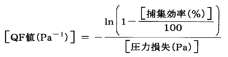
- the mixed fiber non-woven fabric of the present invention, QF value defined by the following equation is preferably at 0.10 Pa -1 or more, more preferably 0.15 Pa -1 or higher, 0.18Pa -1 or Is a more preferred embodiment. The larger the QF value, the same collection efficiency can be achieved with lower pressure loss.
- the mixed fiber nonwoven fabric of the present invention may be laminated with other sheets to form a laminated fiber nonwoven fabric.
- a non-woven fabric sheet and a sheet having higher rigidity than the laminated sheet to improve product strength, or to use in combination with a sheet having functionalities such as deodorization and antibacterial.
- the laminating method include a method of bonding two types of non-woven fabrics using an adhesive, and a method of laminating by a melt blow method on a non-woven fabric sheet produced by a production method other than the melt blow method.
- a method of bonding two kinds of nonwoven fabrics there are a method of spraying a moisture-curable urethane resin by a spray method, a method of spraying a thermoplastic resin and a heat-bonding fiber, and bonding them through a heat path.
- the main use of the mixed fiber nonwoven fabric of the present invention is a mixed fiber nonwoven fabric used for a filter, a laminating method that causes an increase in pressure loss is not preferable.
- the spray method using a moisture curable urethane resin is a preferable method because it can be bonded without pressing two nonwoven fabrics, and thus the increase in pressure loss at the time of bonding is small.
- a mixed fiber nonwoven fabric having low pressure loss and high collection efficiency can be obtained, and this mixed fiber nonwoven fabric can be suitably used as a filter medium, particularly for an air filter.
- the mixed fiber nonwoven fabric of the present invention can be suitably used as a filter medium.
- This filter medium is suitable for high-performance applications of air filters in general, especially air-conditioning filters, air purifier filters, and automobile cabin filters, but the application range is not limited thereto.
- volume ratio of fiber The volume ratio of the fiber composed of the polyolefin resin component A and the fiber composed of the polyolefin resin component B was calculated by the following formula using the obtained fiber diameter value.
- the volume is calculated on the assumption that the length of the fiber included in each fiber group is constant ( ⁇ ).
- the QF value that serves as an index of filtration performance is calculated by the following equation using the collection efficiency and pressure loss. The lower the pressure loss and the higher the collection efficiency, the higher the QF value, indicating better filtration performance.
- Collection efficiency and pressure loss Measurement samples of length ⁇ width 15 cm ⁇ 15 cm were collected at five places in the longitudinal direction of the mixed fiber nonwoven fabric, and each sample was measured with a collection efficiency measuring device shown in FIG.
- a dust storage box 2 is connected to an upstream side of a sample holder 1 for setting a measurement sample M, and a flow meter 3, a flow rate adjusting valve 4 and a blower 5 are connected to a downstream side.
- a particle counter 6 is used for the sample holder 1, and the number of dusts on the upstream side and the number of dusts on the downstream side of the measurement sample M can be measured via the switching cock 7.
- the sample holder 1 includes a pressure gauge 8 and can read a static pressure difference between the upstream and downstream of the measurement sample M.
- a 0.309 U 10% polystyrene solution (manufacturer: Nacalai Tesque) is diluted 200 times with distilled water and filled in the dust storage box 2.
- the measurement sample M is set in the sample holder 1, the air volume is adjusted by the flow rate adjusting valve 4 so that the filter passing speed is 4.5 m / min, and the dust concentration is 10,000 to 40,000 pieces / 2.83.
- ⁇ 10 ⁇ 4 m 3 (0.01 ft 3 ) is stabilized, and the number of dusts D upstream of the measurement sample M and the number of dusts d downstream of the measurement sample M are set to one by a particle counter 6 (manufactured by Rion, KC-01B).
- Collection efficiency (%) [1- (d / D)] ⁇ 100 However, d: Total number of downstream dust measured three times D: Total number of upstream dust measured three times.
- the pressure loss was obtained by reading the static pressure difference between the upstream and downstream of the sample M at the time of measuring the collection efficiency with the pressure gauge 8. The average value of the five measurement samples was taken as the final pressure loss.
- Example 1 As a polyolefin resin component A, 1 mass of “Kimasorb” (registered trademark) 944 (manufactured by BASF Japan Ltd.) is added to a polypropylene (PP) resin having an MFR of 860 g / 10 min at a temperature of 230 ° C. and a load of 21.18 N. % Polyolefin resin component B “Wintech” (registered trademark) WMG03 (propylene / ethylene random copolymer, MFR at 230 ° C.
- PP polypropylene
- melt blow nozzle for mixed fiber spinning having two extruders and a gear pump and two types of discharges a and b (a hole diameter: 0.25 mm, b hole diameter: 0.6 mm, a hole depth: 2.5 mm, b hole depth: 3.5 mm, a hole number: 95 holes, b hole number: 20 holes, base width 150 mm, aa hole Pitch: 1 mm, ab hole pitch: 2 mm, hole arrangement: 5 a holes are inserted between b holes and arranged in a line), compressed air generator and air heater, collection conveyor, and winder A melt blown nonwoven fabric was produced using an apparatus comprising:
- the resin pellets of the polyolefin resin component A and the resin pellets of the polyolefin resin component B are respectively charged and melted by heating at a temperature of 265 ° C., and the gear pump is connected to the polyolefin resin component A.
- the mass ratio (%) of the polyolefin resin component B is set to 6: 4, and the above polyolefin resin component A and polyolefin resin component B are respectively mixed with a hole and b of the melt blow nozzle for mixed fiber spinning. It led to the hole and discharged at a nozzle temperature of 265 ° C. with a single hole discharge amount of 0.15 g / min / hole and 0.48 g / min / hole, respectively.
- the discharged polymer was thinned with pressurized air at a pressure of 0.10 MPa and a temperature of 285 ° C., and sprayed onto a collecting conveyor installed at a distance of 20 cm from the die discharge hole to form a sheet.
- the collection conveyor speed was adjusted to obtain a mixed nonwoven fabric with a basis weight of 30 g / m 2 .
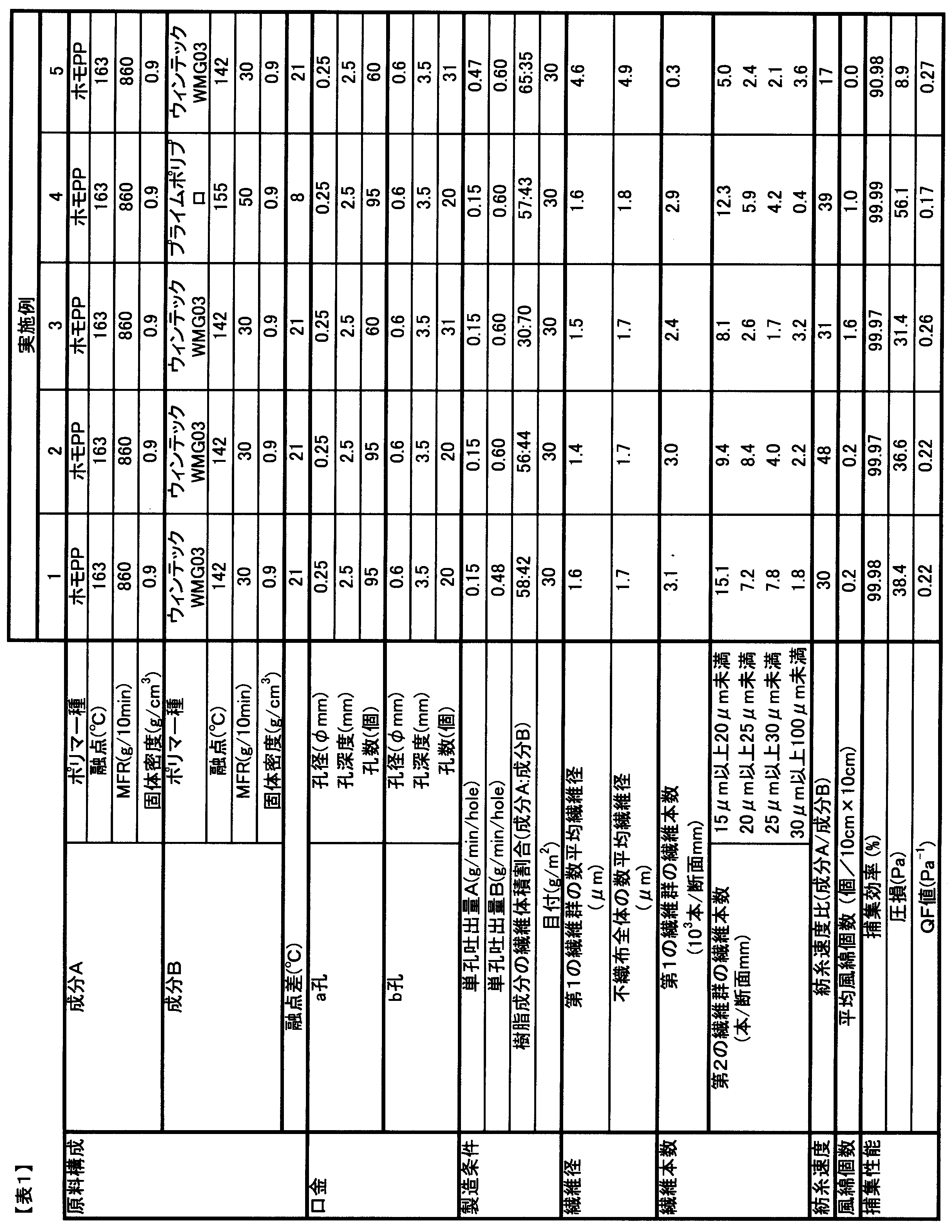
- the number average fiber diameter of the entire mixed nonwoven fabric was measured from the mixed nonwoven fabric obtained in Example 1, and is shown in Table 1. Moreover, the number of fibers per unit cross-sectional length of the entire mixed fiber nonwoven fabric was measured.
- Example 1 the mixed fiber nonwoven fabric obtained in Example 1 is heat-treated at a temperature between the melting points of the polyolefin resin component A and the polyolefin resin component B, thereby melting the fibers composed of the polyolefin resin component B. It was.
- the number average fiber diameter of this mixed fiber nonwoven fabric was measured, and the number average fiber diameter of the first fiber group was shown in Table 1.
- the fiber number of the 1st fiber group per unit cross-sectional length was measured.
- each fiber diameter section take the difference between the number of fibers per unit cross-sectional length of the whole mixed non-woven fabric before heat treatment and the number of fibers of the first fiber group per unit cross-sectional length after heat treatment, from the polyolefin resin component B Calculated as the number of fibers per unit cross-sectional length of the fibers, and the number of fibers per unit cross-sectional length of the second fiber group consisting of polyolefin resin component B and each fiber diameter of 15 to 100 ⁇ m. It was shown in Table 1 together with the volume ratio of the fibers composed of the resin based resin component A and the fibers composed of the polyolefin based resin component B.
- Example 1 the number of fluff contained in the nonwoven fabric surface 10 cm ⁇ 10 cm corresponding to the side opposite to the surface landed on the collecting conveyor was measured, and five measurement samples were measured.
- the number of cotton wool was calculated from the average value of the values shown in Table 1.
- Example 1 the mixed fiber nonwoven fabric obtained in Example 1 was impregnated with a mixed aqueous solution having a component weight ratio of pure water and isopropyl alcohol of 70:30, and then naturally dried to obtain an electret melt blown mixed fiber nonwoven fabric. Obtained.
- the characteristic values of this electret meltblown mixed nonwoven fabric were measured and are shown in Table 1.
- Example 2 The mass ratio (%) between the polyolefin resin component A and the polyolefin resin component B was 55:45, the single hole discharge rate of the hole b was 0.60 g / min, and the pressure of the pressurized air was 0.13 MPa. Except for the above, a mixed fiber nonwoven fabric was produced by the same method as in Example 1. With respect to the nonwoven fabric obtained in Example 2, various characteristic values were measured by the same method as in Example 1, and are shown in Table 1.
- Example 3 As a blended fiber spinning die, a die having a hole arrangement in which two a holes are inserted between b holes, the mass ratio (%) of the polyolefin resin component A to the polyolefin resin component B is 33:67, A nonwoven fabric was produced in the same manner as in Example 1 except that the single-hole discharge rate of a was 0.60 g / min / hole, and the pressure of the pressurized air was 0.19 MPa. With respect to the mixed fiber nonwoven fabric obtained in Example 3, various characteristic values were measured by the same method as in Example 1, and are shown in Table 1.
- Example 4 As the polyolefin resin component B, “Prime Polypro” (registered trademark) J229E manufactured by Prime Polymer Co., Ltd. (propylene / ethylene random copolymer, MFR at a temperature of 230 ° C. is 50 g / 10 min, melting point: 155 ° C.), The mass ratio (%) between the polyolefin resin component A and the resin component B is 54:46, the single hole discharge rate of the hole a is 0.15 g / min / hole, and the single hole discharge amount of the hole b is 0.60 g / The nonwoven fabric was manufactured by the same method as Example 3 except having set it as min and the pressure of pressurized air was 0.13 MPa. Various characteristic values of the mixed fiber nonwoven fabric obtained in Example 4 were measured by the same method as in Example 1, and are shown in Table 1.
- Example 5 The mass ratio (%) between the polyolefin resin component A and the polyolefin resin component B is 61:39, the single hole discharge rate of the hole a is 0.47 g / min / hole, and the single hole discharge amount of the hole b is 0.
- a mixed fiber nonwoven fabric was produced by the same method as in Example 3 except that the pressure was 60 g / min and the pressure of the pressurized air was 0.07 MPa. With respect to the nonwoven fabric obtained in Example 5, various characteristic values were measured by the same method as in Example 1, and are shown in Table 1.
- Polyolefin resin component B is polypropylene resin (melting point: 163 ° C.) having an MFR of 60 g / 10 min at a temperature of 230 ° C. and a 21.18 N load condition, “Kimasorb” (registered trademark) 944 (manufactured by BASF Japan Ltd.) 1% by mass of polyolefin resin component A and resin component B are mass ratio (%) of 43:57, single hole discharge rate of hole b is 0.90 g / min / hole, and extrusion A mixed fiber nonwoven fabric was produced by the same method as in Example 1 except that the machine temperature was 280 ° C, the nozzle temperature was 280 ° C, the pressurized air pressure was 0.05 MPa, and the pressurized air temperature was 300 ° C. .
- the cross section of the nonwoven fabric obtained in Comparative Example 1 was observed with a scanning electron microscope.
- the fiber diameter of the ejection fiber group from the hole a was less than 10 ⁇ m
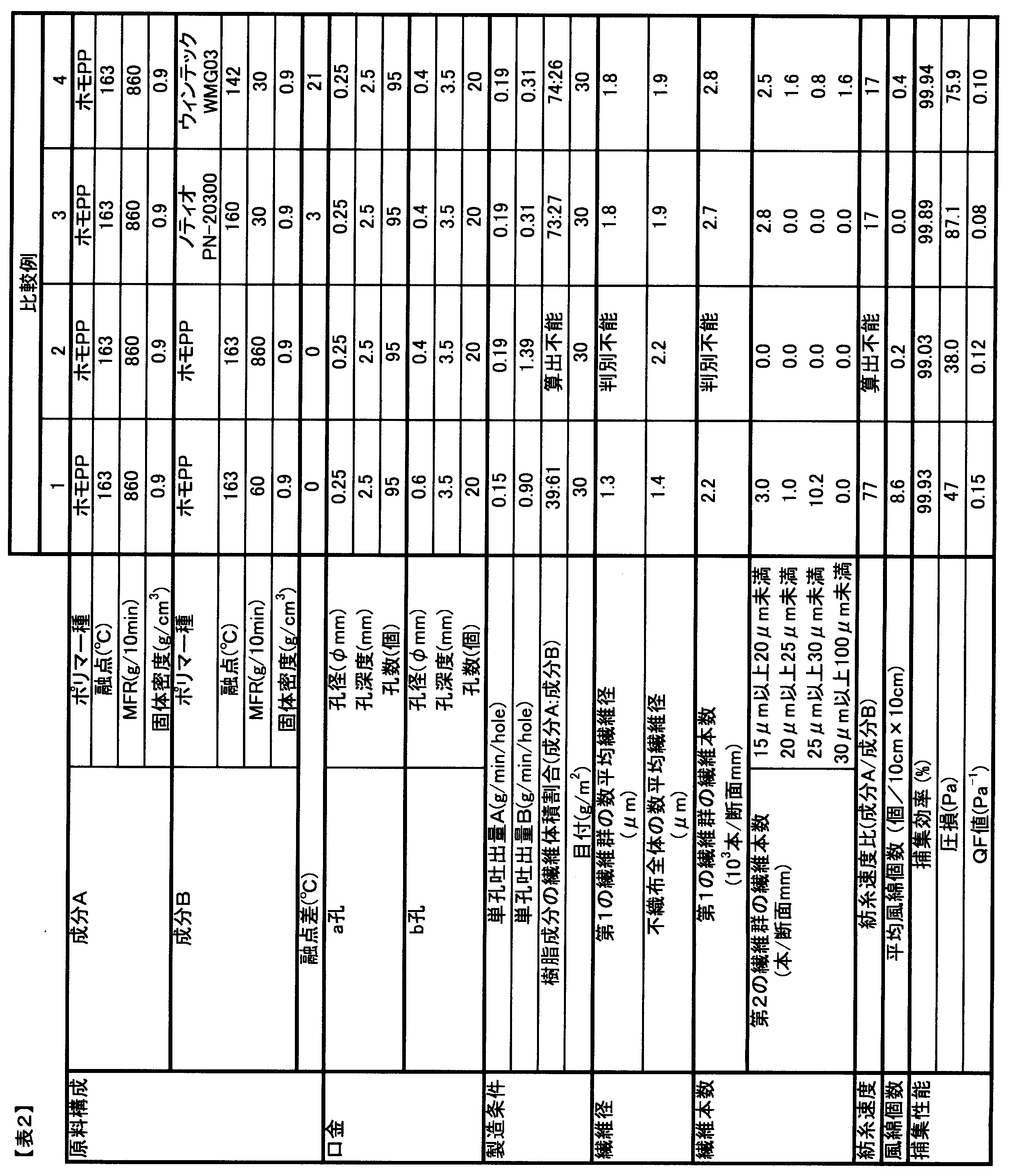
- the fiber diameter of the ejection fiber group from the hole b was 10 ⁇ m. It was confirmed that the fiber diameter distribution was clearly different from the above. Based on this, the number average fiber diameter and the number of fibers were measured for a fiber group having a fiber diameter of less than 10 ⁇ m and a fiber group having a fiber diameter of 10 ⁇ m or more. Furthermore, after the mixed fiber nonwoven fabric obtained in Comparative Example 1 was electret-treated by the same method as in Example 1, characteristic values were measured and shown in Table 2.
- the cross section of the nonwoven fabric obtained in Comparative Example 2 was observed with a scanning electron microscope.
- the fiber diameters of the ejected fiber from the hole a and the ejected fiber from the hole b were close to each other, and it was impossible to determine which fiber was from the observation photograph. For this reason, the number average fiber diameters of the two types of fibers could not be measured respectively. Further, no fiber having a fiber diameter exceeding 15 ⁇ m was observed.
- the mixed fiber nonwoven fabric obtained in Comparative Example 2 was electret-treated by the same method as in Example 1, and the characteristic values were measured and shown in Table 2.
- Example 1 a mixed fiber obtained by adjusting two types of raw materials, discharge amount, pressurized air pressure, nozzle temperature, and the like using a mixed fiber melt blow spinning facility.
- the non-woven fabric contained a first group of fibers made of polypropylene resin and having a number average fiber diameter of 1.6 ⁇ m as the first group of fibers. Further, this mixed fiber non-woven fabric is composed of a polyolefin resin having a melting point of 21 ° C. lower than that of the polypropylene resin as a second fiber group in the fiber comprising the polypropylene resin component B, and the single fiber diameter is 15 to 100 ⁇ m.
- the mixed fiber nonwoven fabric exhibited a high collection efficiency exceeding 99.97% while being subjected to a charging treatment with low pressure loss.
- Example 3 even when the composition of the spinneret and the composition ratio of the polymer were changed, high collection efficiency was exhibited with low pressure loss. In Example 4, even when the type of polymer used was changed, a high collection efficiency was exhibited with a low pressure loss.
- These mixed fiber nonwoven fabrics exhibiting a high QF value can be suitably used as filter media for HEPA filters. Further, in Example 5, a mixed fiber nonwoven fabric having an extremely high QF value as an index of filter performance was obtained by changing conditions such as the composition of the spinneret and the composition ratio of the polymer.
- the nonwoven fabric shown in Comparative Example 1 has a fiber group composed of fibers having a fiber diameter of 15 ⁇ m to 100 ⁇ m and 5 times larger than the number average fiber diameter of the polypropylene fiber group. It did not contain any component having a melting point 5 to 40 ° C. lower than that of polypropylene. For this reason, compared with the mixed fiber nonwoven fabric shown by Example 2 which consists of a structure with a near fiber diameter, the number of the fluff increased and it became the low collection efficiency.
- the mixed fiber nonwoven fabric shown in Comparative Example 2 did not contain fibers having a fiber diameter of 15 ⁇ m or more and 100 ⁇ m or less in the nonwoven fabric, and did not contain a resin component having a melting point 5 to 40 ° C. lower than that of polypropylene. For this reason, sufficient collection efficiency could not be achieved.
- the mixed nonwoven fabric shown in Comparative Example 3 did not contain a predetermined amount of fibers having a fiber diameter of 15 ⁇ m or more and 100 ⁇ m or less in the nonwoven fabric. Further, it did not contain a resin component having a melting point 5 to 40 ° C. lower than that of polypropylene. For this reason, sufficient collection efficiency could not be achieved, and high pressure loss was exhibited.
- the mixed nonwoven fabric shown in Comparative Example 4 did not contain a predetermined amount of fibers having a fiber diameter of 15 ⁇ m or more and 100 ⁇ m or less in the nonwoven fabric. For this reason, sufficient collection efficiency could not be achieved, and high pressure loss was exhibited.
- the fiber diameters of the fine fibers and the thick fibers and the components of the respective fibers are specified so that the pressure loss is low. Furthermore, a mixed fiber nonwoven fabric excellent in collection efficiency could be obtained.
Landscapes
- Engineering & Computer Science (AREA)
- Mechanical Engineering (AREA)
- Textile Engineering (AREA)
- Chemical & Material Sciences (AREA)
- Chemical Kinetics & Catalysis (AREA)
- Nonwoven Fabrics (AREA)
- Filtering Materials (AREA)
Abstract
Description


タテ×ヨコ=15cm×15cmの不混繊織布の質量を3点測定し、それぞれ得られた値を1m2当たりの値に換算し、その平均値を取って不織布の目付(g/m2)とした。
混繊不織布の任意の場所から、タテ×ヨコ=3mm×3mmの測定サンプルを12個採取し、走査型電子顕微鏡で倍率を調節して、採取したサンプルから繊維表面写真を各1枚ずつ、計12枚を撮影した。倍率は、200~3000倍とした。写真の中の繊維直径がはっきり確認できる繊維について、すべて繊維径を測定した。各繊維径は、有効数字0.1μmの測定精度にて行った。この値を合計し、測定した繊維本数で割った値を数平均繊維径とした。数平均繊維径は、1.0μm以上は有効数字2桁とし、1.0μm未満は有効数字1桁として算出した。
混繊不織布の任意の場所から、縦×横=20mm×5mmの混繊不織布片12個を採取し、片にエポキシ樹脂を含浸し固化させた。この混繊不織布を片刃カミソリによって切断し、縦×横=1mm×5mmの断片を得た。この断片の切断面について、走査型電子顕微鏡によって撮影し、計12枚の混繊不織布断面写真を得た。倍率は200倍~1000倍とし、写真の中の繊維断面形状がはっきり確認できるものについては、すべて計数した。
ポリオレフィン系樹脂成分Aからなる繊維とポリオレフィン系樹脂成分Bからなる繊維の体積割合は、得られた繊維径の値を用い、次式により算出した。ここで、各繊維群に含まれる繊維の長さは一定(α)と仮定して、体積を算出している。
・各繊維の体積 :β=π(繊維径/2)2×α
・ポリオレフィン系樹脂成分Aからなる繊維の体積
γ(A)=ポリオレフィン系樹脂成分Aからなる繊維のβの総和
・ポリオレフィン系樹脂成分Bからなる繊維の体積
γ(B)=ポリオレフィン系樹脂成分Aからなる繊維のβの総和
・ポリオレフィン系樹脂成分Aからなる繊維の体積割合(vol%)
=γ(A)/[γ(A)+γ(B)]
・ポリオレフィン系樹脂成分Bからなる繊維の体積割合(vol%)
=γ(B)/[γ(A)+γ(B)]
(5)QF値
濾過性能の指標となるQF値は、前記の捕集効率および圧損を用いて、次の式により計算される。低圧損かつ高捕集効率であるほどQF値は高くなり、濾過性能が良好であることを示す。
混繊不織布の縦方向5カ所でタテ×ヨコ=15cm×15cmの測定用サンプルを採取し、それぞれのサンプルについて、図1に示す捕集効率測定装置で測定した。この捕集効率測定装置は、測定サンプルMをセットするサンプルホルダー1の上流側にダスト収納箱2を連結し、下流側に流量計3、流量調整バルブ4、およびブロワ5が連結されている。また、サンプルホルダー1にパーティクルカウンター6を使用しており、切替コック7を介して、測定サンプルMの上流側のダスト個数と下流側のダスト個数をそれぞれ測定することができる。さらに、サンプルホルダー1は圧力計8を備え、測定サンプルMの上流と下流での静圧差を読み取ることができる。
・捕集効率(%)=〔1-(d/D)〕×100
ただし、
d:下流ダストの3回測定トータル個数
D:上流のダストの3回測定トータル個数
である。
ポリオレフィン系樹脂成分Aとして、温度230℃で21.18N負荷時におけるMFRが860g/10minのポリプロピレン(PP)樹脂に、“キマソーブ”(登録商標)944(BASF・ジャパン(株)製)を1質量%添加したものを使用し、ポリオレフィン系樹脂成分Bとして、日本ポリプロ(株)製“ウィンテック”(登録商標)WMG03(プロピレン・エチレンランダム共重合体・温度230℃におけるMFRが30g/10min、融点142℃)を使用し、2機の押出機およびギヤポンプ、2種類の吐出a、bを備えた混繊紡糸用メルトブロー口金(a孔径:0.25mm、b孔径:0.6mm、a孔深度:2.5mm、b孔深度:3.5mm、a孔数:95ホール、b孔数:20ホール、口金幅150mm、a-a孔ピッチ:1mm、a-b孔ピッチ:2mm、孔配列:b孔の間に5つのa孔を挿入して一列に配列)、圧縮空気発生装置および空気加熱機、捕集コンベア、および巻取機からなる装置を用いて、メルトブロー不織布の製造を行った。
ポリオレフィン系樹脂成分Aとポリオレフィン系樹脂成分Bの質量比(%)を55:45とし、孔bの単孔吐出量を0.60g/minとし、加圧空気の圧力を0.13MPaとしたこと以外は、実施例1と同じ方法によって混繊不織布を製造した。実施例2で得られた不織布について、実施例1と同じ方法で各種特性値を計測し、表1に示した。
混繊紡糸用口金として、b孔間に2つのa孔が挿入された孔配列の口金を用い、ポリオレフィン系樹脂成分Aとポリオレフィン系樹脂成分Bの質量比(%)を33:67とし、孔aの単孔吐出量を0.60g/min/holeとし、加圧空気の圧力を0.19MPaとしたこと以外は、実施例1と同じ方法によって不織布を製造した。実施例3で得られた混繊不織布について、実施例1と同じ方法で各種特性値を計測し、表1に示した。
ポリオレフィン系樹脂成分Bとして、プライムポリマー(株)製“プライムポリプロ”(登録商標)J229E(プロピレン・エチレンランダム共重合体・温度230℃におけるMFRが50g/10min、融点:155℃)を使用し、ポリオレフィン系樹脂成分Aと樹脂成分Bの質量比(%)を54:46とし、孔aの単孔吐出量を0.15g/min/holeとし、孔bの単孔吐出量を0.60g/minとし、加圧空気の圧力を0.13MPaとしたこと以外は、実施例3と同じ方法によって不織布を製造した。実施例4で得られた混繊不織布について、実施例1と同じ方法で各種特性値を計測し、表1に示した。
ポリオレフィン系樹脂成分Aとポリオレフィン系樹脂成分Bの質量比(%)を61:39とし、孔aの単孔吐出量を0.47g/min/holeとし、孔bの単孔吐出量を0.60g/minとし、加圧空気の圧力を0.07MPaとしたこと以外は、実施例3と同じ方法によって混繊不織布を製造した。実施例5で得られた不織布について、実施例1と同じ方法で各種特性値を計測し、表1に示した。
ポリオレフィン系樹脂成分Bとして、温度230℃、21.18N荷重条件におけるMFRが60g/10minであるポリプロピレン樹脂(融点163℃)に、“キマソーブ”(登録商標)944(BASF・ジャパン(株)製)を1質量%添加したものを使用し、ポリオレフィン系樹脂成分Aと樹脂成分Bの質量比(%)を43:57とし、孔bの単孔吐出量を0.90g/min/holeとし、押出機温度を280℃とし、ノズル温度を280℃とし、加圧空気圧力を0.05MPaとし、加圧空気温度を300℃としたこと以外は、実施例1と同じ方法によって混繊不織布を製造した。
混繊紡糸用メルトブロー口金のb孔径を0.4mmとし、ポリオレフィン系樹脂成分Bとして温度230℃、21.18N荷重条件におけるMFRが860g/10minであるポリプロピレン樹脂(融点163℃)に“キマソーブ”(登録商標)944(BASF・ジャパン(株)製)を1質量%添加したものを使用し、ポリオレフィン系樹脂成分Aとポリオレフィン系樹脂成分Bの質量比(%)を40:60とし、孔aの単孔吐出量を0.19g/min/hole、bの単孔吐出量を1.39g/min/hole、押出機温度を265℃とし、ノズル温度を255℃とし、加圧空気圧力を0.15MPaとし、加圧空気温度を265℃としたこと以外は、実施例1と同じ方法によって混繊不織布を製造した。
混繊紡糸用メルトブロー口金のb孔径を0.4mmとし、ポリオレフィン系樹脂成分Bとして三井化学(株)製“ノティオ”(登録商標)PN-20300(ポリオレフィン共重合エラストマー・温度230℃におけるMFRが30g/10min、融点160℃)を使用し、ポリオレフィン系樹脂成分Aと成分Bの質量比(%)を75:25とし、孔aの単孔吐出量を0.19g/min/hole、bの単孔吐出量を0.31g/min/holeとしたこと以外は、実施例1と同じ方法によって混繊不織布を製造した。比較例3で得られた混繊不織布について、実施例1と同じ方法で各種特性値を計測し、表2に示した。
混繊紡糸用メルトブロー口金のb孔径を0.4mmとし、ポリオレフィン系樹脂成分Aとポリオレフィン系樹脂成分Bの質量比(%)を75:25とし、孔aの単孔吐出量を0.19g/min/hole、bの単孔吐出量を0.31g/min/holeとしたこと以外は、実施例1と同じ方法によって混繊不織布を製造した。比較例4で得られた混繊不織布について、実施例1と同じ方法で各種特性値を計測し、表2に示した。
2:ダスト収納箱
3:流量計
4:流量調整バルブ
5:ブロワ
6:パーティクルカウンター
7:切替コック
8:圧力計
M:測定サンプル
Claims (10)
- 少なくとも2種類のポリオレフィン系樹脂成分Aからなる繊維とポリオレフィン系樹脂成分Bからなる繊維を含む繊維群で構成されてなる混繊不織布であって、前記ポリオレフィン系樹脂成分Aからなる繊維を第1の繊維群と定義するとき、前記第1の繊維群の数平均繊維径が0.3~7.0μmであり、前記ポリオレフィン系樹脂成分Bからなる繊維のうち、前記第1の繊維群の数平均繊維径よりも各々の繊維径が5倍以上大きく、かつ各々の繊維径が15~100μmである繊維からなる群を第2の繊維群として定義するとき、前記第2の繊維群が、繊維の形態を保持した状態で混繊不織布の断面中に、断面長1mmあたり7.0本以上含まれており、かつ、前記ポリオレフィン系樹脂成分Bの融点が前記ポリオレフィン系樹脂成分Aよりも5~40℃低く、前記混繊不織布全体の繊維の数平均繊維径が0.3~10μmであることを特徴とする混繊不織布。
- 第1の繊維群の本数Xと第2の繊維群の本数Yの比X/Yが、50~5000の範囲であることを特徴とする請求項1記載の混繊不織布である。
- 混繊メルトブロー法によって製造されていることを特徴とする請求項1または2記載の混繊不織布。
- ポリオレフィン系樹脂成分Aが、ポリプロピレンホモポリマーであることを特徴とする請求項1から3のいずれかに記載の混繊不織布。
- ポリオレフィン系樹脂成分Bが、プロピレン-エチレン共重合体であることを特徴とする請求項1から4のいずれかに記載の混繊不織布。
- 混繊不織布に含まれるポリオレフィン系樹脂成分Aからなる繊維とポリオレフィン系樹脂成分Bからなる繊維の体積割合A:Bが、20:80~90:10の範囲にあることを特徴とする請求項1から5のいずれかに記載の混繊不織布。
- 帯電処理されていることを特徴とする請求項1から6のいずれかに記載の混繊不織布。
- 請求項1から7のいずれかに記載の混繊不織布を少なくとも1層含有することを特徴とする積層シート。
- 請求項1から8のいずれかに記載の混繊不織布または請求項8に記載の積層シートを含むことを特徴とするフィルター。
- 2種類の異なるポリオレフィン系樹脂成分Aおよびポリオレフィン系樹脂成分Bを、同一ダイに設けられた別々の吐出孔から吐出し、混繊不織布を製造する方法であって、前記ポリオレフィン系樹脂成分Aの融点が、前記ポリオレフィン系樹脂成分Bの融点よりも5~40℃高く、かつ、前記ポリオレフィン系樹脂成分Aのメルトフローレートが、前記ポリオレフィン系樹脂成分Bのメルトフローレートよりも5~100倍高く、前記ポリオレフィン系樹脂成分Aからなる繊維の見かけの紡糸速度が、前記ポリオレフィン系樹脂成分Bからなる繊維の見かけの紡糸速度に比べ、20~500倍早いことを特徴とする混繊不織布の製造方法。
Priority Applications (5)
| Application Number | Priority Date | Filing Date | Title |
|---|---|---|---|
| CN201480020536.8A CN105074075B (zh) | 2013-04-11 | 2014-04-03 | 混纺无纺布及其制造方法 |
| EP14783202.6A EP2985377B1 (en) | 2013-04-11 | 2014-04-03 | Mixed-fiber nonwoven fabric and method for manufacturing same |
| US14/783,485 US20160074790A1 (en) | 2013-04-11 | 2014-04-03 | Mixed fiber nonwoven fabric and a production method therefor (as amended) |
| JP2015511232A JP6390612B2 (ja) | 2013-04-11 | 2014-04-03 | 混繊不織布およびその製造方法 |
| KR1020157025955A KR102116776B1 (ko) | 2013-04-11 | 2014-04-03 | 혼섬 부직포 및 그 제조 방법 |
Applications Claiming Priority (2)
| Application Number | Priority Date | Filing Date | Title |
|---|---|---|---|
| JP2013082892 | 2013-04-11 | ||
| JP2013-082892 | 2013-04-11 |
Publications (1)
| Publication Number | Publication Date |
|---|---|
| WO2014168066A1 true WO2014168066A1 (ja) | 2014-10-16 |
Family
ID=51689476
Family Applications (1)
| Application Number | Title | Priority Date | Filing Date |
|---|---|---|---|
| PCT/JP2014/059800 Ceased WO2014168066A1 (ja) | 2013-04-11 | 2014-04-03 | 混繊不織布およびその製造方法 |
Country Status (7)
| Country | Link |
|---|---|
| US (1) | US20160074790A1 (ja) |
| EP (1) | EP2985377B1 (ja) |
| JP (1) | JP6390612B2 (ja) |
| KR (1) | KR102116776B1 (ja) |
| CN (1) | CN105074075B (ja) |
| TW (1) | TW201444691A (ja) |
| WO (1) | WO2014168066A1 (ja) |
Cited By (3)
| Publication number | Priority date | Publication date | Assignee | Title |
|---|---|---|---|---|
| JP2015161041A (ja) * | 2014-02-27 | 2015-09-07 | 東レ株式会社 | 混繊不織布 |
| WO2019082887A1 (ja) * | 2017-10-25 | 2019-05-02 | Jnc株式会社 | 混繊不織布、積層体、フィルター用濾材及びこれらの製造方法 |
| JPWO2022250057A1 (ja) * | 2021-05-26 | 2022-12-01 |
Families Citing this family (9)
| Publication number | Priority date | Publication date | Assignee | Title |
|---|---|---|---|---|
| WO2016017484A1 (ja) * | 2014-07-30 | 2016-02-04 | 日本バイリーン株式会社 | 濾過材、それを用いたフィルタエレメント、及び濾過材の製造方法 |
| JP7248401B2 (ja) * | 2018-09-26 | 2023-03-29 | Jnc株式会社 | デプスフィルター |
| JP7591505B2 (ja) * | 2019-08-30 | 2024-11-28 | 株式会社ダイセル | 繊維物品 |
| KR20220116146A (ko) * | 2019-10-08 | 2022-08-22 | 도날드슨 컴파니, 인코포레이티드 | 혼합된 직경 미세 섬유를 포함하는 필터 매체 층 |
| CN116194187A (zh) | 2020-04-02 | 2023-05-30 | 唐纳森公司 | 过滤介质、复合材料以及使用该过滤介质的面罩系统 |
| EP4126295A1 (en) | 2020-04-03 | 2023-02-08 | Donaldson Company, Inc. | Filtration media |
| WO2021256445A1 (ja) | 2020-06-19 | 2021-12-23 | 花王株式会社 | 繊維シート、電界紡糸装置及び繊維シートの製造方法 |
| DE102020116689A1 (de) | 2020-06-24 | 2021-12-30 | Thüringisches Institut für Textil- und Kunststoff-Forschung Rudolstadt e.V. | Melaminharz-Filtervlies |
| KR20260040442A (ko) * | 2023-07-20 | 2026-03-24 | 다우 글로벌 테크놀로지스 엘엘씨 | 섬유 혼합물을 포함하는 스펀본드 부직포 |
Citations (19)
| Publication number | Priority date | Publication date | Assignee | Title |
|---|---|---|---|---|
| US3981650A (en) | 1975-01-16 | 1976-09-21 | Beloit Corporation | Melt blowing intermixed filaments of two different polymers |
| JPS63280408A (ja) | 1987-05-12 | 1988-11-17 | Toray Ind Inc | 耐熱性エレクトレット材料 |
| JPH02104765A (ja) | 1988-10-11 | 1990-04-17 | Toray Ind Inc | エレクトレット不織布の製造方法 |
| JPH02112460A (ja) * | 1988-10-17 | 1990-04-25 | Asahi Chem Ind Co Ltd | 高強力シート状物 |
| JPH0693551A (ja) | 1991-11-25 | 1994-04-05 | Kanebo Ltd | 伸縮性繊維シート及びその製造方法 |
| JPH0782649A (ja) | 1993-07-16 | 1995-03-28 | Chisso Corp | 極細混合繊維製品及びその製造方法 |
| JPH0813309A (ja) | 1994-07-01 | 1996-01-16 | Tonen Chem Corp | メルトブロー不織布及びその製造方法 |
| JPH09501604A (ja) | 1993-08-17 | 1997-02-18 | ミネソタ・マイニング・アンド・マニュファクチュアリング・カンパニー | エレクトレット濾過材の荷電方法 |
| JP2770379B2 (ja) * | 1989-03-07 | 1998-07-02 | 東レ株式会社 | 不織布 |
| US5783011A (en) | 1995-05-02 | 1998-07-21 | Memtec America Corporation | Method of making filtration media having integrally co-located support and filtration fibers |
| JPH11131353A (ja) | 1997-10-29 | 1999-05-18 | Tonen Tapirusu Kk | メルトブロー不織布およびメルトブロー不織布用ノズルピース |
| JP2002201560A (ja) | 2000-12-28 | 2002-07-19 | Mitsui Chemicals Inc | 極細繊維メルトブロー不織布用ポリプロピレン及びそれからなる不織布並びにエアフィルター |
| JP2002249978A (ja) | 2000-11-28 | 2002-09-06 | Toray Ind Inc | エレクトレット加工品の製造方法 |
| JP2005171456A (ja) | 2003-12-15 | 2005-06-30 | Chisso Corp | 伸縮性不織布およびそれを用いた繊維製品 |
| JP2006112025A (ja) | 2002-08-08 | 2006-04-27 | Chisso Corp | 弾性不織布及びこれを用いた繊維製品 |
| JP2009545682A (ja) | 2006-07-31 | 2009-12-24 | スリーエム イノベイティブ プロパティズ カンパニー | モノコンポーネント単層メルトブローンウェブ及びメルトブローイング装置 |
| JP2010511488A (ja) | 2006-07-31 | 2010-04-15 | スリーエム イノベイティブ プロパティズ カンパニー | 成形濾過物品を作製する方法 |
| JP2011168903A (ja) | 2010-02-17 | 2011-09-01 | Kasen Nozuru Seisakusho:Kk | 不織布製造装置及び不織布製造方法 |
| JP2013177703A (ja) * | 2012-02-28 | 2013-09-09 | Toray Ind Inc | 混繊不織布 |
Family Cites Families (18)
| Publication number | Priority date | Publication date | Assignee | Title |
|---|---|---|---|---|
| US4405342A (en) * | 1982-02-23 | 1983-09-20 | Werner Bergman | Electric filter with movable belt electrode |
| US5019311A (en) * | 1989-02-23 | 1991-05-28 | Koslow Technologies Corporation | Process for the production of materials characterized by a continuous web matrix or force point bonding |
| US5227107A (en) * | 1990-08-07 | 1993-07-13 | Kimberly-Clark Corporation | Process and apparatus for forming nonwovens within a forming chamber |
| DE69407224T2 (de) * | 1993-07-16 | 1998-04-30 | Chisso Corp | Mikrofeinfaserprodukt und Verfahren zu seiner Herstellung |
| US5509430A (en) * | 1993-12-14 | 1996-04-23 | American Filtrona Corporation | Bicomponent fibers and tobacco smoke filters formed therefrom |
| US6267252B1 (en) * | 1999-12-08 | 2001-07-31 | Kimberly-Clark Worldwide, Inc. | Fine particle filtration medium including an airlaid composite |
| US20030176135A1 (en) * | 2002-03-15 | 2003-09-18 | Wenstrup Dave E. | Method for producing a spun-bonded nonwoven web with improved abrasion resistance |
| US6827764B2 (en) * | 2002-07-25 | 2004-12-07 | 3M Innovative Properties Company | Molded filter element that contains thermally bonded staple fibers and electrically-charged microfibers |
| US20070074628A1 (en) * | 2005-09-30 | 2007-04-05 | Jones David C | Coalescing filtration medium and process |
| DE102006014236A1 (de) * | 2006-03-28 | 2007-10-04 | Irema-Filter Gmbh | Plissierbares Vliesmaterial und Verfahren und Vorrichtung zur Herstellung derselben |
| US7754041B2 (en) * | 2006-07-31 | 2010-07-13 | 3M Innovative Properties Company | Pleated filter with bimodal monolayer monocomponent media |
| JP4944540B2 (ja) * | 2006-08-17 | 2012-06-06 | 日本バイリーン株式会社 | フィルタエレメント、その製造方法、並びに使用方法 |
| US20080315454A1 (en) * | 2007-06-22 | 2008-12-25 | 3M Innovative Properties Company | Method of making meltblown fiber web with staple fibers |
| EP2264099A1 (en) * | 2009-05-21 | 2010-12-22 | Basell Poliolefine Italia S.R.L. | Propylene polymer compositions |
| WO2010149693A1 (en) * | 2009-06-25 | 2010-12-29 | Nv Bekaert Sa | A diesel soot particulate filter cartridge |
| US20130122771A1 (en) * | 2010-07-29 | 2013-05-16 | Mitsui Chemicals, Inc. | Non-woven fiber fabric, and production method and production device therefor |
| JP2013540904A (ja) * | 2010-08-23 | 2013-11-07 | ファイバーウェブ コロビン ゲーエムベーハー | エレクトレット特性を有する不織ウェブ及び繊維、その製造方法並びにその使用 |
| WO2012174567A2 (en) * | 2011-06-17 | 2012-12-20 | Berry Plastics Corporation | Process for forming an insulated container having artwork |
-
2014
- 2014-04-03 CN CN201480020536.8A patent/CN105074075B/zh not_active Expired - Fee Related
- 2014-04-03 WO PCT/JP2014/059800 patent/WO2014168066A1/ja not_active Ceased
- 2014-04-03 TW TW103112428A patent/TW201444691A/zh unknown
- 2014-04-03 US US14/783,485 patent/US20160074790A1/en not_active Abandoned
- 2014-04-03 EP EP14783202.6A patent/EP2985377B1/en active Active
- 2014-04-03 JP JP2015511232A patent/JP6390612B2/ja not_active Expired - Fee Related
- 2014-04-03 KR KR1020157025955A patent/KR102116776B1/ko not_active Expired - Fee Related
Patent Citations (19)
| Publication number | Priority date | Publication date | Assignee | Title |
|---|---|---|---|---|
| US3981650A (en) | 1975-01-16 | 1976-09-21 | Beloit Corporation | Melt blowing intermixed filaments of two different polymers |
| JPS63280408A (ja) | 1987-05-12 | 1988-11-17 | Toray Ind Inc | 耐熱性エレクトレット材料 |
| JPH02104765A (ja) | 1988-10-11 | 1990-04-17 | Toray Ind Inc | エレクトレット不織布の製造方法 |
| JPH02112460A (ja) * | 1988-10-17 | 1990-04-25 | Asahi Chem Ind Co Ltd | 高強力シート状物 |
| JP2770379B2 (ja) * | 1989-03-07 | 1998-07-02 | 東レ株式会社 | 不織布 |
| JPH0693551A (ja) | 1991-11-25 | 1994-04-05 | Kanebo Ltd | 伸縮性繊維シート及びその製造方法 |
| JPH0782649A (ja) | 1993-07-16 | 1995-03-28 | Chisso Corp | 極細混合繊維製品及びその製造方法 |
| JPH09501604A (ja) | 1993-08-17 | 1997-02-18 | ミネソタ・マイニング・アンド・マニュファクチュアリング・カンパニー | エレクトレット濾過材の荷電方法 |
| JPH0813309A (ja) | 1994-07-01 | 1996-01-16 | Tonen Chem Corp | メルトブロー不織布及びその製造方法 |
| US5783011A (en) | 1995-05-02 | 1998-07-21 | Memtec America Corporation | Method of making filtration media having integrally co-located support and filtration fibers |
| JPH11131353A (ja) | 1997-10-29 | 1999-05-18 | Tonen Tapirusu Kk | メルトブロー不織布およびメルトブロー不織布用ノズルピース |
| JP2002249978A (ja) | 2000-11-28 | 2002-09-06 | Toray Ind Inc | エレクトレット加工品の製造方法 |
| JP2002201560A (ja) | 2000-12-28 | 2002-07-19 | Mitsui Chemicals Inc | 極細繊維メルトブロー不織布用ポリプロピレン及びそれからなる不織布並びにエアフィルター |
| JP2006112025A (ja) | 2002-08-08 | 2006-04-27 | Chisso Corp | 弾性不織布及びこれを用いた繊維製品 |
| JP2005171456A (ja) | 2003-12-15 | 2005-06-30 | Chisso Corp | 伸縮性不織布およびそれを用いた繊維製品 |
| JP2009545682A (ja) | 2006-07-31 | 2009-12-24 | スリーエム イノベイティブ プロパティズ カンパニー | モノコンポーネント単層メルトブローンウェブ及びメルトブローイング装置 |
| JP2010511488A (ja) | 2006-07-31 | 2010-04-15 | スリーエム イノベイティブ プロパティズ カンパニー | 成形濾過物品を作製する方法 |
| JP2011168903A (ja) | 2010-02-17 | 2011-09-01 | Kasen Nozuru Seisakusho:Kk | 不織布製造装置及び不織布製造方法 |
| JP2013177703A (ja) * | 2012-02-28 | 2013-09-09 | Toray Ind Inc | 混繊不織布 |
Non-Patent Citations (1)
| Title |
|---|
| See also references of EP2985377A4 |
Cited By (8)
| Publication number | Priority date | Publication date | Assignee | Title |
|---|---|---|---|---|
| JP2015161041A (ja) * | 2014-02-27 | 2015-09-07 | 東レ株式会社 | 混繊不織布 |
| WO2019082887A1 (ja) * | 2017-10-25 | 2019-05-02 | Jnc株式会社 | 混繊不織布、積層体、フィルター用濾材及びこれらの製造方法 |
| US12157077B2 (en) | 2017-10-25 | 2024-12-03 | Jnc Corporation | Combined fiber nonwoven fabric, laminate, filtration medium for filter and method thereof |
| JPWO2022250057A1 (ja) * | 2021-05-26 | 2022-12-01 | ||
| WO2022250057A1 (ja) * | 2021-05-26 | 2022-12-01 | タピルス株式会社 | メルトブロー不織布及びこれを備えたフィルタ |
| KR20230028580A (ko) * | 2021-05-26 | 2023-02-28 | 타피러스 컴퍼니 리미티드 | 멜트블로우 부직포 및 이를 포함하는 필터 |
| JP7333119B2 (ja) | 2021-05-26 | 2023-08-24 | タピルス株式会社 | メルトブロー不織布及びこれを備えたフィルタ |
| KR102574822B1 (ko) | 2021-05-26 | 2023-09-04 | 타피러스 컴퍼니 리미티드 | 멜트블로우 부직포 및 이를 포함하는 필터 |
Also Published As
| Publication number | Publication date |
|---|---|
| TW201444691A (zh) | 2014-12-01 |
| KR20150140655A (ko) | 2015-12-16 |
| US20160074790A1 (en) | 2016-03-17 |
| CN105074075A (zh) | 2015-11-18 |
| EP2985377A1 (en) | 2016-02-17 |
| CN105074075B (zh) | 2019-11-05 |
| JP6390612B2 (ja) | 2018-09-19 |
| EP2985377A4 (en) | 2016-12-21 |
| KR102116776B1 (ko) | 2020-05-29 |
| JPWO2014168066A1 (ja) | 2017-02-16 |
| EP2985377B1 (en) | 2020-01-01 |
Similar Documents
| Publication | Publication Date | Title |
|---|---|---|
| JP6390612B2 (ja) | 混繊不織布およびその製造方法 | |
| JP6007899B2 (ja) | 混繊不織布と積層シート及びフィルター並びに混繊不織布の製造方法 | |
| US9180392B2 (en) | Mixed-fiber nonwoven fabric and filter medium using the same | |
| US9662601B2 (en) | Blended filament nonwoven fabric | |
| JP5205650B2 (ja) | 積層体およびその製造方法 | |
| JP2013177703A (ja) | 混繊不織布 | |
| KR101395450B1 (ko) | 주름잡을 수 있는 부직 재료 및 이를 제조하기 위한 방법 및 장치 | |
| JP6427922B2 (ja) | 混繊不織布 | |
| JP6256100B2 (ja) | 混繊メルトブロー不織布 | |
| JP2020196974A (ja) | メルトブロー不織布製造用口金ならびにメルトブロー不織布の製造装置および製造方法 | |
| WO2023210759A1 (ja) | エレクトレット及びエレクトレットフィルター | |
| CN110856780A (zh) | 一种空气过滤介质及空气过滤器 | |
| JP2023115977A (ja) | エレクトレット繊維シートおよびエレクトレット繊維シートの製造方法 | |
| JP2016160542A (ja) | 混繊不織布 | |
| JP2023094734A (ja) | 積層エレクトレット不織布およびマスク |
Legal Events
| Date | Code | Title | Description |
|---|---|---|---|
| WWE | Wipo information: entry into national phase |
Ref document number: 201480020536.8 Country of ref document: CN |
|
| 121 | Ep: the epo has been informed by wipo that ep was designated in this application |
Ref document number: 14783202 Country of ref document: EP Kind code of ref document: A1 |
|
| ENP | Entry into the national phase |
Ref document number: 2015511232 Country of ref document: JP Kind code of ref document: A |
|
| WWE | Wipo information: entry into national phase |
Ref document number: 2014783202 Country of ref document: EP |
|
| ENP | Entry into the national phase |
Ref document number: 20157025955 Country of ref document: KR Kind code of ref document: A |
|
| WWE | Wipo information: entry into national phase |
Ref document number: 14783485 Country of ref document: US |
|
| NENP | Non-entry into the national phase |
Ref country code: DE |