WO2014170959A1 - 車両用変速機の制御装置 - Google Patents
車両用変速機の制御装置 Download PDFInfo
- Publication number
- WO2014170959A1 WO2014170959A1 PCT/JP2013/061316 JP2013061316W WO2014170959A1 WO 2014170959 A1 WO2014170959 A1 WO 2014170959A1 JP 2013061316 W JP2013061316 W JP 2013061316W WO 2014170959 A1 WO2014170959 A1 WO 2014170959A1
- Authority
- WO
- WIPO (PCT)
- Prior art keywords
- switching
- gear ratio
- transmission
- shift
- speed
- Prior art date
- Legal status (The legal status is an assumption and is not a legal conclusion. Google has not performed a legal analysis and makes no representation as to the accuracy of the status listed.)
- Ceased
Links
Images



Classifications
-
- F—MECHANICAL ENGINEERING; LIGHTING; HEATING; WEAPONS; BLASTING
- F16—ENGINEERING ELEMENTS AND UNITS; GENERAL MEASURES FOR PRODUCING AND MAINTAINING EFFECTIVE FUNCTIONING OF MACHINES OR INSTALLATIONS; THERMAL INSULATION IN GENERAL
- F16H—GEARING
- F16H61/00—Control functions within control units of change-speed- or reversing-gearings for conveying rotary motion ; Control of exclusively fluid gearing, friction gearing, gearings with endless flexible members or other particular types of gearing
- F16H61/66—Control functions within control units of change-speed- or reversing-gearings for conveying rotary motion ; Control of exclusively fluid gearing, friction gearing, gearings with endless flexible members or other particular types of gearing specially adapted for continuously variable gearings
- F16H61/662—Control functions within control units of change-speed- or reversing-gearings for conveying rotary motion ; Control of exclusively fluid gearing, friction gearing, gearings with endless flexible members or other particular types of gearing specially adapted for continuously variable gearings with endless flexible members
-
- F—MECHANICAL ENGINEERING; LIGHTING; HEATING; WEAPONS; BLASTING
- F16—ENGINEERING ELEMENTS AND UNITS; GENERAL MEASURES FOR PRODUCING AND MAINTAINING EFFECTIVE FUNCTIONING OF MACHINES OR INSTALLATIONS; THERMAL INSULATION IN GENERAL
- F16H—GEARING
- F16H61/00—Control functions within control units of change-speed- or reversing-gearings for conveying rotary motion ; Control of exclusively fluid gearing, friction gearing, gearings with endless flexible members or other particular types of gearing
- F16H61/16—Inhibiting or initiating shift during unfavourable conditions , e.g. preventing forward-reverse shift at high vehicle speed, preventing engine overspeed
-
- F—MECHANICAL ENGINEERING; LIGHTING; HEATING; WEAPONS; BLASTING
- F16—ENGINEERING ELEMENTS AND UNITS; GENERAL MEASURES FOR PRODUCING AND MAINTAINING EFFECTIVE FUNCTIONING OF MACHINES OR INSTALLATIONS; THERMAL INSULATION IN GENERAL
- F16H—GEARING
- F16H37/00—Combinations of mechanical gearings, not provided for in groups F16H1/00 - F16H35/00
- F16H37/02—Combinations of mechanical gearings, not provided for in groups F16H1/00 - F16H35/00 comprising essentially only toothed or friction gearings
- F16H37/021—Combinations of mechanical gearings, not provided for in groups F16H1/00 - F16H35/00 comprising essentially only toothed or friction gearings toothed gearing combined with continuously variable friction gearing
- F16H37/022—Combinations of mechanical gearings, not provided for in groups F16H1/00 - F16H35/00 comprising essentially only toothed or friction gearings toothed gearing combined with continuously variable friction gearing the toothed gearing having orbital motion
-
- F—MECHANICAL ENGINEERING; LIGHTING; HEATING; WEAPONS; BLASTING
- F16—ENGINEERING ELEMENTS AND UNITS; GENERAL MEASURES FOR PRODUCING AND MAINTAINING EFFECTIVE FUNCTIONING OF MACHINES OR INSTALLATIONS; THERMAL INSULATION IN GENERAL
- F16H—GEARING
- F16H61/00—Control functions within control units of change-speed- or reversing-gearings for conveying rotary motion ; Control of exclusively fluid gearing, friction gearing, gearings with endless flexible members or other particular types of gearing
-
- F—MECHANICAL ENGINEERING; LIGHTING; HEATING; WEAPONS; BLASTING
- F16—ENGINEERING ELEMENTS AND UNITS; GENERAL MEASURES FOR PRODUCING AND MAINTAINING EFFECTIVE FUNCTIONING OF MACHINES OR INSTALLATIONS; THERMAL INSULATION IN GENERAL
- F16H—GEARING
- F16H61/00—Control functions within control units of change-speed- or reversing-gearings for conveying rotary motion ; Control of exclusively fluid gearing, friction gearing, gearings with endless flexible members or other particular types of gearing
- F16H61/12—Detecting malfunction or potential malfunction, e.g. fail safe ; Circumventing or fixing failures
-
- F—MECHANICAL ENGINEERING; LIGHTING; HEATING; WEAPONS; BLASTING
- F16—ENGINEERING ELEMENTS AND UNITS; GENERAL MEASURES FOR PRODUCING AND MAINTAINING EFFECTIVE FUNCTIONING OF MACHINES OR INSTALLATIONS; THERMAL INSULATION IN GENERAL
- F16H—GEARING
- F16H61/00—Control functions within control units of change-speed- or reversing-gearings for conveying rotary motion ; Control of exclusively fluid gearing, friction gearing, gearings with endless flexible members or other particular types of gearing
- F16H61/66—Control functions within control units of change-speed- or reversing-gearings for conveying rotary motion ; Control of exclusively fluid gearing, friction gearing, gearings with endless flexible members or other particular types of gearing specially adapted for continuously variable gearings
- F16H61/662—Control functions within control units of change-speed- or reversing-gearings for conveying rotary motion ; Control of exclusively fluid gearing, friction gearing, gearings with endless flexible members or other particular types of gearing specially adapted for continuously variable gearings with endless flexible members
- F16H61/66254—Control functions within control units of change-speed- or reversing-gearings for conveying rotary motion ; Control of exclusively fluid gearing, friction gearing, gearings with endless flexible members or other particular types of gearing specially adapted for continuously variable gearings with endless flexible members controlling of shifting being influenced by a signal derived from the engine and the main coupling
- F16H61/66259—Control functions within control units of change-speed- or reversing-gearings for conveying rotary motion ; Control of exclusively fluid gearing, friction gearing, gearings with endless flexible members or other particular types of gearing specially adapted for continuously variable gearings with endless flexible members controlling of shifting being influenced by a signal derived from the engine and the main coupling using electrical or electronical sensing or control means
-
- F—MECHANICAL ENGINEERING; LIGHTING; HEATING; WEAPONS; BLASTING
- F16—ENGINEERING ELEMENTS AND UNITS; GENERAL MEASURES FOR PRODUCING AND MAINTAINING EFFECTIVE FUNCTIONING OF MACHINES OR INSTALLATIONS; THERMAL INSULATION IN GENERAL
- F16H—GEARING
- F16H37/00—Combinations of mechanical gearings, not provided for in groups F16H1/00 - F16H35/00
- F16H37/02—Combinations of mechanical gearings, not provided for in groups F16H1/00 - F16H35/00 comprising essentially only toothed or friction gearings
- F16H37/021—Combinations of mechanical gearings, not provided for in groups F16H1/00 - F16H35/00 comprising essentially only toothed or friction gearings toothed gearing combined with continuously variable friction gearing
- F16H2037/026—Layouts with particular features of reversing gear, e.g. to achieve compact arrangement
-
- F—MECHANICAL ENGINEERING; LIGHTING; HEATING; WEAPONS; BLASTING
- F16—ENGINEERING ELEMENTS AND UNITS; GENERAL MEASURES FOR PRODUCING AND MAINTAINING EFFECTIVE FUNCTIONING OF MACHINES OR INSTALLATIONS; THERMAL INSULATION IN GENERAL
- F16H—GEARING
- F16H59/00—Control inputs to control units of change-speed- or reversing-gearings for conveying rotary motion
- F16H59/36—Inputs being a function of speed
- F16H59/46—Inputs being a function of speed dependent on a comparison between speeds
- F16H2059/465—Detecting slip, e.g. clutch slip ratio
-
- F—MECHANICAL ENGINEERING; LIGHTING; HEATING; WEAPONS; BLASTING
- F16—ENGINEERING ELEMENTS AND UNITS; GENERAL MEASURES FOR PRODUCING AND MAINTAINING EFFECTIVE FUNCTIONING OF MACHINES OR INSTALLATIONS; THERMAL INSULATION IN GENERAL
- F16H—GEARING
- F16H61/00—Control functions within control units of change-speed- or reversing-gearings for conveying rotary motion ; Control of exclusively fluid gearing, friction gearing, gearings with endless flexible members or other particular types of gearing
- F16H61/66—Control functions within control units of change-speed- or reversing-gearings for conveying rotary motion ; Control of exclusively fluid gearing, friction gearing, gearings with endless flexible members or other particular types of gearing specially adapted for continuously variable gearings
- F16H2061/6602—Control functions within control units of change-speed- or reversing-gearings for conveying rotary motion ; Control of exclusively fluid gearing, friction gearing, gearings with endless flexible members or other particular types of gearing specially adapted for continuously variable gearings with at least two dynamo-electric machines for creating an electric power path inside the transmission device, e.g. using generator and motor for a variable power torque path
- F16H2061/6603—Control functions within control units of change-speed- or reversing-gearings for conveying rotary motion ; Control of exclusively fluid gearing, friction gearing, gearings with endless flexible members or other particular types of gearing specially adapted for continuously variable gearings with at least two dynamo-electric machines for creating an electric power path inside the transmission device, e.g. using generator and motor for a variable power torque path characterised by changing ratio in the mechanical gearing
Definitions
- the present invention relates to a control device for a vehicle transmission in which two power transmission paths having different speed ratios are provided in parallel between an input shaft and an output shaft.
- a general engine used as a driving force source of a vehicle has a characteristic that an output torque increases as the rotational speed increases.
- the driving force required for the vehicle is usually relatively large at low vehicle speeds and relatively small at high vehicle speeds. That is, when a vehicle using an engine as a driving force source travels, torque having a tendency opposite to that of the engine output characteristics is required. Further, when an engine is operated, there are limited operating points at which the efficiency of the engine is improved. Therefore, a vehicle that uses an engine as a driving force source is equipped with a transmission that can appropriately change the gear ratio. Then, by setting the gear ratio appropriately based on the vehicle running state such as the vehicle speed and the accelerator opening with the transmission, the required driving force can be obtained and the engine can be operated at an efficient operating point. It has become.
- the belt-type continuously variable transmission has a power transmission belt and a pair of pulleys whose belt winding radius changes in size by changing the width of a groove around which the belt is wound.
- the gear ratio set between the pair of pulleys is changed steplessly by changing the groove width of each pulley to change the winding radius of the belt.
- Japanese Patent Laid-Open No. 3-61762 discloses a configuration of a transmission that is combined with a stepped transmission mechanism of the type.
- the maximum transmission ratio that can be set by the continuously variable transmission is switched by switching the power transmission path between the continuously variable transmission mechanism and the stepped transmission mechanism.
- a larger gear ratio or a smaller gear ratio than the minimum gear ratio can be set. As a result, the range of the transmission ratio that can be set for the entire transmission can be increased.
- a transmission in which a continuously variable transmission mechanism and a stepped transmission mechanism as described above are provided in parallel is a control target.
- the stepless transmission path is continuously changed until the switching is completed.
- the shift mechanism is configured to prohibit shifting.
- the width of the transmission ratio that can be set for the entire transmission can be increased.
- the gear ratio set in the continuously variable transmission mechanism and the stepped transmission mechanism are changed.
- the deviation from the gear ratio set in step # 1 will increase.
- the shock at the time of switching becomes large, the driving force becomes insufficient after switching, or the engine speed increases more than necessary.
- the switching of the power transmission path between the continuously variable transmission mechanism and the stepped transmission mechanism as described above is usually performed with the engagement and release of the clutch.
- switching is executed by engaging the “high clutch 60”.
- the continuously variable transmission mechanism generally performs hydraulic control of an actuator that is operated to set a transmission ratio and a transmission torque capacity.
- the speed ratio of the continuously variable transmission mechanism may not return to the maximum speed ratio. If shifting in the continuously variable transmission mechanism is prohibited and the transmission ratio is maintained in such a state, the difference between the transmission ratio of the stepped transmission mechanism and the transmission ratio set in the continuously variable transmission mechanism becomes large. . Therefore, the differential rotation in the clutch engaged for switching the power transmission path is also increased. As a result, the friction when the friction materials of the clutch engage with each other increases, and the durability of the clutch decreases. Further, the engagement shock when the clutch is engaged is increased.
- the present invention has been made by paying attention to the technical problems described above. That is, the present invention is for a vehicle having a transmission path including a continuously variable transmission mechanism and a transmission path including another transmission mechanism different from the continuously variable transmission mechanism such as a gear-type stepped transmission mechanism in parallel.
- This automatic transmission is the control target.
- this invention is for vehicles which can prevent or suppress the fall of durability, such as a shock at the time of switching the path where power is actually transmitted between these two transmission paths, and a clutch operated at the time of switching
- An object of the present invention is to provide a transmission control device.
- the present invention continuously changes the speed ratio between an input shaft that receives torque from a driving force source of a vehicle and an output shaft that outputs torque to an output member.
- a first transmission path having a first transmission mechanism capable of shifting, and a second transmission path having a second transmission mechanism having a different transmission ratio set from the first transmission mechanism are provided in parallel.
- Execution means for executing a switching shift for switching the power transmission path between the first transmission path and the second transmission path, and engagement of the clutch mechanism engaged with each other when the switching shift is performed The difference in rotation speed between members
- Setting means for setting a switching gear ratio range that defines a range of the gear ratio of the first transmission mechanism so as to be equal to or less than a constant value, and a gear ratio outside the switching gear ratio range is set by the first transmission mechanism.
- the control device is configured not to execute the switching shift.
- the speed ratio can be continuously changed between an input shaft that receives torque from a driving force source of the vehicle and an output shaft that outputs torque to the output member.
- a first transmission path provided with a first transmission mechanism and a second transmission path provided with a second transmission mechanism having a different transmission ratio set from the first transmission mechanism are provided in parallel, and the first transmission path and
- the power transmission is performed by engaging a predetermined clutch mechanism.
- the rotational speed difference is less than the predetermined value.
- Setting means for setting a switching speed ratio range that defines a range of the speed ratio of the first speed change mechanism, and when the speed ratio within the switching speed ratio range is set by the first speed change mechanism.
- the control is configured to execute the switching shift and not to execute the switching shift when a gear ratio outside the switching gear ratio range is set in the first transmission mechanism.
- the present invention can further include means for detecting at least one of a change amount and a change speed of the accelerator operation by the driver.
- the execution means in the present invention determines whether or not to perform the switching shift based on information on at least one of the vehicle speed, the output shaft rotational speed of the output shaft, and the accelerator operation by the driver, And a means for executing the switching shift when it is determined that the switching shifting is necessary and a gear ratio within the switching gear ratio range is set in the first transmission mechanism.
- means for executing the switching shift is included.
- the setting means is characterized in that the setting means determines the width of the switching gear ratio range according to information on at least one of the output shaft rotational speed of the output shaft and the input torque input to the input shaft. Includes means for changing and setting.
- the setting means in the present invention includes means for narrowing the width of the switching gear ratio range as the input torque increases.
- the setting means in the present invention includes means for increasing the width of the switching gear ratio range as the change speed of the output shaft rotational speed is larger.
- the present invention can further comprise means for detecting the acceleration of the vehicle.
- the setting means in the present invention includes means for increasing the width of the switching gear ratio range as the acceleration increases.
- the present invention can further include means for detecting at least one of the change amount and change speed of the accelerator operation by the driver.
- the setting means in the present invention includes means for increasing the width of the switching gear ratio range as at least one of the operation amount and the operation speed of the accelerator operation is larger.
- the change gear ratio range is a range of the change gear ratio of the first speed change mechanism in which the difference in rotation speed between the engaging members of the clutch mechanism is taken into consideration and the difference in rotation speed becomes smaller than a predetermined value when executing the change gear shift. Is specified.
- the switching gear shift is executed.
- the gear ratio of the first transmission mechanism is a gear ratio within the switching gear ratio range
- the switching gear shift is not executed. That is, the switching gear shift as described above is executed only under an appropriate driving state in which the gear ratio within the switching gear ratio range is set by the first transmission mechanism. Therefore, according to the present invention, when the change gear shift is executed, the rotational speed difference in the clutch mechanism can be kept in a state equal to or smaller than a predetermined value.
- the switching is performed when the gear ratio of the first transmission mechanism is the gear ratio within the switching gear ratio range. Shifting is performed. That is, for example, even when it is determined that it is necessary to execute the switching gear shift based on information on the output shaft speed and the accelerator opening, the gear ratio of the first transmission mechanism is a gear ratio outside the switching gear ratio range. In this case, the switching shift is not executed, that is, the execution of the switching shift is prohibited. Therefore, the switching gear shift is executed only in an appropriate driving state in which the gear ratio within the switching gear ratio range is set by the first transmission mechanism. For this reason, it is possible to reliably prevent or suppress a shock that occurs during the switching shift and a decrease in durability of the clutch mechanism.
- the switching gear shift when it is determined that execution of the switching gear shift is necessary as described above, execution of the switching gear shift is prohibited because the gear ratio of the first transmission mechanism is a gear ratio outside the switching gear ratio range.
- the change shift is executed when a predetermined time or more has elapsed since it was determined that the change shift is necessary. For example, when the change amount or acceleration of the vehicle speed is large, the vehicle speed increases faster than the shift in the first transmission mechanism, and as a result, the transmission ratio of the first transmission mechanism does not fall within the switching transmission ratio range. There is a case where the switching shift is not executed.
- the present invention by providing a guard for a predetermined time in advance, it is possible to avoid such a situation that the switching shift is not executed, and to appropriately perform the switching shift in accordance with the determination of the necessity of the switching shift. Can be executed.
- the switching gear ratio range set for determining whether or not to execute the switching gear shift as described above is changed according to at least one of the output shaft speed and the input torque. Therefore, it is possible to execute an appropriate switching shift corresponding to the running state of the vehicle and the driving state of the transmission.
- the control for changing the switching gear ratio range as described above it can be changed and set so that the width of the switching gear ratio range becomes narrower as the input torque increases.
- the input torque is small, the amount of heat generated by friction at that time is relatively small even if the engagement member slips for a long time due to the large rotational speed difference in the clutch mechanism. Therefore, the allowable range of the rotational speed difference in the clutch mechanism can be set relatively large.
- the input torque is large, wear of the friction plate and heat generation due to friction when the clutch mechanism is engaged increases. Therefore, if the time during which the engaging members slip in this case becomes long, the durability of the clutch mechanism may be affected.
- the width of the switching gear ratio range is narrowed, so that a decrease in the durability of the clutch mechanism can be appropriately prevented or suppressed.
- the width of the switching gear ratio region is changed and set so as to increase as the change speed of the output shaft speed increases. can do. Further, the larger the vehicle acceleration is, the wider the change gear ratio range can be changed and set. Furthermore, as the operation amount and the operation speed of the accelerator operation by the driver are larger, the change gear ratio range can be changed and set to be wider.
- the switching gear shifting is appropriately executed.
- the width of the switching gear ratio range as at least one of the operation amount and the operation speed of the accelerator operation by the user is increased, the situation where the switching gear shifting is not executed as described above is avoided, and the switching gear shifting is appropriately executed. can do.
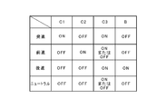
- FIG. 2 is a table collectively showing operating states of clutch mechanisms and brake mechanisms in the vehicle transmission shown in FIG. 1.
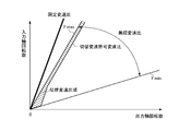
- FIG. It is a flowchart for demonstrating an example of control by the control apparatus of the transmission for vehicles which concerns on this invention. It is a figure for demonstrating the switching shift range set when performing control by the control apparatus of the transmission for vehicles concerning this invention. It is a figure for demonstrating the switching shift range set when performing control by the control apparatus of the transmission for vehicles concerning this invention. It is a flowchart for demonstrating the other example of control by the control apparatus of the belt-type continuously variable transmission which concerns on this invention.
- an automatic transmission to be controlled in the present invention includes a first transmission path having a first transmission mechanism and a second transmission path having a second transmission mechanism between an input shaft and an output shaft. Is formed. The first transmission path and the second transmission path are arranged in parallel between the input shaft and the output shaft. Then, either one of the first transmission path and the second transmission path is selected, and the torque is transmitted between the input shaft and the output shaft of the automatic transmission.
- the first transmission mechanism provided in the first transmission path constitutes a main transmission unit of the automatic transmission.
- the first speed change mechanism is a speed change mechanism capable of continuously changing the speed change ratio, and is constituted by, for example, a belt-type continuously variable speed change mechanism.
- the second speed change mechanism provided in the second transmission path constitutes a sub-transmission portion of the automatic transmission.
- the second transmission mechanism is constituted by, for example, a gear transmission mechanism.
- the gear transmission mechanism is configured to set a gear ratio that cannot be set by the belt type continuously variable transmission mechanism. Therefore, the gear transmission mechanism is configured by meshing a plurality of gears, and the gear ratio set by the gear ratio (ratio of the number of teeth) is larger than the maximum gear ratio of the belt-type continuously variable transmission mechanism.
- the gear transmission mechanism is a belt-type continuously variable transmission so that a large torque when the vehicle starts is not applied to the belt-type continuously variable transmission mechanism. It is preferable to configure so that a gear ratio larger than the maximum gear ratio of the speed change mechanism can be set. Further, in order to reduce the engine speed in a traveling vehicle and reduce the fuel consumption, the gear transmission mechanism can be configured to be able to set a gear ratio smaller than the minimum gear ratio of the belt-type continuously variable transmission mechanism. preferable.
- FIG. 1 shows an example of a specific configuration of the automatic transmission as described above.
- the automatic transmission 1 to be controlled in the present invention is a transmission mounted on a vehicle Ve, and is used by being connected to a driving force source such as an engine 2, for example.
- a torque converter 3 with a lock-up clutch is connected to the output shaft 2 a of the engine 2.
- This torque converter 3 has a conventionally known configuration.
- a turbine runner 3c is disposed opposite to a pump impeller 3b integrated with the front cover 3a.
- the pump impeller 3b and the turbine runner 3c are held via a one-way clutch (not shown).
- the stator 3d thus arranged is arranged.
- a lock-up clutch 4 that rotates integrally with the turbine runner 3c is disposed to face the inner surface of the front cover 3a. Then, according to the pressure difference between both sides of the lockup clutch 4, the lockup clutch 4 contacts the inner surface of the front cover 3a and transmits the torque, and the torque away from the inner surface of the front cover 3a. An open state is set to block transmission of.
- the input shaft 5 of the automatic transmission 1 is connected to the turbine runner 3c in the torque converter 3 described above.
- a forward / reverse switching mechanism 6 is disposed on the same axis as the input shaft 5.
- the forward / reverse switching mechanism 6 has a forward state in which torque output from the engine 2 is transmitted to a counter shaft 10a (to be described later) without changing its rotation direction, and torque output from the engine 2 is reversed in rotation direction. This is a mechanism for switching to the reverse state transmitted to the counter shaft 10a.
- the forward / reverse switching mechanism 6 is constituted by a so-called differential mechanism in which three rotating elements have a differential action.
- the forward / reverse switching mechanism 6 is configured by a double pinion type planetary gear mechanism.
- the double pinion type planetary gear mechanism constituting the forward / reverse switching mechanism 6 meshes with a sun gear 6a as an external gear, a ring gear 6b as an internal gear arranged concentrically with the sun gear 6a, and a sun gear 6a.
- the first pinion gear 6c, the second pinion gear 6c meshed with the first pinion gear 6c and the ring gear 6b, and the carrier 6e holding the first pinion gear 6c and the second pinion gear 6d so as to rotate and revolve.
- the input shaft 5 is connected to the sun gear 6a. Therefore, the sun gear 6a is an input element.
- a brake mechanism B that selectively stops the rotation of the ring gear 6b is provided. Therefore, the ring gear 6b is a reaction force element.
- the brake mechanism B is provided between a fixed part 7 such as a casing and the ring gear 6b.
- the brake mechanism B can be constituted by, for example, a friction brake such as a multi-plate brake or a meshing brake.
- the carrier 6e is an output element.
- a first clutch mechanism C1 for connecting the carrier 6e and the sun gear 6a to integrally rotate the entire planetary gear mechanism.
- the first clutch mechanism C1 is for setting the forward / reverse switching mechanism 6 to a forward state.
- the first clutch mechanism C1 only needs to be capable of selectively transmitting and interrupting torque. Therefore, the first clutch mechanism C1 may be either a friction clutch or a meshing clutch. However, it is preferable that the transmission torque capacity is configured by a friction clutch that gradually increases or decreases according to the engagement force.
- a belt type continuously variable transmission mechanism (CVT) 8 is disposed at the end of the input shaft 5 opposite to the engine 2 (left side in the example shown in FIG. 1).
- This CVT 8 has a conventionally known configuration. That is, a primary pulley 8a that is a driving side rotating member, a secondary pulley 8b that is a driven side rotating member, and a belt 8c wound around the primary pulley 8a and the secondary pulley 8b are provided.
- the primary pulley 8a and the secondary pulley 8b are configured such that the winding radius of the belt 8c changes to a large or small value by changing the width of the groove around which the belt 8c is wound. That is, the gear ratio is changed by changing the width of the groove around which the belt 8c is wound.
- the primary pulley 8a is arranged on the same axis as the input shaft 5 on the opposite side to the engine 2 with the forward / reverse switching mechanism 6 interposed therebetween.
- a primary shaft 8 d integrated with the primary pulley 8 a is connected to a sun gear 6 a that is an input element in the forward / reverse switching mechanism 6.
- the secondary pulley 8b is arranged so that the rotation center axis thereof is parallel to the rotation center axis of the primary pulley 8a.
- the secondary shaft 8e provided along the rotation center axis line of the secondary pulley 8b is provided.
- the output shaft 9 is arrange
- a second clutch mechanism C2 for selectively connecting the output shaft 9 and the secondary shaft 8e is provided.
- the second clutch mechanism C2 may be any mechanism that can selectively transmit and block torque between the secondary pulley 8b and the output shaft 9. Therefore, either a friction clutch or a meshing clutch may be used. However, it is preferable that the transmission torque capacity is configured by a friction clutch that gradually increases or decreases according to the engagement force.
- a gear train 10 is arranged in parallel with the CVT 8 described above.
- the gear train 10 is a gear transmission mechanism composed of a plurality of gears.
- the gear train 10 is configured as a speed change mechanism having a different speed ratio to be set from the CVT 8. Specifically, it is configured as a speed reduction mechanism that sets a speed ratio larger than the maximum speed ratio that can be set by CVT8, or a speed increase mechanism that sets a speed ratio that is smaller than the minimum speed ratio that can be set by CVT8.
- the gear train 10 is configured as a speed reduction mechanism.
- the CVT 8 has a configuration capable of continuously changing the gear ratio, and corresponds to the first speed change mechanism in the present invention.
- the gear train 10 has a different gear ratio to be set from the CVT 8 as described above, and corresponds to the second speed change mechanism in the present invention. Therefore, the transmission path provided with the above CVT 8, that is, the transmission path from the input shaft 5 to the output shaft 9 via the primary pulley 8a and the secondary pulley 8b of the CVT 8 corresponds to the first transmission path in the present invention. .
- the transmission path provided with the gear train 10, that is, the transmission path from the input shaft 5 to the output shaft 9 via the gear train 10 corresponds to the second transmission path in the present invention.
- the gear train 10 has a counter shaft 10a disposed in parallel to the input shaft 5 and the output shaft 9, respectively.
- a counter driven gear 10b is attached to one end (right side in the example shown in FIG. 1) of the counter shaft 10a so as to rotate integrally with the counter shaft 10a.
- the counter driven gear 10b meshes with the drive gear 6f that rotates integrally with the carrier 6e of the forward / reverse switching mechanism 6 described above.
- the counter driven gear 10b is a gear having a larger diameter than the drive gear 6f. Therefore, torque is amplified and transmitted in the direction from the drive gear 6f to the counter driven gear 10b.
- a counter drive gear 10c is attached to the other end (left side in the example shown in FIG. 1) of the counter shaft 10a so as to rotate integrally with the counter shaft 10a.
- the counter drive gear 10c is a gear having a smaller diameter than the counter driven gear 10b.
- the counter drive gear 10c is meshed with a driven gear 10d arranged so as to be able to rotate relative to the output shaft 9 on the output shaft 9 described above.
- the driven gear 10d has a larger diameter than the counter drive gear 10c. Therefore, torque is amplified and transmitted in the direction from the driven gear 10d to the counter drive gear 10c.
- the gear ratio (gear ratio) of the gear train 10 is obtained by multiplying the gear ratio between the drive gear 6f and the counter driven gear 10b and the gear ratio between the counter drive gear 10c and the driven gear 10d. It becomes.
- the gear ratio of the gear train 10 is configured such that the value is larger than the maximum gear ratio of the CVT 8.
- a third clutch mechanism C3 for selectively setting a state in which the driven gear 10d is connected to the output shaft 9 so that power can be transmitted and a state in which the power transmission between the driven gear 10d and the output shaft 9 is interrupted.
- the third clutch mechanism C3 may be configured to switch to two states of engagement and release. That is, there is no need for a configuration in which the transmission torque capacity gradually changes. Therefore, the third clutch mechanism C3 can be configured by a meshing clutch such as a dog clutch or a synchronizer. In the example shown in FIG.
- the third clutch mechanism C3 is configured such that the sleeve is fitted to a spline formed on the boss portion of the driven gear 10d and a spline formed on the hub of the output shaft 9, thereby Is connected to the output shaft 9 by a synchronizer.
- the output gear 9a is attached to the end of the output shaft 9 opposite to the CVT 8 (right side in the example shown in FIG. 1).
- a large-diameter gear 11a meshing with the output gear 9a is attached to one end (right side in the example shown in FIG. 1) of the reduction gear shaft 11b.
- a small-diameter gear 11c is attached to the other end (left side in the example shown in FIG. 1) of the reduction gear shaft 11b.
- the small diameter gear 11c meshes with the ring gear 12a of the differential 12.
- the differential 12 is configured to transmit the torque transmitted through the ring gear 12a from the left and right drive shafts 13 to drive wheels (not shown).
- An electronic control unit (ECU) 14 that controls the operation of the automatic transmission 1 is provided.
- the ECU 14 is mainly composed of a microcomputer. Then, calculation is performed in accordance with a predetermined program based on the input data and data stored in advance, and various states such as forward, reverse, or neutral, and control such as setting of a required gear ratio are executed. It is configured.
- the ECU 14 is configured to receive detection signals and information signals from various sensors.
- a pulley rotational speed sensor (not shown) that detects the rotational speeds of the primary pulley 8a and the secondary pulley 8b
- a shift position sensor (not shown) that detects a shift position selected by a shift device or a shift lever
- a detection signal from a wheel speed sensor (not shown) or the like that detects the rotational speed of each wheel of the vehicle in order to obtain the vehicle speed is input to the ECU 14.
- the automatic transmission 1 configured as described above passes through a torque transmission path (that is, the second transmission path in the present invention) provided with the gear train 10 when starting in the forward direction and when traveling backward.
- a torque transmission path that is, the second transmission path in the present invention
- the torque is transmitted to the output shaft 9.
- torque transmission path provided with the CVT 8 (that is, the first transmission path in the present invention).
- the drive position is selected by a shift device or a shift lever (not shown)
- the first clutch mechanism C1 and the third clutch mechanism C3 are engaged, and the second clutch mechanism C2 and the brake mechanism B are released.
- the torque output by the engine 2 is transmitted to the sun gear 6a of the forward / reverse switching mechanism 6 via the input shaft 5 by setting each engagement mechanism as shown in the table of FIG. The Further, it is transmitted to the carrier 6e through the first clutch mechanism C1.
- the forward / reverse switching mechanism 6 transmits the input torque from the carrier 6e to the drive gear 6f without causing any speed increasing action and speed reducing action.
- the driven gear 10d in the gear train 10 is connected to the output shaft 9 by the third clutch mechanism C3
- the torque of the input shaft 5 is transmitted to the output shaft 9 via the gear train 10. Then, torque is transmitted from the output gear 9a to the left and right drive wheels via the gear train 11 and the differential 12, and the vehicle starts.
- the gear train 10 functions as a speed reduction mechanism.
- the gear ratio is larger than the maximum gear ratio that can be set by the CVT 8.
- the CVT 8 is not subjected to a large torque at the start. For this reason, it is not necessary to increase the hydraulic pressure for setting the transmission torque capacity of the CVT 8. Therefore, consumption of power for generating hydraulic pressure is reduced, fuel consumption can be improved, and durability of CVT 8 can be improved.
- the first clutch mechanism C1 When the vehicle speed is increased to a predetermined vehicle speed after starting, the first clutch mechanism C1 is released with the gear ratio of the CVT 8 set to the maximum gear ratio or a gear ratio close thereto. At the same time, the second clutch mechanism C2 is engaged. In this case, the forward / reverse switching mechanism 6 is in a state of so-called free rotation because the first clutch mechanism C1 is further released while the brake mechanism B is released. As a result, power transmission between the input shaft 5 and the gear train 10 is interrupted. On the other hand, the secondary pulley 8b is connected to the output shaft 9 by the second clutch mechanism C2. As a result, the input shaft 5 and the output shaft 9 are coupled so as to transmit torque via the CVT 8. Therefore, the engine speed can be set to a speed with good fuel consumption by gradually decreasing the gear ratio by the CVT 8 or changing it according to the vehicle speed and the accelerator opening.
- the gear ratio in this case is a gear ratio obtained by multiplying the gear ratio by the gear train 10 and the gear ratio by the planetary gear mechanism constituting the forward / reverse switching mechanism 6. Then, torque is transmitted from the output gear 9a to the left and right drive wheels via the gear train 11 and the differential 12, and the vehicle travels backward.
- the neutral state in which the power transmission between the engine 2 and the output shaft 9 is interrupted can be set by opening both the first clutch mechanism C1 and the second clutch mechanism C2. It can.
- the engagement / release state of the first clutch mechanism C1, the second clutch mechanism C2, the third clutch mechanism C3, and the brake mechanism B, and controlling the operation of the forward / reverse switching mechanism 6, A forward state, a reverse state, and a neutral state can be set, respectively.
- the first clutch mechanism C1, the second clutch mechanism C2, and the brake mechanism B are the first transmission path provided with the CVT 8 as the path for transmitting power between the input shaft 5 and the output shaft 9.
- the automatic transmission 1 to be controlled in the present invention has a clutch-to-clutch when performing a switching shift between the transmission path having the CVT 8 and the transmission path having the gear train 10.
- the control By executing the control, it is possible to suppress the engagement shock in the clutch mechanism at the time of switching.
- friction material wear and frictional heat inevitably occur due to friction during slip engagement.
- the rotational speed difference between the engagement members of the clutch mechanism is large, wear and heat generation of the friction material also increase, and the durability of the clutch mechanism decreases accordingly.
- the engagement shock is increased.
- the control device can execute the switching shift in an appropriate state based on the actual transmission ratio actually set in the CVT 8 when executing the switching shift as described above. It is configured. Specifically, the gear ratio range where the actual gear ratio of the CVT 8 when executing the switching gear shift is such that the rotational speed difference between the engaging members of the clutch mechanism that is engaged during the switching gear shifting is less than or equal to a predetermined value. When it does not enter, it is comprised so that switching shift may not be performed.
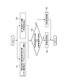
- FIG. 3 is a first control example executed by the control device according to the present invention, and is a flowchart for explaining basic control contents of the present invention.
- the routine shown in this flowchart is repeatedly executed every predetermined short time.
- it is first determined whether or not it is necessary to execute switching of the power transmission path between the first transmission path provided with the CVT 8 and the second transmission path provided with the gear train 10. That is, it is determined whether or not a switching shift is necessary (step S1).
- This is a control generally executed in the conventional shift control, and is determined based on the vehicle speed or the output shaft speed of the output shaft 9, and the accelerator opening or the throttle opening. For example, it is possible to determine whether or not a switching shift is necessary based on a map or shift diagram set for the output shaft speed and the accelerator opening.
- step S2 it is determined whether or not the execution of the switching shift can be permitted. That is, it is determined whether or not the switching speed can be changed (step S2).
- the control device is configured to determine whether or not to execute the switching shift in addition to the determination of whether or not to execute the conventional switching shift. Therefore, in this step S2, it is determined whether or not switching can be performed based on the actual transmission ratio of CVT8. Specifically, the actual gear ratio currently set in CVT 8 is obtained, and the actual gear ratio is compared with the switching gear ratio region.
- the switching gear ratio region is, in other words, the switching gear shift permission region, which defines the range of the gear ratio of the CVT 8 that is set in order to determine the state in which the switching gear shift can be appropriately executed. .
- the speed ratio (fixed speed ratio) set by the gear train 10 is the speed ratio (continuously variable speed ratio) that can be set by the CVT 8.
- the switching gear ratio region when the maximum gear ratio ( ⁇ max) is larger than () is shown.
- FIG. 5 shows switching when the gear ratio (fixed gear ratio) set by the gear train 10 is smaller than the minimum gear ratio ( ⁇ min) of the gear ratios (continuously variable gear ratio) that can be set by the CVT 8.
- the gear ratio range is shown.
- the state in which the above-described switching shift can be appropriately executed means that the rotational speed difference between the engaging members in the clutch mechanism that is controlled from disengagement to engagement when executing the switching shift is determined in advance. It is a state that is below a predetermined value.
- the change gear ratio range is set so that the rotational speed difference in the second clutch mechanism C2 to be engaged is a predetermined value or less.
- the switching gear ratio range is set so as to be equal to or less than a predetermined value.
- step S1 may be performed first, or step S2 may be performed first.
- step S3 the state of the automatic transmission 1 is determined to require the switching shift, and It is determined whether or not the switching shift is permitted (step S3). Specifically, it is determined from the shift diagram or map of the automatic transmission 1 that it is necessary to execute the switching shift, and the actual transmission ratio of the CVT 8 is a transmission ratio within the switching gear ratio range, so that the switching shift is executed. It is determined whether or not it is in a permitted state.
- step S3 determines whether the state of the automatic transmission 1 is determined to require a switching shift and the switching shift is permitted, and if the determination in step S3 is affirmative, the process proceeds to step S4. Then, a switching shift is executed. Specifically, in the case of a shift gear change from the second transmission path to the first transmission path, the first clutch mechanism C1 is controlled from engagement to release and the second clutch C2 is controlled from release to engagement. The Further, in the case of a shift shift from the first transmission path to the second transmission path, the first clutch mechanism C1 is controlled from disengagement to engagement, and the second clutch C2 is controlled from engagement to disengagement. Thereafter, this routine is once terminated.
- step S3 the state of the automatic transmission 1 has not yet been determined that the switching shift is not necessary, has not yet been permitted to be switched, or has not yet been determined that the switching shift is necessary. If the determination is negative in step S3 because the switching shift is not yet permitted, the process proceeds to step S5. Then, execution of the switching shift is prohibited. In other words, the execution of the switching shift is kept on standby until the determination in step S3 is positive. Thereafter, this routine is once terminated.
- the transmission path for transmitting power between the input shaft 5 and the output shaft 9 of the automatic transmission 1 is set between the first transmission path and the second transmission path.
- the switching shift to be switched at it is determined whether or not the switching shift can be performed. That is, it is determined whether or not the actual transmission ratio of the CVT 8 provided with the first transmission path is a transmission ratio within a switching transmission ratio range set in order to appropriately execute the switching transmission.
- the actual gear ratio of the CVT 8 is a gear ratio outside the switching gear ratio range, the switching gear shift is not executed.
- the switching gear shift it is determined whether or not it is necessary to execute a switching shift similar to the conventional shift control, and whether or not the switching shift can be performed is determined. Then, in addition to the determination that execution of the switching gear shift is necessary, when the execution of the switching gear shift is permitted, that is, when the actual gear ratio of the CVT 8 is a gear ratio within the switching gear ratio range, the switching gear shift is performed. Executed. Therefore, for example, even when it is determined that it is necessary to execute the switching gear shift based on information on the output shaft rotation speed or the accelerator opening, the actual gear ratio of the CVT 8 set at that time is outside the switching gear ratio range. If it is the gear ratio, the switching shift is not executed.
- the switching gear shift is executed only in an appropriate driving state in which the gear ratio within the switching gear ratio range is set by the CVT 8. Therefore, it is possible to prevent or suppress a shock that occurs at the time of switching gear shift and a decrease in durability of the clutch mechanism that is engaged at the time of switching gear shifting.
- the rotational speed difference between the engaging members of the clutch mechanism is taken into consideration. Then, the switching speed ratio range is set so that the rotational speed difference becomes smaller than a predetermined value when the switching shift is executed. Therefore, when the switching shift is executed, the rotational speed difference in the clutch mechanism can be kept at a predetermined value or less. For this reason, it is possible to reliably prevent or suppress a shock and a decrease in durability of the clutch mechanism that occur during the switching shift due to a large rotational speed difference in the clutch mechanism.
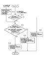
- FIG. 6 is a flowchart for explaining a second control example executed by the control device according to the present invention.
- This second control example is based on the first control example described above, and includes a correction of a threshold when setting the switching shift range, a guard timer (backup timer) when determining whether to perform the switching shift, and the like. It is the example of control provided. Further, in this second control example, an example is shown in which a shift shift from the second transmission path having the gear train 10 to the first transmission path having the CVT 8 is executed.
- step S11 it is determined whether or not the operating state of the automatic transmission 1 is in the fixed shift region on the shift diagram. This determination can be made based on the output shaft speed or vehicle speed, and the accelerator opening or throttle opening. For example, it can be determined from a shift diagram or map as shown in FIG.
- the operating state of the automatic transmission 1 is not in the fixed shift region on the shift diagram, that is, the power transmission path in the automatic transmission 1 is already set to the first transmission path with the CVT 8. If a negative determination is made in step S11, the process proceeds to step S12. Then, execution of the switching shift is prohibited.
- the shift control in the CVT 8 in this case is executed as usual based on a shift diagram or map. Thereafter, this routine is once terminated. As described above, in this control example, the control is based on the case where the shift shift from the second transmission path to the first transmission path is executed. Therefore, in this case, this routine is temporarily terminated without executing the control according to the present invention.
- This switching speed change permission gear ratio is a gear ratio (continuously variable gear ratio) of CVT 8 which is a threshold value for defining the switching gear ratio range in the present invention.
- this switching speed permission gear ratio is, for example, as shown in FIG. 5 described above, when executing the switching speed shift from the first transmission path having the CVT 8 to the second transmission path having the gear train 10. It is set as a gear ratio that divides the switching gear ratio region together with the minimum gear ratio ⁇ min of CVT8.
- the control for setting the switching speed change permission gear ratio and the switching speed ratio range will be specifically described.
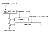
- the block diagram of FIG. 7 shows an image of the control content when setting the switching speed permission gear ratio.
- This switching speed change permission gear ratio is obtained based on, for example, the output shaft speed of the output shaft 9 and the input torque transmitted to the input shaft 5. More specifically, the switching shift permission gear ratio is determined such that the greater the input torque, the narrower the switching gear ratio range.
- a map relating to the input torque, the output shaft rotational speed, and the switching speed change permission gear ratio can be set in advance, and the switching speed permission speed ratio can be obtained from the map.
- the clutch mechanism slips due to a large rotational speed difference in the clutch mechanism that is engaged when this switching shift is executed (that is, the second clutch mechanism C2 in this control example). Even if the time increases, the amount of heat generated by friction at that time is relatively small. Therefore, the allowable range of the rotational speed difference in the clutch mechanism can be set relatively wide.
- the friction plate wears and generates heat due to friction when the clutch mechanism is engaged. Therefore, if the time during which the engaging members slip when engaging the clutch mechanism becomes long, the durability of the clutch mechanism may be affected.
- the frictional plate wear in the clutch mechanism as described above can be reduced by setting the switching speed change gear ratio so that the larger the input torque as described above, the narrower the speed ratio. It is possible to reduce or reduce the amount of heat generation and to prevent or suppress a decrease in durability of the clutch mechanism.
- correction considering the acceleration of the vehicle Ve can be performed on the switching shift permission gear ratio obtained based on the output shaft rotational speed and the input torque as described above.
- the value of the switching speed change permission gear ratio is corrected so that the width of the switching speed ratio region becomes wider as the acceleration of the vehicle Ve increases.
- the change speed of the output shaft rotation speed is calculated, and the value of the switching speed permission speed ratio is corrected so that the width of the switching speed ratio area becomes wider as the change speed of the output shaft speed increases.
- a map related to the change speed of the acceleration or the output shaft rotational speed and the switching speed change permission gear ratio is set in advance, and the switching speed change permission speed ratio is corrected based on the map. it can.
- the gear train 10 When the shift from CVT to CVT8 is executed, if the amount of change in vehicle speed or the acceleration of the vehicle Ve is large, the vehicle speed may increase faster than the shift in CVT8. As a result, the gear ratio of CVT 8 may not enter the switching gear ratio range, and the switching gear shift may not be executed.
- the width of the switching gear ratio range becomes relatively wide. In this way, the value of the switching speed change permission gear ratio is corrected. Therefore, it is possible to avoid the situation where the switching shift as described above is not executed, and to appropriately execute the switching shift.
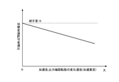
- the magnitude of the driver's acceleration intention is estimated.
- the magnitude of the driver's intention to accelerate can be estimated based on, for example, at least one of the operation amount and the operation speed of the accelerator operation by the driver. That is, it can be estimated that the greater the amount of accelerator operation, the greater the driver's intention to accelerate. Alternatively, it can be estimated that the driver's intention to accelerate increases as the operation speed of the accelerator operation increases. Alternatively, it can be estimated that the driver's intention to accelerate increases as the operation amount and operation speed of the accelerator operation increase.
- the width of the switching gear ratio area becomes wider as the estimated driver's intention to accelerate is larger.
- the value of the switching speed change permission gear ratio is corrected. Therefore, it is possible to avoid the situation where the switching shift is not executed as described above, and to execute the switching shift more appropriately.
- the correction for increasing the width of the switching gear ratio region as the acceleration for example, a map relating to the driver's intention to accelerate and the switching gear permission gear ratio as shown in FIG. It is possible to correct the switching speed change permission gear ratio in advance based on the map.
- step S11 determines whether or not the actual gear ratio set in CVT 8 is a gear ratio within the switching gear shift permission area, that is, within the switching gear ratio area, or whether or not switching from a fixed gear to a continuously variable transmission. It is determined whether or not the state in which the determination about is deviated has exceeded a predetermined time ⁇ .
- the state in which the determination of switching from a fixed shift to a continuously variable shift and the determination of whether or not a switch shift is possible is a determination of whether to switch from a fixed shift to a continuously variable shift. This is a state in which it is determined that the switching shift is necessary, and the execution of the switching shift is not permitted in the determination of whether or not the switching shift is possible.
- step S14 The state in which the actual gear ratio set in CVT8 is a gear ratio outside the switching gear ratio range, and the actual gear ratio is a gear ratio outside the switching gear ratio range, the switching gear shift is necessary in determining whether or not the switching gear shift is necessary. If the determination at step S14 is negative because the predetermined time ⁇ has not yet elapsed from the point of determination, the process proceeds to step S15. Then, execution of the switching shift is prohibited. Note that the shift control in the CVT 8 in this case is executed with the target gear ratio set to the maximum gear ratio ⁇ max or a gear ratio within the switching gear ratio range. Alternatively, it is executed as usual based on a shift map or map. Thereafter, this routine is once terminated.
- step S14 if the actual gear ratio set in CVT 8 is the gear ratio within the switching gear ratio range and the determination is affirmative in step S14, the process proceeds to step S16. Then, a switching shift is executed. Note that the shift control in the CVT 8 in this case is executed as usual based on a shift diagram or map. Thereafter, this routine is once terminated.
- step S14 Even when the predetermined time ⁇ or more has already elapsed from the time when it is determined that the switching shift is necessary in the negative determination, a positive determination is made in step S14. And it progresses to step S16 and the same control as the above is performed. That is, the switching shift is executed.
- the switching speed ratio range set for determining whether or not the switching shift can be performed as described above is at least one of the output shaft rotational speed and the input torque.
- the value of the switching speed change permission gear ratio is set so that the width of the switching speed ratio range becomes narrower as the input torque increases.
- the value of the switching speed change permission gear ratio is corrected and set so that the width of the switching speed ratio region becomes wider as the acceleration of the vehicle Ve and the change speed of the output shaft rotation speed are larger.
- the driver's intention to accelerate is estimated, and the value of the switching speed-permitted gear ratio is corrected and set so that the greater the estimated intention to accelerate, the wider the switching gear ratio area. Therefore, an appropriate switching shift can be executed in accordance with the traveling state of the vehicle Ve and the driving state of the automatic transmission 1.
- the switching gear shift when it is determined that execution of the switching gear shift is necessary as described above, the execution of the switching gear shift is prohibited because the actual gear ratio of the CVT 8 is a gear ratio outside the switching gear ratio range. Even if it is, the switching shift is executed when a predetermined time ⁇ or more has passed since it was determined that the switching shift is necessary. For example, when the change amount or acceleration of the vehicle speed is large, the vehicle speed increases faster than the shift in the CVT 8, and as a result, the switch gear shift may not be executed without the gear ratio of the CVT 8 being within the switch gear ratio range. is there. On the other hand, in the present invention, by providing the guard for the predetermined time ⁇ as described above in advance, the situation where the switching shift as described above is not executed is avoided, and the necessity of the switching shift is determined. The switching shift can be appropriately executed.
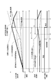
- FIG. 10 is a time chart showing changes in the rotational speeds of the input shaft and the output shaft, and changes in the target gear ratio and the actual gear ratio when the shift control relating to the switching gear shift according to the present invention is executed.
- the vehicle Ve is suddenly braked and stopped, the vehicle Ve is restarted in a state where the actual gear ratio of the CVT 8 has not returned to the maximum gear ratio or a large gear ratio suitable for starting. The case of starting is assumed.
- the actual transmission ratio of CVT 8 deviates toward the smaller transmission ratio with respect to the target transmission ratio of CVT 8 set based on the output shaft rotational speed of output shaft 9. Yes.
- the automatic transmission 1 includes a second transmission having a gear train 10 that sets a gear ratio larger than the maximum gear ratio of the CVT 8. It is set to a state where power is transmitted via a route.
- the switching speed permission speed ratio is the speed ratio of CVT 8 serving as a threshold value for defining the switching speed ratio range in the present invention.
- the CVT 8 While the vehicle Ve is started after the time t1, the CVT 8 is also shifting. Then, at time t4, when the actual transmission ratio of CVT8 reaches the switching shift permission transmission ratio, that is, when the actual transmission ratio of CVT8 becomes a transmission ratio within the switching transmission ratio range, switching from the second transmission path to the first transmission path is performed. Shifting is performed. In the conventional control, the switching shift is executed at time t2. On the other hand, in the present invention, execution of the switching shift is prohibited during a period T1 from time t2 to time t4 when the switching shift is permitted in the determination of whether or not the switching shift is possible.
- the actual gear ratio of the CVT 8 is not immediately followed by the target gear ratio, but is controlled so as to follow the switching gear shift permission gear ratio until time t5.
- the actual speed ratio of the CVT 8 is controlled to follow the target speed ratio.
- the switching shift permission is allowed in consideration of the friction in the second clutch mechanism C2. Control is performed so as to follow the gear ratio. Then, after time t5, control is performed so as to follow the original target gear ratio. That is, normal shift control is performed.
- the functional means for executing steps S3, S4, S11, S14, and S16 corresponds to the “execution means” in the present invention.
- the functional means for executing steps S2 and S13 corresponds to the “setting means” in the present invention.
- the automatic transmission 1 to be controlled in the present invention May be configured such that a gear ratio that cannot be set by the CVT 8 is set by the gear train 10. Therefore, in the automatic transmission 1 of the present invention, for example, the gear ratio by the gear train 10 can be configured to be smaller than the minimum gear ratio in the CVT 8. In such a configuration, when the lockup clutch 4 is engaged or when the engine 2 is driven with a low load, the engine speed can be made lower than that when the torque is transmitted by the CVT 8. Therefore, the fuel consumption of the engine 2 can be further improved. Further, the gear train 10 may be configured such that a plurality of gear ratios can be selectively set.
Landscapes
- Engineering & Computer Science (AREA)
- General Engineering & Computer Science (AREA)
- Mechanical Engineering (AREA)
- Control Of Transmission Device (AREA)
Abstract
Description
図3は、この発明に係る制御装置により実行される第1の制御例であって、この発明の基本的な制御内容を説明するためのフローチャートである。このフローチャートで示されるルーチンは、所定の短時間毎に繰り返し実行される。図3において、先ず、CVT8を備えた第1伝動経路とギヤ列10を備えた第2伝動経路との間で、動力伝達経路の切り替えを実行する必要があるか否かについて判断される。すなわち、切替変速の要否について判断される(ステップS1)。これは、従来の変速制御において一般的に実行される制御であり、車速あるいは出力軸9の出力軸回転数、および、アクセル開度あるいはスロットル開度に基づいて判断される。例えば、出力軸回転数とアクセル開度とに関して設定されたマップあるいは変速線図を基に、切替変速の要否について判断することができる。
図6は、この発明に係る制御装置により実行される第2の制御例を説明するためのフローチャートである。この第2の制御例は、前述の第1の制御例をベースにして、切替変速域を設定する際の閾値の補正や、切替変速の実行を判断する際のガードタイマ(バックアップタイマ)等を設けた制御例である。また、この第2の制御例では、ギヤ列10を備えた第2伝動経路からCVT8を備えた第1伝動経路への切替変速を実行する場合の例を示している。図6において、先ず、自動変速機1の運転状態が、変速線図上において固定変速領域にあるか否かが判断される(ステップS11)。この判断は、出力軸回転数あるいは車速、および、アクセル開度あるいはスロットル開度に基づいて行うことができる。例えば、前述の図4で示したような変速線図もしくはマップから判断することができる。
Claims (8)
- 車両の駆動力源からトルクが入力される入力軸と出力部材へトルクを出力する出力軸との間に、変速比を連続的に変化させることが可能な第1変速機構を備えた第1伝動経路と、前記第1変速機構とは設定する変速比が異なる第2変速機構を備えた第2伝動経路とが並列に設けられ、前記第1伝動経路および前記第2伝動経路のいずれか一方を経由して前記入力軸と前記出力軸との間で動力伝達を行う車両用変速機の制御装置において、
所定のクラッチ機構を係合させることにより前記動力伝達を行う経路を前記第1伝達経路と前記第2伝達経路との間で切り替える切替変速を実行する実行手段と、
前記切替変速を実行する際に互いに係合する前記クラッチ機構の係合部材間における回転数差が所定値以下となるように前記第1変速機構の変速比の範囲を規定した切替変速比域を設定する設定手段とを備え、
前記第1変速機構で前記切替変速比域外の変速比が設定されている場合には、前記切替変速を実行しないように構成されている
ことを特徴とする車両用変速機の制御装置。
- 運転者によるアクセル操作の変化量および変化速度の少なくともいずれかを検出する手段を更に備え、
前記実行手段は、車速、前記出力軸の出力軸回転数、および運転者によるアクセル操作の少なくともいずれかに関する情報を基に前記切替変速の実行の要否を判断するとともに、前記切替変速の実行が必要であると判断し、かつ、前記第1変速機構で前記切替変速比域内の変速比が設定されている場合に、前記切替変速を実行する手段を含むことを特徴とする請求項1に記載の車両用変速機の制御装置。
- 前記実行手段は、前記切替変速の実行が必要であると判断した後に、前記第1変速機構で前記切替変速比域外の変速比が設定されている時間が所定時間以上経過した場合には、前記切替変速を実行する手段を含むことを特徴とする請求項2に記載の車両用変速機の制御装置。
- 前記設定手段は、前記出力軸の出力軸回転数および前記入力軸に入力される入力トルクの少なくともいずれかに関する情報に応じて、前記切替変速比域の幅を変更して設定する手段を含むことを特徴とする請求項1から3のいずれかに記載の車両用変速機の制御装置。
- 前記設定手段は、前記入力トルクが大きいほど、前記切替変速比域の幅を狭くする手段を含むことを特徴とする請求項4に記載の車両用変速機の制御装置。
- 前記設定手段は、前記出力軸回転数の変化速度が大きいほど、前記切替変速比域の幅を広くする手段を含むことを特徴とする請求項4または5に記載の車両用変速機の制御装置。
- 前記車両の加速度を検出する手段を更に備え、
前記設定手段は、前記加速度が大きいほど、前記切替変速比域の幅を広くする手段を含むことを特徴とする請求項4から6のいずれかに記載の車両用変速機の制御装置。
- 運転者によるアクセル操作の操作量および操作速度の少なくともいずれかを検出する手段を更に備え、
前記設定手段は、前記アクセル操作の操作量および操作速度の少なくともいずれかが大きいほど、前記切替変速比域の幅を広くする手段を含むことを特徴とする請求項4から7のいずれかに記載の車両用変速機の制御装置。
Priority Applications (6)
| Application Number | Priority Date | Filing Date | Title |
|---|---|---|---|
| US14/386,349 US9568098B2 (en) | 2013-04-16 | 2013-04-16 | Controller for vehicle transmission |
| EP13878526.6A EP2988032B1 (en) | 2013-04-16 | 2013-04-16 | Control device for vehicle transmission |
| CN201380015495.9A CN105143729B (zh) | 2013-04-16 | 2013-04-16 | 车辆用变速器的控制装置 |
| PCT/JP2013/061316 WO2014170959A1 (ja) | 2013-04-16 | 2013-04-16 | 車両用変速機の制御装置 |
| JP2014530851A JP5655995B1 (ja) | 2013-04-16 | 2013-04-16 | 車両用変速機の制御装置 |
| KR1020147026205A KR101635302B1 (ko) | 2013-04-16 | 2013-04-16 | 차량용 변속기의 제어 장치 |
Applications Claiming Priority (1)
| Application Number | Priority Date | Filing Date | Title |
|---|---|---|---|
| PCT/JP2013/061316 WO2014170959A1 (ja) | 2013-04-16 | 2013-04-16 | 車両用変速機の制御装置 |
Publications (1)
| Publication Number | Publication Date |
|---|---|
| WO2014170959A1 true WO2014170959A1 (ja) | 2014-10-23 |
Family
ID=51730932
Family Applications (1)
| Application Number | Title | Priority Date | Filing Date |
|---|---|---|---|
| PCT/JP2013/061316 Ceased WO2014170959A1 (ja) | 2013-04-16 | 2013-04-16 | 車両用変速機の制御装置 |
Country Status (6)
| Country | Link |
|---|---|
| US (1) | US9568098B2 (ja) |
| EP (1) | EP2988032B1 (ja) |
| JP (1) | JP5655995B1 (ja) |
| KR (1) | KR101635302B1 (ja) |
| CN (1) | CN105143729B (ja) |
| WO (1) | WO2014170959A1 (ja) |
Cited By (8)
| Publication number | Priority date | Publication date | Assignee | Title |
|---|---|---|---|---|
| JP2017036783A (ja) * | 2015-08-07 | 2017-02-16 | トヨタ自動車株式会社 | 動力伝達装置の制御装置 |
| CN106438981A (zh) * | 2015-08-06 | 2017-02-22 | 丰田自动车株式会社 | 车辆的控制装置 |
| JP2018076892A (ja) * | 2016-11-07 | 2018-05-17 | トヨタ自動車株式会社 | 車両用駆動装置の制御装置 |
| JP2018105495A (ja) * | 2016-12-28 | 2018-07-05 | トヨタ自動車株式会社 | 車両用動力伝達装置の制御装置 |
| JP2019090457A (ja) * | 2017-11-13 | 2019-06-13 | トヨタ自動車株式会社 | 車両用動力伝達装置の制御装置 |
| DE102019202628A1 (de) | 2018-03-02 | 2019-09-05 | Toyota Jidosha Kabushiki Kaisha | Steuergerät eines fahrzeugs |
| JP2019173818A (ja) * | 2018-03-27 | 2019-10-10 | トヨタ自動車株式会社 | 車両用動力伝達装置の制御装置 |
| US10683933B2 (en) | 2017-11-24 | 2020-06-16 | Toyota Jidosha Kabushiki Kaisha | Control apparatus for vehicle drive-force transmitting apparatus |
Families Citing this family (9)
| Publication number | Priority date | Publication date | Assignee | Title |
|---|---|---|---|---|
| KR101770053B1 (ko) * | 2013-06-12 | 2017-08-21 | 도요타 지도샤(주) | 차량의 제어 장치 |
| WO2014199457A1 (ja) * | 2013-06-12 | 2014-12-18 | トヨタ自動車株式会社 | 車両の制御装置および方法 |
| WO2016168138A1 (en) * | 2015-04-17 | 2016-10-20 | Borgwarner Inc. | Dual-pass continuously variable automatic transmission |
| JP6455606B2 (ja) * | 2015-10-30 | 2019-01-23 | アイシン・エィ・ダブリュ株式会社 | 自動変速機 |
| DE102016002220A1 (de) | 2016-02-25 | 2017-08-31 | GM Global Technology Operations LLC (n. d. Gesetzen des Staates Delaware) | Kraftfahrzeug-Antriebsstrang |
| WO2017169396A1 (ja) * | 2016-03-28 | 2017-10-05 | アイシン・エィ・ダブリュ株式会社 | 制御装置 |
| KR20200026418A (ko) * | 2018-08-31 | 2020-03-11 | 현대자동차주식회사 | 차량용 무단 변속 동력전달 장치 |
| KR20200102031A (ko) | 2019-02-20 | 2020-08-31 | 현대자동차주식회사 | 차량용 무단 변속 동력전달 장치 |
| JP2021067294A (ja) * | 2019-10-18 | 2021-04-30 | トヨタ自動車株式会社 | 車両用変速機の制御装置 |
Citations (2)
| Publication number | Priority date | Publication date | Assignee | Title |
|---|---|---|---|---|
| JPH0361762A (ja) | 1989-07-27 | 1991-03-18 | Nissan Motor Co Ltd | 変速機の制御装置 |
| JP2005278387A (ja) * | 2004-02-25 | 2005-10-06 | Toyota Motor Corp | 車両用駆動装置の制御装置 |
Family Cites Families (10)
| Publication number | Priority date | Publication date | Assignee | Title |
|---|---|---|---|---|
| FR1440883A (fr) * | 1964-05-02 | 1966-06-03 | Zahnradfabrik Friedrichshafen | Système de transmission |
| ES379553A1 (es) * | 1969-05-14 | 1973-02-01 | Mtu Friedrichshafen Gmbh | Instalacion de propulsion con dos maquinas propulsoras. |
| US4867732A (en) * | 1987-08-21 | 1989-09-19 | Toyota Jidosha Kabushiki Kaisha | Control device for belt-and-pulley type continuously variable transmission for a vehicle |
| US5853343A (en) * | 1996-09-05 | 1998-12-29 | Ford Global Technologies, Inc. | Dual mode continually variable transmission |
| JP2004144138A (ja) * | 2002-10-22 | 2004-05-20 | Honda Motor Co Ltd | 車両用変速機 |
| JP4483819B2 (ja) * | 2005-04-28 | 2010-06-16 | 株式会社豊田中央研究所 | 動力伝達システム |
| CN201202787Y (zh) * | 2007-12-11 | 2009-03-04 | 山东交通学院 | 复合式汽车变速器 |
| JP4774108B2 (ja) * | 2009-03-02 | 2011-09-14 | 日産自動車株式会社 | 自動変速機の制御装置 |
| DE102009002921A1 (de) * | 2009-05-08 | 2010-11-11 | Zf Friedrichshafen Ag | Verfahren zum Betreiben eines Antriebsstrangs |
| JP4913848B2 (ja) * | 2009-07-28 | 2012-04-11 | 本田技研工業株式会社 | 自動変速機の制御装置 |
-
2013
- 2013-04-16 WO PCT/JP2013/061316 patent/WO2014170959A1/ja not_active Ceased
- 2013-04-16 JP JP2014530851A patent/JP5655995B1/ja not_active Expired - Fee Related
- 2013-04-16 US US14/386,349 patent/US9568098B2/en not_active Expired - Fee Related
- 2013-04-16 EP EP13878526.6A patent/EP2988032B1/en not_active Not-in-force
- 2013-04-16 CN CN201380015495.9A patent/CN105143729B/zh not_active Expired - Fee Related
- 2013-04-16 KR KR1020147026205A patent/KR101635302B1/ko not_active Expired - Fee Related
Patent Citations (3)
| Publication number | Priority date | Publication date | Assignee | Title |
|---|---|---|---|---|
| JPH0361762A (ja) | 1989-07-27 | 1991-03-18 | Nissan Motor Co Ltd | 変速機の制御装置 |
| JP2847780B2 (ja) * | 1989-07-27 | 1999-01-20 | 日産自動車株式会社 | 変速機の制御装置 |
| JP2005278387A (ja) * | 2004-02-25 | 2005-10-06 | Toyota Motor Corp | 車両用駆動装置の制御装置 |
Non-Patent Citations (1)
| Title |
|---|
| See also references of EP2988032A4 |
Cited By (10)
| Publication number | Priority date | Publication date | Assignee | Title |
|---|---|---|---|---|
| CN106438981A (zh) * | 2015-08-06 | 2017-02-22 | 丰田自动车株式会社 | 车辆的控制装置 |
| JP2017036783A (ja) * | 2015-08-07 | 2017-02-16 | トヨタ自動車株式会社 | 動力伝達装置の制御装置 |
| JP2018076892A (ja) * | 2016-11-07 | 2018-05-17 | トヨタ自動車株式会社 | 車両用駆動装置の制御装置 |
| JP2018105495A (ja) * | 2016-12-28 | 2018-07-05 | トヨタ自動車株式会社 | 車両用動力伝達装置の制御装置 |
| JP2019090457A (ja) * | 2017-11-13 | 2019-06-13 | トヨタ自動車株式会社 | 車両用動力伝達装置の制御装置 |
| US10683933B2 (en) | 2017-11-24 | 2020-06-16 | Toyota Jidosha Kabushiki Kaisha | Control apparatus for vehicle drive-force transmitting apparatus |
| DE102019202628A1 (de) | 2018-03-02 | 2019-09-05 | Toyota Jidosha Kabushiki Kaisha | Steuergerät eines fahrzeugs |
| US10914375B2 (en) | 2018-03-02 | 2021-02-09 | Toyota Jidosha Kabushiki Kaisha | Control device of vehicle |
| JP2019173818A (ja) * | 2018-03-27 | 2019-10-10 | トヨタ自動車株式会社 | 車両用動力伝達装置の制御装置 |
| JP7114978B2 (ja) | 2018-03-27 | 2022-08-09 | トヨタ自動車株式会社 | 車両用油圧制御装置 |
Also Published As
| Publication number | Publication date |
|---|---|
| KR101635302B1 (ko) | 2016-06-30 |
| US20160091090A1 (en) | 2016-03-31 |
| CN105143729B (zh) | 2018-04-06 |
| US9568098B2 (en) | 2017-02-14 |
| JP5655995B1 (ja) | 2015-01-21 |
| KR20140148386A (ko) | 2014-12-31 |
| JPWO2014170959A1 (ja) | 2017-02-16 |
| EP2988032B1 (en) | 2018-07-18 |
| CN105143729A (zh) | 2015-12-09 |
| EP2988032A4 (en) | 2017-04-19 |
| EP2988032A1 (en) | 2016-02-24 |
Similar Documents
| Publication | Publication Date | Title |
|---|---|---|
| JP5655995B1 (ja) | 車両用変速機の制御装置 | |
| JP6115631B2 (ja) | 車両の制御装置および方法 | |
| JP5234171B2 (ja) | 駆動力制御装置 | |
| JP6176197B2 (ja) | 車両の制御装置 | |
| JP6332196B2 (ja) | 動力伝達装置の制御装置 | |
| JP6102466B2 (ja) | 車両用変速機の制御装置 | |
| JP6015852B2 (ja) | 車両の制御装置および方法 | |
| JP6911711B2 (ja) | 車両用動力伝達装置の制御装置 | |
| JP6879197B2 (ja) | 車両用動力伝達装置の制御装置 | |
| JP6355940B2 (ja) | 車両用変速装置 | |
| JP2017036783A (ja) | 動力伝達装置の制御装置 | |
| JP5962868B2 (ja) | 車両用変速機の制御装置 | |
| JP6790750B2 (ja) | 車両用動力伝達装置の制御装置 | |
| JP6098303B2 (ja) | 無段変速機の制御装置 | |
| JP6891820B2 (ja) | 車両用変速機の制御装置 | |
| WO2014147779A1 (ja) | 自動変速機の制御装置 | |
| JP6500085B2 (ja) | 無段変速機の制御装置、及びその制御方法 | |
| JP6984412B2 (ja) | 変速機の制御装置 | |
| JP6060780B2 (ja) | 車両の発進制御装置 | |
| JP6036484B2 (ja) | 無段変速機の制御装置 | |
| JP6930430B2 (ja) | 変速機の制御装置 | |
| JP7109858B2 (ja) | 変速機の制御装置 | |
| JP2002276789A (ja) | 無段変速機の変速制御装置 | |
| JP6254017B2 (ja) | 車両用変速装置 | |
| JP2014224562A (ja) | 自動変速機の制御装置 |
Legal Events
| Date | Code | Title | Description |
|---|---|---|---|
| WWE | Wipo information: entry into national phase |
Ref document number: 201380015495.9 Country of ref document: CN |
|
| ENP | Entry into the national phase |
Ref document number: 2014530851 Country of ref document: JP Kind code of ref document: A |
|
| ENP | Entry into the national phase |
Ref document number: 20147026205 Country of ref document: KR Kind code of ref document: A |
|
| WWE | Wipo information: entry into national phase |
Ref document number: 14386349 Country of ref document: US Ref document number: 2013878526 Country of ref document: EP |
|
| 121 | Ep: the epo has been informed by wipo that ep was designated in this application |
Ref document number: 13878526 Country of ref document: EP Kind code of ref document: A1 |
|
| REG | Reference to national code |
Ref country code: BR Ref legal event code: B01A Ref document number: 112014023165 Country of ref document: BR |
|
| NENP | Non-entry into the national phase |
Ref country code: DE |
|
| ENP | Entry into the national phase |
Ref document number: 112014023165 Country of ref document: BR Kind code of ref document: A2 Effective date: 20140918 |