WO2014171133A1 - モータのロータ・コアに用いる磁性板及びその製造方法 - Google Patents
モータのロータ・コアに用いる磁性板及びその製造方法 Download PDFInfo
- Publication number
- WO2014171133A1 WO2014171133A1 PCT/JP2014/002135 JP2014002135W WO2014171133A1 WO 2014171133 A1 WO2014171133 A1 WO 2014171133A1 JP 2014002135 W JP2014002135 W JP 2014002135W WO 2014171133 A1 WO2014171133 A1 WO 2014171133A1
- Authority
- WO
- WIPO (PCT)
- Prior art keywords
- magnetic plate
- edge
- rotor core
- main body
- plate used
- Prior art date
- Legal status (The legal status is an assumption and is not a legal conclusion. Google has not performed a legal analysis and makes no representation as to the accuracy of the status listed.)
- Ceased
Links
Images







Classifications
-
- H—ELECTRICITY
- H02—GENERATION; CONVERSION OR DISTRIBUTION OF ELECTRIC POWER
- H02K—DYNAMO-ELECTRIC MACHINES
- H02K1/00—Details of the magnetic circuit
- H02K1/06—Details of the magnetic circuit characterised by the shape, form or construction
- H02K1/22—Rotating parts of the magnetic circuit
- H02K1/27—Rotor cores with permanent magnets
- H02K1/2706—Inner rotors
- H02K1/272—Inner rotors the magnetisation axis of the magnets being perpendicular to the rotor axis
- H02K1/274—Inner rotors the magnetisation axis of the magnets being perpendicular to the rotor axis the rotor consisting of two or more circumferentially positioned magnets
- H02K1/2753—Inner rotors the magnetisation axis of the magnets being perpendicular to the rotor axis the rotor consisting of two or more circumferentially positioned magnets the rotor consisting of magnets or groups of magnets arranged with alternating polarity
- H02K1/276—Magnets embedded in the magnetic core, e.g. interior permanent magnets [IPM]
-
- H—ELECTRICITY
- H02—GENERATION; CONVERSION OR DISTRIBUTION OF ELECTRIC POWER
- H02K—DYNAMO-ELECTRIC MACHINES
- H02K15/00—Processes or apparatus specially adapted for manufacturing, assembling, maintaining or repairing of dynamo-electric machines
- H02K15/02—Processes or apparatus specially adapted for manufacturing, assembling, maintaining or repairing of dynamo-electric machines of stator or rotor bodies
- H02K15/03—Processes or apparatus specially adapted for manufacturing, assembling, maintaining or repairing of dynamo-electric machines of stator or rotor bodies having permanent magnets
-
- H—ELECTRICITY
- H02—GENERATION; CONVERSION OR DISTRIBUTION OF ELECTRIC POWER
- H02K—DYNAMO-ELECTRIC MACHINES
- H02K1/00—Details of the magnetic circuit
- H02K1/06—Details of the magnetic circuit characterised by the shape, form or construction
- H02K1/22—Rotating parts of the magnetic circuit
- H02K1/27—Rotor cores with permanent magnets
-
- H—ELECTRICITY
- H02—GENERATION; CONVERSION OR DISTRIBUTION OF ELECTRIC POWER
- H02K—DYNAMO-ELECTRIC MACHINES
- H02K1/00—Details of the magnetic circuit
- H02K1/06—Details of the magnetic circuit characterised by the shape, form or construction
- H02K1/22—Rotating parts of the magnetic circuit
- H02K1/27—Rotor cores with permanent magnets
- H02K1/2706—Inner rotors
- H02K1/272—Inner rotors the magnetisation axis of the magnets being perpendicular to the rotor axis
- H02K1/274—Inner rotors the magnetisation axis of the magnets being perpendicular to the rotor axis the rotor consisting of two or more circumferentially positioned magnets
- H02K1/2753—Inner rotors the magnetisation axis of the magnets being perpendicular to the rotor axis the rotor consisting of two or more circumferentially positioned magnets the rotor consisting of magnets or groups of magnets arranged with alternating polarity
- H02K1/276—Magnets embedded in the magnetic core, e.g. interior permanent magnets [IPM]
- H02K1/2766—Magnets embedded in the magnetic core, e.g. interior permanent magnets [IPM] having a flux concentration effect
-
- H—ELECTRICITY
- H02—GENERATION; CONVERSION OR DISTRIBUTION OF ELECTRIC POWER
- H02K—DYNAMO-ELECTRIC MACHINES
- H02K29/00—Motors or generators having non-mechanical commutating devices, e.g. discharge tubes or semiconductor devices
- H02K29/03—Motors or generators having non-mechanical commutating devices, e.g. discharge tubes or semiconductor devices with a magnetic circuit specially adapted for avoiding torque ripples or self-starting problems
Definitions
- the present invention relates to a magnetic plate used for a rotor core of a motor and a manufacturing method thereof.
- FIG. 20 is a perspective view of the rotor
- FIG. 21 is a conceptual diagram of magnetic flux distribution.
- This rotor 101 has a permanent magnet 109 (a hatched portion in both figures is a cross section of a magnet extending in the magnetic plate lamination direction) in an opening 107 of a rotor core 105 in which a plurality of circular magnetic plates 103 having a circular shape are laminated. Is equivalent to the above).
- the rotor 101 is inserted into a stator (not shown) that forms a rotating magnetic field, and the rotating magnetic field in the stator due to the supplied power and the magnetic flux generated on the outer peripheral surface of the rotor core by the permanent magnet 109 are linked, and the repulsive attractive action thereof. As a result, the rotor 101 rotates.
- the magnetic flux distribution generated on the outer peripheral surface has a rectangular wave shape including many harmonics, and there is a problem that the harmonic iron loss increases.
- magnetic flux control sections 119a and 119b having a reduced plate thickness are provided at the end corners of the opening 117 of the magnetic plate 115 holding the permanent magnet 113 and the magnetic pole section 115b.
- the magnetic flux distribution on the surface of the rotor 111 can be made sinusoidal and torque pulsation can be suppressed.
- the shape of the magnetic flux control unit 119a of Patent Document 2 is not suitable for high torque density, high output density, and miniaturization, and also for miniaturization by reducing the width of the magnetic pole portion 115b. There is a limit.
- the problem to be solved is that if the radial width of the magnetic pole portion is reduced to increase the torque density, the end corner of the opening where the stress concentrates due to the centrifugal force of the permanent magnet during rotation tends to be plastically deformed, and the centrifugal strength As a result, the maximum rotational speed that can withstand centrifugal force is reduced, and as a result, the improvement in output density is limited, and there is a limit to downsizing. In the vicinity of the corner of the opening, it contributes to the rotational torque of the rotor. Ineffective rotor magnetic field is formed, and in the rotor with a rectangular cross-sectional shape permanent magnet, the magnetic flux distribution generated on the outer peripheral surface becomes a rectangular wave shape containing many harmonics, and the iron loss increases. .
- a permanent magnet having a substantially rectangular cross section that is elongated in the circumferential direction of the main body is held in a plurality of magnet holding openings formed in a length along the circumferential direction inside the periphery and arranged at predetermined intervals in the circumferential direction.
- a magnetic plate used for a rotor core of a motor, and a rotor radial direction width of a magnetic pole portion between an outer peripheral edge of the main body and the opening is defined as a rotor radial width (short side) of the permanent magnet cross section.
- the radial cross-sectional width of the permanent magnet has a bowl shape along the end corner of the opening, and the maximum radial width is larger than the radial cross-sectional width of the permanent magnet. That the relative high hardness part was set so that the width would be small. It characterized the magnetic plate used in the rotor core over data.
- the width is set smaller than the radial cross-sectional width of the permanent magnet from the high-hardness portion having a bowl shape along the end corner of the opening portion to the magnetic pole portion.
- the high-hardness part that has a bowl shape along the end corner of the opening increases the centrifugal strength (plastic deformation resistance) of the opening and generates an invalid magnetic flux that does not contribute to the rotor rotational torque around the end corner of the opening.
- the harmonics contained in the magnetic flux distribution generated on the outer peripheral surface of the rotor by the permanent magnet having a rectangular cross-sectional shape can be suppressed and validated.
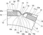
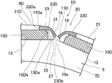
- Example 1 It is a principal part front view of a rotor.
- Example 1 It is a principal part front view of the rotor which shifted the rotation position.
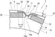
- Example 1 It is a principal part front view explaining a dimensional relationship.
- (Example 1) It is a principal part front view of a rotor.
- Example 1 It is a principal part front view of a rotor.
- Example 1 It is a principal part front view of a rotor.
- Example 1 It is a principal part front view of a rotor.
- Example 1 It is a principal part front view of a rotor.
- Example 1 It is a principal part front view of a rotor.
- Example 1 It is a principal part front view of a rotor.
- Example 1 It is a principal part front view of a rotor.
- Example 1 It is a principal part front view of a rotor.
- Example 1 It is a principal part front view of a rotor.
- Comparative example It is a principal part front view of a rotor.
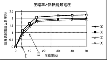
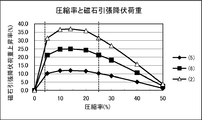
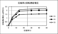
- Comparative example It is the graph which compared the yield example increase rate and the rotation induced voltage increase rate with the shape example of an Example, and the shape example of a comparative example. It is the graph which compared the relationship between the compression rate and the magnet tensile yield load increase rate in the shape example of the example and the shape example of the comparative example. It is the graph which compared the relationship between the compression rate and the rate of rotation-induced voltage increase between the shape example of the example and the shape example of the comparative example.
- the main body is formed in a circular shape and laminated inside the outer periphery
- a rotor of a motor in which a permanent magnet having a long cross section in the circumferential direction of the main body portion and a substantially rectangular permanent magnet is held in a plurality of magnet holding openings formed in a long length along the circumferential direction and arranged at predetermined intervals in the circumferential direction.
- a magnetic plate used for a core wherein a rotor radial width of a magnetic pole portion between an outer peripheral edge of the main body and the opening is set smaller than a radial cross-sectional width of the permanent magnet, and the opening Realized by setting a high-hardness part that has a relatively high yield stress so that it has a bowl shape along the end corner of the magnet and the maximum radial width is smaller than the radial cross-sectional width of the permanent magnet. did.
- the high hardness portion is a first edge along a circumferential direction located on an outer peripheral side of the main body at the circumferential end of the opening, and an edge continuous with the first edge, and the permanent magnet Between the second edge located on the circumferential edge side and the third edge on the outer peripheral edge side of the main body corresponding to the first edge and the fourth edge of the bridge part between the openings or the opening You may set to the range over.
- the high-hardness part is set by entering the magnetic pole part central side up to or beyond the boundary where the range in the circumferential direction of the main body part reaches the outer peripheral edge along the edge of the permanent magnet. Also good.
- the high hardness portion may be formed so that an end edge in a circumferential direction of the main body portion gradually enters the magnetic pole portion center side from the opening side toward the outer peripheral edge of the main body portion.
- the outer peripheral edge of the main body is provided with a concave shape portion that is gradually cut between the magnetic pole portions, and the high-hardness portion has the inclined end edge gradually cut into the concave shape portion. You may reach the outer periphery of the said main-body part at the starting point of such a shape.
- the high hardness portion is set to have a length between the openings equal to or more than 1/2 of a radial sectional width of the permanent magnet.
- the length that overlaps the permanent magnet at the edge portion along the opening in the circumferential direction of the main body is the length of the long side that contacts the magnetic pole along the rotor circumferential direction of the permanent magnet cross section (hereinafter referred to as permanent). 1/6 or less of the circumferential cross-sectional length of the magnet) is set to 0, and the high hardness portion is set to 1.3 to 2.3 times the Vickers hardness of the general portion hardness of the main body portion. May be.
- the high hardness portion may be compressed at a compression rate of 5 to 25% with respect to the plate thickness of the general portion of the main body portion.
- the high-hardness part may have a magnetic flux density at a magnetic field of 4000 A / m of 0.4 to 0.8 times that of the general part of the main body part.
- the main body portion to be laminated may be formed of a silicon steel plate.
- the silicon steel plate of the main body may have a composition (mass%) of Si: 2 to 4, balance: iron and inevitable impurities.
- the high hardness portion may have a hardness of 250 to 390 Hv.
- the main body may have a thickness of 0.1 to 0.5 mm.
- the main body may be arranged annularly by joining a plurality of divided bodies.
- the high hardness portion may be formed at both ends of the opening in the circumferential direction of the main body.
- FIG. 1 is a front view of the main part of the rotor (front with respect to the magnetic plate surface)
- FIG. 2 is a front view of the main part of the rotor with the rotational position shifted
- FIG. 3 is a front view of the main part for explaining the dimensional relationship. is there.
- FIG. 1 is used also for description of the evaluation method of the centrifugal strength described later, hatching of a fixed portion and an arrow of a load direction are described together.
- the rotor core 3 of the rotor 1 used in the electric motor is formed by laminating a plurality of magnetic plates 5.
- the main body portion 7 of each magnetic plate 5 is made of a high magnetic permeability material, such as a silicon steel plate, and is formed in a circular shape, for example, a disk shape or an annular shape.
- the silicon steel plate constituting the main body 7 has a composition (mass%) of Si: 2 to 4, the balance: iron and inevitable impurities.
- another material can also be used as a material of the magnetic plate 5.
- concave portions 11 are formed on the circular outer peripheral edge 9 at predetermined intervals in the circumferential direction.
- the concave portion 11 is formed in a shape that is gradually cut between the magnetic pole portions.
- the magnet slot 13 which is the opening part for magnet holding
- the magnet slots 13 are elongated along the tangential direction, which is the circumferential direction, and a plurality of magnet slots 13 are arranged at predetermined intervals in the circumferential direction.
- a permanent magnet 15 is held in each magnet slot 13 by an adhesive.
- a pair of permanent magnets can be held in each magnet slot 13.
- the permanent magnet 15 is formed in a substantially rectangular shape having a long cross section in the circumferential direction of the main body 7 and extends in the magnetic plate stacking direction.
- the permanent magnet 15 is held in the magnet slot 13 to be predetermined in the circumferential direction of the main body 7. Multiple arrays are arranged at intervals.
- the magnet slot 13 includes adhesive regions 17 on both sides of the region of the permanent magnet 15, the adhesive region 17 is adjacent to the bridge portion 19, and the bridge portion 19 is a recess in the outer peripheral edge 9 of the magnet slot 13 and the main body portion 7. It is located between the shape part 11.
- the pair of bridge portions 19 between the magnet slots 13 are integrated as a coupling portion 19 a on the inner end side between the magnet slots 13 in the radial direction of the main body portion 7.
- the radial width of the magnetic pole portion 21 between the outer peripheral edge 9 of the main body portion 7 and the magnet slot 13 is set to be smaller than the radial sectional width of the permanent magnet 15.
- the comparison between the radial width of the magnetic pole portion 21 and the radial cross-sectional width of the permanent magnet 15 is the dimension at the magnetic pole center that is the maximum width position of the magnetic pole portion 21.
- the main body portion 7 is provided with a high hardness portion 23 extending from the bridge portion 19 to the magnetic pole portion 21.
- the high hardness portions 23 are formed at both ends of the magnet slot 13 in the circumferential direction of the main body portion 7.
- the high hardness portion 23 has a bowl shape along the end corner 13 a of the magnet slot 13 and is formed so that the maximum width in the radial direction is smaller than the radial sectional width of the permanent magnet 15.
- the maximum width is formed to be smaller than the radial cross-sectional width of the permanent magnet 15 over the entire high hardness portion 23.
- only the maximum width in the radial direction of the high hardness portion 23 is formed to be smaller than the radial cross-sectional width of the permanent magnet 15, and the width between the magnet slots 13 of the high hardness portion 23 is the same as that of the permanent magnet 15. It can also be formed larger than the radial cross-sectional width.
- the high hardness portion 23 is set to a relatively high hardness with respect to a general portion other than the high hardness portion 23 of the main body portion 7 by compression processing.
- the high hardness portion 23 is formed by compression processing at a compression rate of 5 to 25% while the plate thickness of the general portion of the main body portion 7 is, for example, 0.1 to 0.5 mm.
- the high hardness portion 23 is set to 1.3 to 2.3 times the Vickers hardness with respect to the hardness of the general portion of the main body portion 7. Specifically, the hardness of the high hardness portion 23 is 250 to 390 Hv.
- the high hardness portion 23 has a magnetic flux density at a magnetic field of 4000 A / m of 0.4 to 0.8 times that of the general portion of the main body portion 7.
- the high hardness portion 23 is set in a range extending over the first edge 25 and the second edge 27, the third edge 29, and the fourth edge 31.
- the first edge 25 is a portion along the circumferential direction located on the outer peripheral side of the main body 7 at the circumferential end of the magnet slot 13.
- the second edge 27 is a portion of the bridge portion 19 that is located on the edge continuous with the first edge 25 and is located on the circumferential end edge 15 a side of the permanent magnet 15.
- the third edge 29 is a part on the outer peripheral edge 9 side of the main body portion 7 corresponding to the first edge 25.
- the fourth edge 31 is an outer portion of the bridge portion 19 between the magnet slots 13.
- the high hardness portion 23 in the range where the high hardness portion 23 is formed, it extends from the magnetic pole portion 21 to the bridge portion 19 and extends over the entire width.
- the formation range of the high hardness portion 23 may be partially formed in the width direction from the magnetic pole portion 21 to the bridge portion 19, and only one of the magnetic pole portion 21 or the bridge portion 19 is partially formed in the width direction. On the other hand, it can also be formed entirely in the width direction. Further, when the magnetic pole portion 21 and the bridge portion 19 are partially formed in the width direction, they can be formed only in the intermediate portion in the width direction as a core portion having high hardness.
- the high hardness portion 23 enters the center of the magnetic pole portion 21 beyond the boundary 33 (FIG. 3) where the range in the circumferential direction of the main body portion 7 extends to the outer peripheral edge 9 side along the edge 15 a of the permanent magnet 15. Is set.
- the outer peripheral edge 9 side is the third edge 29 of the concave-shaped part 11 and, as will be described later, the radially inner side of the main body part 7 with respect to the outer peripheral edge 9 (for example, the diameter relative to the rotor outer diameter line). (Inward direction).
- the high hardness portion 23 is formed so as to be inclined so that the edge 23a (FIG. 2) in the circumferential direction of the main body portion 7 gradually enters the magnetic pole portion 21 center side from the magnet slot 13 side toward the outer peripheral edge 9 of the main body portion 7. ing.
- An end edge 23 a formed by tilting the high hardness portion 23 reaches the outer peripheral edge 9 of the main body portion 7 at the start point 11 a of the concave portion 11.
- the starting point 11a is a point at the outer peripheral edge 9 where the concave shape portion 11 starts to be cut off from the circular outer peripheral edge 9 (for example, the rotor outer diameter line) gradually toward the inner diameter side.
- the end edge 23 b in the radial direction of the main body portion 7 is located at the boundary with the coupling portion 19 a, the end edges 23 b are inclined and face each other, and gradually toward the radially inner side of the main body portion 7.
- the interval is set to increase.
- the high-hardness portion 23 has a length L1 between the magnet slots 13 in the direction along the end edge 15 a of the permanent magnet 15, and the edge of the magnet slot 13 on the side along the circumferential direction of the main body portion 7.
- the length that overlaps with the permanent magnet 15 in the portion is L2.
- One end of L1 coincides with the edge of the permanent magnet 15 on the magnetic pole portion 21 side, and the other end is the tip of the end edge 23b in the direction along the end edge 15a.
- L1 is set to 1/2 or more of the radial sectional width of the permanent magnet 15, and L2 is set to 1/6 or less of the circumferential sectional length of the permanent magnet 15.
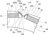
- FIG. 4 is a front view of the main part of the rotor corresponding to FIGS. 2 and 3.
- symbol is attached
- A is attached
- the edge 23Aa in the circumferential direction of the main body portion 7A of the high hardness portion 23A is located at the boundary 33A.
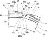
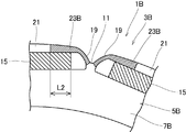
- FIG. 5 is a front view of a main part of the rotor corresponding to FIGS. 2 and 3.
- symbol is attached
- B is attached
- the range of the high hardness portion 23B in the circumferential direction of the main body portion 7B has a boundary 33B that reaches the outer peripheral edge 9B along the edge 15a of the permanent magnet 15. It is set so as to enter the center side of the magnetic pole part 21 beyond.
- the edge 23Ba of the high hardness portion 23B in the circumferential direction of the main body 7 is set in parallel with the boundary 33B.
- FIG. 6 is a front view of a main part of the rotor corresponding to FIGS. 2 and 3.
- symbol is attached
- C is attached
- the setting of the edge 23Cb of the high hardness portion 23C on the radially inner side of the main body portion 7C is changed with respect to the shape example 3.
- the edge 23Cb is located away from the coupling portion 19a in the radial direction of the main body 7C, and each edge 23Cb is substantially parallel to the edge 15a of the permanent magnet 15 and is set to face each other. Yes.
- FIG. 7 is a front view of the main part of the rotor corresponding to FIGS. 2 and 3.
- symbol is attached
- D is attached
- the high hardness portion 23D is common to the shape example 3, and the permanent magnet 15D has a chamfered portion 15Db.
- FIG. 8 is a front view of the main part of the rotor corresponding to FIGS. 2 and 3.
- symbol is attached
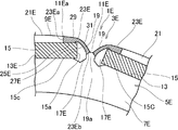
- the adhesive region 17E is enlarged so as to surround the end portion 15c of the permanent magnet 15 with respect to the shape example 3.
- FIG. 9 is a front view of the main part of the rotor corresponding to FIGS. 2 and 3.
- symbol is attached
- F is attached
- the high hardness portion 23F is set in a range extending over the first edge 25F, the second edge 27F, the third edge 29F, and the fourth edge 31F. Has been.
- the first edge 25F is a portion along the circumferential direction at the circumferential end of the magnet slot 13F.
- the second edge 27F is a portion of the bridge portion 19F on the same edge as the first edge 25F.
- the third edge 29F is a part on the outer peripheral edge 9F side of the main body portion 7F corresponding to the first edge 25F.
- the fourth edge 31F is a portion outside the bridge portion 19F between the magnet slots 13F.
- the third edge 29F is not the edge of the concave portion as in the shape example 1, but is a part of the outer peripheral edge 9F (on the rotor outer diameter line).
- the high hardness portion 23F has a bowl shape in which the first edge 25F and the second edge 27F are perpendicular to each other along the end portion 15Fc of the permanent magnet 15F.
- the edge 23Fa in the circumferential direction of the high hardness portion 23F is set in the same manner as in the shape example 3, but the edge 23Fb in the radial direction is set to enter the coupling portion 19Fa.
- the end edge 23Fb is along the circumferential direction of the main body 7F in the same manner as the long side of the permanent magnet 15F cross section.
- FIG. 10 is a front view of the main part of the rotor corresponding to FIGS. 2 and 3.
- symbol is attached
- the concave portion is not formed in the main body portion 7G, and the high-hardness portion 23G is the first in the circumferential direction at the circumferential end of the magnet slot 13G.
- the edge 25G and the third edge 29G on the outer peripheral edge 9G side of the main body portion 7G corresponding to the first edge 25G and the second edge 27G, which is a part of the bridge portion 19G on the same edge and the magnet slot 13G It is set to a range that spans and is T-shaped.
- the third edge 29G is continuous between the magnet slots 13G.
- the bridge portion 19G does not refer to the entire center of the T-shape, but the bridge portions 19G of the pair of high hardness portions 23G are integrated to form the center of the T-shape.
- the width in the direction is 1 ⁇ 2 of the circumferential width of the T-shaped part.
- FIG. 11 is a front view of the main part of the rotor corresponding to FIGS. 2 and 3 according to the first comparative example. Note that the structure is basically the same as that of the shape example 3, and only representative reference numerals are given in the same manner as the shape example 3.
- the edge length L2 along the magnet slot 13 in the circumferential direction of the main body portion 7B is set to exceed 1/6 of the circumferential sectional length of the permanent magnet 15. ing.
- FIG. 12 is a front view of a main part of a rotor corresponding to Comparative Example 2 and corresponding to FIGS. 2 and 3. Note that the structure is basically the same as that of the shape example 3, and only representative reference numerals are given in the same manner as the shape example 3.
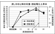
- FIG. 13 shows the rate of increase in the magnet tensile yield load as an alternative indicator of centrifugal strength and the alternative indicator of the effective magnetic flux amount, which is induced in a stator that does not supply power by rotating the rotor with power of a system different from the stator.
- FIG. 14 is a graph comparing the rate of increase in voltage (hereinafter referred to as rotation-induced voltage) between the shape example of the example and the shape example of the comparative example, and FIG. 14 shows an increase in the compression rate and magnet tensile yield load when machining the high hardness portion.
- rotation-induced voltage the rate of increase in voltage
- FIG. 15 is a graph in which the relationship between the compression ratio and the shape example of the comparative example is compared, and FIG. 15 illustrates the relationship between the compression ratio and the rate of increase of the rotation induced voltage in the shape example of the embodiment and the shape example of the comparative example. It is the graph compared with.
- the centrifugal strength was evaluated as shown in FIG.
- the effect of improving the centrifugal strength is to fix the yoke portion 7a on the inner diameter side of the magnet slot 13 in FIG. 1 within the hatched range and insert a jig simulating the permanent magnet 15 into the opening.
- the amount of effective magnetic flux caused by the torque generated by the motor was evaluated by the magnitude of the rotation-induced voltage serving as an alternative index.
- the horizontal axis is the shape examples (1) to (4), and the vertical axis is the magnet tensile yield load increase rate% and the rotation induced voltage increase rate%.
- Examples of shapes are: (1): Example 2 of Example 1, (2): Example 3 of Example 1, (3): Example 1 of Example 1, (4): Example of Comparative Example 1 Was selected. The compression ratio of the high hardness portion 23 was 14%.
- the corresponding part is compressed, but for that purpose, a compressive load is required.
- the area of the high hardness portion is (1) ⁇ (2) ⁇ (3) ⁇ (4). If the compression rate is the same, the larger the area, the greater the compression load.
- the increase rate is the maximum in (3) for both the magnet tensile yield load and the rotation-induced voltage. If the area is larger than that, the increase rate decreases and the machining energy becomes inefficient (high cost).
- the horizontal axis represents the compression rate
- the vertical axis represents the magnet tensile yield load increase rate%.
- the rate of increase is 20% or more, which is a market requirement, from a compression rate of 5%.
- the compression rate indicated by arrow III is 25% or more, the increase rate of the yield load is lower than the compression rate of 5%, and the compression processing energy (manufacturing cost) is inefficient, so the upper limit of the compression rate is 25% as described above. .
- the horizontal axis represents the compression rate
- the vertical axis represents the rate of increase in rotation-induced voltage.
- the selected shape example is the same as FIG.
- the compression rate of the arrow I is 5% or more to satisfy the magnet tensile yield load requirement, but the rotation induced voltage increase rate is less than the required 1% (arrow II) and is outside the allowable range. . If the rotation induced voltage, which is an alternative index of the effective magnetic flux amount, does not increase by 1% or more due to the reduction of the leakage magnetic flux, it cannot be recognized as an effective performance.
- the shape examples 2, 3, and 1 of the embodiments (1) to (3) are all within the allowable range.
- FIG. 16 is a graph comparing the relationship between the compression rate and the magnet tensile yield load increase rate between the shape example of the example and the shape example of the comparative example, and FIG. 17 shows the relationship between the compression rate and the rotation induced voltage increase rate. It is the graph compared with the shape example and the comparative example.
- the horizontal axis represents the compression rate
- the vertical axis represents the magnet tensile yield load increase rate%.
- the yield load increase rate of the high hardness portion 23B of Comparative Example 2 does not reach 20%, whereas in Shape Example 4 and Shape Example 3 of Example 1, the increase rate is 20% or more. It was.
- the horizontal axis represents the compression rate
- the vertical axis represents the rate of increase of the rotation-induced voltage.
- the increase rate of the induced voltage of the high hardness portion 23B of Comparative Example 2 does not reach 1%, whereas in the shape example 4 and the shape example 3 of Example 1, the increase rate is 5 to 25%. More than 1%.
- Comparative Example 2 is eliminated in terms of the yield load increase rate and the induced voltage increase rate, and the above-described setting of L1 ⁇ 1/2 is achieved in terms of performance.
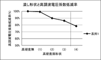
- HVF harmonic voltage coefficient
- the horizontal axis represents shape examples (1) to (4), and the vertical axis represents HVF reduction rate%.
- the shape examples are as follows: (1): Shape example 2 of Example 1, (2): Shape example 3 of Example 1, (3): Shape example 1 of Example 1, (4): Comparative example 1
- the shape example was selected, and the compression ratio of the high hardness portion 23 was 14%. In order to achieve high hardness, the corresponding portion is compressed, but for that purpose, a compressive load is required.
- the area of the high hardness portion is (1) ⁇ (2) ⁇ (3) ⁇ (4). If the compression rate is the same, the larger the area, the greater the compression load.
- the harmonic voltage coefficient decreases as the area increases.
- the horizontal axis represents the compression rate and the vertical axis represents the HVF reduction rate%.
- the selected shape example is the same as the previous figure. In the same shape, when the compression ratio range of the high hardness portion is 5 to 25%, the harmonic voltage coefficient is reduced with respect to that without the high hardness portion.
- the HVF varies depending on the range of the high hardness portion on the magnetic pole portion 21 side, but is applied to the HVF in the range of the high hardness portion on the bridge portion 19 side.
- the influence is slight, and the high hardness part on the bridge part 19 side is sufficient within the scope of the present invention. Therefore, the harmonics contained in the magnetic flux distribution generated on the outer peripheral surface of the rotor by the permanent magnet 15 in the shape examples 1 to 8 can be reduced, and the iron loss can be suppressed.
- the high hardness portion 23 is formed on the main body portion 7 by compressing a predetermined portion to be the high hardness portion 23 before the contour of the main body portion 7 is formed from a plate material.
- the high hardness portion 23 can be formed after the contour of the main body portion 7 is formed.
- the main body 7 can also be applied to a structure in which a plurality of divided bodies are joined and arranged in an annular shape.
- a plurality of main body portions 7 are formed in a circular shape, stacked and formed in a long shape along the circumferential direction inside the outer peripheral edge 9, and a plurality of magnets are arranged at predetermined intervals in the circumferential direction.
- the magnetic plate 5 is used for a rotor core of a motor in which a permanent magnet having a long cross section in the circumferential direction of the main body 7 is held in the magnet slot 13 of the motor, and the outer peripheral edge 9 of the main body 7 and the magnet slot 13 is set to be smaller than the radial cross-sectional width of the permanent magnet 15, and has a saddle shape along the end corner of the magnet slot 13.
- the high hardness part 23 relative to the general part with a smaller width was set.
- the width of the magnetic pole portion 21 can be set smaller than the radial cross-sectional width of the permanent magnet 15 to reduce the magnetic resistance of the magnetic pole portion 21 and increase the magnetic flux effective for rotor rotation.
- the ineffective magnetic flux that does not contribute to the rotor rotational torque in the bridge portion 19 around the end corner of the magnet slot 13 can be suppressed and activated.
- the width of the high-hardness portion 23 is smaller than the radial cross-sectional width of the permanent magnet 15, and the invalid magnetic flux can be more reliably suppressed and validated.
- the magnet slot is not limited to a strictly rectangular shape, and may be, for example, a somewhat arc shape concentrically with the rotor, and the arrangement and number of magnet slots may be appropriately selected according to the use of the electric motor. Become.
Landscapes
- Engineering & Computer Science (AREA)
- Power Engineering (AREA)
- Manufacturing & Machinery (AREA)
- Permanent Field Magnets Of Synchronous Machinery (AREA)
Abstract
Description
ように相対的に降伏応力が高い高硬度部を設定したことにより実現した。
図1は、ロータの要部正面図(磁性板面に対して正面)、図2は、回転位置をずらしたロータの要部正面図、図3は、寸法関係を説明する要部正面図である。なお、図1は、後述する遠心強度の評価方法の説明にも用いるため、固定箇所のハッチング及び荷重方向の矢印が併せて記載されている。
図4は、図2、図3に相当するロータの要部正面図である。なお、形状例1と同一構成部分には同符号を付し、対応する構成部分には、同符号にAを付し、重複した説明は省略する。
図5は、図2、図3に相当するロータの要部正面図である。なお、形状例1と同一構成部分には同符号を付し、対応する構成部分には、同符号にBを付し、重複した説明は省略する。
図6は、図2、図3に相当するロータの要部正面図である。なお、形状例1と同一構成部分には同符号を付し、対応する構成部分には、同符号にCを付し、重複した説明は省略する。
図7は、図2、図3に相当するロータの要部正面図である。なお、形状例1と同一構成部分には同符号を付し、対応する構成部分には、同符号にDを付し、重複した説明は省略する。
図8は、図2、図3に相当するロータの要部正面図である。なお、形状例1と同一構成部分には同符号を付し、対応する構成部分には、同符号にEを付し、重複した説明は省略する。
図9は、図2、図3に相当するロータの要部正面図である。なお、形状例1と同一構成部分には同符号を付し、対応する構成部分には、同符号にFを付し、重複した説明は省略する。
図10は、図2、図3に相当するロータの要部正面図である。なお、形状例1と同一構成部分には同符号を付し、対応する構成部分には、同符号にGを付し、重複した説明は省略する。
図11は、比較例1に係り、図2、図3に相当するロータの要部正面図である。なお、形状例3と基本的には同一構造であり、代表的な符号のみを形状例3と同一に付す。
図12は、比較例2に係り、図2、図3に相当するロータの要部正面図である。なお、形状例3と基本的には同一構造であり、代表的な符号のみを形状例3と同一に付す。
(0≦L2≦1/6)
図13は、遠心強度の代替指標とした磁石引張降伏荷重の上昇率及び有効磁束量の代替指標とした、ロータをステータとは別系統の動力で回転させ、電力を供給しないステータに誘起される電圧(以下、回転誘起電圧という)の上昇率を実施例の形状例と比較例の形状例とで比較したグラフ、図14は、高硬度部を加工する際の圧縮率と磁石引張降伏荷重上昇率との関係を実施例の形状例と比較例の形状例とで比較したグラフ、図15は、同圧縮率と回転誘起電圧上昇率との関係を実施例の形状例と比較例の形状例とで比較したグラフである。
認められない。
図16は、圧縮率と磁石引張降伏荷重上昇率との関係を実施例の形状例と比較例の形状例とで比較したグラフ、図17は、圧縮率と回転誘起電圧上昇率との関係を形状例と比較例とで比較したグラフである。
回転誘起電圧には高調波が含まれているが、その含有率を表す指標として、高調波電圧係数(以下、HVFという)を導入して評価した。HVFは式1の通りである。


形状例1について、図1のように、永久磁石15断面長辺の外周側をN極、内周側をS極とする永久磁石15等を埋設した場合、ブリッジ部19等から磁極部21側へ高硬度部23等が形成されると、この部分での磁気特性の低下を図ることができる。このため、磁束は主に永久磁石15断面長辺の垂直方向即ち磁極部におけるロータ径方向に多く発生し、ブリッジ部19側における無効な磁束を少なくし、ロータ回転に有効となる磁束をより多くすることができる。
形状例1について、本体部7に対する高硬度部23の形成は、本体部7の輪郭を板材から形成する前に高硬度部23となる予定箇所を圧縮加工して予め形成する。
本体部7は、複数の分割体を接合して環状に配置形成するものにも適用することができる。
本発明の実施例1では、本体部7が周回形状に形成されて複数枚積層され外周縁9の内側で周方向に沿って長尺に形成され周方向に所定間隔で複数配列した磁石保持用の磁石スロット13に本体部7の周方向へ断面が長尺でほぼ矩形の永久磁石を保持させたモータのロータ・コアに用いる磁性板5であって、本体部7の外周縁9と磁石スロット13との間の磁極部21の径方向幅を、永久磁石15の径方向断面幅よりも小さく設定し、磁石スロット13の端部コーナに沿って鉤状をなし永久磁石15の径方向断面幅よりも小さな幅で一般部に対する相対的な高硬度部23を設定した。
[その他]
なお、磁石スロットは厳密な矩形に限定されるものではなく、例えばロータと同心円上の多少円弧状のものでもよく、また磁石スロットの配置や数も電動モータの用途に応じて適宜選択することになる。
3,3A,3B,3C,3D,3E,3F,3G ロータ・コア
5,5A,5B,5C,5D,5E,5F,5G 磁性板
7,7A,7B,7C,7D,7E,7F,7G 本体部
9,9A,9B,9C,9D,9E,9F,9G 外周縁
11,11A,11B,11C,11D,11E,11F 凹形状部
13,13E,13F,13G 磁石スロット(開口部)
15,15D,15F,15G 永久磁石
15a,15Da,15Fa,15Ga 端縁
19,19F,19G ブリッジ部
21,21A,21B,21B,21C,21D,21E,21F,21G 磁極部
23,23A,23B,23C,23D,23E,23F,23G 高硬度部
23a,23Aa,23Ba,23Ca,23Da,23Ea,23Fa,23Ga 端縁
23b,23Ab,23Bb,23Cb,23Db,23Eb,23Fb,23Gb 端縁
25,25E,25F,25G 第1の縁
27,27E,27F,27G 第2の縁
29,29F,29G 第3の縁
31,31F,31G 第4の縁
33,33A,33B 境界
Claims (11)
- 本体部が周回形状に形成されて複数枚積層され外周縁の内側で周方向に沿って長尺に形成され周方向に所定間隔で複数配列した磁石保持用の開口部に、断面が前記本体部の周方向へ長尺のほぼ矩形の永久磁石を保持させたモータのロータ・コアに用いる磁性板であって、
前記本体部の外周縁と前記開口部との間の磁極部の径方向幅を、前記永久磁石の径方向断面幅よりも小さく設定し、
前記開口部の端部コーナに沿って鉤状をなし、径方向における最大幅が前記永久磁石の径方向断面幅よりも小さな幅となるように相対的な高硬度部を設定した、
ことを特徴とするモータのロータ・コアに用いる磁性板。 - 請求項1記載のモータのロータ・コアに用いる磁性板であって、
前記高硬度部は、前記開口部の周方向端部で前記本体部の外周側に位置する周方向に沿った第1の縁及び第1の縁と連続する縁辺上であって前記永久磁石の周方向端縁側に位置する第2の縁と前記第1の縁に対応する前記本体部の外周縁側の第3の縁及び前記開口部相互間のブリッジ部の第4の縁又は前記開口部間とに渡る範囲に設定した、
ことを特徴とするモータのロータ・コアに用いる磁性板。 - 請求項1又は2記載のモータのロータ・コアに用いる磁性板であって、
前記高硬度部は、前記本体部の周方向での範囲が前記永久磁石の端縁に沿って前記外周縁にまで至る境界までか該境界を超えて前記磁極部中央側に入り込んで設定された、
ことを特徴とするモータのロータ・コアに用いる磁性板。 - 請求項1~3の何れか1項記載のモータのロータ・コアに用いる磁性板であって、
前記高硬度部は、前記本体部の周方向での端縁が前記開口部側から前記本体部の外周縁に向かって前記磁極部中央側へ漸次入り込むように傾斜形成された、
ことを特徴とするモータのロータ・コアに用いる磁性板。 - 請求項1~4の何れか1項記載のモータのロータ・コアに用いる磁性板であって、
前記本体部の外周縁に、前記磁極部間へ漸次切り込まれるような形態の凹形状部を備えた、
ことを特徴とするモータのロータ・コアに用いる磁性板。 - 請求項5記載のモータのロータ・コアに用いる磁性板であって、
前記高硬度部は、前記傾斜形成された端縁が前記凹形状部の漸次切り込まれるような形状の開始点で前記本体部の外周縁に至っている、
ことを特徴とするモータのロータ・コアに用いる磁性板。 - 請求項1~6の何れか1項記載のモータのロータ・コアに用いる磁性板であって、
前記高硬度部は、前記永久磁石の端縁に沿った方向及び前記開口部間での長さが前記永久磁石の径方向断面幅の1/2以上に設定され、
前記高硬度部は、前記本体部の周方向で前記開口部に沿った縁の部分で前記永久磁石とオーバーラップする長さが前記永久磁石の周方向断面長さの1/6以下から0の間に設定されている、
ことを特徴とするモータのロータ・コアに用いる磁性板。 - 請求項1~7の何れか1項記載のモータのロータ・コアに用いる磁性板であって、
前記高硬度部は、磁場4000A/mにおける磁束密度が前記本体部の一般部に対し0.4~0.8倍である、
ことを特徴とするモータのロータ・コアに用いる磁性板。 - 請求項1~8の何れか1項記載のモータのロータ・コアに用いる磁性板であって、
前記本体部は、厚みが0.1~0.5mmである、
ことを特徴とするモータのロータ・コアに用いる磁性板。 - 請求項1~9の何れか1項記載のモータのロータ・コアに用いる磁性板であって、
前記本体部は、複数の分割体を接合して環状に配置した、
ことを特徴とするモータのロータ・コアに用いる磁性板。 - 請求項1~10の何れか1項記載のモータのロータ・コアに用いる磁性板の製造方法であって、
前記高硬度部は、前記本体部の輪郭を板材から形成する前に前記高硬度部となる予定箇所を圧縮加工して予め形成する、
ことを特徴とするモータのロータ・コアに用いる磁性板の製造方法。
Priority Applications (4)
| Application Number | Priority Date | Filing Date | Title |
|---|---|---|---|
| EP14784870.9A EP2988395A4 (en) | 2013-04-16 | 2014-04-15 | Magnetic plate used for rotor core of motor and method for manufacturing magnetic plate |
| US14/785,168 US9570948B2 (en) | 2013-04-16 | 2014-04-15 | Magnetic plate used for rotor core of motor and method for manufacturing magnetic plate |
| CN201480021179.7A CN105164896B (zh) | 2013-04-16 | 2014-04-15 | 用于马达的转子铁芯的磁性板及其制造方法 |
| JP2015512308A JP5855792B2 (ja) | 2013-04-16 | 2014-04-15 | モータのロータ・コアに用いる磁性板及びその製造方法 |
Applications Claiming Priority (2)
| Application Number | Priority Date | Filing Date | Title |
|---|---|---|---|
| JP2013086140 | 2013-04-16 | ||
| JP2013-086140 | 2013-04-16 |
Publications (1)
| Publication Number | Publication Date |
|---|---|
| WO2014171133A1 true WO2014171133A1 (ja) | 2014-10-23 |
Family
ID=51731096
Family Applications (1)
| Application Number | Title | Priority Date | Filing Date |
|---|---|---|---|
| PCT/JP2014/002135 Ceased WO2014171133A1 (ja) | 2013-04-16 | 2014-04-15 | モータのロータ・コアに用いる磁性板及びその製造方法 |
Country Status (5)
| Country | Link |
|---|---|
| US (1) | US9570948B2 (ja) |
| EP (1) | EP2988395A4 (ja) |
| JP (1) | JP5855792B2 (ja) |
| CN (1) | CN105164896B (ja) |
| WO (1) | WO2014171133A1 (ja) |
Cited By (2)
| Publication number | Priority date | Publication date | Assignee | Title |
|---|---|---|---|---|
| DE112017001847T5 (de) | 2016-06-03 | 2018-12-27 | Aisin Aw Co., Ltd. | Rotor |
| WO2021145119A1 (ja) * | 2020-01-14 | 2021-07-22 | 日立Astemo株式会社 | 回転電機、及び車載電動機システム |
Families Citing this family (9)
| Publication number | Priority date | Publication date | Assignee | Title |
|---|---|---|---|---|
| WO2015189938A1 (ja) * | 2014-06-11 | 2015-12-17 | 三菱電機株式会社 | 永久磁石埋込型電動機 |
| DE102017103619A1 (de) * | 2017-02-22 | 2018-08-23 | Ebm-Papst St. Georgen Gmbh & Co. Kg | Elektromotor, Innenrotor und Rotorblech |
| WO2018203364A1 (ja) * | 2017-05-01 | 2018-11-08 | 三菱電機株式会社 | ロータ、電動機、圧縮機および空気調和装置 |
| CN111418132A (zh) * | 2017-12-07 | 2020-07-14 | 三菱电机株式会社 | 转子、电动机、压缩机、空气调节机以及转子的制造方法 |
| CN110620482B (zh) * | 2018-06-19 | 2021-08-31 | 丰田自动车株式会社 | 磁体埋入型电机及其制造方法 |
| JP7266495B2 (ja) * | 2019-08-21 | 2023-04-28 | 日本製鉄株式会社 | モータ |
| JP7283447B2 (ja) * | 2020-06-11 | 2023-05-30 | トヨタ自動車株式会社 | ロータの製造方法およびロータ製造装置 |
| JP7338570B2 (ja) * | 2020-07-01 | 2023-09-05 | トヨタ自動車株式会社 | 回転機のロータおよびその製造方法 |
| WO2023157131A1 (ja) * | 2022-02-16 | 2023-08-24 | 三菱電機株式会社 | 永久磁石回転子および永久磁石回転子の製造方法 |
Citations (7)
| Publication number | Priority date | Publication date | Assignee | Title |
|---|---|---|---|---|
| JP2003304670A (ja) | 2002-04-09 | 2003-10-24 | Toyota Motor Corp | 回転機用ロータの製造方法 |
| JP2004007943A (ja) | 2002-04-25 | 2004-01-08 | Nissan Motor Co Ltd | 回転子コア用の電磁鋼板形成体、これを用いた永久磁石内蔵型回転電機用回転子、永久磁石内蔵型回転電機、および回転子コア用の電磁鋼板形成体の製造方法 |
| WO2007080888A1 (ja) * | 2006-01-10 | 2007-07-19 | Mitsuba Corporation | 回転電機 |
| JP2009268328A (ja) * | 2008-04-30 | 2009-11-12 | Meidensha Corp | 永久磁石形同期回転電機の磁石固定構造 |
| JP2010016961A (ja) * | 2008-07-02 | 2010-01-21 | Mitsubishi Electric Corp | 永久磁石埋め込み型モータのロータ及びその製造方法 |
| JP2012105410A (ja) | 2010-11-09 | 2012-05-31 | Mitsubishi Electric Corp | 電動機及び圧縮機 |
| JP2012205429A (ja) * | 2011-03-25 | 2012-10-22 | Asmo Co Ltd | ロータ、及びモータ |
Family Cites Families (14)
| Publication number | Priority date | Publication date | Assignee | Title |
|---|---|---|---|---|
| US4434546A (en) * | 1979-09-21 | 1984-03-06 | General Electric Company | Method of making a core |
| US4570333A (en) * | 1983-10-28 | 1986-02-18 | General Electric Company | Method of making a permanent magnet rotor |
| JPH08331784A (ja) * | 1995-03-24 | 1996-12-13 | Hitachi Metals Ltd | 永久磁石界磁方式回転機 |
| JP3308828B2 (ja) * | 1996-10-18 | 2002-07-29 | 株式会社日立製作所 | 永久磁石回転電機及びそれを用いた電動車両 |
| US6332932B1 (en) * | 1999-04-20 | 2001-12-25 | Sumitomo Special Metals Co., Ltd. | Punch, powder pressing apparatus and powder pressing method |
| CN1102670C (zh) * | 1999-06-16 | 2003-03-05 | 住友金属工业株式会社 | 无方向性电磁钢片及其制造方法 |
| JP2001218400A (ja) * | 2000-02-07 | 2001-08-10 | Shinko Electric Co Ltd | 永久磁石式高速回転機 |
| DE10108192A1 (de) * | 2001-02-21 | 2002-08-29 | Bosch Gmbh Robert | Werkstück |
| JP4692428B2 (ja) * | 2006-07-21 | 2011-06-01 | 株式会社デンソー | 車両用回転電機の回転子とその製造方法 |
| JP5493675B2 (ja) * | 2009-02-09 | 2014-05-14 | 株式会社ジェイテクト | 電動モータおよびロータ |
| JP5292271B2 (ja) * | 2009-12-24 | 2013-09-18 | 株式会社日立製作所 | 永久磁石式回転電機 |
| US8310126B1 (en) * | 2011-10-27 | 2012-11-13 | Motor Patent Licensors, LLC | Radial flux permanent magnet AC motor/generator |
| HUE054387T2 (hu) * | 2011-11-29 | 2021-09-28 | Sumitomo Bakelite Co | Gyantakompozíció rögzítés céljára, rotor, személygépkocsi, és eljárás rotor elõállítására |
| JP2015012679A (ja) * | 2013-06-28 | 2015-01-19 | 株式会社日立製作所 | アキシャルギャップ型回転電機 |
-
2014
- 2014-04-15 EP EP14784870.9A patent/EP2988395A4/en not_active Withdrawn
- 2014-04-15 WO PCT/JP2014/002135 patent/WO2014171133A1/ja not_active Ceased
- 2014-04-15 CN CN201480021179.7A patent/CN105164896B/zh not_active Expired - Fee Related
- 2014-04-15 US US14/785,168 patent/US9570948B2/en not_active Expired - Fee Related
- 2014-04-15 JP JP2015512308A patent/JP5855792B2/ja not_active Expired - Fee Related
Patent Citations (7)
| Publication number | Priority date | Publication date | Assignee | Title |
|---|---|---|---|---|
| JP2003304670A (ja) | 2002-04-09 | 2003-10-24 | Toyota Motor Corp | 回転機用ロータの製造方法 |
| JP2004007943A (ja) | 2002-04-25 | 2004-01-08 | Nissan Motor Co Ltd | 回転子コア用の電磁鋼板形成体、これを用いた永久磁石内蔵型回転電機用回転子、永久磁石内蔵型回転電機、および回転子コア用の電磁鋼板形成体の製造方法 |
| WO2007080888A1 (ja) * | 2006-01-10 | 2007-07-19 | Mitsuba Corporation | 回転電機 |
| JP2009268328A (ja) * | 2008-04-30 | 2009-11-12 | Meidensha Corp | 永久磁石形同期回転電機の磁石固定構造 |
| JP2010016961A (ja) * | 2008-07-02 | 2010-01-21 | Mitsubishi Electric Corp | 永久磁石埋め込み型モータのロータ及びその製造方法 |
| JP2012105410A (ja) | 2010-11-09 | 2012-05-31 | Mitsubishi Electric Corp | 電動機及び圧縮機 |
| JP2012205429A (ja) * | 2011-03-25 | 2012-10-22 | Asmo Co Ltd | ロータ、及びモータ |
Non-Patent Citations (1)
| Title |
|---|
| See also references of EP2988395A4 * |
Cited By (5)
| Publication number | Priority date | Publication date | Assignee | Title |
|---|---|---|---|---|
| DE112017001847T5 (de) | 2016-06-03 | 2018-12-27 | Aisin Aw Co., Ltd. | Rotor |
| WO2021145119A1 (ja) * | 2020-01-14 | 2021-07-22 | 日立Astemo株式会社 | 回転電機、及び車載電動機システム |
| JP2021112076A (ja) * | 2020-01-14 | 2021-08-02 | 日立Astemo株式会社 | 回転電機、及び車載電動機システム |
| JP7348086B2 (ja) | 2020-01-14 | 2023-09-20 | 日立Astemo株式会社 | 回転電機、及び車載電動機システム |
| US12107470B2 (en) | 2020-01-14 | 2024-10-01 | Hitachi Astemo, Ltd. | Rotary electric machine and in-vehicle motor system |
Also Published As
| Publication number | Publication date |
|---|---|
| EP2988395A4 (en) | 2017-03-22 |
| EP2988395A1 (en) | 2016-02-24 |
| JPWO2014171133A1 (ja) | 2017-02-16 |
| US9570948B2 (en) | 2017-02-14 |
| US20160065015A1 (en) | 2016-03-03 |
| JP5855792B2 (ja) | 2016-02-09 |
| CN105164896B (zh) | 2017-08-18 |
| CN105164896A (zh) | 2015-12-16 |
Similar Documents
| Publication | Publication Date | Title |
|---|---|---|
| JP5855792B2 (ja) | モータのロータ・コアに用いる磁性板及びその製造方法 | |
| JP7337973B2 (ja) | 同期リラクタンス機械及び、同期リラクタンス機械を製造する方法 | |
| TW501327B (en) | Electrical machine stator and rotor | |
| CN101461119B (zh) | 分割型定子铁心及其制造方法、定子铁心 | |
| CN113346643B (zh) | 一种永磁电机 | |
| EP1865587B1 (en) | Magnetic powder metal composite core for electrical machines | |
| CN113346652B (zh) | 一种永磁电机 | |
| JP5623498B2 (ja) | 固定子鉄心及び固定子及び電動機及び圧縮機 | |
| CN105027391A (zh) | 永久磁铁埋入型电动机及其制造方法 | |
| CN101128969B (zh) | 磁性体、转子及电动机 | |
| JP2007074841A (ja) | ステータコア、それを用いたモータ及びその製造方法 | |
| JP5493792B2 (ja) | Ipmモータ用ロータとipmモータ | |
| CN203896058U (zh) | 永磁式旋转电机及电梯驱动提升机 | |
| JP5042184B2 (ja) | 同期電動機の回転子及び同期電動機の回転子の製造方法 | |
| JP2010045870A (ja) | 回転機 | |
| WO2021064883A1 (ja) | 回転電機 | |
| JP5471653B2 (ja) | 永久磁石式電動モータ | |
| JP2010045872A (ja) | 永久磁石式回転機 | |
| JP2014103824A (ja) | かご形誘導電動機 | |
| CN104079083A (zh) | 内转式定子 | |
| JP4694253B2 (ja) | 永久磁石式回転電機 | |
| JP2010142000A (ja) | ステータコア,ステータおよびアキシャル型モータ | |
| JP5782929B2 (ja) | モータのステータコア | |
| JP2006174525A (ja) | コア、電機子コア及びモータ | |
| JP6337549B2 (ja) | 磁石埋込型ロータ |
Legal Events
| Date | Code | Title | Description |
|---|---|---|---|
| WWE | Wipo information: entry into national phase |
Ref document number: 201480021179.7 Country of ref document: CN |
|
| 121 | Ep: the epo has been informed by wipo that ep was designated in this application |
Ref document number: 14784870 Country of ref document: EP Kind code of ref document: A1 |
|
| ENP | Entry into the national phase |
Ref document number: 2015512308 Country of ref document: JP Kind code of ref document: A |
|
| NENP | Non-entry into the national phase |
Ref country code: DE |
|
| WWE | Wipo information: entry into national phase |
Ref document number: 14785168 Country of ref document: US |
|
| WWE | Wipo information: entry into national phase |
Ref document number: 2014784870 Country of ref document: EP |