WO2014171179A1 - Dispositif et procédé de traitement d'informations et dispositif d'imagerie - Google Patents
Dispositif et procédé de traitement d'informations et dispositif d'imagerie Download PDFInfo
- Publication number
- WO2014171179A1 WO2014171179A1 PCT/JP2014/054077 JP2014054077W WO2014171179A1 WO 2014171179 A1 WO2014171179 A1 WO 2014171179A1 JP 2014054077 W JP2014054077 W JP 2014054077W WO 2014171179 A1 WO2014171179 A1 WO 2014171179A1
- Authority
- WO
- WIPO (PCT)
- Prior art keywords
- unit
- display
- display unit
- imaging
- displayed
- Prior art date
- Legal status (The legal status is an assumption and is not a legal conclusion. Google has not performed a legal analysis and makes no representation as to the accuracy of the status listed.)
- Ceased
Links
Images







Classifications
-
- G—PHYSICS
- G09—EDUCATION; CRYPTOGRAPHY; DISPLAY; ADVERTISING; SEALS
- G09G—ARRANGEMENTS OR CIRCUITS FOR CONTROL OF INDICATING DEVICES USING STATIC MEANS TO PRESENT VARIABLE INFORMATION
- G09G3/00—Control arrangements or circuits, of interest only in connection with visual indicators other than cathode-ray tubes
- G09G3/001—Control arrangements or circuits, of interest only in connection with visual indicators other than cathode-ray tubes using specific devices not provided for in groups G09G3/02 - G09G3/36, e.g. using an intermediate record carrier such as a film slide; Projection systems; Display of non-alphanumerical information, solely or in combination with alphanumerical information, e.g. digital display on projected diapositive as background
- G09G3/002—Control arrangements or circuits, of interest only in connection with visual indicators other than cathode-ray tubes using specific devices not provided for in groups G09G3/02 - G09G3/36, e.g. using an intermediate record carrier such as a film slide; Projection systems; Display of non-alphanumerical information, solely or in combination with alphanumerical information, e.g. digital display on projected diapositive as background to project the image of a two-dimensional display, such as an array of light emitting or modulating elements or a CRT
-
- G—PHYSICS
- G06—COMPUTING OR CALCULATING; COUNTING
- G06F—ELECTRIC DIGITAL DATA PROCESSING
- G06F1/00—Details not covered by groups G06F3/00 - G06F13/00 and G06F21/00
- G06F1/16—Constructional details or arrangements
- G06F1/1613—Constructional details or arrangements for portable computers
- G06F1/1633—Constructional details or arrangements of portable computers not specific to the type of enclosures covered by groups G06F1/1615 - G06F1/1626
- G06F1/1637—Details related to the display arrangement, including those related to the mounting of the display in the housing
- G06F1/1652—Details related to the display arrangement, including those related to the mounting of the display in the housing the display being flexible, e.g. mimicking a sheet of paper, or rollable
-
- G—PHYSICS
- G09—EDUCATION; CRYPTOGRAPHY; DISPLAY; ADVERTISING; SEALS
- G09G—ARRANGEMENTS OR CIRCUITS FOR CONTROL OF INDICATING DEVICES USING STATIC MEANS TO PRESENT VARIABLE INFORMATION
- G09G3/00—Control arrangements or circuits, of interest only in connection with visual indicators other than cathode-ray tubes
- G09G3/001—Control arrangements or circuits, of interest only in connection with visual indicators other than cathode-ray tubes using specific devices not provided for in groups G09G3/02 - G09G3/36, e.g. using an intermediate record carrier such as a film slide; Projection systems; Display of non-alphanumerical information, solely or in combination with alphanumerical information, e.g. digital display on projected diapositive as background
- G09G3/003—Control arrangements or circuits, of interest only in connection with visual indicators other than cathode-ray tubes using specific devices not provided for in groups G09G3/02 - G09G3/36, e.g. using an intermediate record carrier such as a film slide; Projection systems; Display of non-alphanumerical information, solely or in combination with alphanumerical information, e.g. digital display on projected diapositive as background to produce spatial visual effects
-
- H—ELECTRICITY
- H04—ELECTRIC COMMUNICATION TECHNIQUE
- H04M—TELEPHONIC COMMUNICATION
- H04M1/00—Substation equipment, e.g. for use by subscribers
- H04M1/02—Constructional features of telephone sets
- H04M1/0202—Portable telephone sets, e.g. cordless phones, mobile phones or bar type handsets
- H04M1/026—Details of the structure or mounting of specific components
- H04M1/0266—Details of the structure or mounting of specific components for a display module assembly
- H04M1/0268—Details of the structure or mounting of specific components for a display module assembly including a flexible display panel
-
- H—ELECTRICITY
- H04—ELECTRIC COMMUNICATION TECHNIQUE
- H04N—PICTORIAL COMMUNICATION, e.g. TELEVISION
- H04N23/00—Cameras or camera modules comprising electronic image sensors; Control thereof
- H04N23/50—Constructional details
- H04N23/53—Constructional details of electronic viewfinders, e.g. rotatable or detachable
-
- H—ELECTRICITY
- H04—ELECTRIC COMMUNICATION TECHNIQUE
- H04N—PICTORIAL COMMUNICATION, e.g. TELEVISION
- H04N23/00—Cameras or camera modules comprising electronic image sensors; Control thereof
- H04N23/60—Control of cameras or camera modules
- H04N23/62—Control of parameters via user interfaces
-
- H—ELECTRICITY
- H04—ELECTRIC COMMUNICATION TECHNIQUE
- H04N—PICTORIAL COMMUNICATION, e.g. TELEVISION
- H04N23/00—Cameras or camera modules comprising electronic image sensors; Control thereof
- H04N23/60—Control of cameras or camera modules
- H04N23/63—Control of cameras or camera modules by using electronic viewfinders
-
- H—ELECTRICITY
- H04—ELECTRIC COMMUNICATION TECHNIQUE
- H04N—PICTORIAL COMMUNICATION, e.g. TELEVISION
- H04N23/00—Cameras or camera modules comprising electronic image sensors; Control thereof
- H04N23/60—Control of cameras or camera modules
- H04N23/63—Control of cameras or camera modules by using electronic viewfinders
- H04N23/631—Graphical user interfaces [GUI] specially adapted for controlling image capture or setting capture parameters
-
- H—ELECTRICITY
- H04—ELECTRIC COMMUNICATION TECHNIQUE
- H04N—PICTORIAL COMMUNICATION, e.g. TELEVISION
- H04N23/00—Cameras or camera modules comprising electronic image sensors; Control thereof
- H04N23/60—Control of cameras or camera modules
- H04N23/63—Control of cameras or camera modules by using electronic viewfinders
- H04N23/633—Control of cameras or camera modules by using electronic viewfinders for displaying additional information relating to control or operation of the camera
- H04N23/635—Region indicators; Field of view indicators
-
- H—ELECTRICITY
- H04—ELECTRIC COMMUNICATION TECHNIQUE
- H04M—TELEPHONIC COMMUNICATION
- H04M2250/00—Details of telephonic subscriber devices
- H04M2250/52—Details of telephonic subscriber devices including functional features of a camera
Definitions
- the present disclosure relates to an information processing apparatus, an information processing method, and an imaging apparatus that perform image display processing on a display unit.
- Patent Document 1 discloses a digital camera provided with a flexible display unit so that the display unit can be stably held during use.
- the aspect ratio of the image actually captured by the lens is changed by changing the aspect ratio of the image displayed on the display unit in accordance with the pull-out amount of the display unit pulled out during use. Can be changed.
- a receiving unit that receives user operation information, and a flexible display unit that is received by the receiving unit and that can be pulled out with respect to the main body unit of the imaging apparatus is pulled out from the main body unit.
- An information processing apparatus includes a control unit that determines a corresponding range corresponding to a displayable region of the display unit that is drawn out of the entire image range acquired by the imaging unit based on the state.
- the entire display range of the image acquired by the imaging unit is determined based on the pulled-out state of the flexible display unit provided so as to be capable of being pulled out with respect to the main body unit of the imaging apparatus.
- An information processing method is provided for determining a corresponding range corresponding to the displayable area of the display unit that is drawn out.
- a main body having an imaging unit, a receiving unit that receives user operation information, a flexible display unit provided so as to be able to be drawn out from the main body, and a main body
- An imaging device comprising: a control unit that determines a corresponding range corresponding to a displayable region of the display unit extracted from the entire image range acquired by the imaging unit based on a drawing state of the display unit with respect to Provided.
- display is performed in the displayable area of the display unit from the entire range of the captured image based on the drawing state of the flexible display unit with respect to the main body. Determine the corresponding range. Accordingly, the captured image is displayed on the display unit in a state in accordance with the user's intention, and the captured image can be presented so that the user does not feel uncomfortable.
- a captured image can be displayed on the display unit in accordance with the user's intention.
- FIG. 2 is a block diagram illustrating a functional configuration of the imaging apparatus according to the embodiment.
- FIG. 11 is an explanatory diagram illustrating another display process performed by a control unit in the imaging apparatus according to the embodiment.
- FIG. 11 is an explanatory diagram illustrating another display process performed by a control unit in the imaging apparatus according to the embodiment.
- FIG. 11 is an explanatory diagram illustrating another display process performed by a control unit in the imaging apparatus according to the embodiment.
- FIG. 11 is an explanatory diagram illustrating another display process performed by a control unit in the imaging apparatus according to the embodiment. It is explanatory drawing explaining the function of the imaging device which concerns on 4th Embodiment of this indication.
- FIG. 2 is a block diagram illustrating a functional configuration of the imaging apparatus according to the embodiment. It is explanatory drawing explaining switching of the camera function and browser function based on the inclination of an imaging device.
- First embodiment 1.1. Schematic configuration of imaging apparatus 1.2. Functional configuration of imaging apparatus 1.3. Overview of display processing] 1.4. Display processing based on the drawing state of the display unit 1.4.1. Basic processing 1.4.2. 1. Display processing of extended area of display unit (a) Use of extended area (b) Enlarged display of captured image displayed in extended area (c) Display information of extended area during moving image shooting Second Embodiment (Display Process Based on User's Eye Focal Length) 3. Third embodiment (when two imaging units are provided) 4). Fourth embodiment (an imaging apparatus having a communication function) 4.1. Schematic configuration of imaging apparatus 4.2. Switching of imaging device functions
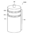
- FIG. 1 is a front view illustrating a configuration example of the imaging apparatus 100 according to the present embodiment.
- FIG. 2 is a rear view illustrating a configuration example of the imaging apparatus 100 according to the present embodiment.
- FIG. 3 is a rear view illustrating another configuration example of the imaging apparatus 100 according to the present embodiment.
- 4 to 6 are explanatory diagrams illustrating examples of the storage state of the display unit 102 of the imaging apparatus 100 according to the present embodiment. 4 to 6 show the relationship between the main body 101 and the display unit 102 when the imaging apparatus 100 is viewed from above, and the description of functional units unnecessary for the description is omitted for easy understanding.
- the imaging apparatus 100 includes an imaging unit that captures an image of a subject and acquires an image, and a display unit 102 that displays information such as an image and text.
- the imaging apparatus 100 includes an imaging unit and a display unit 102 in a cylindrical main body 101.
- the shape of the main-body part 101 is not limited to this shape, For example, other shapes, such as a rectangular parallelepiped, may be sufficient.
- a lens 103 constituting an imaging unit is provided on the front side of the main body 101, and a shutter button 104 is provided on the upper portion of the main body 101.
- an operation button 105 for operating the imaging apparatus 100 for example, as shown in FIG. 2, an operation button 105 for operating the imaging apparatus 100, a playback button 106a for reproducing a moving image, a power button 106b, for example, for zoom adjustment.
- a zoom adjustment dial 107a is provided.
- a focus adjustment dial 107 b for focus adjustment and a shutter speed adjustment dial 107 c for shutter speed adjustment may be provided on the back side of the imaging apparatus 100 (B), for example.
- the image acquired by the imaging unit is displayed on the display unit 102.
- the display unit 102 according to the present embodiment has flexibility.
- the display unit 102 is a film-like flexible display using, for example, a liquid crystal element or an organic EL element as a light emitting element, and can be flexibly deformed. For this reason, the display unit 102 can be stored by being rolled or folded.
- a displayable region Of the display surface of the display unit 102, an area of the display surface of the display unit 102 drawn from the main body unit 101 is referred to as a displayable region.
- the display unit 102 can be rolled and stored in the main body 101 while being smoothly curved on the winding shaft 102 a.
- the display unit 102 is provided with a plurality of folds along the winding shaft 102 a, the display unit 102 is wound around the winding shaft 102 ⁇ / b> A while being bent along the fold, and the main body unit 101 is You may store in.
- the display unit 102 is formed to be foldable as shown in FIG. 6, one end of the display unit 102 may be fixed to the outer surface of the main body unit 101 and may be expanded or folded with the fixed portion 102d as a fulcrum. Good. As described above, the display unit 102 may not be stored in the main body unit 101.
- the imaging apparatus 100 has a corresponding range corresponding to the displayable area of the display unit 102 extracted from the entire image range acquired by the imaging unit based on the drawing state of the display unit 102 with respect to the main body 101. Is displayed. For this reason, the imaging apparatus 100 includes a drawing state detection unit that detects a drawing state of the display unit 102.
- an infrared sensor may be used for the drawer state detection unit.
- the infrared sensor 108 is provided inside the main body 101 so as to face the display unit 102 wound around the winding shaft 102a.
- the infrared sensor 108 emits infrared light to the display unit 102 wound around the winding shaft 102 a and receives reflected infrared light reflected by the display unit 102.
- the extent to which the display unit 102 is pulled out from the main body unit 101 can be specified from the intensity of reflected light received by the infrared sensor 108 or the time from infrared emission to reception.
- an angle detection sensor capable of detecting a bending angle at each fold portion of the display unit 102 may be used as the drawer state detection unit.
- the extent to which the display unit 102 is pulled out from the main body unit 101 can be specified from the bending angle detected by each angle detection sensor.
- Such an imaging apparatus 100 includes, for example, an imaging mode in which an imaging target is imaged by an imaging unit, and a display mode in which the captured image is displayed on the display unit 102.
- the user can switch between the imaging mode and the display mode to acquire an image or display the acquired image on the display unit 102 for confirmation.
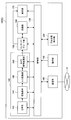
- FIG. 7 is a block diagram illustrating a functional configuration of the imaging apparatus 100 according to the present embodiment.
- the imaging apparatus 100 according to the present embodiment includes an operation unit 110, a drawer state detection unit 120, a control unit 130, an imaging unit 140, an encoding / decoding unit 150, and a recording unit 160. And a display unit 170.
- the operation unit 110 is a functional unit that allows a user to input an operation to the imaging apparatus 100.
- the operation unit 110 functions as a reception unit that receives user operation information in the imaging apparatus 100.
- the operation unit 110 is, for example, the shutter button 104, the operation button 105, the playback button 106a, the power button 106b, the zoom adjustment dial 107a, the focus adjustment dial 107b, the shutter speed adjustment dial 107c, and the like illustrated in FIGS.
- the operation input information input from the operation unit 110 is output to the control unit 130.
- the extraction state detection unit 120 detects the extraction state of the display unit 102 with respect to the main body unit 101.
- the drawer state detection unit 120 is, for example, the infrared sensor or the angle detection sensor shown in FIGS. 4 and 5. A detection result by the drawing state detection unit 120 is output to the control unit 130.
- the control unit 130 controls the overall functions of the imaging apparatus 100.
- the control unit 130 controls the imaging unit 140, the recording unit 160, and the display unit 160 based on operation input information from the operation unit 110. Further, the control unit 130 performs display processing of an image to be displayed on the display unit 102 based on the detection result of the drawing state detection unit 120. Further, the control unit 130 instructs the encoding / decoding unit 150 to execute encoding processing or decoding processing on the image data acquired by the imaging unit 140. In addition, the control unit 130 instructs the recording unit 160 to execute a recording process for recording image data on a storage medium. As described above, the control unit 130 controls each process of the imaging apparatus 100.
- the imaging unit 140 is a functional unit for acquiring an image.
- the imaging unit 140 includes an optical system 142, an imaging element 144, an A / D conversion unit 146, and a camera signal processing unit 148.
- the optical system 142 includes the lens 103 of FIG. 1, a diaphragm mechanism, and the like, and condenses incident light on the lens 103 onto the image sensor 144.
- the image sensor 144 is an optical sensor that converts an incident optical signal into an electrical signal.
- the image sensor 144 for example, a CCD image sensor, a CMOS image sensor, or the like is used.
- the image data converted into an electrical signal by the image sensor 144 is converted from an analog signal to a digital signal by the A / D converter 146.
- the image data converted into the digital signal is subjected to image processing by the camera signal processing unit 148 and converted into image data of a predetermined image format.
- the camera signal processing unit 148 is an integrated circuit for image processing, for example, and performs image processing such as interpolation calculation, color space conversion, gamma correction, aberration correction, noise reduction, and image compression.
- the imaging unit 140 is described as including the optical system 142, the imaging element 144, the A / D conversion unit 146, and the camera signal processing unit 148, but the present technology is not limited to such an example.
- the imaging unit 140 only needs to include at least the optical system 142 and the imaging element 144, and the A / D conversion unit 146 and the camera signal processing unit 148 may be provided in the imaging device 100 as functions outside the imaging unit 140. .
- the image data acquired by the imaging unit 140 is output to the encode / decode unit 150.
- the encoding / decoding unit 150 encodes the image data for recording on the storage medium by the recording unit 160. If the recording unit 160 has a reading function, the image data read from the storage medium is decoded and output to the display unit 170.
- the recording unit 160 records image data on a storage medium.
- the storage medium include a memory card incorporating a flash memory and a USB memory.
- the recording unit 160 may have a reading function of reading data from a recording medium.
- a CD-R, CD-RW, CD-RAM, DVD-R, DVD-RW, DVD-RAM, Blu-ray (registered trademark) is used instead of the recording unit 160 by a disk drive that can be connected to the imaging apparatus 100.
- Image data can also be recorded on an optical disc such as a disc.
- the display unit 170 is a display device that displays image data, and corresponds to the display unit 102 of FIGS.
- the display unit 170 displays an image captured by the imaging unit 140, an image stored in a storage medium, or the like after the control unit 130 performs display processing.
- the imaging apparatus 100 when the shutter button 104, which is one of the operation units 110, is pressed, the light incident from the lens 142 is converted into an electrical signal by the light receiving element 144 and output to the A / D conversion unit 146.
- the A / D converter 146 converts the electrical signal from an analog signal to a digital signal, and then the camera signal processor 148 performs image processing.
- the image data image-processed by the camera signal processing unit 148 is recorded on a storage medium by the recording unit 160 via the encoding / decoding unit 150 or displayed on the display unit 170. Regardless of the size that can be displayed on the display unit 102, the image data of the entire range of sizes acquired by the imaging unit 140 is recorded on the recording medium.
- the display unit 102 of the imaging apparatus 100 has flexibility, and when the display unit 102 is not used as shown in FIGS. It is folded into 101 and stored. In use, the display unit 102 accommodated in the main body unit 101 is pulled out and expanded. The display unit 102 may be used by pulling out only a part or may be used by pulling out the entire display unit 102. The pull-out amount of the display unit 102 is changed depending on the space where the image capturing apparatus 100 is used and what size the user wants to display on the display unit 102.
- the display area of the image changes depending on the drawing state of the display unit 102.
- the imaging apparatus 100 when the captured image acquired by the imaging unit 140 is displayed on the display unit 102, the entire range of the captured image is supported according to the drawing state of the display unit 102 with respect to the main body unit 101. Display a range image.
- the image display process on the display unit 102 according to the drawing state of the display unit 102 with respect to the main body unit 101 will be described with reference to FIG.
- the upper diagram in FIG. 8 shows a state in which the display unit 102 is partially opened and a part of the image is displayed
- the lower diagram in FIG. 8 shows a state in which the entire range of the image is displayed on the display unit 102.
- FIG. 8 when the display unit 102 is opened to the full display state, the entire range of the image captured by the imaging unit 140 is displayed on the display unit 102.
- the display unit 102 is partially opened with respect to the main body unit 101, as shown on the left side of the upper diagram in FIG.
- the upper diagram in FIG. 8 shows a state in which the display unit 102 is partially opened and a part of the image is displayed
- the lower diagram in FIG. 8 shows a state in which the entire range of the image is displayed on the display unit 102.
- the control unit 130 of the imaging apparatus 100 determines a range to be displayed on the display unit 102 from the entire range of the captured image in response to the user performing an operation of pulling out and opening the display unit 102 from the drawing state detection unit 120.
- the control unit 130 determines to display the range to be displayed on the display unit 102 in order from the side where the main body unit 101 is positioned with respect to the display unit 102. Accordingly, the captured image is displayed on the display unit 102 so as to correspond to the imaging target actually viewed by the user.
- the display unit 102 when it is determined that the range to be displayed on the display unit 102 from the entire range of the captured image is displayed in order from the drawing side end side of the display unit 102, the display unit 102 is pulled out. As the image is displayed, the captured image displayed on the display unit 102 also moves in the pull-out direction. As described above, since a part of the captured image displayed on the display unit 102 is also moved in accordance with the operation of pulling out or storing the display unit 102, the user moves the line of sight to the display unit 102. The operability will be reduced.
- the captured image can be presented to the user without a sense of incongruity on the flexible display unit 102 that can change the display area, and operability can be improved.
- display processing by the control unit 130 of the imaging apparatus 100 according to the present embodiment will be described in detail.
- FIG. 9 is a flowchart showing display processing by the control unit 130 according to the present embodiment.
- FIG. 10 is an explanatory diagram for explaining the range of a captured image displayed on the display unit 102 that changes in accordance with the pulling state of the display unit 102 with respect to the main body unit 101.
- FIG. 11 is a flowchart illustrating processing for determining a display range of a captured image.
- the image display processing according to the present embodiment is started when, for example, the power button 106b is pressed and the imaging apparatus 100 starts functioning in the imaging mode.
- the imaging apparatus 100 first detects the drawing state of the display unit 102 by the drawing state detection unit 120 (S100).
- the drawing state detection unit 120 S100
- the infrared sensor 108 or the angle detection sensor can be used for the drawer state detection unit 120.
- the withdrawal state detection unit 120 outputs the detection result to the control unit 130.
- the control unit 130 specifies how much the display unit 102 is pulled out from the main body unit 101 based on the detection result by the drawing state detection unit 120.
- the extraction state of the display unit 102 can be specified from the intensity of reflected light received by the sensor or the time from infrared emission to reception.
- the extraction state of the display unit 102 can be specified from the bending angle detected by each angle detection sensor.
- the pull-out state of the display unit 102 is represented by a length L in the pull-out direction of the display unit 102 pulled out from the main body unit 101 (hereinafter referred to as “the pull-out length”).
- the drawer length L can take a value from 0 (fully closed state of the display unit 102) to the length L max of the display unit 102 in the drawer direction.
- the control unit 130 calculates the range of the captured image to be displayed on the display unit 102 based on the extraction length L of the display unit 102 (S110).
- the entire range of the captured image acquired by the imaging unit 140 is determined according to the angle of view ⁇ of the lens 103 and the performance of the imaging element 144.
- the minimum value of the pull-out length L of the display unit 102 that can display the entire range of the captured image is set as the full-display pull-out length Ls.
- This state is referred to as a full display state. In the full display state, for example, as shown in FIG. 10, the entire range of the captured image 202 is displayed on the display unit 102.
- the extraction length L of the display unit 102 is smaller than the total display extraction length Ls, a corresponding range that is a part of the entire range of the captured image 202 is displayed.
- the control unit 130 first determines whether or not the extraction length L of the display unit 102 with respect to the main body unit 102 is smaller than the total display extraction length Ls (S112). When the extraction length L is smaller than the total display extraction length Ls, the control unit 130 determines a range from the reference end to the length L in the extraction direction in the captured image 202 as a range to be displayed on the display unit 102 (S114). ).
- the reference end is a boundary between the display unit 102 and a displayable area drawn from the main body 101 and the main body 101. In the example of FIG. 10, the left end of the displayable area of the display unit 102 is the reference end.
- the control unit 130 determines the range from the left side of the captured image 202 to the length L as the display range. On the other hand, when the extraction length L is equal to or longer than the total display extraction length Ls, the control unit 130 determines the entire range of the captured image 202 as a range to be displayed on the display unit 102 (S116). In this way, the range of the captured image 202 displayed on the display unit 102 is determined.
- the control unit 130 performs control so that the determined display range is displayed in the displayable area of the display unit 102 ( S120). At this time, the control unit 130 displays the display range of the captured image 202 from the reference end (left end in the example of FIG. 10) side of the display unit 102. Thereby, the image displayed on the display unit 102 does not move in the pull-out direction, and the captured image 202 displayed on the display unit 102 can be viewed with the same correspondence as the imaging target that the user is viewing.
- the imaging range included in the angle of view of the lens 103 is equally divided into a left range S1 and a right range S2.
- the full display state the entire range of the captured image 202 is displayed on the display unit 102.
- the partial display state the display unit 102 displays only the extraction length L from the imaging range S1 on the reference end side.
- the range S1 on the left side of the imaging range from the left side of the displayable area of the display unit 102 is displayed.
- the control unit 130 determines whether or not an instruction to end shooting is input from the user (S130). For example, it may be determined that there has been an instruction to end shooting, such as when the power is turned off or when the shooting mode is switched to the display mode.
- the control unit 130 ends the display process of FIG.
- the control unit 130 repeatedly executes the processing from step S100.
- the control unit 130 of the imaging apparatus 100 displays the display range of the captured image 202 according to whether or not the extraction length L of the display unit 102 is equal to or greater than the total display extraction length Ls. To decide.
- the length L max in the pull-out direction of the display unit 102 may be larger than the total display pull-out length Ls.
- the control unit 130 may display information other than the captured image 202, for example, in the excess portion.
- the display unit 102 is further pulled out from a state where it is pulled out to the full display state. That is, the drawer length L of the display unit 102 is larger than the total display drawer length Ls.
- This state is referred to as an expanded state.
- the control unit 130 controls the area A (that is, the main body side area from the reference end side of the display unit 102 to the entire display extraction length Ls.
- the captured image 202 is displayed in the entire range.
- a region B that is, a drawer-side region; hereinafter, also referred to as “extended region B”
- extended region B a region B from the total display extraction length Ls to the extraction length L in the displayable region of the display unit 102. Is displayed.
- the length of the extension region B in the pull-out direction is La.
- the length La is the difference between the drawer length L and the total display drawer length Ls.
- the captured image 204 may be displayed in the extended area B.
- the display unit 102 when the display unit 102 is in the expanded state, other information such as the captured image 204 is displayed on the display unit 102 together with the captured image 202, so that the user can capture the image while confirming the already captured image. be able to.
- the information displayed in the expanded area B of the display unit 102 is not limited to the captured image 204.
- shooting information 206 of the captured image 204 may be displayed in the extended area B together with the captured image 204.
- Examples of the shooting information 206 include shooting date / time, ISO, aperture setting, and the like.
- the display unit 102 is further pulled out from the state of FIG. 13 and the expansion area B is expanded, for example, the captured image 204 displayed in the expansion area B is enlarged and displayed as shown in the center diagram of FIG. May be.
- the display unit 102 when the display unit 102 is pulled out from the state of the central view of FIG. 13 and the expansion area B is expanded, for example, as shown in the lower left side of FIG. 13, a plurality of captured images 204, for example, two captured images 204a and 204b are displayed. It may be displayed in the extended area B. Alternatively, as shown on the right side in the lower diagram of FIG. 13, an operation input unit 300 that inputs a shooting control operation of the imaging unit 140 may be displayed together with the shot image 204. At this time, the display unit 102 is provided with a touch panel capable of detecting contact or proximity of an operation body such as a finger.
- the operation input unit 300 includes, for example, a circular dial operation unit 302, a horizontal dial operation unit 304, a vertical dial operation unit 306, an operation button 308, and the like.
- the operation input unit 300 only needs to include at least one operation unit, and a plurality of operation input units 300 may be provided as illustrated on the right side of the lower diagram of FIG.
- functions such as the shutter button 104, the playback button 106a, the zoom adjustment dial 107a, the focus adjustment dial 107b, and the shutter speed adjustment dial 107c provided in the main body 101 are assigned to the operation units of the operation input unit 300. Good.
- (B) Enlarged display of the captured image displayed in the extended area
- the display unit 102 is in the expanded state, and the captured image 202 and the captured image 204 are displayed on the display unit 102 as shown in the upper diagram of FIG. To do.
- the photographed image 204 may be enlarged and displayed as shown in the lower diagram of FIG.
- Selection of the photographed image 204 is performed by the operation unit 110 provided in the main body unit 101, for example.
- the display unit 102 is provided with a touch panel, the user can directly select the captured image 204 or perform an operation input using the operation input unit 300 provided in the extended area B.
- the enlarged captured image 204 may be displayed in the captured image area A beyond the expansion area B. Further, the captured image 202 may be reduced and displayed so that the captured image 202 can be visually recognized even when the captured image 204 is enlarged.
- the imaging apparatus 100 may be capable of shooting not only a still image but also a moving image.
- the control unit 130 displays the moving image 208 being shot in the captured image region A of the display unit 102 and is recorded in the extended region B during moving image shooting. Still images may be displayed.
- the shutter button 104 when a user presses the shutter button 104, for example, when a moving image is shot in the imaging mode, an image at the time when the shutter button 104 is pressed is acquired as a still image.
- the moving image shooting time 211 and the time axis 212 may be displayed.
- the still images 214a to 214c acquired during moving image shooting may be displayed in association with the position of the time axis 212 corresponding to the time when the still images 214a to 214c are acquired.
- the user can recognize when and what kind of still image is acquired during moving image shooting.
- a playback button 216 for playing back a moving image may be provided in the extended area B.
- the play button 216 When the play button 216 is touched, the moving image being recorded may be chased and reproduced if the moving image is being recorded, or the recorded moving image may be reproduced after the moving image is recorded.
- the selected one of the still images 214a to 214c displayed in the extended area B as shown in FIG. 15 may be enlarged and displayed as described with reference to FIG.
- the reproduced moving image or the enlarged still image may be displayed in the extended area B, or may be displayed in the whole or a part of the displayable area including the captured image area A.
- the imaging device 100 has a flexible display unit 102.
- the control unit 130 performs control so that the entire range of the captured image 202 is displayed on the display unit 102 when the display unit 102 is in the full display state.
- the control unit 130 controls the display unit 102 to display a range from the reference end to the extraction length L in the extraction direction in the captured image 202.
- the captured image 202 is displayed on the display unit 102 in a state in accordance with the user's intention, and the captured image can be presented to the user without a sense of incongruity on the display unit 102, thereby improving operability.
- FIG. 16 is explanatory drawing explaining the display process by the control part 130 which concerns on this embodiment.
- FIG. 17 is an explanatory diagram illustrating a method for determining the display range of the captured image 202 in accordance with the focal length of the user's eyes. Note that in this embodiment, the configuration and function of the imaging apparatus 100 are the same as those in the first embodiment, and thus description thereof is omitted here.
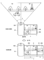
- the control unit 130 performs display processing for displaying the captured image 202 on the display unit 102 in accordance with the focal length of the user's eye. For example, as illustrated in FIG. 16, when the user is viewing the display unit 102 from the position E ⁇ b> 1, an imaging target ahead of the user's line of sight is displayed on the display unit 102. By displaying the captured image 202 on the display unit 102 in this way, the user can see the captured image 202 displayed on the display unit 102 as if seeing through the imaging target.
- control unit 130 determines the display range of the captured image 202 based on the focal length of the user's eyes and the drawing state of the display unit 102 with respect to the main body unit 101. It is assumed that the distance between the user's eye position E1 and the display unit 102 is substantially constant. At this time, the distance is set to a general human eye focal length (for example, about 50 mm).
- Control unit 130 first acquires an extraction length L of the display unit 102, calculates the center position O E of the displayable region in the drawing direction of the display unit 102.
- the center position O E is an intermediate position of the pull-out length L.
- the lens 103 exists at the position of the user's eye to the center position O E. That is, the lens 103 is present in a position spaced a distance Lb to the display unit 102 side from the position O L of the actual lens 103 of the imaging apparatus 100.
- Controller 130 when the lens 103 is assumed to be in the center position O E, the display range of the range of the captured image 202 clipped by the focal length of the eye of a user set.
- the range of the imaging target ahead of the line of sight of the user who views the display unit 102 is specified as the display range from the entire range 200 of the captured image 202 shown in FIG. 16 and 17, the length D represents the length in the pull-out direction in the entire range 200 of the captured image 202.
- the imaging device 100 is provided with a detection sensor (not shown) that detects the distance from the display unit 102 to the position of the user's eye
- the distance detected by the detection sensor is set to the user's eye. May be used as the focal length.
- the focal distance of the user's eyes can be made variable, the range of the captured image 202 displayed in the displayable area of the display unit 102 can be changed according to the focal distance.
- the captured image 202 displayed when the user's eyes are at the position E ⁇ b> 2 having a shorter focal length is displayed when the user's eyes are at the position E ⁇ b> 1.
- a wider range will be displayed. In this way, by changing the display range of the captured image 202 according to the position of the user's eyes, the user can view the captured image 202 as if seeing through the imaging target.
- the control unit 130 displays the captured image 202 on the display unit 102 in accordance with the focal length of the user's eye.
- the captured image 202 corresponding to the imaging target ahead of the line of sight of the user viewing the display unit 102 is displayed on the display unit 102 in accordance with the user's intention, and the captured image 202 is displayed on the display unit 102 as the user.
- FIGS. 18 to 22 are explanatory diagrams for explaining display processing by the control unit 130 according to the present embodiment.
- the imaging apparatus 100 according to the present embodiment is different from the first embodiment in that it includes two imaging units 140.
- Other configurations and functions of the imaging apparatus 100 are the same as those of the first embodiment, and thus description thereof is omitted here.
- the imaging apparatus 100 includes two lenses, a first lens 103a and a second lens 103b, as shown in FIG.
- Each lens 103 is provided as an optical system 142 of a different imaging unit 140.
- the first lens 103a and the second lens 103b may be any one of a wide-angle lens, a telephoto lens, and a zoom lens, for example.
- the first lens 103a and the second lens 103b acquire captured images 202a and 202b in ranges corresponding to the respective angles of view ⁇ a and ⁇ b.
- the control unit 130 displays the captured images 202 a and 202 b acquired by the imaging unit 140 corresponding to the lenses 103 a and 103 b in the displayable area of the display unit 102. For example, as illustrated in FIG. 18, the control unit 130 displays the first captured image 202a over the entire displayable area of the display unit 102, and the second captured image 202b is smaller than the first captured image 202a. The image may be displayed on 202a. Alternatively, as illustrated in FIG. 19, the control unit 130 may display the first captured image 202a and the second captured image 202b on the display unit 102 with substantially the same size.
- the control unit 130 displays the first captured image 202a by the first lens 103 over the entire displayable area of the display unit 102, and displays the first captured images 202b1 and 202b2 by the second lens 103b. You may display on the 1st captured image 202a so that it may overlap.
- a plurality of second captured images 202b1 and 202b2 illustrated in FIG. 20 are images captured at different capturing times by the image capturing unit 104 corresponding to the second lens 103b.
- the control unit 130 performs display control so that each of the second captured images 202b1 and 202b2 is displayed at a position corresponding to the first captured image 202a.
- the relevance of the captured images 202a, 202b1, 202b2 captured by the lenses 103a, 103b can be shown to the user.
- control unit 130 When performing such display processing, the control unit 130 will be described in the first embodiment or the second embodiment during display processing of at least one of the first captured image 202a and the second captured image 202b.
- the display process according to the pulled-out state of the display unit 102 is performed. Thereby, it is possible to present the captured images 202a and 202b subjected to the display process according to the drawing state of the display unit 102 to the user without feeling uncomfortable.
- the control unit 130 causes the image captured by the lenses 103 a and 103 b to be displayed in the displayable area of the display unit 102.
- a moving image is acquired by the imaging unit 140 corresponding to the first lens 103a and a still image is acquired by the imaging unit 140 corresponding to the second lens 103b.
- a moving image 208a is displayed in the displayable area of the display unit 102 as shown in FIG.
- the shooting time 211 and the time axis 212 of the moving image 208a may be displayed in the displayable area.
- still images 202b1 and 202b2 are acquired by the second lens 103b.
- the control unit 130 may display these still images 202b1 and 202b2 in association with the position of the time axis 212 corresponding to the time when the still images 202b1 and 202b2 are acquired.
- the user can recognize when and what kind of still image is acquired during moving image shooting.
- a playback button 216 for playing back the moving image 208a may be provided in the displayable area.
- the play button 216 When the play button 216 is touched, the moving image being recorded may be chased and reproduced if the moving image is being recorded, or the recorded moving image may be reproduced after the moving image is recorded.
- a selected one of the still images 202 b 1 and 202 b 2 displayed in the displayable area may be enlarged and displayed.
- the moving image 208a is reproduced and displayed in the displayable area, as shown in FIG. 22, the moving image 208a is displayed in the entire displayable area, and the still image is displayed at the timing when the reproduction time becomes the still image acquisition time. 202b may be displayed.
- the moving image 208 a is displayed in the displayable area of the display unit 102.
- the shooting time 211 and the time axis 212 of the moving image 208a may be displayed in the displayable area.
- a playback pointer 217 indicating the current playback time point or a still image acquisition pointer 218 indicating the time point when the still image 202b captured by the second lens 103b is recorded may be displayed on the time axis 212.
- the playback pointer 217 moves on the time axis 212 according to the playback time.
- a plurality of still image acquisition pointers 218 may be displayed according to the number of acquired still images 202b.
- the still image 202b is displayed in at least a part of the displayable area as shown in the lower diagram of FIG.
- the display position of the still image 202b is not particularly limited, the still image 202b may be displayed in a portion where a characteristic imaging target such as a person or a building of the moving image 208a being reproduced is not displayed.
- the displayed still image 202b is not displayed at a predetermined timing.
- the timing at which the still image 202b is not displayed may be, for example, after a predetermined time (for example, several seconds) has elapsed from the display time, or before the playback time of the moving image 208a reaches the time when the next still image 202 is acquired. .
- the display control by the control unit 130 of the imaging device 100 according to the third embodiment has been described above. Even when the two lenses 103a and 103b are provided as in the present embodiment, display processing corresponding to the pulled-out state of the display unit 102 is performed as in the above-described embodiment. As a result, the captured image 202 is displayed on the display unit 102 in a state in accordance with the user's intention, and the captured image 202 that has been subjected to the display process according to the drawing state of the display unit 102 is presented to the user without feeling uncomfortable. be able to.
- FIG. 23 is an explanatory diagram illustrating functions of the imaging apparatus 100 (E) according to the present embodiment.
- FIG. 24 is a block diagram illustrating a functional configuration of the imaging apparatus 100 (E) according to the present embodiment.
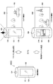
- FIG. 25 is an explanatory diagram illustrating switching between the camera function and the browser function based on the tilt of the imaging device 100 (E).
- the imaging device 100 (E) according to the present embodiment has a communication function in addition to a camera function for imaging an imaging target. That is, as illustrated in FIG. 24, the imaging apparatus 100 (E) further includes a communication unit 180 in the configuration illustrated in FIG.
- the communication unit 180 is a communication interface configured with a communication device or the like for connecting to the communication network 10.
- the communication unit 180 may be a wireless LAN (Local Area Network) compatible communication device, a wireless USB compatible communication device, or a wire communication device that performs wired communication.
- the imaging device 100 (E) functions as an Internet terminal having a call function, a web browser function, and the like.
- Such an imaging device 100 (E) may be formed as the imaging devices 100 (A) and (B) shown in FIGS.
- a touch panel 109 may be provided on the back side.
- the touch panel 109 has a display device such as a liquid crystal panel integrated with an input device such as a touch sensor, and an operation input can be performed by bringing an operating body into contact with or approaching the touch panel 109 while viewing information displayed on the touch panel 109.
- a display device such as a liquid crystal panel and an input device such as a touch sensor may be provided separately.
- the imaging device 100 (E) includes a camera function that functions in the imaging mode, a browser function that functions in the display mode, and a communication function.
- a switching button (not shown) for switching each function may be provided in the imaging apparatus 100 (E), and each function may be switched in order each time the switching button is pressed. .
- these functions may be switched based on the drawing state of the display unit 102 of the imaging apparatus 100 (E), the operation of the operation unit 110, or the like.
- the communication function is activated.
- the display unit 102 of the imaging apparatus 100 (E) is closed as shown in the left side of FIG. 23, the communication function is activated.
- the display unit 102 of the imaging device 100 (E) is pulled out from the main body unit 101, the camera function or the browser function is activated.
- the camera function may be made to function when the display unit 102 is pulled out from the main unit 101 and the shutter button 104 is pressed, for example. Specifically, for example, the camera function may be activated when the display unit 102 is pulled out while the shutter button 104 is pressed. Alternatively, the camera function may be activated when the shutter button 104 is pressed for a short time such as about 1 second before the display unit 102 is pulled out. At this time, the shutter button 104 may be pressed halfway or momentarily.
- the captured image 202 acquired by the imaging unit 140 is displayed on the pulled out display unit 102. At this time, the captured image 202 is displayed on the display unit by the display processing of each embodiment described above.
- the browser function may be caused to function when the display unit 102 is pulled out from the main body unit 101 when, for example, the reproduction candidate of the moving image 208 is displayed on the touch panel 109.
- the reproduction candidates for the moving image 208 are displayed on the touch panel 109 as thumbnails 210 of the moving image 208, for example. If there is one thumbnail 210 displayed on the touch panel 109, a moving image 208 corresponding to the thumbnail 210 is displayed on the display unit 102 and reproduced. When there are a plurality of thumbnails 210 displayed on the touch panel 109, one thumbnail 210 to be played back is selected and then the display unit 102 is played back so that a moving image 208 corresponding to the selected thumbnail 210 is displayed. It is displayed on the display unit 102 and reproduced.
- the display processing of each embodiment described above can also be applied to the reproduction display of the moving image 208 on the display unit 102.
- the function may be switched according to the attitude of the main body 101 of the imaging apparatus 100 (E).
- the imaging device 100 (E) includes, for example, a gyro sensor, an acceleration sensor, and the like.
- the camera function is activated, for example, since the shutter button 104 is provided on the upper surface of the imaging device 100 (E), the imaging device 100 (E) is often used upright as shown on the left side of FIG. .
- the browser function is activated, if the shape of the imaging apparatus 100 (E) as shown in FIG.
- the camera function and the browser function may be switched based on the angle ⁇ formed between the attitude axis C of the imaging device 100 (E) and the ground G.
- the orientation axis C of the imaging device 100 (E) is an axis parallel to the longitudinal direction of the imaging device 100 (E), and is perpendicular to the pulling direction of the display unit 102 in this example.
- the camera function is made to function because the shutter button 104 is on the vertically upper side.
- the browser function is activated.
- the angle ⁇ th can be set to 45 °, for example.
- FIG. 25 is an example of switching between the camera function and the browser function, and the relationship between the orientation of the imaging device 100 and the angle ⁇ th can be set as appropriate according to the shape of the imaging device 100 and the like. Further, the camera function and the browser function are switched based on the attitude of the imaging apparatus 100, but the user can also switch between these functions by operating the operation unit 110.
- the functional configuration of the imaging device 100 (E) according to the fourth embodiment has been described above. Even in the case where the communication function is provided in addition to the camera function and the browser function as in the present embodiment, when the camera function or the browser function is made to function, display processing corresponding to the drawer state of the display unit 102 is performed as in the above-described embodiment. Thus, the captured image 202 is displayed on the display unit 102 in a state in accordance with the user's intention, and the captured image that has been subjected to the display process according to the drawing state of the display unit 102 is presented so that the user does not feel uncomfortable. Can do. In addition, by performing in association with the operation and posture of the imaging apparatus 100 (E) when a function that uses switching of each function is functioning, it is possible to reduce the load of the user's function switching operation.
- a receiving unit that receives user operation information; Of the entire image range acquired by the imaging unit based on the drawing state of the flexible display unit that is received by the receiving unit and that can be pulled out with respect to the main unit of the imaging device.
- a control unit that determines a corresponding range corresponding to the displayable region of the display unit that has been pulled out;
- An information processing apparatus comprising: (2) The control unit determines the corresponding range from an end corresponding to the direction of the main body unit corresponding to the display unit of the entire image range based on the length of the drawing amount of the display unit.
- control unit is determined based on a focal length of a user's eye viewing the corresponding range.
- control unit determines a corresponding range for each image acquired by the imaging unit, and determines the corresponding range according to the arrangement of the imaging units.
- the information processing apparatus according to (1) which is disposed in the displayable area.
- the control unit displays the entire image range in the main body side region of the displayable region, and the display is possible.
- the information processing apparatus according to any one of (1) to (4), wherein a photographed image is displayed in an extraction-side region of the region.
- the control unit changes at least one of a display size and a display number of the photographed image displayed in the drawer-side region according to a drawing amount of the display unit, (5) The information processing apparatus described in 1. (7) When one or a plurality of the photographed images are selected from the photographed images displayed in the drawer side area, the control unit makes the drawer side area larger than the body side area. The information processing apparatus according to 5) or (6). (8) The information processing apparatus according to any one of (5) to (7), wherein the control unit displays the captured information together with the captured images in the drawer-side area. (9) When the drawing amount of the display unit exceeds the drawing direction length of the entire image range, the control unit displays the entire image range in the main body side region of the displayable region, and the display is possible.
- the information processing apparatus according to any one of (1) to (8), wherein an operation input unit that inputs a shooting control operation of the imaging unit is displayed in a drawer side region of the region. (10) Based on the pulling-out state of the flexible display unit provided so as to be capable of being pulled out with respect to the main body of the imaging device, the extracted image range is acquired from the entire image range acquired by the imaging unit.
- an imaging unit An imaging unit; A main body having a receiving unit for receiving user operation information; A flexible display unit that can be pulled out from the main body unit; A control unit for determining a corresponding range corresponding to a displayable region of the display unit extracted from the entire image range acquired by the imaging unit, based on a drawing state of the display unit with respect to the main body unit;
- An imaging apparatus comprising:
Landscapes
- Engineering & Computer Science (AREA)
- Signal Processing (AREA)
- Multimedia (AREA)
- Computer Hardware Design (AREA)
- Theoretical Computer Science (AREA)
- Physics & Mathematics (AREA)
- General Physics & Mathematics (AREA)
- Human Computer Interaction (AREA)
- General Engineering & Computer Science (AREA)
- Studio Devices (AREA)
- Controls And Circuits For Display Device (AREA)
Abstract
Priority Applications (4)
| Application Number | Priority Date | Filing Date | Title |
|---|---|---|---|
| JP2015512335A JP6384473B2 (ja) | 2013-04-19 | 2014-02-20 | 情報処理装置、情報処理方法および撮像装置 |
| CN201480020689.2A CN105122785B (zh) | 2013-04-19 | 2014-02-20 | 信息处理设备、信息处理方法和摄像设备 |
| US14/782,048 US10051188B2 (en) | 2013-04-19 | 2014-02-20 | Information processing device and image shooting device for display of information on flexible display |
| EP14785999.5A EP2988487B1 (fr) | 2013-04-19 | 2014-02-20 | Dispositif et procédé de traitement d'informations et dispositif d'imagerie |
Applications Claiming Priority (2)
| Application Number | Priority Date | Filing Date | Title |
|---|---|---|---|
| JP2013088457 | 2013-04-19 | ||
| JP2013-088457 | 2013-04-19 |
Publications (1)
| Publication Number | Publication Date |
|---|---|
| WO2014171179A1 true WO2014171179A1 (fr) | 2014-10-23 |
Family
ID=51731140
Family Applications (1)
| Application Number | Title | Priority Date | Filing Date |
|---|---|---|---|
| PCT/JP2014/054077 Ceased WO2014171179A1 (fr) | 2013-04-19 | 2014-02-20 | Dispositif et procédé de traitement d'informations et dispositif d'imagerie |
Country Status (5)
| Country | Link |
|---|---|
| US (1) | US10051188B2 (fr) |
| EP (1) | EP2988487B1 (fr) |
| JP (1) | JP6384473B2 (fr) |
| CN (1) | CN105122785B (fr) |
| WO (1) | WO2014171179A1 (fr) |
Cited By (2)
| Publication number | Priority date | Publication date | Assignee | Title |
|---|---|---|---|---|
| EP3311246A4 (fr) * | 2015-06-22 | 2019-01-02 | LG Electronics Inc. | Dispositif d'affichage souple et son procédé de fonctionnement |
| JP2022037530A (ja) * | 2020-08-25 | 2022-03-09 | コニカミノルタ株式会社 | 情報処理装置 |
Families Citing this family (12)
| Publication number | Priority date | Publication date | Assignee | Title |
|---|---|---|---|---|
| KR102304305B1 (ko) | 2015-01-21 | 2021-09-23 | 엘지전자 주식회사 | 이동단말기 및 그 제어방법 |
| CN104699391B (zh) * | 2015-04-07 | 2018-10-12 | 联想(北京)有限公司 | 电子设备及其相机的控制方法 |
| KR102482330B1 (ko) | 2016-04-26 | 2022-12-29 | 삼성디스플레이 주식회사 | 플렉서블 표시 장치 및 플렉서블 표시 장치의 영상 보상 방법 |
| CN106027862A (zh) * | 2016-05-23 | 2016-10-12 | 青岛海信移动通信技术股份有限公司 | 焦距调整方法、装置及终端 |
| EP4071595A4 (fr) * | 2019-12-03 | 2023-08-16 | LG Electronics Inc. | Dispositif électronique de fourniture de contenu et son procédé de commande |
| KR102912345B1 (ko) | 2020-11-25 | 2026-01-15 | 삼성전자주식회사 | 전자 장치 및 전자 장치에서 컨텐츠를 표시하는 방법 |
| KR20220078381A (ko) | 2020-12-03 | 2022-06-10 | 삼성전자주식회사 | 플렉서블 디스플레이를 갖는 전자 장치 및 그의 상태 변경에 따른 촬영 방법 |
| CN114173029B (zh) * | 2021-11-01 | 2023-09-22 | 维沃移动通信有限公司 | 拍摄方法、装置及电子设备 |
| EP4383043A4 (fr) * | 2021-11-05 | 2024-12-25 | Samsung Electronics Co., Ltd. | Procédé de fourniture d'image et dispositif électronique prenant en charge ce procédé |
| CN114220348B (zh) * | 2021-12-17 | 2023-08-08 | 湖北长江新型显示产业创新中心有限公司 | 显示装置 |
| WO2023153629A1 (fr) * | 2022-02-14 | 2023-08-17 | 삼성전자 주식회사 | Appareil électronique ayant une structure de prévention d'inclinaison |
| EP4496300A4 (fr) * | 2022-04-19 | 2025-06-18 | Samsung Electronics Co., Ltd | Dispositif électronique comprenant un dispositif d'affichage flexible, et procédé de fonctionnement associé |
Citations (6)
| Publication number | Priority date | Publication date | Assignee | Title |
|---|---|---|---|---|
| JP2003295291A (ja) * | 2002-03-29 | 2003-10-15 | Konica Corp | カメラ |
| JP2005278058A (ja) * | 2004-03-26 | 2005-10-06 | Fuji Photo Film Co Ltd | 携帯型電子機器 |
| JP2006060585A (ja) * | 2004-08-20 | 2006-03-02 | Fuji Photo Film Co Ltd | デジタルカメラ |
| JP2006229907A (ja) * | 2005-01-20 | 2006-08-31 | Fuji Photo Film Co Ltd | 撮像装置 |
| JP2009021660A (ja) | 2007-07-10 | 2009-01-29 | Fujifilm Corp | デジタルカメラ |
| JP2011114509A (ja) * | 2009-11-26 | 2011-06-09 | Nikon Corp | 表示装置および撮像装置 |
Family Cites Families (4)
| Publication number | Priority date | Publication date | Assignee | Title |
|---|---|---|---|---|
| KR101453906B1 (ko) * | 2008-08-27 | 2014-10-21 | 엘지전자 주식회사 | 휴대 단말기 및 그 동작 제어방법 |
| US8279174B2 (en) * | 2008-08-27 | 2012-10-02 | Lg Electronics Inc. | Display device and method of controlling the display device |
| KR101521219B1 (ko) * | 2008-11-10 | 2015-05-18 | 엘지전자 주식회사 | 플렉서블 디스플레이를 이용하는 휴대 단말기 및 그 제어방법 |
| US8970455B2 (en) * | 2012-06-28 | 2015-03-03 | Google Technology Holdings LLC | Systems and methods for processing content displayed on a flexible display |
-
2014
- 2014-02-20 CN CN201480020689.2A patent/CN105122785B/zh active Active
- 2014-02-20 JP JP2015512335A patent/JP6384473B2/ja active Active
- 2014-02-20 EP EP14785999.5A patent/EP2988487B1/fr active Active
- 2014-02-20 WO PCT/JP2014/054077 patent/WO2014171179A1/fr not_active Ceased
- 2014-02-20 US US14/782,048 patent/US10051188B2/en active Active
Patent Citations (6)
| Publication number | Priority date | Publication date | Assignee | Title |
|---|---|---|---|---|
| JP2003295291A (ja) * | 2002-03-29 | 2003-10-15 | Konica Corp | カメラ |
| JP2005278058A (ja) * | 2004-03-26 | 2005-10-06 | Fuji Photo Film Co Ltd | 携帯型電子機器 |
| JP2006060585A (ja) * | 2004-08-20 | 2006-03-02 | Fuji Photo Film Co Ltd | デジタルカメラ |
| JP2006229907A (ja) * | 2005-01-20 | 2006-08-31 | Fuji Photo Film Co Ltd | 撮像装置 |
| JP2009021660A (ja) | 2007-07-10 | 2009-01-29 | Fujifilm Corp | デジタルカメラ |
| JP2011114509A (ja) * | 2009-11-26 | 2011-06-09 | Nikon Corp | 表示装置および撮像装置 |
Non-Patent Citations (1)
| Title |
|---|
| See also references of EP2988487A4 |
Cited By (2)
| Publication number | Priority date | Publication date | Assignee | Title |
|---|---|---|---|---|
| EP3311246A4 (fr) * | 2015-06-22 | 2019-01-02 | LG Electronics Inc. | Dispositif d'affichage souple et son procédé de fonctionnement |
| JP2022037530A (ja) * | 2020-08-25 | 2022-03-09 | コニカミノルタ株式会社 | 情報処理装置 |
Also Published As
| Publication number | Publication date |
|---|---|
| JPWO2014171179A1 (ja) | 2017-02-16 |
| CN105122785B (zh) | 2019-03-29 |
| JP6384473B2 (ja) | 2018-09-05 |
| EP2988487A4 (fr) | 2016-11-16 |
| US10051188B2 (en) | 2018-08-14 |
| CN105122785A (zh) | 2015-12-02 |
| EP2988487B1 (fr) | 2019-10-30 |
| US20160057356A1 (en) | 2016-02-25 |
| EP2988487A1 (fr) | 2016-02-24 |
Similar Documents
| Publication | Publication Date | Title |
|---|---|---|
| JP6384473B2 (ja) | 情報処理装置、情報処理方法および撮像装置 | |
| KR101983543B1 (ko) | 표시 제어장치 및 그 제어방법 | |
| US11388331B2 (en) | Image capture apparatus and control method thereof | |
| US8890993B2 (en) | Imaging device and AF control method | |
| JP5623915B2 (ja) | 撮像装置 | |
| US8654203B2 (en) | Imaging device controlling operation of a zoom lens and a focus lens to create movie image data | |
| JP6370140B2 (ja) | ズーム制御装置、撮像装置、ズーム制御装置の制御方法、ズーム制御装置の制御プログラムおよび記憶媒体 | |
| JP5074204B2 (ja) | カメラシステム、カメラ本体、交換レンズユニット、および撮像方法 | |
| JP2013013050A (ja) | 撮像装置及びこの撮像装置を用いた表示方法 | |
| JP6548436B2 (ja) | 焦点検出装置およびその制御方法 | |
| JP5855454B2 (ja) | 撮像装置 | |
| US10979619B2 (en) | Image capturing apparatus capable of highly-accurate autofocus calibration and control method thereof, and storage medium | |
| JP6302215B2 (ja) | 撮像装置 | |
| JP5940394B2 (ja) | 撮像装置 | |
| JP2014078826A (ja) | 撮像装置、その制御方法、および制御プログラム、並びに記録媒体 | |
| JP2018033013A (ja) | 制御装置、撮像装置、制御方法、プログラム、および、記憶媒体 | |
| US20240397204A1 (en) | Imaging device, control method, and program | |
| JP6818814B2 (ja) | 焦点検出装置およびその制御方法 | |
| JP6210699B2 (ja) | 撮像装置およびその制御方法 | |
| JP2021125867A (ja) | 画像処理装置、撮像装置、画像処理装置の制御方法、およびプログラム | |
| JP2013242408A (ja) | 撮像装置およびその制御方法 | |
| JP6504693B2 (ja) | 撮像装置、操作支援方法及び操作支援プログラム | |
| JP6659230B2 (ja) | 撮像装置、合成撮影方法及び合成撮影プログラム | |
| JP2025151064A (ja) | 表示制御装置及びその制御方法 | |
| JP2011228982A (ja) | 撮像装置 |
Legal Events
| Date | Code | Title | Description |
|---|---|---|---|
| 121 | Ep: the epo has been informed by wipo that ep was designated in this application |
Ref document number: 14785999 Country of ref document: EP Kind code of ref document: A1 |
|
| ENP | Entry into the national phase |
Ref document number: 2015512335 Country of ref document: JP Kind code of ref document: A |
|
| WWE | Wipo information: entry into national phase |
Ref document number: 2014785999 Country of ref document: EP |
|
| WWE | Wipo information: entry into national phase |
Ref document number: 14782048 Country of ref document: US |
|
| NENP | Non-entry into the national phase |
Ref country code: DE |