WO2014171380A1 - Embout d'échappement - Google Patents
Embout d'échappement Download PDFInfo
- Publication number
- WO2014171380A1 WO2014171380A1 PCT/JP2014/060314 JP2014060314W WO2014171380A1 WO 2014171380 A1 WO2014171380 A1 WO 2014171380A1 JP 2014060314 W JP2014060314 W JP 2014060314W WO 2014171380 A1 WO2014171380 A1 WO 2014171380A1
- Authority
- WO
- WIPO (PCT)
- Prior art keywords
- exhaust pipe
- sound
- heat shield
- muffler cutter
- insulating material
- Prior art date
- Legal status (The legal status is an assumption and is not a legal conclusion. Google has not performed a legal analysis and makes no representation as to the accuracy of the status listed.)
- Ceased
Links
Images




Classifications
-
- F—MECHANICAL ENGINEERING; LIGHTING; HEATING; WEAPONS; BLASTING
- F01—MACHINES OR ENGINES IN GENERAL; ENGINE PLANTS IN GENERAL; STEAM ENGINES
- F01N—GAS-FLOW SILENCERS OR EXHAUST APPARATUS FOR MACHINES OR ENGINES IN GENERAL; GAS-FLOW SILENCERS OR EXHAUST APPARATUS FOR INTERNAL-COMBUSTION ENGINES
- F01N13/00—Exhaust or silencing apparatus characterised by constructional features
- F01N13/14—Exhaust or silencing apparatus characterised by constructional features having thermal insulation
-
- F—MECHANICAL ENGINEERING; LIGHTING; HEATING; WEAPONS; BLASTING
- F01—MACHINES OR ENGINES IN GENERAL; ENGINE PLANTS IN GENERAL; STEAM ENGINES
- F01N—GAS-FLOW SILENCERS OR EXHAUST APPARATUS FOR MACHINES OR ENGINES IN GENERAL; GAS-FLOW SILENCERS OR EXHAUST APPARATUS FOR INTERNAL-COMBUSTION ENGINES
- F01N1/00—Silencing apparatus characterised by method of silencing
- F01N1/24—Silencing apparatus characterised by method of silencing by using sound-absorbing materials
-
- F—MECHANICAL ENGINEERING; LIGHTING; HEATING; WEAPONS; BLASTING
- F01—MACHINES OR ENGINES IN GENERAL; ENGINE PLANTS IN GENERAL; STEAM ENGINES
- F01N—GAS-FLOW SILENCERS OR EXHAUST APPARATUS FOR MACHINES OR ENGINES IN GENERAL; GAS-FLOW SILENCERS OR EXHAUST APPARATUS FOR INTERNAL-COMBUSTION ENGINES
- F01N1/00—Silencing apparatus characterised by method of silencing
- F01N1/003—Silencing apparatus characterised by method of silencing by using dead chambers communicating with exhaust gas flow passages
- F01N1/006—Silencing apparatus characterised by method of silencing by using dead chambers communicating with exhaust gas flow passages comprising at least one perforated tube extending from inlet to outlet of the silencer
-
- F—MECHANICAL ENGINEERING; LIGHTING; HEATING; WEAPONS; BLASTING
- F01—MACHINES OR ENGINES IN GENERAL; ENGINE PLANTS IN GENERAL; STEAM ENGINES
- F01N—GAS-FLOW SILENCERS OR EXHAUST APPARATUS FOR MACHINES OR ENGINES IN GENERAL; GAS-FLOW SILENCERS OR EXHAUST APPARATUS FOR INTERNAL-COMBUSTION ENGINES
- F01N1/00—Silencing apparatus characterised by method of silencing
- F01N1/02—Silencing apparatus characterised by method of silencing by using resonance
- F01N1/04—Silencing apparatus characterised by method of silencing by using resonance having sound-absorbing materials in resonance chambers
-
- F—MECHANICAL ENGINEERING; LIGHTING; HEATING; WEAPONS; BLASTING
- F01—MACHINES OR ENGINES IN GENERAL; ENGINE PLANTS IN GENERAL; STEAM ENGINES
- F01N—GAS-FLOW SILENCERS OR EXHAUST APPARATUS FOR MACHINES OR ENGINES IN GENERAL; GAS-FLOW SILENCERS OR EXHAUST APPARATUS FOR INTERNAL-COMBUSTION ENGINES
- F01N13/00—Exhaust or silencing apparatus characterised by constructional features
- F01N13/08—Other arrangements or adaptations of exhaust conduits
- F01N13/082—Other arrangements or adaptations of exhaust conduits of tailpipe, e.g. with means for mixing air with exhaust for exhaust cooling, dilution or evacuation
-
- F—MECHANICAL ENGINEERING; LIGHTING; HEATING; WEAPONS; BLASTING
- F01—MACHINES OR ENGINES IN GENERAL; ENGINE PLANTS IN GENERAL; STEAM ENGINES
- F01N—GAS-FLOW SILENCERS OR EXHAUST APPARATUS FOR MACHINES OR ENGINES IN GENERAL; GAS-FLOW SILENCERS OR EXHAUST APPARATUS FOR INTERNAL-COMBUSTION ENGINES
- F01N13/00—Exhaust or silencing apparatus characterised by constructional features
- F01N13/20—Exhaust or silencing apparatus characterised by constructional features having flared outlets, e.g. of fish-tail shape
-
- F—MECHANICAL ENGINEERING; LIGHTING; HEATING; WEAPONS; BLASTING
- F01—MACHINES OR ENGINES IN GENERAL; ENGINE PLANTS IN GENERAL; STEAM ENGINES
- F01N—GAS-FLOW SILENCERS OR EXHAUST APPARATUS FOR MACHINES OR ENGINES IN GENERAL; GAS-FLOW SILENCERS OR EXHAUST APPARATUS FOR INTERNAL-COMBUSTION ENGINES
- F01N2470/00—Structure or shape of exhaust gas passages, pipes or tubes
- F01N2470/02—Tubes being perforated
Definitions
- the present invention relates to a muffler cutter.
- Combustion gas (exhaust gas) discharged from the car engine is finally connected to the engine through exhaust manifold, exhaust manifold direct catalytic converter, front tube, underfloor catalytic converter, center muffler, main muffler, etc. It is discharged to the outside from the end (tail end) of the tail pipe (see, for example, Patent Document 1 (Japanese Patent Laid-Open No. 2008-190371)).
- a muffler cutter is generally attached to the end of the tail pipe, and the aesthetics and luxury of the vehicle are improved by this muffler cutter.
- the exhaust noise is likely to increase, and the load on the main muffler etc. is likely to increase. Therefore, the exhaust noise that cannot be absorbed by the main muffler, etc. is reduced, and the noise caused by the exhaust noise is reduced. Obtaining muffler cutters are becoming desirable.
- an object of the present invention is to provide a muffler cutter that is excellent in heat insulating properties and sound deadening properties and can improve the sound quality of exhaust sound.
- the present inventors conducted further diligent studies, a muffler cutter attached to a tail pipe of a vehicle exhaust system, and an exhaust pipe provided with a plurality of through holes on a side wall; A cylindrical heat shield provided coaxially with the exhaust pipe on the outside of the exhaust pipe, and a sound-absorbing heat insulating material filled between the exhaust pipe and the cylindrical heat shield.
- the sound-absorbing heat insulating material is curvedly filled only in a portion between the exhaust pipe and the cylindrical heat shield plate, and the exhaust pipe and the cylindrical heat shield plate A curved closed space is formed in the other part of the space, and the muffler cutter in which the distance between the exhaust pipe forming the closed space and the cylindrical heat shield plate is 1 to 50 mm.
- the present invention (1) A muffler cutter attached to a tail pipe of a vehicle exhaust system, An exhaust pipe having a plurality of through holes in the side wall; a cylindrical heat shield plate provided coaxially with the exhaust pipe on the outside of the exhaust pipe; and the exhaust pipe and the cylindrical shield. A sound-absorbing heat insulating material filled between the heat plate and The sound-absorbing heat insulating material is filled in a curved shape only in a part between the exhaust pipe and the cylindrical heat shield plate, and other than between the exhaust pipe and the cylindrical heat shield plate.
- a curved closed space is formed in this part, A muffler cutter, wherein a distance between the exhaust pipe forming the closed space and the cylindrical heat shield is 1 to 50 mm; (2) The muffler cutter according to (1), wherein the through-hole is provided in at least a portion of the side surface of the exhaust pipe facing the sound-absorbing heat insulating material. (3) The muffler cutter according to the above (1), wherein the sound-absorbing heat insulating material is filled in a curved shape between the exhaust pipe located on the vehicle main body side and a cylindrical heat shield when disposed.
- a part between the exhaust pipe and the cylindrical heat shield is a curved closed space, and the distance between the exhaust pipe and the cylindrical heat shield forming the closed space is set.
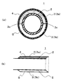
- FIG.1 (a) is a vertical sectional view of a perpendicular direction with respect to the muffler cutter 1 longitudinal direction
- FIG.1 (b) is the longitudinal direction of a muffler cutter
- FIG. 1 (b) is the longitudinal direction of a muffler cutter
- FIG. 1 (b) is the longitudinal direction of a muffler cutter
- FIG. 1 (b) is the longitudinal direction of a muffler cutter
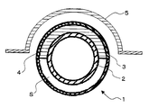
- FIG. It is sectional drawing explaining the usage pattern of the muffler cutter which concerns on this invention.
- It is a figure explaining the manufacture example of the muffler cutter which concerns on this invention.
- it is a schematic diagram of a high-temperature reflectance / transmittance measuring device used for measuring emissivity.
- FIG. 10A is an explanatory diagram of a muffler cutter obtained in a reference example of the present invention.
- FIG. 10A is a front view (left view) of the exhaust pipe 2 and a vertical sectional view taken along the line dd ′ of the front view (right view).
- FIG. 10 (b) shows a front view (left view) of the tubular heat shield 3 and a vertical sectional view (right view) taken along the line ee ′ of the front view.
- Fig. 10 (c) is a front view of the muffler cutter in which the tubular heat shield plate 3 shown in Fig. 10 (b) is coaxially fixed to the exhaust pipe 2 shown in Fig. 10 (a) (left figure).
- FIG. 10 (d) shows a vertical sectional view along the longitudinal direction of the muffler cutter shown in FIG. 10 (c). It is.
- FIG. 12 shows the exhaust pipe 2 in which a circular through hole is provided in the entire side wall on the downstream side (exhaust gas outflow side). It is a figure which shows the change of the sound pressure level of the tail pipe obtained by the reference example and comparative example of this invention.
- the muffler cutter of the present invention is a muffler cutter attached to a tail pipe of an exhaust system for a vehicle, the exhaust pipe having a plurality of through holes in a side wall, and the exhaust pipe outside the exhaust pipe. And a cylindrical heat insulating plate provided coaxially, and a sound absorbing heat insulating material filled between the exhaust pipe and the cylindrical heat insulating plate, the sound absorbing heat insulating material, Only a part between the exhaust pipe and the cylindrical heat shield is filled in a curved shape, and the other part between the exhaust pipe and the cylindrical heat shield is a curved closure. A space is formed, and the distance between the exhaust pipe forming the closed space and the cylindrical heat shield is 1 to 50 mm.
- FIG. 1 is a cross-sectional view showing an embodiment of a muffler cutter 1 according to the present invention
- FIG. 1 (a) is a vertical cross-sectional view perpendicular to the longitudinal direction of the muffler cutter 1
- FIG. ) Is a vertical cross-sectional view along the longitudinal direction of the muffler cutter 1.
- a muffler cutter 1 has an exhaust pipe 2.
- the exhaust pipe means a tubular material through which exhaust gas (combustion gas) flows, and the exhaust pipe is made of a material corresponding to the temperature of the exhaust gas flowing through the inside, It is preferable to select appropriately from those that can exhibit the desired temperature characteristics and sound absorption characteristics.
- the exhaust pipe those having heat resistance are suitable, and specific examples include a metal pipe and a resin pipe made of a heat-resistant resin, and a metal pipe is preferable.
- a stainless steel tube As the metal tube, a stainless steel tube (SUS tube) is mainly used from the viewpoint of heat resistance and corrosion resistance, but an aluminum tube (aluminum tube) may be used.
- the average thickness of the exhaust pipe is suitably 0.5 to 2.0 mm, more preferably 0.6 to 1.8 mm, and 0.6 to 1.5 mm. It is more appropriate.
- exhaustion means the arithmetic mean value when the thickness of three places is measured with a caliper.
- the outer diameter of the exhaust pipe is suitably 20 to 250 mm, more suitably 20 to 200 mm, even more suitably 25 to 150 mm, and 30 to 100 mm. It is more appropriate.
- the outer diameter of exhaust piping shall mean the value which measured the vertical cross section of exhaust piping with calipers.
- the outer diameter of the exhaust pipe is the maximum length when the vertical cross section of the exhaust pipe is measured with calipers. Shall mean.
- the temperature inside and outside the exhaust pipe can be easily controlled within a suitable range.
- the cross-sectional shape of the exhaust pipe is not particularly limited, and may be circular as shown in the cross-sectional view of FIG.
- the exhaust pipe is provided with a plurality of through holes in the side wall.
- Examples of the shape of the through hole include a circular shape, a square shape, and a slit shape.
- the exhaust pipe provided with the through hole may be formed by appropriately perforating a metal pipe, or may be a commercial product such as a punching metal.
- the exhaust pipe Since the exhaust pipe is provided with a plurality of holes in the side wall in the longitudinal direction, the exhaust pipe has entered a closed space provided between the exhaust pipe and a cylindrical heat shield plate described later. As a result of interference occurring while the exhaust sound reciprocates in the enclosed space, the sound pressure of high-frequency sound is reduced while improving the sound pressure of low-frequency sound (volume of low-frequency sound). It is thought to improve).
- the exhaust pipe is provided with through holes in 1 to 95% when the total outer surface area of the side wall portion where the through holes are to be provided is 100%. More preferably, 20 to 70% are provided with through holes, and more preferably 25 to 50% are provided with through holes.
- the exhaust pipe cannot exhibit sufficient strength, and the exhaust pipe
- the area of the through hole provided in the exhaust pipe is less than 1% of the total outer surface area of the exhaust pipe side wall where the through hole is to be provided, it is difficult to exhibit the effect of improving the volume of low frequency sound and the effect of improving the sound absorption of high frequency sound.
- the “total outer surface area of the side wall portion where the through-hole is to be provided” of the exhaust pipe refers to when the through-hole provided in the outermost peripheral portion is connected among the through-holes provided in the side wall of the exhaust pipe. Means the area of the inner part specified in.
- the through hole provided in the exhaust pipe is preferably provided in the side wall on the downstream side (exhaust gas exhaust side) of the exhaust pipe, and the longitudinal center of the exhaust pipe More preferably, it is provided on the side wall on the downstream side (the side from which the combustion gas is discharged).
- the through hole is provided on the side wall on the upstream side of the exhaust pipe (exhaust gas inflow side)
- the closed hole is provided in a closed space provided between the exhaust pipe and a cylindrical heat shield plate described later.
- the muffler cutter of this invention WHEREIN: It is preferable that the said through-hole is provided in the part facing the sound-absorbing heat insulating material mentioned later at least among the side surfaces of exhaust piping.
- the through hole provided in the side surface of the exhaust pipe is preferably provided so that 50 to 100% of the through hole faces a sound-absorbing heat insulating material described later, and 80 to 100% thereof. Is more preferably provided so as to face a sound-absorbing heat insulating material to be described later, more preferably 90 to 100% is provided so as to face a sound-absorbing heat insulating material described later, 100%) is more preferably provided so as to face a sound-absorbing heat insulating material to be described later.
- the through-hole provided in the side surface of the exhaust pipe is located on the vehicle body side when disposed, for example, when the entire outer surface of the exhaust pipe is divided into two semi-cylindrical parts. More preferably, the semi-cylindrical portion is formed.
- the sound absorption improvement effect of the high frequency sound by the sound absorption heat insulating material can be effectively exhibited, and the higher the ratio of the through holes provided in the part facing the sound absorption heat insulating material, the sound absorption The effect of improving the sound absorption of high frequency sound by the heat insulating material can be more effectively exhibited.
- a muffler cutter 1 As shown in FIG. 1, a muffler cutter 1 according to the present invention has a cylindrical heat shield plate 3 provided coaxially with the exhaust pipe 2 on the outer periphery of the exhaust pipe 2.
- the muffler cutter of the present invention employs a coaxial double circular tubular structure having an exhaust pipe and a cylindrical heat shield plate provided coaxially with the exhaust pipe on the outside of the exhaust pipe. Because the sound diffused to the outside from the side wall of the inner pipe (exhaust pipe) can be reflected and collected by the outer pipe (cylindrical heat shield), a wide range from the low frequency sound range to the high frequency sound range Further, as described above, the exhaust pipe is provided with a plurality of holes on the side wall in the longitudinal direction, thereby causing interference of sound waves, particularly low frequency sound. It is considered that the sound pressure of high-frequency sound can be reduced (the sound-absorbing property of high-frequency sound can be improved) while improving the sound pressure (volume of low-frequency sound).
- the heat shield means that which can suppress the heat radiated from the exhaust gas flowing through the exhaust pipe to the vehicle body side, and is radiated to the vehicle body side. It is preferable to appropriately select from materials made of a material that has heat resistance corresponding to the heat generated and does not deteriorate.
- the cylindrical heat shielding plate those having heat resistance and aesthetics are suitable, and specifically, a metallic one can be mentioned.
- stainless steel As the metal constituting the cylindrical heat shield, stainless steel (SUS) is mainly used from the viewpoints of heat resistance, corrosion resistance, aesthetics and the like, and aluminum may be used. Stainless steel is preferred because of its high properties.
- the cylindrical heat shield plate preferably has an emissivity of 0.1 to 50% at a wavelength of 2 to 15 ⁇ m, more preferably 0.1 to 40%. More preferably, it is 1 to 30%.
- the emissivity of the cylindrical heat shield when the emissivity of the cylindrical heat shield is within the above range, the heat release from the exhaust gas to the vehicle main body side is more effectively suppressed, and the heat deterioration of the vehicle main body is suppressed. It can be easily suppressed.
- emissivity (%) means a value calculated by the following formula.
- Emissivity (%) 100-reflectance (%)-transmittance (%)
- the reflectance (%) and transmittance (%) are electromagnetic waves having a wavelength of 2 to 15 ⁇ m with respect to a measurement sample (heat shield plate) under a temperature condition of 25 ° C. using a high-temperature reflectance / transmittance measuring device.
- Reflectance (%) (reflected light intensity / incident light intensity) ⁇
- Transmittance (%) (transmitted light intensity / incident light intensity) ⁇ 100
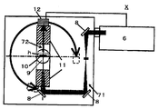
- a high-temperature reflectance / transmittance measuring apparatus As a high-temperature reflectance / transmittance measuring apparatus, the one shown schematically in FIG. In the high-temperature reflectivity / transmittance measuring apparatus X shown in FIG. 4, incident light 71 having a wavelength of 2 to 15 ⁇ m irradiated from a Fourier transform infrared spectrophotometer (FT-IR6100 type manufactured by JASCO Corporation) 6 is reflected. Reflected by the mirror 8 and guided into the sample chamber, the sample 10 attached to the center of the turntable 9 is irradiated. The sample 10 is heated by a halogen heater (UL-SH-V500 manufactured by Ushio Electric Co., Ltd.) 11 while being attached to a holder h provided at the center of the turntable 9. The intensity of the reflected light or transmitted light 72 from the sample 10 is detected by a detector 12 that is separately provided on the arm of the turntable 9 having the mounting portion as a rotation axis and circulates around the sample 10.
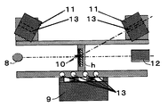
- FIG. 5 A structural example of the heating part of the high-temperature reflectance / transmittance measuring apparatus X is shown in a sectional view in FIG.
- halogen heaters 11 are installed on the front and back portions of the sample 10, and when the detector 12 captures reflected light or transmitted light from the sample 10, the halogen heater 11 blocks the optical path. It is installed at an angle on the top of the sample 10 so that there is no. When the reflected light or transmitted light is measured, the halogen heater 11 is also rotated together with the sample 10 so that the surface temperature of the sample 10 can always be kept constant. Cooling water 13 is introduced from the outside to the bottom of the turntable 9 on which the sample 10 is installed and the halogen heater 11 to circulate and cool.
- the average thickness of the cylindrical heat shield is suitably 0.5 to 2.0 mm, more suitably 0.6 to 1.8 mm, and 0.6 to 1.5 mm. It is even more appropriate to be.
- the average thickness of a cylindrical heat-shielding board means the arithmetic mean value when measuring the thickness of three places with a caliper.
- the outer diameter of the cylindrical heat shield is suitably 70 to 300 mm, more suitably 120 to 300 mm, even more suitably 125 to 250 mm, 130 to It is more suitable that it is 200 mm.
- the outer diameter of a cylindrical heat shield plate shall mean the value which measured the vertical cross section of the cylindrical heat shield plate with the caliper.
- the outer diameter of the cylindrical heat shield is measured with a caliper. It shall mean the maximum length when the vertical cross section of the cylindrical heat shield is a shape other than a circle. It shall mean the maximum length when
- the temperature inside and outside the heat shield can be easily controlled within a suitable range.
- the cross-sectional shape of the heat shield plate is not particularly limited, and may be substantially circular as shown in FIG.
- the cylindrical heat shield plate 3 includes an upper heat shield plate 3a in which the cylindrical object is halved, and a lower portion in which the cylindrical object is also halved. It is preferable to consist of the heat shield plate 3b. Since the heat shield plate 3 is composed of a half-shaped upper heat shield plate 3a and a half-shaped lower heat shield plate 3b, the muffler cutter of the present invention can be easily manufactured as described later. it can.
- the muffler cutter 1 of the present invention is sound-absorbing only at a part between an exhaust pipe 2 and a cylindrical heat shield 3 provided coaxially with the exhaust pipe 2.
- the heat insulating material 4 is filled in a curved shape (substantially C-shaped), and the other portion between the exhaust pipe 2 and the tubular heat shield plate 3 is curved (substantially C-shaped). ) A closed space S is formed.
- the sound-absorbing heat insulating material means a heat insulating material capable of reducing a sound pressure level at 800 to 20000 Hz at a 1/3 octave band frequency that is annoying for humans among vehicle exhaust sounds.
- glass wool mat glass mat
- silica fiber mat basalt fiber mat
- alumina siliceous fiber mat mullite fiber mat
- alumina fiber mat and other fibrous heat insulation Materials
- the thermal conductivity of the sound-absorbing heat insulating material is preferably 0.01 to 0.1 W / (m ⁇ K) under a temperature condition of 400 ° C., and is preferably 0.001 to 0.00. It is more preferably 08 W / (m ⁇ K), and further preferably 0.001 to 0.06 W / (m ⁇ K).
- the thermal conductivity of the sound-absorbing heat insulating material at room temperature (25 ° C.) is preferably 0.01 to 0.1 W / (m ⁇ K), and 0.001 to 0.08 W. / (M ⁇ K) is more preferable, and 0.001 to 0.06 W / (m ⁇ K) is further more preferable.
- the thermal conductivity means a value measured by a heat flow meter method.
- the sound-absorbing heat insulating material 4 is curved between the exhaust pipe 2 located on the vehicle body 5 side and the tubular heat shield plate 3 when installed. Is preferably filled.
- the heat-absorbing heat insulating material 4 is disposed on the vehicle main body 5 side, whereby thermal deterioration of the vehicle main body 5 due to exhaust heat of the exhaust gas can be more effectively suppressed.
- the thickness of the sound-absorbing heat insulating material is preferably 1 to 50 mm, more preferably 1 to 30 mm, still more preferably 4 to 20 mm, and 4 to 12 mm. More preferably.
- the thickness of a sound-absorbing heat insulating material means an arithmetic average value when thickness is measured at five points using a Peacock dial thickness gauge.
- the sound absorbing property of high frequency sound can be easily improved when filled between the exhaust pipe and the heat shield plate. At the same time, it is possible to more effectively improve the heat insulation by the heat insulating material or the cylindrical heat shield.
- the upper limit of the thickness is filled with the sound absorbing heat insulating material. It is defined by the distance between the exhaust pipe and the cylindrical heat shield.
- the bulk density of the sound-absorbing heat insulating material is preferably 50 to 400 kg / m 3 , more preferably 80 to 350 kg / m 3 , and 100 to 300 kg / m 3. Is more preferable.
- the thickness and bulk density of the sound-absorbing heat insulating material are within the above ranges, so that it is easy to improve the sound-absorbing property of high-frequency sound, and thermal deterioration of the member on the vehicle body side facing the muffler cutter Is easily suppressed, and the temperature inside the exhaust pipe is easily controlled within a certain range.
- the sound-absorbing heat insulating material is filled in a curved shape between the exhaust pipe and the tubular heat shield, but the sound-absorbing heat insulating material is 20% of the total outer surface area of the exhaust pipe. It is preferably set at ⁇ 80%, more preferably set at 30-70%, and further preferably set at 40-60%.
- the installation position of the sound-absorbing heat insulating material and the installation area with respect to the entire outer surface of the exhaust pipe are the shape of the opposing vehicle body side member, the sound-absorbing or heat insulating material to be imparted to the sound-absorbing heat insulating material. What is necessary is just to determine suitably according to sex etc.
- the sound-absorbing heat insulating material for example, when the entire outer surface of the exhaust pipe is divided into two semi-cylindrical parts, It is preferably formed on the entire outer surface. Specifically, as shown by a cross-sectional shape in FIG. 2, when the entire outer surface of the exhaust pipe 2 is divided into two semi-cylindrical parts, the sound-absorbing heat insulating material 4 is located on the vehicle body 5 side. It is preferably formed on substantially the entire outer surface of the cylindrical portion.
- the sound absorbing heat insulating material 4 together with the heat shield plate 3 as described above, when the muffler cutter is attached to the tail pipe of the exhaust system for a vehicle, the exhaust sound that cannot be absorbed by the main muffler or the like is reduced. Heat radiation to the vehicle body 5 side can be effectively suppressed, and thermal deterioration of the components on the vehicle body 5 side can be suitably suppressed.
- a curved closed space S is formed in a part between the exhaust pipe 2 and the cylindrical heat shield plate 3.
- the closed space S is formed in a curved shape between the exhaust pipe 2 and the tubular heat shield plate 3.
- the contact area with the exhaust pipe 2 on the outer surface of the exhaust pipe 2 is 80 to 20% of the total outer surface area of the exhaust pipe 2 (the installation area of the sound absorbing heat insulating material 4 is the total outer surface area of the exhaust pipe 2) Preferably 20 to 80%), preferably 70 to 30% (the installation area of the sound-absorbing heat insulating material 4 is 30 to 70% of the total outer surface area of the exhaust pipe). Is more preferable, and it is more preferable that the sound-absorbing heat insulating material 4 is provided so that the installation area of the sound-absorbing heat insulating material 4 is 40 to 60% of the total outer surface area of the exhaust pipe.
- the closed space means a space defined by the exhaust pipe, the tubular heat insulating material, and the sound absorbing heat insulating material.
- the closed space S is normally hollow (hollow) by the exhaust pipe 2, the tubular heat insulating material 3, and the sound-absorbing heat insulating material 4.
- both ends in the longitudinal direction of the closed space S are usually partitioned from the outside by wall portions.
- the boundary surface formed between the sound-absorbing heat insulating material 4 and the closed space S is not provided with a normal wall portion (partition), and the exhaust gases can move relative to each other.
- the muffler cutter of the present invention employs a substantially coaxial double circular tubular structure having an exhaust pipe and a cylindrical heat shield plate provided coaxially with the exhaust pipe on the outside of the exhaust pipe. Therefore, the sound diffused to the outside from the side wall of the inner pipe (exhaust pipe) can be reflected and collected by the outer pipe (cylindrical heat shield), so that a wide range from the low frequency sound range to the high frequency sound range can be obtained.
- the sound pressure can be increased in a range, and as described above, the exhaust pipe is provided with a plurality of holes in the side wall in the longitudinal direction. It is considered that the sound pressure of the high frequency sound can be lowered (the sound absorption of the high frequency sound can be improved) while improving the sound pressure of the wave sound (volume of the low frequency sound).
- the atmosphere in the enclosed space is preferably an air atmosphere, an inert atmosphere such as nitrogen, or a vacuum, and more preferably an air atmosphere.
- the closed space S may be appropriately filled with a backup material such as glass wool, steel wool, and aluminum wool as long as the effects of the present invention are not impaired.
- the closed space is hollow, and is formed in a curved shape between the exhaust pipe located on the opposite side to the vehicle main body side and the cylindrical heat shield plate when installed. It is preferable that it is made.
- the closed space is formed on the entire outer surface of the semi-cylindrical portion that is located on the side opposite to the vehicle body side when the exhaust pipe is divided into two semi-cylindrical portions. It is preferable that it is formed. Specifically, as shown in a cross-sectional shape in FIG. 2, when the entire outer surface of the exhaust pipe 2 is divided into two semi-cylindrical parts, the closed space S is positioned on the side opposite to the vehicle body 5 side.
- the volume of the low frequency sound can be easily improved when the muffler cutter is attached to the tail pipe of the exhaust system for a vehicle, and the side opposite to the vehicle main body side can be improved. Heat dissipation from the exhaust gas can be easily promoted.
- the distance between the exhaust pipe forming the closed space and the cylindrical heat shield is 1 to 50 mm, preferably 1 to 30 mm, and preferably 4 to 20 mm. More preferably, it is 4 to 12 mm.
- the volume of the low frequency sound can be effectively improved because the distance between the exhaust pipe forming the closed space and the tubular heat shield is within the above range.
- a half-shaped curved sound-absorbing heat-insulating material 4 is prepared, and the sound-absorbing heat-insulating material 4 is divided into half-shaped tubular materials.
- a heat shield plate 3a having a sound absorbing heat insulating material bonded to the inner surface, and a lower heat shield plate 3b having a cylindrical shape halved are arranged so as to wrap around the exhaust pipe 2 and the end portions 3c of the upper heat shield plate 3a and the lower heat shield plate 3b are butted together, and the two are welded and joined by butt welding or the like.
- An example is a method in which a flange or the like is separately provided on 3c and connected by a connecting member (not shown) such as a bolt.
- a connecting member such as a bolt.
- the constituent material of the sound-absorbing heat insulating material is arranged between the exhaust pipe and the tubular heat shield in a state in which the tubular heat shield plate is disposed on the outer periphery of the exhaust pipe. Examples of the method include making a press-fitting at a desired position between the plates and filling and forming a sound-absorbing heat insulating material.
- the distance from the vehicle body side member is 0 to 50 mm, preferably 1 to 50 mm. It is more preferable to dispose in the range of 1 to 40 mm, still more preferable to dispose in the range of 1 to 35 mm.
- Specific examples of the member on the vehicle body side include a bumper. Since the muffler cutter of the present invention can suppress heat radiation to the vehicle main body side and has excellent heat insulation properties, the distance from the vehicle main body side member can be reduced.
- Specific examples of vehicles to which the muffler cutter of the present invention is attached include automobiles and motorcycles.
- a high-frequency sound that is annoying to humans is selectively reduced by filling a part between the exhaust pipe and the tubular heat shield with the sound-absorbing heat insulating material.
- the other part between the exhaust pipe and the cylindrical heat shield plate is a curved closed space, and the distance between the exhaust pipe and the cylindrical heat shield plate forming the closed space is set to a predetermined distance.
- the present invention by providing a cylindrical heat shield plate coaxially with the exhaust pipe on the outside of the exhaust pipe, even when a high-temperature fluid circulates inside the exhaust pipe, Radiation heat transfer to the outside can be suitably suppressed, and the sound absorbing heat insulating material is filled by filling a part between the exhaust pipe and the tubular heat shield plate with the sound absorbing heat insulating material.
- a radiant heat transfer difference from the closed space side can be generated, and the heat can be selectively dissipated from the closed space side.
- the muffler cutter of the present invention can be suitably used as a constituent member of a tail pipe.
- the tail pipe having the muffler cutter of the present invention preferably has a total length excluding the length of the muffler cutter part of 50 to 500 mm, more preferably 50 to 300 mm, and still more preferably 50 to 200 mm. .
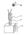
- the total length excluding the length of the muffler cutter portion is an exhaust system for a vehicle in which the muffler cutter 1 is attached to the end of the tail pipe body as shown in FIG.
- the length L of the tail pipe T excluding the muffler cutter 1 portion is meant.
- the muffler cutter of the present invention when the total length excluding the length of the muffler cutter is within the above range, the muffler cutter of the present invention and the sound quality improvement effect of the exhaust sound are appropriately exhibited. be able to.
- the attachment of the muffler cutter to the tail pipe can be performed by welding or the like as appropriate.
- the attachment may be performed at the time of assembly of the vehicle in the factory, or at any time after the vehicle is shipped from the factory. Good.
- the present invention it is possible to selectively reduce only high-frequency sound that is annoying to humans, and in particular, to selectively improve the volume of low-frequency sound that occurs during idling, thereby providing excellent heat insulation and noise reduction and exhaust sound. It is possible to provide a muffler cutter that can improve the sound quality.
- the exhaust pipe 2 is a punched metal SUS pipe (inner diameter 52 mm, outer diameter 54 mm, thermal conductivity 27 W / () with a plurality of openings provided in the entire side wall in the longitudinal direction. m ⁇ K) (400 ° C.)), and a SUS pipe (inner diameter 66 mm) comprising an upper heat shield 3a and a lower heat shield 3b in which a cylindrical object is halved as a heat shield 3 on the cylinder. And an outer diameter of 68 mm, a thermal conductivity of 27 W / (m ⁇ K) (400 ° C.), and an emissivity of 0.3 at a wavelength of 2 to 15 ⁇ m.
- the upper heat shield 3a and the upper heat shield 3a In a state where the end portions 3c and 3c of the lower heat shield plate 3b are butted together, the sound-absorbing heat insulating material 4 is formed into a tubular shape with the exhaust pipe 2 as shown in FIG.
- the heat insulation plate 3 (3a) is filled in a curved shape, and a part between the exhaust pipe 2 and the tubular heat insulation plate 3 (3b) is filled with a sound absorbing heat insulating material.
- a muffler cutter 1 having a closed space S that is a curved hollow portion and a distance between the exhaust pipe 2 forming the closed space S and the tubular heat shield 3 (3b) being 6 mm is manufactured. did.
- an SUS tube (inner diameter 66 mm, outer diameter 68 mm, thermal conductivity 27 W / (m ⁇ K) (400 ° C.), emissivity 0.3 at a wavelength of 2 to 15 ⁇ m) is prepared as a tail pipe body, and FIG.
- the muffler cutter 1 was welded to the end of the tail pipe body so as to be coaxial with the tail pipe body.
- the total length L of the tail pipe T excluding the muffler cutter 1 portion was 160 mm.
- the exhaust pipe 2 is a punched metal SUS pipe (inner diameter 52 mm, outer diameter 54 mm, thermal conductivity 27 W / () with a plurality of openings provided in the entire side wall in the longitudinal direction. m ⁇ K) (400 ° C.)), and as the heat shield 3 on the cylinder, a SUS tube (inner diameter 86 mm) comprising an upper heat shield 3a and a lower heat shield 3b in which a cylindrical object is halved. And an outer diameter of 88 mm, a thermal conductivity of 27 W / (m ⁇ K) (400 ° C.), and an emissivity of 0.3 at a wavelength of 2 to 15 ⁇ m.
- the upper heat shield 3a and the upper heat shield 3a In a state where the end portions 3c and 3c of the lower heat shield plate 3b are butted together, the sound-absorbing heat insulating material 4 is formed into a tubular shape with the exhaust pipe 2 as shown in FIG.
- the heat insulation plate 3 (3a) is filled in a curved shape, and a part between the exhaust pipe 2 and the tubular heat insulation plate 3 (3b) is filled with a sound absorbing heat insulating material.
- a muffler cutter 1 having a closed space S that is a curved hollow portion and a distance between the exhaust pipe 2 forming the closed space S and the cylindrical heat shield 3 (3b) being 16 mm is manufactured. did.
- a SUS tube (inner diameter 52 mm, outer diameter 54 mm, thermal conductivity 27 W / (m ⁇ K) (400 ° C.), emissivity 0.3 at a wavelength of 2 to 15 ⁇ m) is prepared as a tail pipe body, and FIG.
- the muffler cutter 1 was welded to the end of the tail pipe body so as to be coaxial with the tail pipe body.
- the total length L of the tail pipe T excluding the muffler cutter 1 portion was 160 mm.
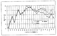
- the sound pressure change was evaluated in the same manner as in Example 1. The results are shown in Table 1 and FIG.
- Example 1 (Comparative Example 1) In Example 1, instead of the muffler cutter 1, a single tube (inner diameter: 52 mm, outer diameter: 54 mm, thermal conductivity: 27 W / (m ⁇ K) (400 ° C.)) was used in the same manner as in Example 1. A tail pipe T was produced. In the obtained tail pipe T, the sound pressure change was evaluated in the same manner as in Example 1. The results are shown in Table 1 and FIG.
- the tail pipe obtained in Example 1 and Example 2 has a coaxial double pipe structure of an exhaust pipe 2 provided with a through hole and a cylindrical heat shield plate 3, and the exhaust pipe is exhausted.
- a comparative example is obtained by partially filling the sound absorbing heat insulating material 4 in a curved shape between the pipe 2 and the tubular heat shield plate 3.
- the sound pressure level can be reduced as compared with the single pipe used in 2 and only the high-frequency sound that is annoying to humans is selectively reduced, and the exhaust pipe 2 provided with a through hole and the cylindrical heat shield plate
- the other part between the three and the third is a curved closed space S, and the distance between the exhaust pipe forming the closed space S and the cylindrical heat shield is controlled to a predetermined distance.
- the sound pressure level in the low frequency region of 100 to 200 Hz from the single tube used Can be above, it can be seen that the volume of low-frequency noise generated at the time of high user preference idling can be selectively emphasized.
- Example 1 A muffler cutter was produced in the same manner as in Example 1 except that the sound-absorbing heat insulating material 4 was not used in Example 1, and then a tail pipe was produced in the same manner as in Example 1. In the obtained tail pipe, the change in sound pressure was evaluated in the same manner as in Example 1. The results are shown in Table 2 and FIG. In Table 2 and FIG. 9, the results of Comparative Example 1 are also shown for comparison.
- Example 2 In Example 1, the sound absorbing heat insulating material 4 is not used, and the plurality of openings provided in the entire side wall in the longitudinal direction of the SUS pipe used as the exhaust pipe 2 are made of aluminum tape (heat-resistant aluminum tape manufactured by Sliontec). A muffler cutter was produced in the same manner as in Example 1 except that the tail pipe was closed, and then a tail pipe was produced in the same manner as in Example 1. In the obtained tail pipe, the change in sound pressure was evaluated in the same manner as in Example 1. The results are shown in Table 2 and FIG.
- the tail pipe obtained in Reference Example 1 is an exhaust pipe having a punching hole as a muffler cutter.
- the sound pressure level tends to increase, particularly in the low frequency region of 100 to 200 Hz. I understand that. *
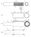
- FIG. 10 is an explanatory view of the muffler cutter produced in this reference example.
- FIG. 10 (a) is a front view of the exhaust pipe 2 (left figure) and a vertical sectional view taken along the line dd ′ of the front view (FIG. 10).
- FIG. 10 (b) shows a front view (left view) of the tubular heat shield 3 and a vertical sectional view (right view) taken along the line ee ′ of the front view.
- FIG. 10C is a front view of the muffler cutter in which the tubular heat shield plate 3 shown in FIG. 10B is coaxially fixed to the exhaust pipe 2 shown in FIG. ) And a front sectional view taken along line ff ′ (right diagram), FIG.
- FIG. 10 (d) shows a vertical sectional view along the longitudinal direction of the muffler cutter shown in FIG. 10 (c).
- a SUS single tube outer diameter 54 mm, plate thickness 0.4 mm, length 340 mm, thermal conductivity 27 W / (m ⁇ K) (400 ° C.)
- a punching metal-like exhaust pipe 2 is formed at one end of the single pipe by providing 576 circular through holes (diameter 3 mm) at intervals of 5 mm on the entire side wall in the longitudinal direction. did.
- FIG. 10 (a) shows a SUS single tube (outer diameter 54 mm, plate thickness 0.4 mm, length 340 mm, thermal conductivity 27 W / (m ⁇ K) (400 ° C.)
- an SUS tube (outer diameter 72 mm, plate thickness 1.0 mm, thermal conductivity 27 W / (m ⁇ K) having a fastening fixing ear M. ) (400 ° C.) emissivity 0.3 at a wavelength of 2 to 15 ⁇ m) and two aluminum ring spacers (outer diameter 70 mm, inner diameter 54 mm, thickness 10 mm) were prepared.
- a tubular heat shield plate 3 is arranged on the outer surface of the exhaust pipe 2 via a ring-shaped spacer s, and then provided on the heat shield plate 3.
- the exhaust pipe 2 and the tubular heat shield plate 3 are connected to the end of the tail pipe T at a distance of 16 mm by tightening and fixing the bolts in the bolt holes provided in the ear M provided in the hot plate 3.
- a muffler cutter 1 fixed while being separated was produced.
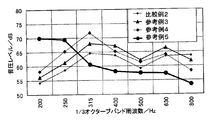
- the sound pressure change was evaluated in the same manner as in Reference Example 3. The results are shown in Table 3 and FIG.
- the exhaust pipe 2 and the cylindrical heat shield plate 3 are connected to the end of the tail pipe T at a distance of 45 mm by tightening and fixing the bolts in the bolt holes provided in the ears M provided in the hot plate 3.
- a muffler cutter 1 fixed while being separated was produced.
- the sound pressure change was evaluated in the same manner as in Reference Example 3. The results are shown in Table 3 and FIG.
- the tail pipes obtained in Reference Example 3 to Reference Example 5 have a coaxial double pipe structure of an exhaust pipe 2 provided with a through hole and a cylindrical heat shield plate 3.
- the sound pressure level can be reduced as compared with the single tube used in Comparative Example 2, and only the high frequency sound that is annoying to humans is selectively reduced, and the exhaust pipe 2 and Comparative Example 2 by providing a curved closed space between the tubular heat shield plate 3 and controlling the distance between the exhaust pipe forming the closed space and the tubular heat shield plate to a predetermined distance. It can be seen that the sound pressure level can be improved in the low frequency region of 200 Hz as compared with the single tube used in the above, and the volume of the low frequency sound generated during idling with high user preference can be selectively emphasized.
- Reference Example 6 In Reference Example 5, except that a SUS single tube (outer diameter 54 mm, plate thickness 1.0 mm, length 340 mm, thermal conductivity 27 W / (m ⁇ K) (400 ° C.)) was not provided with a circular through hole.
- a muffler cutter 1 in which the exhaust pipe 2 and the tubular heat shield 3 were fixed to the end of the tail pipe T while being separated by a distance of 45 mm was produced.
- the sound pressure change was evaluated in the same manner as in Reference Example 3. The results are shown in Table 4 and FIG. In Table 4 and FIG. 13, the results of Reference Example 5 and Comparative Example 2 are also shown for comparison.
- FIG. 7 In Reference Example 5, at one end of a SUS single tube (outer diameter 54 mm, plate thickness 1.0 mm, length 340 mm, thermal conductivity 27 W / (m ⁇ K) (400 ° C.)), FIG. As shown in Fig. 5, the reference example is used except that 288 circular through holes (diameter 3 mm) are provided at intervals of 5 mm on the entire side wall on the upstream side (exhaust gas inflow side) of the exhaust pipe 2. 5, a muffler cutter 1 in which the exhaust pipe 2 and the cylindrical heat shield 3 were fixed to the end of the tail pipe T while being separated by a distance of 45 mm was produced. In the obtained tail pipe T, the sound pressure change was evaluated in the same manner as in Reference Example 3. The results are shown in Table 4 and FIG.
- FIG. 5 In Reference Example 5, at one end of a SUS single tube (outer diameter 54 mm, plate thickness 1.0 mm, length 340 mm, thermal conductivity 27 W / (m ⁇ K) (400 ° C.)), FIG. As shown in FIG. 5, the reference example is used except that 288 circular through holes (diameter 3 mm) are provided at intervals of 5 mm on the entire downstream side wall of the exhaust pipe 2 (exhaust gas outflow side). 5, a muffler cutter 1 in which the exhaust pipe 2 and the cylindrical heat shield 3 were fixed to the end of the tail pipe T while being separated by a distance of 45 mm was produced. In the obtained tail pipe T, the sound pressure change was evaluated in the same manner as in Reference Example 3. The results are shown in Table 4 and FIG.
- the tail pipe obtained in Reference Example 6 has a coaxial double pipe structure of the exhaust pipe 2 having no through hole and the cylindrical heat shield plate 3. It can be seen that the sound pressure level can be improved over the entire measurement frequency than the single tube used in Comparative Example 2.
- the tail pipes obtained in Reference Example 5, Reference Example 7 and Reference Example 8 are exhaust pipes having a coaxial double pipe structure of an exhaust pipe 2 having a through hole and a cylindrical heat shield. Comparative Example 2 and Reference Example in the high frequency region of 800 Hz by controlling the distance between the exhaust pipe formed between the tube 2 and the tubular heat shield plate 3 and the tubular heat shield plate to a predetermined distance.
- the sound pressure level can be reduced more than 6 and only high-frequency sound that is harsh to human beings can be selectively reduced, and the sound pressure level can be improved in the low frequency region of 200 Hz than Comparative Example 2 and Reference Example 6. It can be seen that the volume of low frequency sound generated during idling with high user preference can be selectively emphasized. Furthermore, when comparing the tail pipe obtained in Reference Example 7 and the tail pipe obtained in Reference Example 8, the tail pipe obtained in Reference Example 7 is compared with the tail pipe obtained in Reference Example 8, It can be seen that the sound pressure level is lowered overall.
- the muffler cutter 1 obtained in Example 1 can sufficiently reduce the temperature rise of the bumper surface as compared with a hollow double tube not filled with a sound absorbing heat insulating material. . Moreover, from Table 5, the muffler cutter 1 obtained in Example 1 is formed by filling a sound-absorbing heat insulating material only in a part between the exhaust pipe and the tubular heat shield. Regardless, the heat radiation to the bumper side is suppressed to the same level or more as a muffler cutter (full-filled double pipe) in which the entire space formed between the exhaust pipe and the cylindrical heat shield is filled with sound-absorbing heat insulating material. And it turns out that the temperature rise of a bumper surface can be reduced.
- the present invention it is possible to provide a muffler cutter that is excellent in heat insulation and noise reduction and can improve the sound quality of exhaust sound. Moreover, according to this invention, the tail pipe formed by mounting
Landscapes
- Engineering & Computer Science (AREA)
- Chemical & Material Sciences (AREA)
- Combustion & Propulsion (AREA)
- Mechanical Engineering (AREA)
- General Engineering & Computer Science (AREA)
- Exhaust Silencers (AREA)
Abstract
La présente invention concerne un embout d'échappement possédant d'excellentes propriétés d'isolation thermique et d'atténuation du son, et pouvant améliorer la qualité sonore d'un échappement. Cet embout d'échappement (1), qui est monté sur un tuyau d'échappement arrière d'un système d'échappement d'un véhicule, est caractérisé en ce qu'il est pourvu d'un tuyau d'échappement (2) dans la paroi latérale duquel sont formés plusieurs trous traversants, d'une plaque de protection thermique cylindrique (3) placée sur l'extérieur et coaxiale avec le tuyau d'échappement, et d'un matériau isolant thermique absorbant les sons (4) placé dans l'intervalle entre le tuyau d'échappement et la plaque de protection thermique cylindrique, le matériau isolant thermique absorbant les sons ne remplissant qu'une partie de l'intervalle entre le tuyau d'échappement et la plaque de protection thermique cylindrique selon une forme courbe, et un espace fermé courbe (S) étant formé dans l'autre partie de l'intervalle entre le tuyau d'échappement et la plaque de protection thermique cylindrique, et la distance entre le tuyau d'échappement et la plaque de protection thermique cylindrique formant l'espace fermé étant de 1 à 50 mm.
Priority Applications (2)
| Application Number | Priority Date | Filing Date | Title |
|---|---|---|---|
| EP14785637.1A EP2987979B1 (fr) | 2013-04-15 | 2014-04-09 | Embout d'échappement |
| US14/784,332 US9810117B2 (en) | 2013-04-15 | 2014-04-09 | Muffler cutter |
Applications Claiming Priority (2)
| Application Number | Priority Date | Filing Date | Title |
|---|---|---|---|
| JP2013085064A JP6153371B2 (ja) | 2013-04-15 | 2013-04-15 | マフラーカッター |
| JP2013-085064 | 2013-04-15 |
Publications (1)
| Publication Number | Publication Date |
|---|---|
| WO2014171380A1 true WO2014171380A1 (fr) | 2014-10-23 |
Family
ID=51731323
Family Applications (1)
| Application Number | Title | Priority Date | Filing Date |
|---|---|---|---|
| PCT/JP2014/060314 Ceased WO2014171380A1 (fr) | 2013-04-15 | 2014-04-09 | Embout d'échappement |
Country Status (4)
| Country | Link |
|---|---|
| US (1) | US9810117B2 (fr) |
| EP (1) | EP2987979B1 (fr) |
| JP (1) | JP6153371B2 (fr) |
| WO (1) | WO2014171380A1 (fr) |
Cited By (2)
| Publication number | Priority date | Publication date | Assignee | Title |
|---|---|---|---|---|
| CN104847449A (zh) * | 2015-04-13 | 2015-08-19 | 成都陵川特种工业有限责任公司 | 一种尾气排放管的噪音减弱处理方法 |
| CN107503924A (zh) * | 2017-08-15 | 2017-12-22 | 深圳市合精密泵业科技有限公司 | 一种压电气泵 |
Families Citing this family (6)
| Publication number | Priority date | Publication date | Assignee | Title |
|---|---|---|---|---|
| DE102014217058A1 (de) * | 2014-08-27 | 2016-03-03 | Eberspächer Exhaust Technology GmbH & Co. KG | Schalldämpfer |
| KR101503049B1 (ko) * | 2014-11-19 | 2015-03-19 | 주식회사 동성정공 | 단열층이 커버링된 배기파이프의 제조방법 |
| JP6885113B2 (ja) * | 2017-03-08 | 2021-06-09 | 三菱自動車工業株式会社 | 排気管構造 |
| US10900407B2 (en) * | 2019-01-17 | 2021-01-26 | Honda Motor Co., Ltd. | Muffler with internal gap heat shield |
| US11453353B2 (en) | 2019-10-31 | 2022-09-27 | Honda Motor Co., Ltd | High temperature heat shield for a tail gate |
| DE102019132097A1 (de) * | 2019-11-27 | 2021-05-27 | Eberspächer Exhaust Technology GmbH | Abgasschalldämpfer |
Citations (7)
| Publication number | Priority date | Publication date | Assignee | Title |
|---|---|---|---|---|
| JPH0239533U (fr) * | 1988-09-07 | 1990-03-16 | ||
| US6267199B1 (en) * | 1999-10-15 | 2001-07-31 | Sound Ware Industry Co., Ltd. | Automobile exhaust tube |
| JP2002256840A (ja) * | 2001-02-23 | 2002-09-11 | Puroto:Kk | マフラ |
| US20040206573A1 (en) * | 2002-11-27 | 2004-10-21 | Hsu Henry T. H. | Muffler exhaust tip |
| JP2005054587A (ja) * | 2003-08-04 | 2005-03-03 | Hino Motors Ltd | 排ガス処理物品用外装品 |
| JP2008106630A (ja) * | 2006-10-23 | 2008-05-08 | Toyota Motor Corp | 車載エンジンの排気装置 |
| JP2008190371A (ja) | 2007-02-02 | 2008-08-21 | Calsonic Kansei Corp | 排気系のフィニッシャー構造 |
Family Cites Families (23)
| Publication number | Priority date | Publication date | Assignee | Title |
|---|---|---|---|---|
| FR816537A (fr) | 1935-12-07 | 1937-08-10 | Silencieux | |
| US3114617A (en) * | 1960-04-25 | 1963-12-17 | Lester M Rowe | Exhaust pipe attachment for filtering exhaust gases |
| US3404750A (en) * | 1966-07-14 | 1968-10-08 | Walker Mfg Co | Combination tailpipe spout and silencer |
| US3752260A (en) * | 1971-07-15 | 1973-08-14 | Tenneco Inc | Air rush silencer |
| FR2241987A5 (fr) * | 1973-08-22 | 1975-03-21 | Citroen Sa | |
| SE7611638L (sv) * | 1975-10-21 | 1977-04-22 | Bremshey Ag | Dubbelveggig verme- och ljudisolerande rorledning, serskilt avgasror |
| JPS60128929U (ja) * | 1984-02-08 | 1985-08-29 | 日産自動車株式会社 | エンジン排気系の端部構造 |
| DE19627079A1 (de) * | 1996-07-05 | 1998-01-08 | Eberspaecher J Gmbh & Co | Absorptions-/Reflexions-Schalldämpfer |
| US5726398A (en) * | 1997-02-26 | 1998-03-10 | Ap Parts Manufacturing Company | Automotive bumper and muffler combination |
| DE19722037A1 (de) * | 1997-05-27 | 1998-12-03 | Hecralmat Fa | Hitzeschild mit Schallisolierung |
| CH692946A5 (de) * | 1998-03-12 | 2002-12-31 | Rieter Automotive Int Ag | Schwingungsdämpfende, geräuschmindernde und wärmeabschirmende Fahrzeugaussenverkleidung. |
| JP2000190744A (ja) * | 1998-12-25 | 2000-07-11 | Unipres Corp | 遮熱吸音機能を備えた排気装置 |
| US6408980B1 (en) * | 2000-03-02 | 2002-06-25 | Mark W. Dooley | Exhaust pipe and muffler for motorcycle that does not heat discolor |
| DE50110583D1 (de) * | 2000-04-14 | 2006-09-14 | Eberspaecher J Gmbh & Co | Abgas-Schalldämpfer in Mehrkammerbauweise |
| US7273129B2 (en) * | 2003-09-05 | 2007-09-25 | Faurecia Exhaust Systems, Inc. | Muffler with internal heat shield |
| DE102004062632A1 (de) * | 2004-12-24 | 2006-07-06 | Volkswagen Ag | Wärmeabschirmung für ein abgasführendes Element |
| JP5052038B2 (ja) * | 2006-05-19 | 2012-10-17 | トヨタ自動車株式会社 | 燃料電池用消音器 |
| DE102007010814A1 (de) * | 2007-03-06 | 2008-09-11 | Arvinmeritor Emissions Technologies Gmbh | Schalldämpfer-Dämmelement, Schalldämpfer sowie Verfahren zur Herstellung eines Schalldämpfers |
| JP5275893B2 (ja) * | 2009-05-15 | 2013-08-28 | 株式会社神戸製鋼所 | ヒートインシュレータの取付構造 |
| JP2011064192A (ja) * | 2009-08-21 | 2011-03-31 | Nichias Corp | 自動車用排気管 |
| JP5782316B2 (ja) | 2011-07-12 | 2015-09-24 | ニチアス株式会社 | 配管カバー、配管構造体および車輌 |
| KR101326511B1 (ko) * | 2011-09-01 | 2013-11-08 | 기아자동차주식회사 | 자동차용 배기계 머플러 |
| JP5775794B2 (ja) * | 2011-11-08 | 2015-09-09 | ニチアス株式会社 | マフラーカッター |
-
2013
- 2013-04-15 JP JP2013085064A patent/JP6153371B2/ja not_active Expired - Fee Related
-
2014
- 2014-04-09 EP EP14785637.1A patent/EP2987979B1/fr not_active Not-in-force
- 2014-04-09 US US14/784,332 patent/US9810117B2/en not_active Expired - Fee Related
- 2014-04-09 WO PCT/JP2014/060314 patent/WO2014171380A1/fr not_active Ceased
Patent Citations (7)
| Publication number | Priority date | Publication date | Assignee | Title |
|---|---|---|---|---|
| JPH0239533U (fr) * | 1988-09-07 | 1990-03-16 | ||
| US6267199B1 (en) * | 1999-10-15 | 2001-07-31 | Sound Ware Industry Co., Ltd. | Automobile exhaust tube |
| JP2002256840A (ja) * | 2001-02-23 | 2002-09-11 | Puroto:Kk | マフラ |
| US20040206573A1 (en) * | 2002-11-27 | 2004-10-21 | Hsu Henry T. H. | Muffler exhaust tip |
| JP2005054587A (ja) * | 2003-08-04 | 2005-03-03 | Hino Motors Ltd | 排ガス処理物品用外装品 |
| JP2008106630A (ja) * | 2006-10-23 | 2008-05-08 | Toyota Motor Corp | 車載エンジンの排気装置 |
| JP2008190371A (ja) | 2007-02-02 | 2008-08-21 | Calsonic Kansei Corp | 排気系のフィニッシャー構造 |
Non-Patent Citations (1)
| Title |
|---|
| See also references of EP2987979A4 |
Cited By (2)
| Publication number | Priority date | Publication date | Assignee | Title |
|---|---|---|---|---|
| CN104847449A (zh) * | 2015-04-13 | 2015-08-19 | 成都陵川特种工业有限责任公司 | 一种尾气排放管的噪音减弱处理方法 |
| CN107503924A (zh) * | 2017-08-15 | 2017-12-22 | 深圳市合精密泵业科技有限公司 | 一种压电气泵 |
Also Published As
| Publication number | Publication date |
|---|---|
| US20160053642A1 (en) | 2016-02-25 |
| EP2987979B1 (fr) | 2018-07-11 |
| EP2987979A1 (fr) | 2016-02-24 |
| EP2987979A4 (fr) | 2016-12-14 |
| JP2014206131A (ja) | 2014-10-30 |
| US9810117B2 (en) | 2017-11-07 |
| JP6153371B2 (ja) | 2017-06-28 |
Similar Documents
| Publication | Publication Date | Title |
|---|---|---|
| JP6153371B2 (ja) | マフラーカッター | |
| US4410013A (en) | Composite dual tubing | |
| EP0047526B1 (fr) | Conduite composite à double paroi | |
| KR20140080644A (ko) | 듀얼 머플러 | |
| JP2011032924A (ja) | 車両用エンジンの排気管に設けられる消音器 | |
| WO2013008810A1 (fr) | Revêtement de tuyau, structure de tuyau et véhicule | |
| CN106121774A (zh) | 一种低噪声复合式多腔排气消声器 | |
| CN106468197A (zh) | 一种宽频降噪消声器 | |
| CN216590546U (zh) | 一种超构消声器 | |
| CN206111279U (zh) | 汽车前消声器结构 | |
| JP5775794B2 (ja) | マフラーカッター | |
| JP2016023565A (ja) | 車輌用排気管および車輌用排気管の製造方法 | |
| CN103953418B (zh) | 一种多级复合消音的消声器及其制备方法 | |
| JP2002195021A (ja) | 排気消音器 | |
| CN218894698U (zh) | 汽车消声器隔热罩 | |
| JPS5939632B2 (ja) | 制振2重鋼管 | |
| JP2015194335A (ja) | 消音チャンバ | |
| CN207934955U (zh) | 消声隔热罩及排气管 | |
| KR101443305B1 (ko) | 상쇄간섭형 배기소음기 | |
| JPH0122445B2 (fr) | ||
| JP2016108957A (ja) | 消音器 | |
| CN207905887U (zh) | 一种汽车消音器 | |
| FI121029B (fi) | Äänenvaimentaja | |
| CN118088290A (zh) | 消声器总成及车辆 | |
| JPS6137781Y2 (fr) |
Legal Events
| Date | Code | Title | Description |
|---|---|---|---|
| 121 | Ep: the epo has been informed by wipo that ep was designated in this application |
Ref document number: 14785637 Country of ref document: EP Kind code of ref document: A1 |
|
| WWE | Wipo information: entry into national phase |
Ref document number: 2014785637 Country of ref document: EP |
|
| WWE | Wipo information: entry into national phase |
Ref document number: 14784332 Country of ref document: US |
|
| NENP | Non-entry into the national phase |
Ref country code: DE |