WO2014171408A1 - Dispositif de commutation - Google Patents
Dispositif de commutation Download PDFInfo
- Publication number
- WO2014171408A1 WO2014171408A1 PCT/JP2014/060504 JP2014060504W WO2014171408A1 WO 2014171408 A1 WO2014171408 A1 WO 2014171408A1 JP 2014060504 W JP2014060504 W JP 2014060504W WO 2014171408 A1 WO2014171408 A1 WO 2014171408A1
- Authority
- WO
- WIPO (PCT)
- Prior art keywords
- operation unit
- magnetic member
- unit
- pushing
- switch
- Prior art date
- Legal status (The legal status is an assumption and is not a legal conclusion. Google has not performed a legal analysis and makes no representation as to the accuracy of the status listed.)
- Ceased
Links
Images














Classifications
-
- H—ELECTRICITY
- H01—ELECTRIC ELEMENTS
- H01H—ELECTRIC SWITCHES; RELAYS; SELECTORS; EMERGENCY PROTECTIVE DEVICES
- H01H13/00—Switches having rectilinearly-movable operating part or parts adapted for pushing or pulling in one direction only, e.g. push-button switch
- H01H13/70—Switches having rectilinearly-movable operating part or parts adapted for pushing or pulling in one direction only, e.g. push-button switch having a plurality of operating members associated with different sets of contacts, e.g. keyboard
- H01H13/702—Switches having rectilinearly-movable operating part or parts adapted for pushing or pulling in one direction only, e.g. push-button switch having a plurality of operating members associated with different sets of contacts, e.g. keyboard with contacts carried by or formed from layers in a multilayer structure, e.g. membrane switches
- H01H13/705—Switches having rectilinearly-movable operating part or parts adapted for pushing or pulling in one direction only, e.g. push-button switch having a plurality of operating members associated with different sets of contacts, e.g. keyboard with contacts carried by or formed from layers in a multilayer structure, e.g. membrane switches characterised by construction, mounting or arrangement of operating parts, e.g. push-buttons or keys
-
- H—ELECTRICITY
- H01—ELECTRIC ELEMENTS
- H01H—ELECTRIC SWITCHES; RELAYS; SELECTORS; EMERGENCY PROTECTIVE DEVICES
- H01H13/00—Switches having rectilinearly-movable operating part or parts adapted for pushing or pulling in one direction only, e.g. push-button switch
- H01H13/02—Details
- H01H13/12—Movable parts; Contacts mounted thereon
- H01H13/20—Driving mechanisms
- H01H13/22—Driving mechanisms acting with snap action
-
- H—ELECTRICITY
- H01—ELECTRIC ELEMENTS
- H01H—ELECTRIC SWITCHES; RELAYS; SELECTORS; EMERGENCY PROTECTIVE DEVICES
- H01H5/00—Snap-action arrangements, i.e. in which during a single opening operation or a single closing operation energy is first stored and then released to produce or assist the contact movement
- H01H5/02—Energy stored by the attraction or repulsion of magnetic parts
-
- H—ELECTRICITY
- H03—ELECTRONIC CIRCUITRY
- H03K—PULSE TECHNIQUE
- H03K17/00—Electronic switching or gating, i.e. not by contact-making and –breaking
- H03K17/94—Electronic switching or gating, i.e. not by contact-making and –breaking characterised by the way in which the control signals are generated
- H03K17/965—Switches controlled by moving an element forming part of the switch
-
- H—ELECTRICITY
- H03—ELECTRONIC CIRCUITRY
- H03K—PULSE TECHNIQUE
- H03K17/00—Electronic switching or gating, i.e. not by contact-making and –breaking
- H03K17/94—Electronic switching or gating, i.e. not by contact-making and –breaking characterised by the way in which the control signals are generated
- H03K17/965—Switches controlled by moving an element forming part of the switch
- H03K17/975—Switches controlled by moving an element forming part of the switch using a capacitive movable element
-
- H—ELECTRICITY
- H01—ELECTRIC ELEMENTS
- H01H—ELECTRIC SWITCHES; RELAYS; SELECTORS; EMERGENCY PROTECTIVE DEVICES
- H01H2215/00—Tactile feedback
- H01H2215/034—Separate snap action
- H01H2215/042—Permanent magnets
-
- H—ELECTRICITY
- H01—ELECTRIC ELEMENTS
- H01H—ELECTRIC SWITCHES; RELAYS; SELECTORS; EMERGENCY PROTECTIVE DEVICES
- H01H2221/00—Actuators
- H01H2221/036—Return force
- H01H2221/04—Return force magnetic
-
- H—ELECTRICITY
- H01—ELECTRIC ELEMENTS
- H01H—ELECTRIC SWITCHES; RELAYS; SELECTORS; EMERGENCY PROTECTIVE DEVICES
- H01H2223/00—Casings
- H01H2223/01—Mounting on appliance
- H01H2223/012—Snap mounting
-
- H—ELECTRICITY
- H01—ELECTRIC ELEMENTS
- H01H—ELECTRIC SWITCHES; RELAYS; SELECTORS; EMERGENCY PROTECTIVE DEVICES
- H01H2227/00—Dimensions; Characteristics
- H01H2227/032—Operating force
- H01H2227/034—Regulation of operating force
-
- H—ELECTRICITY
- H01—ELECTRIC ELEMENTS
- H01H—ELECTRIC SWITCHES; RELAYS; SELECTORS; EMERGENCY PROTECTIVE DEVICES
- H01H2233/00—Key modules
- H01H2233/03—Key modules mounted on support plate or frame
- H01H2233/034—Snap coupling
-
- H—ELECTRICITY
- H01—ELECTRIC ELEMENTS
- H01H—ELECTRIC SWITCHES; RELAYS; SELECTORS; EMERGENCY PROTECTIVE DEVICES
- H01H23/00—Tumbler or rocker switches, i.e. switches characterised by being operated by rocking an operating member in the form of a rocker button
- H01H23/02—Details
- H01H23/12—Movable parts; Contacts mounted thereon
- H01H23/16—Driving mechanisms
- H01H23/20—Driving mechanisms having snap action
-
- H—ELECTRICITY
- H01—ELECTRIC ELEMENTS
- H01H—ELECTRIC SWITCHES; RELAYS; SELECTORS; EMERGENCY PROTECTIVE DEVICES
- H01H23/00—Tumbler or rocker switches, i.e. switches characterised by being operated by rocking an operating member in the form of a rocker button
- H01H23/28—Tumbler or rocker switches, i.e. switches characterised by being operated by rocking an operating member in the form of a rocker button with three operating positions
- H01H23/30—Tumbler or rocker switches, i.e. switches characterised by being operated by rocking an operating member in the form of a rocker button with three operating positions with stable centre positions and one or both end positions unstable
-
- H—ELECTRICITY
- H01—ELECTRIC ELEMENTS
- H01H—ELECTRIC SWITCHES; RELAYS; SELECTORS; EMERGENCY PROTECTIVE DEVICES
- H01H25/00—Switches with compound movement of handle or other operating part
- H01H25/04—Operating part movable angularly in more than one plane, e.g. joystick
- H01H25/041—Operating part movable angularly in more than one plane, e.g. joystick having a generally flat operating member depressible at different locations to operate different controls
Definitions
- the present invention relates to a switch device.
- Japanese Patent Application Laid-Open No. 9-265873 discloses a thin switch including a touch panel and an operation mechanism unit disposed on the touch panel.
- the operation mechanism unit includes a push button, a movable side magnetic body provided at an outer end portion of the push button, and a fixed side magnetic body disposed above the movable side magnetic body. Adsorb to each other.
- a click feeling can be obtained when the adsorption of both magnetic bodies is released by pressing the push button.
- a protrusion is provided on the lower surface side of the line that divides the push button into two areas, and two switch parts are provided in portions below the two areas, whereby the two switch parts are operated separately. Techniques for doing this are also disclosed.
- the present invention is directed to a switch device, and an object of the present invention is to easily change the push-in amount of the operation unit while using common parts in the switch device that generates a click feeling.
- the switch device includes an operation unit, a support structure that supports the operation unit so as to be movable between a normal position and a push-in position, and a position holding unit that holds the operation unit at the normal position.
- a detection unit that is provided in the support structure and detects the push of the operation unit to the push-in position, and the support structure is located above an operation end that is a side end of the operation unit.
- a first magnetic member formed of a magnetic material provided at one of the facing portion and the operation end portion, and the facing portion and the operation end portion.
- a second magnetic member provided opposite to the first magnetic member at the other part of the first magnetic member and holding the operating portion at the steady position by a magnetic attraction generated between the first magnetic member and the first magnetic member; And the one part is the first magnetic part.
- the pushing amount of the operation unit can be easily changed while using the common parts by changing the mounting position where the first magnetic member is mounted.
- the plurality of attachment positions have the same push amount when the first magnetic member is attached as in the case where the first magnetic member is attached to the one attachment position. Including other mounting positions. As a result, the number of first magnetic members can be changed to easily change the force required to push the operating portion.
- the plurality of attachment positions have the same push amount when the first magnetic member is attached as in the case where the first magnetic member is attached to the other attachment position. Including other mounting positions. Thereby, in each of the two pushing amounts, the force required to push the operation unit can be easily changed.
- the detection unit has a plurality of detection elements, and when the operation unit is pushed into the push-in position, the depression of the operation unit is one detection of the detection unit.
- the operation unit is further pushed in by being detected by an element, a part of the operation unit or a part of the detection unit is elastically deformed, and further pushing of the operation unit is caused by another of the detection unit. It is detected by the detection element.
- the detection unit has a plurality of detection elements, and a protrusion is provided at a position facing the lower surface of the operation unit or the lower surface of the operation unit.
- FIG. 1 It is a top view which shows the switch apparatus which concerns on 1st Embodiment. It is sectional drawing which shows a switch apparatus. It is sectional drawing which shows a switch apparatus. It is sectional drawing which shows a switch apparatus. It is a figure which shows the switch apparatus in which an operation part is located in a pushing position. It is a figure which shows the switch apparatus in which an operation part is located in a pushing position. It is a figure which shows the switch apparatus which changed the pushing amount. It is a figure which shows the switch apparatus which changed the pushing amount. It is a figure which shows the switch apparatus in which an operation part is located in a pushing position. It is a figure which shows the switch apparatus in which an operation part is located in a pushing position. It is a figure which shows the switch apparatus in which an operation part is located in a pushing position. It is a figure which shows the switch apparatus which changed the force required to push in an operation part.
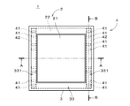
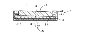
- FIG. 1 is a plan view showing a switch device 1 according to a first embodiment of the present invention
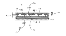
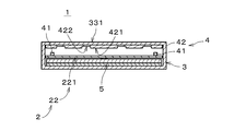
- FIG. 2 is a cross-sectional view of the switch device 1 at the position of arrow AA in FIG. 1
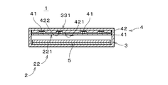
- FIG. FIG. 3 is a cross-sectional view of the switch device 1 at a position indicated by an arrow BB in FIG. 2 illustrates a magnetic member 41 described later behind the cut surface
- FIG. 3 illustrates an input projection 211 of the operation unit 2 described later behind the cut surface (the same applies to other corresponding drawings). ).
- the switch device 1 is a thin push button switch, and is provided in various devices.
- the switch device 1 includes an operation unit 2, a support structure 3 that supports the operation unit 2 movably between a later-described steady position and a push-in position, and the operation unit 2.
- maintained in a steady position and the detection part 5 which detects pushing to the pushing position of the operation part 2 are provided.
- the operation unit 2 can move in the vertical direction of FIGS. 2 and 3 (and the direction perpendicular to the paper surface of FIG. 1).
- the vertical direction of FIGS. This is simply called the up-down direction.
- the vertical direction does not need to be parallel to the gravity direction, and may be parallel to the horizontal direction, for example.
- the operation unit 2 includes an operation unit main body 21 and an operation end 22 that is a side end of the operation unit 2.
- the shape of the operation unit main body 21 when viewed along the vertical direction is a rectangle, and the operation end 22 is provided in an annular shape over the entire circumference of the operation unit main body 21.
- the thickness of the operation end 22 is smaller than the thickness of the operation unit main body 21, and the operation end 22 protrudes outward from the side surface of the operation unit main body 21.
- the lower surface of the operation end portion 22 and the lower surface of the operation portion main body 21 are located on the same plane.
- the operation unit 2 has a shape in which the upper part of the outer edge of the thick plate member is cut out.
- the operation part main body 21 and the operation end part 22 are formed with resin as one member, for example.
- the operation end 22 may be provided only on a part of the outer edge of the operation unit main body 21.
- the support structure 3 in the present embodiment is a case that accommodates the operation unit 2, and includes a side surface unit 31 that surrounds the side surface of the operation unit 2, and a bottom surface unit 32 that faces the lower surface of the operation unit 2 via the detection unit 5.
- Have A facing portion 33 that protrudes inward is provided at the upper end of the side surface portion 31 over the entire circumference.
- the facing portion 33 is located above the operation end portion 22 and faces the operation end portion 22 in the vertical direction.
- the side surface portion 31 is close to the outer edge of the operation end portion 22 over the entire circumference, and the inner edge of the facing portion 33 is close to the side surface of the operation portion main body 21 over the entire periphery. Thereby, the vertical movement of the operation unit 2 is guided by the support structure 3.
- the support structure 3 does not necessarily have a case shape, and may be a frame structure or the like.
- a plate-like magnetic member 42 extending along the shape portion 331 is provided.
- the magnetic member 42 is formed of a magnetic material such as iron.
- a plurality of recesses 420 are formed on the lower surface of the magnetic member 42 along the longitudinal direction.
- the depths of the plurality of recesses 420 are constant, and an upper region 422 having a certain height, which is a set of bottom surfaces (upper surfaces) of the recesses 420, and an upper region 422 are formed on the lower surface of the magnetic member 42 in the vertical direction.
- a lower region 421 having a certain height (which may be regarded as a convex region), which is a set of regions to be excluded, is set. That is, unevenness is formed on the lower surface of the magnetic member 42.
- each of the plurality of magnetic members 41 is defined as a first attachment position on the upper surface of the operation linear portion 221 where each magnetic member 41 can be attached to face the lower region 421 of the magnetic member 42. It is attached at one attachment position.
- the fixing of the magnetic member 41 to the operation end portion 22 and the fixing of the magnetic member 42 to the facing portion 33 may be performed by a known method such as adhesion or press-fitting.
- the magnetic member 41 is a permanent magnet, and a magnetic attractive force is generated between the magnetic member 42 and the magnetic member 41. Therefore, in a steady state where the operator does not push in the operation unit 2, as shown in FIG. 3, the plate-like magnetic member 42 on each opposing linear portion 331 and the operation linear shape facing the opposing linear portion 331. The plurality of magnetic members 41 on the portion 221 are attracted. As described above, the operation unit 2 is held at the position shown in FIGS. 2 and 3 (hereinafter referred to as “steady position”) by the position holding unit 4 including the magnetic member 42 and the magnetic member 41.
- the magnetic member 42 may be a permanent magnet, and the magnetic member 41 may be magnetized by the magnetic member 42 to generate a magnetic attractive force therebetween. Further, both of the magnetic members 41 and 42 may be permanent magnets.
- the detection unit 5 includes, for example, a sheet-like tactile switch 51 provided in the support structure 3. As shown in FIGS. 4 and 5, when the operation unit 2 is pushed downward by the operator, the lower surface of the operation unit 2 comes into contact with the tactile switch 51, and the tactile switch 51 pushes the operation unit 2. Detected. Actually, the input protrusion 211 provided on the lower surface of the operation unit 2 contacts the tactile switch 51. In the following description, the position of the operation unit 2 with which the lower part comes into contact with the member below (in this case, the tactile switch 51) is referred to as a “push-in position”.
- the detection unit 5 may be other than a tactile switch, for example, a touch switch, a pressure sensor, or a Hall element or an electromagnetic induction sensor indicated by a two-dot chain line rectangle denoted by reference numeral 52 in FIG. (The same applies to other switch devices).
- a tactile switch for example, a touch switch, a pressure sensor, or a Hall element or an electromagnetic induction sensor indicated by a two-dot chain line rectangle denoted by reference numeral 52 in FIG. (The same applies to other switch devices).
- the magnetism when the operation unit 2 is pushed into the push-in position since the operation unit 2 is located at a steady position where the magnetic member 42 and the magnetic member 41 are attracted, the magnetism when the operation unit 2 is pushed into the push-in position.
- the gap width between the member 42 and the magnetic member 41 becomes the pushing amount (stroke amount) of the operation unit 2.
- the magnetic member 41 faces the lower region 421 of the lower surface of the magnetic member 42 in the vertical direction, and the amount of pressing in the switch device 1 is between the lower region 421 and the upper surface of the magnetic member 41. Is the distance between.
- the pushing amount of the operation unit 2 is indicated by an arrow denoted by reference sign A1.
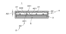
- the magnetic member 41 can be attached to the upper surface 422 of the plate-like magnetic member 42 on the upper surface of the operation line-shaped portion 221 (see FIG. 5).
- Each of the plurality of magnetic members 41 is attached to the second attachment position as shown in FIG.
- the magnetic member 41 attached to the 2nd attachment position is shown with the dashed-two dotted line.
- the operation end 22 which is a side end of the operation unit 2 has the first attachment position and the second attachment position to which the magnetic member 41 can be attached.
- the position and the second attachment position are respectively opposed to the lower region 421 and the upper region 422 having different vertical heights (positions) on the lower surface of the plate-like magnetic member 42.
- a plurality of first attachment positions are provided at the operation end 22. That is, the plurality of attachment positions at the operation end 22 include one first attachment position and the other first attachment position where the push-in amount when the magnetic member 41 is attached is the same. As a result, the number of magnetic members 41 can be changed, and the force required to push the operation unit 2 can be easily changed.
- the operation end 22 is provided with a plurality of second attachment positions. In other words, the plurality of attachment positions at the operation end 22 include one second attachment position and the other second attachment position where the pushing amount when the magnetic member 41 is attached is the same. As a result, the force required to push the operating portion 2 can be easily changed in each of the two push-in amounts corresponding to the first attachment position and the second attachment position, respectively.
- the push amount of the operation portion 2 or the force required for push is changed not only at the time of manufacturing the switch device 1 but also the switch. You may perform in the state with which the apparatus 1 was mounted
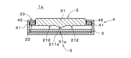
- FIG. 12 is a cross-sectional view of the switch device 1a according to the second embodiment of the present invention, and corresponds to FIG.
- the structure of the operation unit 2 is different from that of the switch device 1 of FIG.
- the detection unit 5 includes a capacitive touch switch 51a.
- Other components are the same as those in FIG. 2, and the same components are denoted by the same reference numerals.
- a relatively large input protrusion 211a is provided on the lower surface.
- the cross-sectional area of the input projection 211a perpendicular to the vertical direction gradually decreases from the lower surface of the operation unit main body 21 downward.
- the operation portion main body 21 and the input projection 211a are formed of an elastic material such as conductive rubber.
- the touch switch 51a is a position input device capable of multipoint detection, and can be regarded as having a plurality of detection elements.
- the switch device 1a that detects the pushing position and the second pushing position of the operation unit 2 can be used, for example, for speed change (high speed and low speed change) during inching operation of a motor or the like.
- the detection unit 5 has a plurality of detection elements, and when the operation unit 2 is pushed into the pushing position, the pushing of the operation unit 2 is one of the detection units 5.
- the switch device 1a implements a three-position switch that detects a two-stage pushing position.
- the switch device 1 of the first embodiment by changing the mounting position to which the magnetic member 41 is mounted, it is possible to easily change the pushing amount of the operation unit 2 while using common parts. it can. Furthermore, by changing the number of the magnetic members 41, it is possible to easily change the force required to push the operation unit 2.
- a transparent conductive sheet formed with a protrusion by embossing is used as a conductive operation unit body 21 (with a low elastic modulus).
- the operation unit 2 is formed by pasting it on the lower surface (the same applies to the example of FIG. 15). In this case, when the operation unit 2 is pushed into the push-in position, the projection of the transparent conductive sheet comes into contact with one detection element of the touch switch 51a, and when the operation unit 2 is further pushed in, the projection is elastic. It is deformed (collapsed) and comes into contact with detection elements around the detection element in the touch switch 51a.
- the operation part 2 may be formed as one member by transparent conductive rubber or the like.
- the colored operation part 2 of FIG. 12 may be formed using the embossed conductive sheet.
- FIG. 15 is a diagram showing another example of the switch device 1a.
- a plurality of input protrusions 211a and 212 are provided on the lower surface of the operation unit main body 21 of the operation unit 2. With respect to the vertical direction, the height of each input protrusion 212 is smaller than that of the input protrusion 211a.
- the operation unit 2 moves to a depressing position where the vicinity of the tip of the input projection 211a contacts the touch switch 51a. Thereby, pushing to the pushing position of the operation part 2 is detected by one detection element of the touch switch 51a.
- the input projection 211a is mainly elastically deformed, and the operation unit 2 moves to the second push position shown in FIG.
- the vicinity of the tip of each input projection 212 is in contact with the touch switch 51a, and further pressing of the operation unit 2 is detected by another detection element close to the detection element.
- the push-in position in two stages can be detected also by the switch device 1a of FIG.
- elastic members having different heights are provided at positions corresponding to the plurality of input projections 211a and 212 on the upper surface of the touch switch 51a (detection unit 5) in the switch device 1a of FIG.
- the plurality of input protrusions 211a and 212 may be omitted.
- the operation unit 2 when the operation unit 2 is pushed into the pushing position, the operation unit 2 comes into contact with the higher elastic member, and the pushing of the operation unit 2 is detected by one detection element of the detection unit 5. .
- the elastic member that is a part of the detection unit 5 is elastically deformed, so that the operation unit 2 comes into contact with the lower elastic member, and the operation unit 2 is further pushed in. Is detected by another detection element of the detection unit 5.
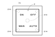
- FIG. 18 is a plan view of a switch device 1b according to a third embodiment of the present invention
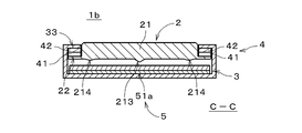
- FIG. 19 is a cross-sectional view of the switch device 1b at the position of arrow CC in FIG.
- the detection unit 5 includes a capacitive touch switch 51a similar to the switch device 1a of FIG.
- Other components are the same as those in FIG. 2, and the same components are denoted by the same reference numerals.
- an input projection 214 is provided in each of the left region and the right region of the projection 213 on the lower surface of the operation unit main body 21.
- the operation unit main body 21, the projection 213, and the input projection 214 are formed as one member with, for example, resin.
- the operation unit 2 when the operator pushes in the left area of the operation unit 2, the adsorption of the left magnetic member 42 and the magnetic member 41 is released. Then, with the projection 213 as a fulcrum, the operation unit 2 is inclined in a direction different from the above case, and the left input projection 214 comes into contact with the touch switch 51a. As a result, the pushing of the left portion of the operation unit 2 to the pushing position is detected by another detection element of the touch switch 51a.
- the detection unit 5 has a plurality of detection elements, and the protrusion 213 is provided on the lower surface of the operation unit 2. Then, when a part of the operation unit 2 is pushed in, the holding of the operation unit 2 by the position holding unit 4 is released, and the operation unit 2 is tilted with the protrusion 213 as a fulcrum, and the push-in is detected in the detection unit 5. It is detected by the detection element. In addition, when another part of the operation unit 2 is pushed in, the push-in is detected by another detection element of the detection unit 5 while the operation unit 2 is inclined in a different direction with the projection 213 as a fulcrum. The Thereby, the rocker switch of two notches can be realized in the switch device 1b that can easily change the push-in amount of the operation unit 2 using common components.
- one of the left magnetic member 41 and the right magnetic member 41 is attached to the first attachment position, and the other is attached to the second attachment position, so that the left region and the right side of the operation unit 2 are attached.
- the amount of push-in may differ depending on the area.
- the force required for pressing may be different between the left region and the right region of the operation unit 2.
- a tactile switch or the like may be provided at a position facing each input protrusion 214. In this case, each switch can be regarded as a detection element of the detection unit 5 (same as in the second embodiment).
- the switch device 1b three or more notches may be set.
- the T-shaped protrusion 213 is provided, thereby realizing the three-notch switch device 1b.
- the cross-shaped protrusion 213 is provided.
- a switch device 1b having four notches is realized.
- the switch device 1b that prevents the pressing of the operation unit 2 from being simultaneously detected in the plurality of detection elements of the touch switch 51a by providing the protrusion 213 can be realized in various modes.
- the protrusion may be provided at a position facing the lower surface of the operation unit 2 (for example, a position on the touch switch 51a).
- the switch devices 1, 1a, 1b can be variously modified.
- the plate-like magnetic member 42 and the small block-like magnetic member 41 are provided on the facing portion 33 and the operation end portion 22, respectively, but the surface on which the concave portion 420 is formed faces upward.
- the magnetic member 42 may be fixed to the operation end 22 and the magnetic member 41 may be attached to the lower surface of the facing portion 33.
- FIGS. 23 and 24 by shifting the position of the plate-like magnetic member 42, that is, by attaching the magnetic member 42 to different attachment positions, the gap width (pushing amount) between the magnetic members 42 and 41 is increased. ) May be changed. Also in these switch devices, it is possible to easily change the push-in amount of the operation unit 2 while using common parts by changing the attachment position to which the magnetic member is attached.
- a plurality of recesses 220 are formed on the upper surface of the operation end 22, and the magnetic member 41 is attached to the recess 220 on the upper surface, or Alternatively, it may be selectively attached to an attachment position outside the recess 220.
- the plate-like magnetic member 42 from which the concave portion 420 is omitted is provided in the facing portion 33.
- a plurality of recesses may be formed on the lower surface of the facing portion 33, and the magnetic member 41 may be selectively attached to an attachment position inside the recess on the lower surface or an attachment position outside the recess. In this case, the plate-like magnetic member 42 from which the concave portion 420 is omitted is provided on the operation end portion 22.
- the position holding unit 4 includes the first magnetic member provided in one portion of the facing portion 33 and the operation end portion 22 and the other of the facing portion 33 and the operation end portion 22. And a second magnetic member that is provided opposite to the first magnetic member and holds the operating portion 2 in a steady position by a magnetic attractive force generated between the first magnetic member and the first magnetic member.
- part has the some attachment position which a 1st magnetic member can attach, and between the 1st magnetic member and the 2nd magnetic member at the time of the operation part 2 being pushed into the pushing position
- the switch device by changing the attachment position where the first magnetic member is attached, it is possible to easily change the pushing amount of the operation unit 2 while using common parts.
- the push-in amount may be different in three or more stages.
- the magnetic member 41 and the magnetic member 42 form a part of the facing portion 33. It may be adsorbed through.
- the pushing amount of the operation unit 2 is the width of the gap where no member exists between the magnetic member 41 and the magnetic member 42 when the operation unit 2 is pushed into the pushing position.
- the touch switch 51 a is used for the detection unit 5, and a plurality of inputs are provided on the outer edge of the lower surface of the operation unit main body 21. Protrusion 211 may be provided. As a result, as shown in FIG. 28, even when a part of the outer edge of the large operation unit 2 is pushed in by the operator, the switch device 1 can appropriately detect the pushing of the operation unit 2. .
- the operation unit 2 is supported by the support structure 3 so that the other operation line-shaped portion 221 can move (turn) with the one operation line-shaped portion 221 as a fulcrum. Also good. That is, the operation unit 2 may be pushed in by rotating the operation unit 2 with the one operation linear portion 221 as a fulcrum. In this case, the magnetic members 41 and 42 in the one operation linear portion 221 are omitted.
- a fixed unit 91 to which a plurality of switch devices 1 can be fixed is prepared, and the switch unit 9 is configured by attaching the plurality of switch devices 1 to each fixed frame 911 of the fixed unit 91.
- the side surface portion 31 of the support structure 3 is provided with a protruding portion 311 protruding outward, and the protruding portion 311 engages with a recess 912 formed in the fixed frame 911, so that the switch device 1 is fixed to the fixed frame. It is fixed to 911.
- a dedicated circuit board 92 is provided inside the fixed unit 91, and a contactor 93 connected to the detection unit 5 is provided on the lower surface of the bottom surface portion 32 of the support structure 3 in each switch device 1.
- a current is supplied to the detection unit 5 through the circuit board 92 and the contact 93. Further, the circuit board 92 is provided with a communication module or the like. As a result, communication between the switch unit 9 and an external device such as a lighting device is performed, and operations such as dimming can be performed.
- the operation unit 2 is formed of a light-transmitting material (for example, a translucent material), and a light emitting element such as an LED is provided below the operation unit 2.
- the light emitting element may be turned on / off according to the position of the operation unit 2.
- the operation unit 2 and the detection unit 5 are formed of a transparent material, and a display device such as a liquid crystal display or an EL (Electroluminescence) display is provided below the detection unit 5. Also good. As a result, a display function can be added to the switch devices 1, 1a, 1b.
Landscapes
- Push-Button Switches (AREA)
- Switches With Compound Operations (AREA)
- Tumbler Switches (AREA)
Abstract
La présente invention concerne un dispositif de commutation (1) comprenant une structure de support (3), une unité de maintien en position (4), et une unité de détection (5). La structure de support (3) supporte une unité d'actionnement (2) de façon qu'elle puisse se déplacer dans la direction verticale. L'unité de maintien en position (4) supporte l'unité d'actionnement (2) en position d'équilibre. L'unité de détection (5) détecte que l'unité d'actionnement (2) est emmanchée à force dans une position d'emmanchement à force. Une section opposée (33) de la structure de support (3) est prévue sur une section d'extrémité d'actionnement (22) qui est une section d'extrémité latérale de l'unité d'actionnement (2). Un élément magnétique de forme plate (42) est prévu dans la section opposée (33). Des régions de côté inférieur et de côté supérieur (421, 422) sont formées sur une surface inférieure de l'élément magnétique, les régions de côté inférieur et de côté supérieur (421, 422) ayant des hauteurs différentes. La section d'extrémité d'actionnement (22) comprend des première et deuxième positions de fixation auxquelles l'élément magnétique (41) peut être fixé. Les première et deuxième positions de fixation font respectivement face aux régions de côté inférieur et de côté supérieur (421, 422). La quantité d'emmanchement à force est ainsi telle qu'elle diffère en fonction de la position de fixation de l'élément magnétique (42), la quantité d'emmanchement à force étant la largeur de vide entre les éléments magnétiques lorsque l'unité d'actionnement (2) est positionnée à la position d'emmanchement à force. En conséquence, il devient possible de changer aisément la quantité d'emmanchement à force de l'unité d'actionnement (2) à l'aide d'un composant commun.
Applications Claiming Priority (2)
| Application Number | Priority Date | Filing Date | Title |
|---|---|---|---|
| JP2013-085642 | 2013-04-16 | ||
| JP2013085642A JP5775542B2 (ja) | 2013-04-16 | 2013-04-16 | スイッチ装置 |
Publications (1)
| Publication Number | Publication Date |
|---|---|
| WO2014171408A1 true WO2014171408A1 (fr) | 2014-10-23 |
Family
ID=51731349
Family Applications (1)
| Application Number | Title | Priority Date | Filing Date |
|---|---|---|---|
| PCT/JP2014/060504 Ceased WO2014171408A1 (fr) | 2013-04-16 | 2014-04-11 | Dispositif de commutation |
Country Status (2)
| Country | Link |
|---|---|
| JP (1) | JP5775542B2 (fr) |
| WO (1) | WO2014171408A1 (fr) |
Cited By (1)
| Publication number | Priority date | Publication date | Assignee | Title |
|---|---|---|---|---|
| GB2577041A (en) * | 2018-09-06 | 2020-03-18 | Gamesman Ltd | Button assembly |
Families Citing this family (1)
| Publication number | Priority date | Publication date | Assignee | Title |
|---|---|---|---|---|
| JP7323386B2 (ja) * | 2019-08-28 | 2023-08-08 | 株式会社ジャパンディスプレイ | 操作支援装置 |
Citations (6)
| Publication number | Priority date | Publication date | Assignee | Title |
|---|---|---|---|---|
| JPS6279329U (fr) * | 1985-11-07 | 1987-05-21 | ||
| JPH01145025U (fr) * | 1988-03-30 | 1989-10-05 | ||
| JPH09265873A (ja) * | 1996-03-28 | 1997-10-07 | Idec Izumi Corp | 薄型スイッチおよびスイッチ付表示パネル |
| JP2006294271A (ja) * | 2005-04-05 | 2006-10-26 | Hosiden Corp | 多方向入力装置 |
| JP2010250971A (ja) * | 2009-04-10 | 2010-11-04 | Citizen Electronics Co Ltd | 表示装置 |
| JP2012022793A (ja) * | 2010-07-12 | 2012-02-02 | Citizen Electronics Co Ltd | シートスイッチ及び入力装置 |
-
2013
- 2013-04-16 JP JP2013085642A patent/JP5775542B2/ja not_active Expired - Fee Related
-
2014
- 2014-04-11 WO PCT/JP2014/060504 patent/WO2014171408A1/fr not_active Ceased
Patent Citations (6)
| Publication number | Priority date | Publication date | Assignee | Title |
|---|---|---|---|---|
| JPS6279329U (fr) * | 1985-11-07 | 1987-05-21 | ||
| JPH01145025U (fr) * | 1988-03-30 | 1989-10-05 | ||
| JPH09265873A (ja) * | 1996-03-28 | 1997-10-07 | Idec Izumi Corp | 薄型スイッチおよびスイッチ付表示パネル |
| JP2006294271A (ja) * | 2005-04-05 | 2006-10-26 | Hosiden Corp | 多方向入力装置 |
| JP2010250971A (ja) * | 2009-04-10 | 2010-11-04 | Citizen Electronics Co Ltd | 表示装置 |
| JP2012022793A (ja) * | 2010-07-12 | 2012-02-02 | Citizen Electronics Co Ltd | シートスイッチ及び入力装置 |
Cited By (1)
| Publication number | Priority date | Publication date | Assignee | Title |
|---|---|---|---|---|
| GB2577041A (en) * | 2018-09-06 | 2020-03-18 | Gamesman Ltd | Button assembly |
Also Published As
| Publication number | Publication date |
|---|---|
| JP2014207207A (ja) | 2014-10-30 |
| JP5775542B2 (ja) | 2015-09-09 |
Similar Documents
| Publication | Publication Date | Title |
|---|---|---|
| US8912458B2 (en) | Touchsurface with level and planar translational travel responsiveness | |
| US20200019263A1 (en) | Capacitive motor vehicle operating system | |
| TWI459425B (zh) | 發光鍵盤 | |
| US8173922B2 (en) | Thin type illuminated keyboard | |
| US6670873B2 (en) | Thin switch and display panel provided with switch | |
| JP2020514875A (ja) | 自動車用の操作装置 | |
| KR970701419A (ko) | 박형 스위치 장치 및 스위치 부설 표시장치(thin switch device and display with switch) | |
| TW201421511A (zh) | 發光鍵盤 | |
| US20140151204A1 (en) | Keyswitch | |
| JP2011030226A (ja) | センサ素子装置 | |
| TW201426803A (zh) | 發光鍵盤 | |
| TWI553682B (zh) | 發光鍵盤 | |
| US20110220477A1 (en) | Keypad structure | |
| JP4888202B2 (ja) | 入力操作部品 | |
| JP5775542B2 (ja) | スイッチ装置 | |
| TWI571900B (zh) | 發光鍵盤 | |
| EP3570143A1 (fr) | Générateur de force réactive et afficheur monté sur véhicule comprenant un générateur de force réactive | |
| CN102484011B (zh) | 作为汽车中的统一操作板的按键开关组 | |
| CN103094001A (zh) | 按键 | |
| JP5027061B2 (ja) | スイッチ装置 | |
| TWI578353B (zh) | 磁吸按鍵及其磁吸按鍵製造方法 | |
| JP2015227016A (ja) | 加飾成形品、照光式スイッチ、及び電子機器 | |
| EP3104388B1 (fr) | Dispositif d'entree | |
| TWI523056B (zh) | 按鍵 | |
| JP2008243655A (ja) | 可動接点体およびそれを用いて構成した照光式パネルスイッチ |
Legal Events
| Date | Code | Title | Description |
|---|---|---|---|
| 121 | Ep: the epo has been informed by wipo that ep was designated in this application |
Ref document number: 14785454 Country of ref document: EP Kind code of ref document: A1 |
|
| NENP | Non-entry into the national phase |
Ref country code: DE |
|
| 122 | Ep: pct application non-entry in european phase |
Ref document number: 14785454 Country of ref document: EP Kind code of ref document: A1 |