WO2014174607A1 - Centre de données de type conteneur pourvu d'un appareil de conditionnement d'air - Google Patents
Centre de données de type conteneur pourvu d'un appareil de conditionnement d'air Download PDFInfo
- Publication number
- WO2014174607A1 WO2014174607A1 PCT/JP2013/062045 JP2013062045W WO2014174607A1 WO 2014174607 A1 WO2014174607 A1 WO 2014174607A1 JP 2013062045 W JP2013062045 W JP 2013062045W WO 2014174607 A1 WO2014174607 A1 WO 2014174607A1
- Authority
- WO
- WIPO (PCT)
- Prior art keywords
- container
- air
- area
- cooling
- data center
- Prior art date
- Legal status (The legal status is an assumption and is not a legal conclusion. Google has not performed a legal analysis and makes no representation as to the accuracy of the status listed.)
- Ceased
Links
Images



Classifications
-
- H—ELECTRICITY
- H05—ELECTRIC TECHNIQUES NOT OTHERWISE PROVIDED FOR
- H05K—PRINTED CIRCUITS; CASINGS OR CONSTRUCTIONAL DETAILS OF ELECTRIC APPARATUS; MANUFACTURE OF ASSEMBLAGES OF ELECTRICAL COMPONENTS
- H05K7/00—Constructional details common to different types of electric apparatus
- H05K7/20—Modifications to facilitate cooling, ventilating, or heating
- H05K7/20709—Modifications to facilitate cooling, ventilating, or heating for server racks or cabinets; for data centers, e.g. 19-inch computer racks
- H05K7/20718—Forced ventilation of a gaseous coolant
- H05K7/20745—Forced ventilation of a gaseous coolant within rooms for removing heat from cabinets, e.g. by air conditioning device
-
- G—PHYSICS
- G06—COMPUTING OR CALCULATING; COUNTING
- G06F—ELECTRIC DIGITAL DATA PROCESSING
- G06F1/00—Details not covered by groups G06F3/00 - G06F13/00 and G06F21/00
- G06F1/16—Constructional details or arrangements
- G06F1/20—Cooling means
Definitions
- the present invention relates to a container-type data center equipped with air conditioning equipment, and more particularly, to a container-type data center equipped with air-conditioning equipment that can easily improve the cooling efficiency of IT equipment and the like when applied to existing containers. About.
- a container-type data center is a container-type box used as a freight transportation means such as a trailer and accommodates facilities necessary for configuring a data center. is there.
- the container itself can operate as a data center by accommodating servers, storage, control equipment, air conditioning facilities, power supply facilities, and the like in the container type data center. Therefore, it can be said that it is a form of a new data center that can be installed outdoors or transported.
- Patent Document 1 Japanese Patent Application Laid-Open No. 2012-98799 has an object to provide a rational unit-type data center and a server room unit that is effective as a component of the unit-type data center.
- the server room unit includes a plurality of server racks and cooling equipment in casings that can be arranged adjacent to each other, and functions as a server room.
- a cold area and a hot area are partitioned in the casing, and the server rack can be ventilated to be arranged in a line at the boundary between the cold area and the hot area.
- a cooling system configured by an exhaust fan configured to supply outside air to a cold area and exhaust the outside from a hot area, and an air conditioner configured to circulate the inside of the casing by preparing cold air.
- Patent Document 2 Japanese Patent Application Laid-Open No. 2012-252539 discloses a building containing an electronic device that efficiently releases indoor heat to the outside while improving airtightness and protecting the electronic device. It is an issue to make it easier to add or relocate.
- Fasteners that can be fastened by fasteners are fixed to the upper and lower parts of the columnar members arranged at the four corners of the building, and the roof of the building is set at a lower position than the fasteners.
- the heat generated from the electronic device is radiated to the outside air by the heat exchanger in the lower room and the outdoor heat exchanger.
- the interior of the building is divided into a computer room CR in which computers such as servers and storages are housed, and a machine room MR in which a power supply unit EU for supplying power to the computers and the like, an outdoor unit CD for preliminary air conditioning, and the like are installed. A partition wall is installed between them.
- Patent Document 2 it is necessary to divide the container into two compartments, and a server rack must be provided at the boundary between the compartments. To renovate an existing container such as a container for offices, a great amount of renovation costs are incurred.
- a container-type data center that can easily divide the inside of the container into a cooling area and a heat exhaust area simply by applying it to an existing container and enhance the cooling effect of the IT equipment stored in the rack.
- the purpose is to provide air conditioning equipment.
- a container-type data center equipped with an air conditioner according to the present invention includes a plurality of racks for storing a plurality of IT devices, and includes an indoor unit and an outdoor unit as air conditioners for cooling the IT devices.
- a container-type data center based on a container standard for transportation, wherein the container-type data center includes an indoor area in which the IT equipment and the indoor unit of the air conditioning equipment are arranged by a partition plate, and an outdoor unit of the air conditioning equipment The indoor unit installed in the indoor area in which the IT equipment is disposed is blown into the top portion of the indoor unit and the blower port for sending the cooling air upward, and sucks warm air from the lower part.
- a plurality of racks each having an inlet and the IT device arranged in the indoor area are cooled to one side with the racks arranged as a boundary.
- a rear heat exhaust area is formed on the other side, and the air blown above the indoor unit installed in the indoor area is guided to the cooling area in order to guide the cool air blown out from the blower outlet above the indoor unit installed in the indoor area.
- the system ceiling is arranged according to the height of the mouth.
- the system ceiling is formed in a trapezoidal cross section, and the dimension in the width direction on the indoor unit side is wider than the dimension in the width direction of the blower opening,
- the width on the cooling area side is a width corresponding to the distance from the container center to the container side wall, and a down wall is provided on the hypotenuse.
- the container-type data center equipped with the air-conditioning equipment has the top of the rack and the ceiling of the container so that the cooling air does not flow through the rack in which the IT equipment is mounted without flowing from the cooling area to the exhaust heat area.
- a cooling air outflow prevention member is formed in a gap with the surface.
- the container-type data center equipped with the air-conditioning equipment has a passage of personnel to the cooling area so that the cooling air does not flow through the rack equipped with the IT equipment and does not flow out from the cooling area to the exhaust heat area.
- a warm air-like cooling air outflow prevention member is installed at a certain location.
- the inside of a container is divided into a cooling area and an exhaust heat area by a rack, and cooling air is supplied to the exhaust heat area before passing through the rack by an air passage formed by the system ceiling / down wall and the container ceiling surface. Since it does not flow out, the cooling area has the function of a duct, and cooling air can be reliably sent to the rack containing the IT equipment without providing a duct, and the structure for improving the cooling efficiency is low. It can be realized at a cost.
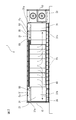
- FIG. 1 is a plan view showing the arrangement relationship of devices in a container, showing a container type data center equipped with the air conditioning equipment of the present invention.
- FIG. 2 is a cross-sectional view of the container type data center along the line AA shown in FIG.
- FIG. 3 is a cross-sectional view of the container type data center taken along line BB shown in FIG.
- FIG. 4 is a cross-sectional view of the container type data center taken along the line CC shown in FIG.
- FIG. 5 is a detailed view of the system ceiling used in a container-type data center equipped with the air conditioning equipment of the present invention.
- FIG. 6 is a detailed view showing another example of the system ceiling used in the container-type data center equipped with the air conditioning equipment of the present invention.
- the longitudinal direction of the container is expressed as “length direction”, and the direction perpendicular thereto is expressed as “width direction”.
- the expressions “inside” and “outside” refer to the direction toward the inside of the container as “inward” and the direction toward the outside as “outward” or “outside”.
- Non-Patent Document 1 The applicant has also developed a container type data center as described in Non-Patent Document 1.
- IT equipment such as servers and power / air-conditioning equipment are accommodated in containers, and necessary equipment in the data center is condensed. Since the outside is sized for transportation, transportation to various locations is possible.
- the interior has a layout that ensures a sufficient maintenance space.
- the container-type data center developed by the applicant can be automated by implementing a remote operation monitoring service. Moreover, the status of air conditioning, power, and power supply can be confirmed, and the server in the container can be visually confirmed remotely by a monitoring camera. Therefore, it is possible to quickly detect and take measures against the occurrence of a failure. Furthermore, it is configured to be able to detect abnormalities such as unauthorized intrusion into a container by external monitoring by a monitoring camera, surrounding security by a laser, and entrance / exit management by biometric authentication.
- the container 1 is a container having a structure conforming to the ISO standard.
- the container size and the upper / lower contact interface have a structure conforming to the ISO container standard (ISO standard 6346).
- the container 1 is formed of two sets of substantially rectangular shapes made of iron H-steel, each of which is formed as an upper frame and a lower frame (not shown), and their four corners are connected by pillars 10 that are also made of iron H-steel.
- a shaft is formed and formed into a substantially rectangular parallelepiped shape.
- An iron plate is attached to the upper frame to form a ceiling surface 25, and similarly, an iron plate is attached to the lower frame to form a floor surface 26.
- twist lock mechanisms are formed at the four corners of the upper frame and the lower frame of the container 1 to serve as a positioning guide when stacking a plurality of containers 1 and to prevent displacement of the stacked containers. It also serves as.
- the container type data center of the present invention is a sealed steel container and the door is air tight. Internal heat generated from IT equipment is cooled by an air conditioner installed inside, and an air circulation system is adopted. As a result, it is possible to ensure high waterproof / dustproof performance by operating unattended during operation. However, it is necessary to consider the ventilation when working in the container.
- the external shape can be designed freely according to the number of racks in which IT equipment is installed, but the example is the same size as the 40ft container, and it is configured to have a fixed interface part for transportation by ship or trailer. To do. As a result, it is easy to fix in ship transportation, and in trailer transportation, there is an advantage that it can be transported with a standard trailer. However, since the product is delivered as a product when shipped on a ship, it is necessary to consider the transportation so as not to damage the container body.
- an anti-vibration table unit with an anti-vibration mechanism is installed at the bottom of the container so that trailer transportation with IT equipment can be carried. With this mechanism, the vertical vibration acceleration during transportation can be greatly reduced.
- the outdoor unit for container air conditioning can be configured to be installed on the same floor as the container, although it is outside the container in which the IT equipment is arranged, in order to improve mobility. .
- the refrigerant pipe can be fixed, and it is not necessary to re-install the outdoor unit and lay the refrigerant pipe every time it is moved.
- air-conditioning equipment four air-cooling units are installed, and one unit is reserved.
- Two indoor units 31 that are one of air conditioning facilities are installed at both ends in the longitudinal direction of the indoor area of the container 1.
- the indoor unit 31 sucks indoor air from the lower intake port 31b (FIG. 2), performs heat exchange in the outdoor unit 32, cools the sucked air, and passes through the blower port 31a above the indoor unit 31. Deliver cooled air.
- the container 1 is divided into an IT equipment storage room for storing a rack 40 in which IT equipment is stored by a partition plate 24 and an outdoor unit installation room for air conditioning equipment.
- the partitioning column part 10 is provided at the end in the width direction of the partition plate 24 by the same H steel as the column part 10.
- An iron door 13 is provided on the wall surface of the container 1 facing the outdoor unit installation room.
- the IT equipment storage chamber of the container 1 is equipped with iron plates on the ceiling surface, floor surface, and side surfaces in the portion surrounded by the upper frame, the lower frame, the pillar portion, and the partition pillar portion, A closed space is formed by the partition plate 24 and the iron door 13 arranged on the end face.
- the IT equipment storage room is air-conditioned and closed during operation, but an operator needs to enter and exit the IT equipment storage room during maintenance, etc.
- the entrance / exit 80 is appropriately formed.
- the iron door 13 on the wall surface facing the outdoor unit installation room of the container 1 serves as an entrance when the indoor unit 31 of the air conditioning equipment, the rack 40, and the IT equipment stored in the rack are carried in, and when the carry-in is completed Keep it closed.
- a predetermined number of racks 40 for storing IT devices are arranged in the center in the longitudinal direction of the container 1.
- the rack 40 is preferably one having a large gap such as a steel rack made of a plurality of stages of net shelves.
- the container 1 has a cooling area 2 in which cooling air cooled by the air conditioning equipment is discharged with the row of racks 40 on which IT equipment is placed as a boundary, and the cooling air passes through the rack 40 to cool the IT equipment. It is divided into an exhaust heat area 3 into which air containing exhaust heat flows.
- a vinyl curtain 60 is attached along the longitudinal direction in a gap formed between the top of the rack 40 and the ceiling surface 25 of the container 1 (FIG. 2). This prevents air from convection between the cooling area 2 and the exhaust heat area 3 in the upper part of the rack 40.
- the container 1 it is necessary to reliably send the cooling air sent from the indoor unit 31 to the cooling area 2.
- the ceiling 50 is used.
- the system ceiling 50 is formed of a plate-like member, and is suspended from the ceiling surface 25 of the container 1 by a hanger (not shown).
- the system ceiling 50 is positioned so that its height is substantially the same as that of the cooling air blowing port 31 a of the indoor unit 31.
- the system ceiling 50 has a trapezoidal shape in plan view, and it is required that the dimension in the width direction on the indoor unit 31 side be at least wider than the dimension in the width direction of the air blowing port 31a.
- the width of the area 2 side end is preferably a width dimension corresponding to the distance from the position of the vinyl curtain 60 provided in the longitudinal direction on the rack 40 to the side wall 22 of the container 1.
- the cold air from the blower port 31a is reliably introduced on the wide indoor unit 31 side, and is sent out toward the cooling area 2.
- a down wall 51 is provided between the system ceiling 50 and the ceiling surface 25 of the container 1, so that the cold air from the blower port 31 a at the top of the indoor unit 31 is exhausted from the exhaust heat area 3 side.
- a cylindrical air passage is formed from the air outlet 31 a at the top of the indoor unit 31 toward the cooling area 2, and the cooling area 2 itself has the same function as a duct.
- the shape of the system ceiling 50 is formed so that the down wall 51 is substantially U-shaped when viewed from the side, so that there is a gap between the horizontal portion of the system ceiling 50 and the inside of the side wall 22 of the container. In this way, the cooling air can be sent to the cooling area 2 more reliably.
- the cooling ceiling 2 can be provided with a duct function by the above-described system ceiling 50. However, if a space is provided under the system ceiling 50 to allow movement of personnel between the exhaust heat area 3 and the cooling area 2, Depending on the space, the air can be transferred between the cooling area 2 and the exhaust heat area 3. Below the system ceiling 50, there is an air inlet 31b of the indoor unit 31, and when warm air is sucked from here, there is a possibility that the cooling air flows directly toward the inlet 31b of the indoor unit 31 through this space. is there.
- a vinyl curtain 70 having approximately the same length as the length from the floor surface 26 of the container 1 to the height of the system ceiling 50 is provided at the end of the system ceiling 50 on the cooling area 2 side. Install and close. At this time, by setting the lower end and the left and right ends of the vinyl curtain 70 as free ends, it becomes warm, and it is possible to prevent air traffic and prevent convection of air.
- the cooling air sent from the blower port 31a of the indoor unit 31 is routed through the cooling area 2 along the path indicated by the arrow Fc (shown by a solid line).
- the cooling air can be reliably sent out toward the IT equipment mounted on the rack, and the air including the exhaust heat can be guided along the path indicated by the arrow Fh (indicated by a dotted line). It becomes possible to guide to the inlet 31b of the indoor unit 31.
- this structure can also prevent the air containing exhaust heat from flowing into the cooling area 2, it is possible to improve the cooling efficiency.
- the Example of this invention was explained in full detail, this invention is not limited to the said Example, A various deformation
- the vinyl curtain is suspended from the upper portion of the rack 40.
- the present invention is not limited to this, and the gap at the upper portion of the rack 40 may be closed by a plate-like member. There is no problem in any form as long as the structure can prevent the inflow of air.
Landscapes
- Engineering & Computer Science (AREA)
- Physics & Mathematics (AREA)
- General Engineering & Computer Science (AREA)
- Theoretical Computer Science (AREA)
- Computer Hardware Design (AREA)
- Thermal Sciences (AREA)
- Microelectronics & Electronic Packaging (AREA)
- Human Computer Interaction (AREA)
- General Physics & Mathematics (AREA)
- Cooling Or The Like Of Electrical Apparatus (AREA)
Abstract
Priority Applications (3)
| Application Number | Priority Date | Filing Date | Title |
|---|---|---|---|
| US14/782,028 US9345174B2 (en) | 2013-04-24 | 2013-04-24 | Container-type data center having air conditioning facility |
| JP2014543379A JP5723492B2 (ja) | 2013-04-24 | 2013-04-24 | 空調設備を備えたコンテナ型データセンター |
| PCT/JP2013/062045 WO2014174607A1 (fr) | 2013-04-24 | 2013-04-24 | Centre de données de type conteneur pourvu d'un appareil de conditionnement d'air |
Applications Claiming Priority (1)
| Application Number | Priority Date | Filing Date | Title |
|---|---|---|---|
| PCT/JP2013/062045 WO2014174607A1 (fr) | 2013-04-24 | 2013-04-24 | Centre de données de type conteneur pourvu d'un appareil de conditionnement d'air |
Publications (1)
| Publication Number | Publication Date |
|---|---|
| WO2014174607A1 true WO2014174607A1 (fr) | 2014-10-30 |
Family
ID=51791217
Family Applications (1)
| Application Number | Title | Priority Date | Filing Date |
|---|---|---|---|
| PCT/JP2013/062045 Ceased WO2014174607A1 (fr) | 2013-04-24 | 2013-04-24 | Centre de données de type conteneur pourvu d'un appareil de conditionnement d'air |
Country Status (3)
| Country | Link |
|---|---|
| US (1) | US9345174B2 (fr) |
| JP (1) | JP5723492B2 (fr) |
| WO (1) | WO2014174607A1 (fr) |
Cited By (4)
| Publication number | Priority date | Publication date | Assignee | Title |
|---|---|---|---|---|
| CN109152268A (zh) * | 2018-10-16 | 2019-01-04 | 郑州云海信息技术有限公司 | 一种高低密度服务器集装箱数据中心 |
| CN109195368A (zh) * | 2018-10-17 | 2019-01-11 | 郑州云海信息技术有限公司 | 一种多区域集装箱数据中心 |
| CN109496112A (zh) * | 2018-12-21 | 2019-03-19 | 郑州云海信息技术有限公司 | 一种集群式集装箱数据中心 |
| CN112930073A (zh) * | 2019-12-05 | 2021-06-08 | 北京京东尚科信息技术有限公司 | 用于数据中心的换热系统 |
Families Citing this family (14)
| Publication number | Priority date | Publication date | Assignee | Title |
|---|---|---|---|---|
| JP5762645B2 (ja) * | 2013-04-24 | 2015-08-12 | 株式会社日立システムズ | コンテナ型データセンター |
| KR101548328B1 (ko) * | 2014-04-23 | 2015-08-28 | 네이버비즈니스플랫폼 주식회사 | 서버실 냉각 장치 및 이를 구비하는 데이터 센터의 공조 시스템의 제조 방법 |
| CN106051999A (zh) * | 2016-06-08 | 2016-10-26 | 珠海格力电器股份有限公司 | 排风罩、风冷室外机组的安装结构 |
| CN107663954A (zh) * | 2016-07-28 | 2018-02-06 | 苏州安瑞可机柜系统有限公司 | 一种模块化服务器机房 |
| CN107703259A (zh) * | 2017-09-21 | 2018-02-16 | 浙江富春江环保科技研究有限公司 | 一种车载式可移动在线检测间 |
| US11606877B2 (en) * | 2018-11-08 | 2023-03-14 | Switch, Ltd. | Air transportable modular shipping container for edge data centers |
| CN109328007A (zh) * | 2018-11-22 | 2019-02-12 | 郑州云海信息技术有限公司 | 一种自然冷源集装箱数据中心 |
| US11340571B2 (en) * | 2020-02-11 | 2022-05-24 | Dell Products L.P. | System with retrofit enhancement of an ultra dense thermally challenged server |
| EP4252500A1 (fr) | 2020-11-25 | 2023-10-04 | Digital Porpoise, LLC | Système de refroidissement pour centre de données comprenant une technologie de refroidissement par décalage |
| CN112922393A (zh) * | 2021-01-21 | 2021-06-08 | 金茂智慧交通科技(天津)有限公司 | 一种基于集装箱改制的换电控制系统 |
| CN113179616A (zh) * | 2021-04-27 | 2021-07-27 | 山东英信计算机技术有限公司 | 一种多模块集装箱数据中心 |
| CN113757846B (zh) * | 2021-08-24 | 2023-06-16 | 华为数字能源技术有限公司 | 复合制冷系统和数据中心 |
| WO2024222227A1 (fr) * | 2023-04-28 | 2024-10-31 | 北京嘉楠捷思信息技术有限公司 | Récipient défini et dispositif de serveur de récipient défini |
| WO2024222230A1 (fr) * | 2023-04-28 | 2024-10-31 | 北京嘉楠捷思信息技术有限公司 | Conteneur séparé et dispositif serveur conteneurisé séparément |
Citations (3)
| Publication number | Priority date | Publication date | Assignee | Title |
|---|---|---|---|---|
| US20060082263A1 (en) * | 2004-10-15 | 2006-04-20 | American Power Conversion Corporation | Mobile data center |
| JP2010071482A (ja) * | 2008-09-16 | 2010-04-02 | Takasago Thermal Eng Co Ltd | 高密度熱負荷室用空調システム |
| JP2012053747A (ja) * | 2010-09-02 | 2012-03-15 | Ntt Facilities Inc | コンテナ型データセンター |
Family Cites Families (12)
| Publication number | Priority date | Publication date | Assignee | Title |
|---|---|---|---|---|
| WO2009137215A2 (fr) * | 2008-05-05 | 2009-11-12 | Carrier Corporation | Conteneur d'équipement informatique et unité de refroidissement intégrés |
| US7852627B2 (en) * | 2008-10-31 | 2010-12-14 | Dell Products L.P. | System and method for high density information handling system enclosure |
| JP5493608B2 (ja) * | 2009-09-07 | 2014-05-14 | 株式会社リコー | 転写装置及び画像形成装置 |
| JP5682025B2 (ja) * | 2010-10-29 | 2015-03-11 | 清水建設株式会社 | サーバ室ユニットおよびユニット型データセンター |
| CN102063166A (zh) * | 2010-11-17 | 2011-05-18 | 华为技术有限公司 | 集装箱式数据中心 |
| TW201227229A (en) * | 2010-12-31 | 2012-07-01 | Hon Hai Prec Ind Co Ltd | Container data center |
| US8462496B2 (en) * | 2011-02-23 | 2013-06-11 | Dell Products L.P. | System and method for a modular fluid handling system with modes in a modular data center |
| CN202058079U (zh) | 2011-03-24 | 2011-11-30 | 艾默生网络能源有限公司 | 集装箱数据中心 |
| TW201247087A (en) * | 2011-05-04 | 2012-11-16 | Hon Hai Prec Ind Co Ltd | Container data center |
| JP5419926B2 (ja) | 2011-06-06 | 2014-02-19 | 日本フルハーフ株式会社 | 電子機器を納めた簡易形の建造物 |
| TWI466628B (zh) * | 2011-07-07 | 2014-12-21 | Hon Hai Prec Ind Co Ltd | 貨櫃型資料中心散熱系統 |
| JP2013134032A (ja) * | 2011-12-27 | 2013-07-08 | Dai-Dan Co Ltd | 機器冷却システムおよび機器冷却方法 |
-
2013
- 2013-04-24 WO PCT/JP2013/062045 patent/WO2014174607A1/fr not_active Ceased
- 2013-04-24 US US14/782,028 patent/US9345174B2/en active Active
- 2013-04-24 JP JP2014543379A patent/JP5723492B2/ja not_active Expired - Fee Related
Patent Citations (3)
| Publication number | Priority date | Publication date | Assignee | Title |
|---|---|---|---|---|
| US20060082263A1 (en) * | 2004-10-15 | 2006-04-20 | American Power Conversion Corporation | Mobile data center |
| JP2010071482A (ja) * | 2008-09-16 | 2010-04-02 | Takasago Thermal Eng Co Ltd | 高密度熱負荷室用空調システム |
| JP2012053747A (ja) * | 2010-09-02 | 2012-03-15 | Ntt Facilities Inc | コンテナ型データセンター |
Cited By (5)
| Publication number | Priority date | Publication date | Assignee | Title |
|---|---|---|---|---|
| CN109152268A (zh) * | 2018-10-16 | 2019-01-04 | 郑州云海信息技术有限公司 | 一种高低密度服务器集装箱数据中心 |
| CN109195368A (zh) * | 2018-10-17 | 2019-01-11 | 郑州云海信息技术有限公司 | 一种多区域集装箱数据中心 |
| CN109496112A (zh) * | 2018-12-21 | 2019-03-19 | 郑州云海信息技术有限公司 | 一种集群式集装箱数据中心 |
| CN112930073A (zh) * | 2019-12-05 | 2021-06-08 | 北京京东尚科信息技术有限公司 | 用于数据中心的换热系统 |
| CN112930073B (zh) * | 2019-12-05 | 2024-04-12 | 北京京东尚科信息技术有限公司 | 用于数据中心的换热系统 |
Also Published As
| Publication number | Publication date |
|---|---|
| JPWO2014174607A1 (ja) | 2017-02-23 |
| US20160057892A1 (en) | 2016-02-25 |
| US9345174B2 (en) | 2016-05-17 |
| JP5723492B2 (ja) | 2015-05-27 |
Similar Documents
| Publication | Publication Date | Title |
|---|---|---|
| JP5723492B2 (ja) | 空調設備を備えたコンテナ型データセンター | |
| JP5762646B2 (ja) | コンテナ型データセンター | |
| JP5762645B2 (ja) | コンテナ型データセンター | |
| US20130061624A1 (en) | Modular datacenter element and modular datacenter cooling element | |
| US20140359998A1 (en) | Modular datacenter element and modular datacenter cooling element | |
| US9605855B2 (en) | Air conditioning system using outside air | |
| JP6578011B2 (ja) | 電子筐体ラインおよび前記電子筐体ラインに接続される冷却機を備える電子筐体装置 | |
| CN102405452A (zh) | 用于服务器群冷却系统的冷排包封 | |
| JP2010054090A (ja) | 空調システム | |
| CN102455022A (zh) | 空气调节系统 | |
| JP6442138B2 (ja) | 発熱機器を収容した室の空調システム | |
| JP2012256122A (ja) | 電子機器収容装置 | |
| JP6180151B2 (ja) | 空調システム | |
| JP6525826B2 (ja) | データセンターの空調システム | |
| JP5419926B2 (ja) | 電子機器を納めた簡易形の建造物 | |
| JP2013210170A (ja) | 空調システム | |
| JP5912776B2 (ja) | 空調システム | |
| JP7621407B2 (ja) | クリーンルームの空調システム | |
| JP2012048548A (ja) | 機器収容ラック、及び該機器収容ラックを有するデータセンタ | |
| JPWO2014174608A1 (ja) | コンテナ型データセンター | |
| JP6117500B2 (ja) | 情報処理機器室の空調システム、及び縮流軽減装置 | |
| JP2011134803A (ja) | 電子機器収納ラック群の冷却装置及び方法 | |
| JP2012072999A (ja) | 情報処理関連機器用空調システム | |
| JP2014048814A (ja) | 冷却システム | |
| KR20190106537A (ko) | 실내 공기 배출 시스템 |
Legal Events
| Date | Code | Title | Description |
|---|---|---|---|
| ENP | Entry into the national phase |
Ref document number: 2014543379 Country of ref document: JP Kind code of ref document: A |
|
| 121 | Ep: the epo has been informed by wipo that ep was designated in this application |
Ref document number: 13882846 Country of ref document: EP Kind code of ref document: A1 |
|
| WWE | Wipo information: entry into national phase |
Ref document number: 14782028 Country of ref document: US |
|
| WWE | Wipo information: entry into national phase |
Ref document number: IDP00201506903 Country of ref document: ID |
|
| NENP | Non-entry into the national phase |
Ref country code: DE |
|
| 122 | Ep: pct application non-entry in european phase |
Ref document number: 13882846 Country of ref document: EP Kind code of ref document: A1 |