WO2014174631A1 - Appareil d'inspection de dispositif d'affichage et procédé d'inspection de dispositif d'affichage - Google Patents
Appareil d'inspection de dispositif d'affichage et procédé d'inspection de dispositif d'affichage Download PDFInfo
- Publication number
- WO2014174631A1 WO2014174631A1 PCT/JP2013/062208 JP2013062208W WO2014174631A1 WO 2014174631 A1 WO2014174631 A1 WO 2014174631A1 JP 2013062208 W JP2013062208 W JP 2013062208W WO 2014174631 A1 WO2014174631 A1 WO 2014174631A1
- Authority
- WO
- WIPO (PCT)
- Prior art keywords
- test video
- answer
- inspection
- unit
- visual recognition
- Prior art date
- Legal status (The legal status is an assumption and is not a legal conclusion. Google has not performed a legal analysis and makes no representation as to the accuracy of the status listed.)
- Ceased
Links
Images


Classifications
-
- H—ELECTRICITY
- H04—ELECTRIC COMMUNICATION TECHNIQUE
- H04N—PICTORIAL COMMUNICATION, e.g. TELEVISION
- H04N5/00—Details of television systems
- H04N5/66—Transforming electric information into light information
-
- G—PHYSICS
- G09—EDUCATION; CRYPTOGRAPHY; DISPLAY; ADVERTISING; SEALS
- G09G—ARRANGEMENTS OR CIRCUITS FOR CONTROL OF INDICATING DEVICES USING STATIC MEANS TO PRESENT VARIABLE INFORMATION
- G09G5/00—Control arrangements or circuits for visual indicators common to cathode-ray tube indicators and other visual indicators
-
- H—ELECTRICITY
- H04—ELECTRIC COMMUNICATION TECHNIQUE
- H04N—PICTORIAL COMMUNICATION, e.g. TELEVISION
- H04N17/00—Diagnosis, testing or measuring for television systems or their details
- H04N17/04—Diagnosis, testing or measuring for television systems or their details for receivers
-
- G—PHYSICS
- G09—EDUCATION; CRYPTOGRAPHY; DISPLAY; ADVERTISING; SEALS
- G09G—ARRANGEMENTS OR CIRCUITS FOR CONTROL OF INDICATING DEVICES USING STATIC MEANS TO PRESENT VARIABLE INFORMATION
- G09G2320/00—Control of display operating conditions
- G09G2320/06—Adjustment of display parameters
- G09G2320/0693—Calibration of display systems
-
- G—PHYSICS
- G09—EDUCATION; CRYPTOGRAPHY; DISPLAY; ADVERTISING; SEALS
- G09G—ARRANGEMENTS OR CIRCUITS FOR CONTROL OF INDICATING DEVICES USING STATIC MEANS TO PRESENT VARIABLE INFORMATION
- G09G2330/00—Aspects of power supply; Aspects of display protection and defect management
- G09G2330/12—Test circuits or failure detection circuits included in a display system, as permanent part thereof
-
- G—PHYSICS
- G09—EDUCATION; CRYPTOGRAPHY; DISPLAY; ADVERTISING; SEALS
- G09G—ARRANGEMENTS OR CIRCUITS FOR CONTROL OF INDICATING DEVICES USING STATIC MEANS TO PRESENT VARIABLE INFORMATION
- G09G2380/00—Specific applications
- G09G2380/08—Biomedical applications
Definitions
- the present invention relates to a display device inspection device and a display device inspection method for inspecting display quality of a display device.
- the display quality of a display device that displays medical images is inspected and managed by a method defined in each country.
- the display quality of display devices in Japan is managed according to guidelines established by JESRA (Japan Radiological Technology Society).
- JESRA Joint Radiological Technology Society
- Patent Document 1 As an apparatus for measuring the display quality of a display device, there is an apparatus shown in Patent Document 1. With this apparatus, contrast and gradation linearity can be measured. By using these measurement results, it is possible to grasp the display quality and obtain a predetermined quality.
- a test pattern image in which a plurality of rectangular figures with different gradations are arranged is displayed on the display screen, and this is visually checked for visibility.
- a method for inspecting the gradation characteristics For example, whether or not the gradation according to the test pattern image is correctly viewed is visually observed.
- Examples of the test pattern image displayed on this screen include an image in which a plurality of types of rectangular figures having different gradations are arranged as shown in FIG. In such a test pattern image, an inspection is performed by observing an area in which figures having a small difference in brightness are arranged in the vicinity, as indicated by symbol a.
- the present invention provides a test video generation unit that generates a test video including graphics with different gradations and an answer to the test video, a display unit that displays the test video, and a visual recognition result for the displayed test video. Based on an input unit to be input, an answer corresponding to the test video, and the visual recognition result, a determination unit that determines whether the answer and the visual recognition result match, and a determination result of the determination unit is stored And a storage unit that outputs the stored determination result.
- the present invention generates a test video including a graphic with different gradations and an answer to the test video, displays the test video on a display unit, inputs a visual recognition result for the displayed test video, Based on the answer corresponding to the test video and the visual recognition result, it is determined whether or not the answer and the visual recognition result match, the determination result obtained by the determination is stored, and the stored determination result Is output.
- the present invention provides a test video generation means for generating a test video including graphics having different gradations and an answer to the test video, and an input means for inputting a visual recognition result for the test video displayed on the display means.
- Determining means for determining whether or not the answer matches the visual recognition result based on the answer corresponding to the test video and the visual recognition result; and storage means for storing the determination result of the determination unit in a storage device ,
- An inspection program for a display device for functioning as output means for outputting the stored determination result.
- a test video and an answer to the test video are generated, a visual result of the displayed test video is input, and whether or not the answer matches the visual result is determined and stored. As a result, it is possible to grasp the certainty as to whether or not the gradation characteristics of the display device have been correctly inspected.
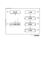
- FIG. 1 is a schematic block diagram showing the configuration of an inspection apparatus according to an embodiment of the present invention.
- the inspection apparatus 1 can be used for inspection of display quality of the display device.
- the test video generation unit 11 generates a test video including graphics with different gradations and an answer to the test video.
- the display unit 12 displays a test video.
- the input unit 13 inputs a visual recognition result for the displayed test video.
- the determination unit 14 determines whether the answer and the visual recognition result match based on the answer corresponding to the test video and the visual recognition result.
- the storage unit 15 stores the determination result.
- the output unit 16 outputs the stored determination result.
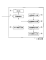
- FIG. 2 is a schematic block diagram showing the configuration of the display device 2 in the second embodiment.
- the display device 2 has the function of the inspection device described above.
- the test video generation unit 20 generates a test video including graphics with different gradations and an answer to the test video. More specifically, the test video generation unit 20 generates a test video that is an image including a graphic with a gradation different from the background and an answer corresponding to the shape of the graphic.
- a test video for example, an image including an annular figure partially opened can be used, and information indicating the opening direction of the figure can be used as an answer to the test video.
- the test video may be a graphic with a gradation different from that of the background. For example, characters and symbols can be used in addition to the circular graphic with a part opened. As an answer, information representing characters and symbols can be used.
- the image control unit 21 displays on the display unit 22 a video signal corresponding to the test video generated by the test video generation unit 20 or a video signal output from an external video output device (computer or the like). For example, the image control unit 21 displays the video signal output from the video output device in the normal mode, and according to the test video generated by the test video generation unit 20 in the inspection mode for inspecting the display quality of the display device 2. Display the video signal.
- Display unit 22 displays a test signal corresponding to the test video and a video signal output from the video output device.
- the display unit 22 is, for example, a liquid crystal panel or a plasma display panel.
- the inspection result input unit 23 inputs a visual confirmation result confirmed visually with respect to the displayed test video.
- the inspection result input unit 23 can input a visual result by operating a button provided on the display device 2 by an OSD (On-Screen Display) function, for example.
- the visual recognition result can also be input from an input device such as a keyboard or a numeric keypad connected via a computer.
- the inspection result determination unit 24 determines whether or not the answer matches the visual recognition result based on the answer corresponding to the test video and the visual recognition result. For example, the inspection result determination unit 24 determines whether or not the opening direction represented by the answer generated by the test video generation unit 20 matches the opening direction represented by the visual recognition result input from the inspection result input unit 23. . In addition, when the test video is a graphic representing a character, the test result determination unit 24 determines the answer that is the character represented by the test video generated by the test video generation unit 20 and the visual recognition result input from the test result input unit 23. Can be compared to determine whether they match.
- the inspection history storage unit 25 stores the inspection history.
- the inspection history storage unit 25 is a storage device such as a semiconductor memory or a hard disk.
- the inspection history is information in which the answer generated by the test video generation unit 20, the inspection result input from the inspection result input unit 23, and the determination result determined by the inspection result determination unit 24 are associated with each other.
- the inspection history can be included as a history for each of the plurality of test videos that have been inspected.
- the inspection history may further optionally include at least one of the date and time of the inspection, the inspector, and information on the test video displayed when the inspection was performed.
- the date and time when the inspection was performed can be obtained from a clock function in the display device 2.
- the inspector can obtain an inspector name, an ID for identifying the inspector, and the like through the input device when performing the inspection.
- the information relating to the test video may be the test video itself, or may be information indicating the brightness of each graphic included in the test video.
- the inspection history output unit 26 outputs the inspection history stored in the inspection history storage unit 25.
- the inspection history output unit 26 may be an output interface that outputs the inspection history read from the inspection history storage unit 25 to an externally connected computer. Moreover, you may make it output by displaying a determination result on the display part 22. FIG.
- FIG. 3 is a flowchart for explaining the operation of the display device 2.
- the display device 2 switches from the normal mode for displaying the video signal to the inspection mode.
- the test video generation unit 20 When switched to the inspection mode, the test video generation unit 20 generates a test video and an answer to the test video (step S11).
- FIG. 4 is a diagram illustrating an example of the generated test video.
- the test video is a figure in which a part (right side in this figure) of the ring is opened, for example, a Landolt ring.
- the brightness of the Landolt ring and the background can be arbitrarily set.
- the lightness of the Landolt ring and the lightness of the background are set and generated according to the gradation for which visibility is to be confirmed.
- the lightness of the background is 2%
- the lightness of the Landolt ring is 12%
- the background is darker than the Landolt ring.
- the direction of the opening of the Landolt ring can be randomly set and generated as a test video, and information on the set direction of the opening is generated as an answer together with the test video.
- the test video generation unit 20 outputs the generated test video to the image control unit 21, and outputs the generated answer to the test result determination unit 24.
- an E chart of a vision test symbol can be used as a figure other than the Landolt ring.
- other figures that can recognize the direction can be used, and characters can also be used.
- the image control unit 21 displays a video signal corresponding to the test video on the display unit 22 (step S12). On the display unit 22, the test video as shown in FIG. 4 is displayed.
- the inspection result input unit 23 inputs the result as the inspection result based on the pressed button (step S13).
- information indicating in which direction the opening of the Landolt ring appears to be present is input.
- an input is made by pressing a button representing up, down, left, or right of the buttons of the display device 2.
- the inspection result determination unit 24 compares the inspection result obtained from the inspection result input unit 23 with the answer obtained from the test video generation unit 20 to determine whether or not they match. Thus, it is determined whether or not the answer corresponding to the test video matches the visual recognition result (step S14). Then, the inspection result determination unit 24 stores the determination result in the inspection history storage unit 25 (step S15). For example, when the inspection result is “up” and the answer is “up”, the directions are matched, so that a determination result indicating matching is obtained. On the other hand, when the inspection result is “right” and the answer is “up”, the direction does not match, and therefore a determination result indicating that they do not match is obtained.
- the display device 2 determines whether or not the inspection is completed when determined by the inspection result determination unit 24 (step S16). If the inspection is not completed, the display device 2 proceeds to step S11. If the test is not completed, the test video generation unit 20 can generate the same test video and answer as the test video and answer performed immediately before, or a test different from the test video and answer performed immediately before. Images and answers can also be generated. In addition, the test video generation unit 20 can set the test video and the answer at random. That is, the test video generation unit 20 can randomly determine the opening direction of the Landolt ring to be generated as the test video, can determine the opening direction as an answer, and can randomly determine the graphic or character to be generated as the test video, An answer corresponding to the graphic or character can be generated.
- the inspection history output unit 26 is connected to the outside of the display device 2 via a computer, whether or not an instruction to output the inspection history is input from a button provided on the display device 2.
- an inspection history including the inspection result stored in the inspection history output unit 26 is output (step S17).
- the inspection history to be output is, for example, information in which the inspection result input in step S13, the answer generated in step S11, and the determination result determined in step S14 are associated with each other.
- the inspection history output unit 26 does not output the inspection history when the time during which the instruction to output the inspection history is not input continues for a certain period of time, or when the instruction not to output the inspection history is input. Then, the display device 2 ends the inspection and returns the process to the normal mode.
- the quality inspection of the display device can be easily performed, and the inspection / recording can be easily and reliably performed.
- the inspection history output unit 26 has described the case of outputting the inspection history when an instruction to output the inspection result is input immediately after the inspection is completed.
- the inspection history can also be output when an instruction is input to output the inspection result in.
- an inspection is performed by observing a screen on which a video in which a plurality of types of rectangular figures are arranged is displayed on a display device.
- a plurality of types of rectangles having different gradations are used. This is done by identifying the figure of the shape, but there is no means for verifying whether the difference is visible.
- the problem that it is difficult to prove the accuracy of the display quality inspection is that the inspection is performed by human eyes and the validity cannot be proved.
- the inspection result matches the answer, and the determination result is stored. Since it did in this way, it can grasp
- the inspection result may be input only through the opening of the Landolt ring, and a simple interface can be employed.
- the inspection result is input to the inspection result input unit 23 from an OSD control unit of the display device or an input device such as a button provided in the display device.
- an input means such as a button provided in the display device
- the direction can be assumed to be four directions, up, down, left, and right. Can also be selected from four directions, up, down, left and right.
- the inspection device according to the first embodiment can be provided in the display device.
- a part of the functions of the first embodiment and the second embodiment is provided in a computer, a test video is generated by the computer and displayed on the display device, and the inspection device has a button provided on the display device 2 Or it can also input from input devices, such as a keyboard connected to the computer.
- the program may be stored in a recording medium and read by another computer so that the display quality inspection of the display device and the inspection history can be referred to by the computer.
- the display device connected to the computer can be targeted, and the display quality inspection of the display device and the inspection history can be referred to only by this computer.
- a keyboard (such as a four-way button) connected to the computer can be used as an input device.
- the inspector has surely inspected by confirming the coincidence between the direction of the opening of the randomly displayed Landolt ring and the input direction of the confirmation result. Can prove.
- the above-described inspection device and display device can be used, for example, for a display device in which display quality inspection is performed.
Landscapes
- Engineering & Computer Science (AREA)
- Multimedia (AREA)
- Signal Processing (AREA)
- Physics & Mathematics (AREA)
- Computer Hardware Design (AREA)
- General Physics & Mathematics (AREA)
- Theoretical Computer Science (AREA)
- Health & Medical Sciences (AREA)
- Biomedical Technology (AREA)
- General Health & Medical Sciences (AREA)
- Testing, Inspecting, Measuring Of Stereoscopic Televisions And Televisions (AREA)
Abstract
L'invention concerne : une unité de génération d'image de test (11) servant à produire une image de test contenant des graphiques ayant des échelles de gris mutuellement différentes et à produire une réponse pour l'image de test ; une unité d'affichage (12) servant à afficher l'image de test ; une unité d'entrée (13) servant à entrer un résultat de reconnaissance visuelle pour l'image de test affichée ; une unité de détermination (14) servant à déterminer, d'après la réponse et le résultat de la reconnaissance visuelle qui correspondent à l'image de test, si la réponse correspond au résultat de la reconnaissance visuelle ; une unité de stockage (15) servant à stocker le résultat de la détermination ; et une unité de sortie (16) servant à présenter le résultat de la détermination qui a été stocké.
Priority Applications (1)
| Application Number | Priority Date | Filing Date | Title |
|---|---|---|---|
| PCT/JP2013/062208 WO2014174631A1 (fr) | 2013-04-25 | 2013-04-25 | Appareil d'inspection de dispositif d'affichage et procédé d'inspection de dispositif d'affichage |
Applications Claiming Priority (1)
| Application Number | Priority Date | Filing Date | Title |
|---|---|---|---|
| PCT/JP2013/062208 WO2014174631A1 (fr) | 2013-04-25 | 2013-04-25 | Appareil d'inspection de dispositif d'affichage et procédé d'inspection de dispositif d'affichage |
Publications (1)
| Publication Number | Publication Date |
|---|---|
| WO2014174631A1 true WO2014174631A1 (fr) | 2014-10-30 |
Family
ID=51791237
Family Applications (1)
| Application Number | Title | Priority Date | Filing Date |
|---|---|---|---|
| PCT/JP2013/062208 Ceased WO2014174631A1 (fr) | 2013-04-25 | 2013-04-25 | Appareil d'inspection de dispositif d'affichage et procédé d'inspection de dispositif d'affichage |
Country Status (1)
| Country | Link |
|---|---|
| WO (1) | WO2014174631A1 (fr) |
Citations (4)
| Publication number | Priority date | Publication date | Assignee | Title |
|---|---|---|---|---|
| WO2002005256A1 (fr) * | 2000-07-12 | 2002-01-17 | Dainichiseika Color & Chemicals Mfg. Co., Ltd. | Dispositif de traitement d'images permettant de transmettre la couleur avec fidelite et procede permettant de fournir des donnees d'images |
| JP2002315725A (ja) * | 2001-04-20 | 2002-10-29 | Menicon Co Ltd | 視力検査表 |
| JP2004329795A (ja) * | 2003-04-30 | 2004-11-25 | Eye Power Sports Inc | 立体映像により視覚能力を測定し訓練する方法と装置 |
| JP2006292881A (ja) * | 2005-04-07 | 2006-10-26 | Canon Inc | 表示装置検査装置及び表示装置管理システム |
-
2013
- 2013-04-25 WO PCT/JP2013/062208 patent/WO2014174631A1/fr not_active Ceased
Patent Citations (4)
| Publication number | Priority date | Publication date | Assignee | Title |
|---|---|---|---|---|
| WO2002005256A1 (fr) * | 2000-07-12 | 2002-01-17 | Dainichiseika Color & Chemicals Mfg. Co., Ltd. | Dispositif de traitement d'images permettant de transmettre la couleur avec fidelite et procede permettant de fournir des donnees d'images |
| JP2002315725A (ja) * | 2001-04-20 | 2002-10-29 | Menicon Co Ltd | 視力検査表 |
| JP2004329795A (ja) * | 2003-04-30 | 2004-11-25 | Eye Power Sports Inc | 立体映像により視覚能力を測定し訓練する方法と装置 |
| JP2006292881A (ja) * | 2005-04-07 | 2006-10-26 | Canon Inc | 表示装置検査装置及び表示装置管理システム |
Similar Documents
| Publication | Publication Date | Title |
|---|---|---|
| CN102968943B (zh) | 显示器件伽马值测试卡的生成方法及伽马值的测量方法 | |
| KR100945369B1 (ko) | 표시기기의 검사장치 및 그 검사방법 | |
| JPWO2016174926A1 (ja) | 画像処理装置及び画像処理方法及びプログラム | |
| JP2021039510A (ja) | プログラムの検査装置、プログラムの検査方法及びプログラムの検査プログラム | |
| KR20070069614A (ko) | 소프트웨어 테스트 방법 및 소프트웨어 테스트 장치 | |
| JP2014173882A (ja) | 欠陥検出装置、欠陥検出方法および欠陥検出プログラム | |
| JP2017140335A (ja) | タッチパネル式認知機能検査装置及び検査システム | |
| WO2020158099A1 (fr) | Dispositif et système d'affichage d'image, et procédé d'inspection | |
| JP2008175915A (ja) | 表示画像検査方法、表示画像検査システム及び表示画像検査プログラム | |
| CN115359747A (zh) | 闪屏测试设备及闪屏测试方法 | |
| WO2014174631A1 (fr) | Appareil d'inspection de dispositif d'affichage et procédé d'inspection de dispositif d'affichage | |
| JP7426180B2 (ja) | 検査管理システム | |
| JP2013097640A (ja) | 監視操作画面試験支援装置 | |
| JP5438417B2 (ja) | 装置試験システム | |
| JP5096394B2 (ja) | 測定装置及び移動体通信機器試験装置 | |
| JP4930123B2 (ja) | 半導体試験装置、ウエハマップ表示装置及びウエハマップ表示プログラム | |
| CN113270054A (zh) | 显示设备的画质检测、画质检测报告生成方法及装置设备 | |
| US9578322B2 (en) | Digital video pixel tester | |
| US20250217931A1 (en) | Automated verification of static and dynamic graphic objects | |
| JP5812941B2 (ja) | プログラム試験装置 | |
| EP4582957A1 (fr) | Vérification automatisée d'objets graphiques statiques et dynamiques | |
| Blankenbach et al. | Advanced optical supervision of automotive displays for highest safety levels | |
| JP2020123912A (ja) | 画像表示装置、画像表示システム、及び検査方法 | |
| KR20060091503A (ko) | 영상신호 생성 제어장치 및 이를 포함하는 영상신호의 생성시뮬레이션 시스템 | |
| JP2007267284A (ja) | テストパターン生成装置およびテストパターン生成方法 |
Legal Events
| Date | Code | Title | Description |
|---|---|---|---|
| 121 | Ep: the epo has been informed by wipo that ep was designated in this application |
Ref document number: 13882874 Country of ref document: EP Kind code of ref document: A1 |
|
| NENP | Non-entry into the national phase |
Ref country code: DE |
|
| 122 | Ep: pct application non-entry in european phase |
Ref document number: 13882874 Country of ref document: EP Kind code of ref document: A1 |
|
| NENP | Non-entry into the national phase |
Ref country code: JP |