WO2014174690A1 - Porte-filtre pour filtre et filtre utilisant celui-ci - Google Patents
Porte-filtre pour filtre et filtre utilisant celui-ci Download PDFInfo
- Publication number
- WO2014174690A1 WO2014174690A1 PCT/JP2013/068464 JP2013068464W WO2014174690A1 WO 2014174690 A1 WO2014174690 A1 WO 2014174690A1 JP 2013068464 W JP2013068464 W JP 2013068464W WO 2014174690 A1 WO2014174690 A1 WO 2014174690A1
- Authority
- WO
- WIPO (PCT)
- Prior art keywords
- filter
- flow path
- filter retainer
- retainer
- outer peripheral
- Prior art date
- Legal status (The legal status is an assumption and is not a legal conclusion. Google has not performed a legal analysis and makes no representation as to the accuracy of the status listed.)
- Ceased
Links
Images


Classifications
-
- B—PERFORMING OPERATIONS; TRANSPORTING
- B01—PHYSICAL OR CHEMICAL PROCESSES OR APPARATUS IN GENERAL
- B01D—SEPARATION
- B01D29/00—Filters with filtering elements stationary during filtration, e.g. pressure or suction filters, not covered by groups B01D24/00 - B01D27/00; Filtering elements therefor
- B01D29/39—Filters with filtering elements stationary during filtration, e.g. pressure or suction filters, not covered by groups B01D24/00 - B01D27/00; Filtering elements therefor with hollow discs side by side on, or around, one or more tubes, e.g. of the leaf type
- B01D29/41—Filters with filtering elements stationary during filtration, e.g. pressure or suction filters, not covered by groups B01D24/00 - B01D27/00; Filtering elements therefor with hollow discs side by side on, or around, one or more tubes, e.g. of the leaf type mounted transversely on the tube
-
- B—PERFORMING OPERATIONS; TRANSPORTING
- B01—PHYSICAL OR CHEMICAL PROCESSES OR APPARATUS IN GENERAL
- B01D—SEPARATION
- B01D29/00—Filters with filtering elements stationary during filtration, e.g. pressure or suction filters, not covered by groups B01D24/00 - B01D27/00; Filtering elements therefor
- B01D29/39—Filters with filtering elements stationary during filtration, e.g. pressure or suction filters, not covered by groups B01D24/00 - B01D27/00; Filtering elements therefor with hollow discs side by side on, or around, one or more tubes, e.g. of the leaf type
-
- B—PERFORMING OPERATIONS; TRANSPORTING
- B01—PHYSICAL OR CHEMICAL PROCESSES OR APPARATUS IN GENERAL
- B01D—SEPARATION
- B01D29/00—Filters with filtering elements stationary during filtration, e.g. pressure or suction filters, not covered by groups B01D24/00 - B01D27/00; Filtering elements therefor
- B01D29/11—Filters with filtering elements stationary during filtration, e.g. pressure or suction filters, not covered by groups B01D24/00 - B01D27/00; Filtering elements therefor with bag, cage, hose, tube, sleeve or like filtering elements
- B01D29/111—Making filtering elements
-
- B—PERFORMING OPERATIONS; TRANSPORTING
- B01—PHYSICAL OR CHEMICAL PROCESSES OR APPARATUS IN GENERAL
- B01D—SEPARATION
- B01D29/00—Filters with filtering elements stationary during filtration, e.g. pressure or suction filters, not covered by groups B01D24/00 - B01D27/00; Filtering elements therefor
- B01D29/39—Filters with filtering elements stationary during filtration, e.g. pressure or suction filters, not covered by groups B01D24/00 - B01D27/00; Filtering elements therefor with hollow discs side by side on, or around, one or more tubes, e.g. of the leaf type
- B01D29/41—Filters with filtering elements stationary during filtration, e.g. pressure or suction filters, not covered by groups B01D24/00 - B01D27/00; Filtering elements therefor with hollow discs side by side on, or around, one or more tubes, e.g. of the leaf type mounted transversely on the tube
- B01D29/413—Filters with filtering elements stationary during filtration, e.g. pressure or suction filters, not covered by groups B01D24/00 - B01D27/00; Filtering elements therefor with hollow discs side by side on, or around, one or more tubes, e.g. of the leaf type mounted transversely on the tube divided in sectors
-
- B—PERFORMING OPERATIONS; TRANSPORTING
- B01—PHYSICAL OR CHEMICAL PROCESSES OR APPARATUS IN GENERAL
- B01D—SEPARATION
- B01D2201/00—Details relating to filtering apparatus
- B01D2201/04—Supports for the filtering elements
- B01D2201/0415—Details of supporting structures
- B01D2201/0423—Details of supporting structures not in the inner side of the cylindrical filtering elements
Definitions
- the present invention relates to a filter retainer and a filter using the same.
- a disk-shaped filter is known as a filter for molten polymer filtration and viscous fluid filtration.
- a retainer made of a wire mesh or the like for supporting a filter medium is often disposed at the center in the thickness direction of the filter, and a porous plate (for example, punching metal) is disposed on both sides of the retainer.
- Filters are often constructed by laying filter media on top. For example, a plurality of such filters are stacked with a spacer interposed therebetween, and the filtered fluid that has flowed in between the filters passes through the filter medium and is then filtered through the porous body.
- JP-A-8-10521 Japanese Patent Application Laid-Open No. 11-76721 JP 2001-9213 A
- the filtered fluid that has flowed into the retainer portion flows in the radial direction through both side portions and the inside of the retainer.
- the shape of the flow path becomes complicated, and the retention of the filtration fluid in the retainer tends to occur.
- a metal wire such as a wire mesh that is a retainer may be located immediately below the hole of the porous body, and also from this surface, the filtration fluid stays in the retainer.
- an object of the present invention is to provide a filter retainer capable of suppressing the retention of the filtration fluid, and a filter using the same.
- the filter retainer of the present invention comprises: A filter retainer sandwiched between two filter media to form a flow path,
- the filter retainer is a substantially circular plate in which the flow path is formed on both sides, In the radial direction of the filter retainer, the vertical cross-sectional area of the flow path on the outer peripheral side is narrower than the vertical cross-sectional area of the flow path on the center side.
- the filter of the present invention A filter having filter media on both sides of a filter retainer,
- the filter retainer is the filter retainer of the present invention.
- the vertical cross-sectional area of the outer peripheral flow path is narrower than the vertical cross-sectional area of the central flow path, the flow rate of the filtration fluid on the outer peripheral side is increased, and the filtration fluid is retained. Is suppressed.
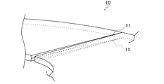
- FIG. 1 is a perspective view illustrating a part of an example of a filter retainer according to a first embodiment of the present invention.
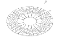
- FIG. 2 is a perspective view showing another example of the filter retainer according to the first embodiment of the present invention.
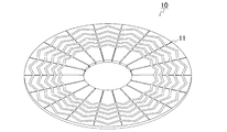
- FIG. 3 is a perspective view showing still another example of the filter retainer according to the first embodiment of the present invention.
- FIG. 4A is a cross-sectional view showing an example of a filter using the filter retainer of the first embodiment of the present invention, and FIG. 4B uses the filter retainer of the first embodiment of the present invention.
- FIG. 4C is a cross-sectional view showing still another example of the filter using the filter retainer according to Embodiment 1 of the present invention, and FIG.
- FIG. 5 is a perspective view showing a filter retainer according to Embodiment 2 of the present invention.
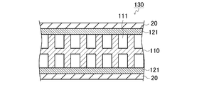
- FIG. 6 is a cross-sectional view showing an example of a filter using a conventional filter retainer.
- grooves are formed on both surfaces of the filter retainer as the flow path, and the width of the groove on the outer peripheral side is the width of the groove on the center side in the radial direction of the filter retainer.
- the vertical cross-sectional area of the flow path on the outer peripheral side may be narrower than the vertical cross-sectional area of the flow path on the center side.
- grooves are formed on both surfaces of the filter retainer as the flow path, and the depth of the groove on the outer peripheral side in the radial direction of the filter retainer is that of the groove on the center side.
- the vertical cross-sectional area of the flow path on the outer peripheral side may be narrower than the vertical cross-sectional area of the flow path on the center side.
- columnar protrusions are formed on both surfaces of the filter retainer, and the number of protrusions per unit area on the outer peripheral side in the radial direction of the filter retainer
- the vertical cross-sectional area of the flow path on the outer peripheral side may be narrower than the vertical cross-sectional area of the flow path on the center side.
- an angle formed between the side wall and the bottom of the flow path is an obtuse angle, or the side wall and the bottom of the flow path are connected by an arc.
- At least the bottom of the flow path may have an arc shape.
- the flow path is preferably formed by chemical etching.
- an angle formed by a side wall of the flow path of the filter medium and the filter retainer is an obtuse angle, or the flow path of the filter retainer is connected to the filter medium by an arc.
- FIG. 1 is a perspective view showing a part of an example of a filter retainer of the present embodiment.
- the filter retainer 10 of the present embodiment is a substantially circular plate having grooves 11 formed as flow paths on both surfaces.
- the material for forming the filter retainer 10 is not particularly limited, and for example, a stainless steel (SUS) plate can be used from the viewpoint of corrosion resistance, mechanical strength, heat resistance, and the like.
- the size of the filter retainer 10 is, for example, in the range of 50 to 500 mm in diameter and in the range of 1 to 10 mm in thickness, preferably in the range of 75 to 450 mm in diameter and in the range of 1.5 to 8 mm in thickness. More preferably, the diameter is in the range of 100 mm to 400 mm, and the thickness is in the range of 2 mm to 6 mm.
- the two grooves (flow channels) 11 formed on both surfaces of the filter retainer 10 are narrower and shallower in the radial direction from the center toward the outside. Thereby, in the radial direction of the filter retainer 10 of the present embodiment, the vertical cross-sectional area of the flow path 11 on the outer peripheral side is narrower than the vertical cross-sectional area of the flow path 11 on the center side.
- the filtered fluid flows through the groove (flow path) 11 from the outer peripheral side toward the center side.
- the width of the center side end of the groove (flow path) 11 is, for example, in the range of 0.5 mm to 6 mm, preferably in the range of 1 mm to 4 mm, and more preferably in the range of 1.5 mm to 2 mm. is there.
- the width of the outer end of the groove (flow path) 11 is, for example, in the range of 0 mm to 2 mm, preferably in the range of 0.2 mm to 1.5 mm, and more preferably in the range of 0.5 mm to 1 mm. It is.
- the depth of the center side end of the groove (flow path) 11 is, for example, in the range of 0.5 mm to 5 mm, preferably in the range of 1 mm to 4.5 mm, and more preferably in the range of 1.5 mm to 4 mm. Range. As shown in FIG. 1, the depth of the center side end of the groove (channel) 11 is half the thickness of the filter retainer 10, and two grooves (channel) formed on both surfaces of the filter retainer 10. ) 11 may be integrated at the center side end. However, the filter retainer 10 of this embodiment is not limited to this, and the depth of the center side end of the groove (flow path) 11 may be less than half the thickness of the filter retainer 10.
- the depth of the outer end of the groove (channel) 11 is, for example, in the range of 0 mm to 2 mm, preferably in the range of 0.2 mm to 1.5 mm, and more preferably in the range of 0.3 mm to 1 mm. It is a range.
- FIG. 1 only two grooves (channels) 11 are shown on each surface of the filter retainer 10 for the sake of clarity.
- the plurality of grooves (flow paths) 11 are arranged at equal intervals in the circumferential direction.
- the number of grooves (flow paths) 11 on each surface of the filter retainer 10 is, for example, in the range of 20 to 360.
- the groove (flow path) 11 is linear.
- the filter retainer 10 of the present embodiment only needs to have a groove (flow path) 11 that is narrower in width and shallower in depth in the radial direction from the center to the outside.
- the (flow path) 11 may have a curved shape such as an arc shape, or, as shown in FIG. 2, grooves (flow paths) 11 extending linearly in the adjacent radial direction are provided in the circumferential direction. You may have a groove
- a V-shaped groove (flow path) is formed between one surface of the filter retainer 10 and the other between adjacent grooves (flow paths) 11 extending linearly in the radial direction. It may be formed so as to be staggered in terms of.
- the width of the groove (flow channel) 11 on the outer side and the center side is the same, and only the depth of the groove (flow channel) 11 is made shallower from the center toward the outer side.
- the vertical cross-sectional area of the flow path 11 on the outer peripheral side may be narrower than the vertical cross-sectional area of the flow path 11 on the center side.
- the depth of the groove (flow path) 11 on the outer side and the center side is the same, and the width of the groove (flow path) 11 is only narrowed from the center toward the outer side.
- the vertical cross-sectional area of the outer peripheral flow path 11 may be narrower than the vertical cross-sectional area of the central flow path 11.
- the manufacturing method of the filter retainer 10 of the present embodiment is not particularly limited.
- the filter retainer 10 is manufactured by forming a groove (flow path) on a forming material such as a substantially circular SUS plate by chemical etching, press working, or the like. it can.
- the conditions for the chemical etching are not particularly limited, and may be set as appropriate according to the plate thickness, working method, and the like, but the following conditions can be given as an example.
- the filter retainer 10 of the present embodiment is a filter made by arranging filter media on both sides, or a plurality of layers are laminated with a spacer interposed therebetween, for filtering molten polymer and viscous fluid. It can be used as a filter for filtration.
- the filter medium is not particularly limited, and a conventionally known filter medium can be used. For example, a sheet-like SUS nonwoven fabric can be used.
- the vertical cross-sectional area of the flow path is narrower on the outer peripheral side where the filtration fluid is less and the flow rate tends to be slower than the central side where the filtration fluid is concentrated. Thus, it is possible to increase the flow rate of the filtration fluid on the outer peripheral side and suppress the retention of the filtration fluid.
- FIG. 6 shows an example of a filter 130 using a conventional filter retainer 110.
- the filter 130 has a configuration in which a porous body 121 such as a punching metal is disposed on both surfaces of a filter retainer 110 and a filter medium 20 is laid thereon.
- a porous body 121 such as a punching metal
- FIG. 6 in the conventional filter retainer 110, in the cross section of the flow path 111, when the angle formed between the side wall and the bottom of the flow path 111 is a right angle or when the filter retainer 110 is a wire mesh, There were places with sharp angles such as wedges in the channel.
- the filter retainer 10 of this embodiment in the cross section of the flow path 11, the angle formed by the side wall and the bottom of the flow path 11 is an obtuse angle, or the side wall and the bottom of the flow path 11 are connected by an arc. Preferably it is.
- the angle formed by the filter medium and the side wall of the flow path 11 of the filter retainer 10 is an obtuse angle, or the flow path 11 of the filter retainer 10 is It is preferable to be connected to the filter medium by an arc. Thereby, the retention inhibitory effect of filtration fluid can further be heightened.
- the filter retainer 10 of the present embodiment in which the channel 11 has such a cross-sectional shape and the filter 30 using the same will be described.
- the filter 30 has the filter medium 20 on both surfaces of the filter retainer 10 of the present embodiment.
- the angle formed between the side wall and the bottom of the flow path 11 is an obtuse angle in the cross section of the flow path 11.
- the bottom of the flow path 11 has an arc shape in the cross section of the flow path 11.
- the angle formed between the filter medium 20 and the side wall of the flow path 11 of the filter retainer 10 is an obtuse angle.
- the circled portion may be arcuate.
- the entire flow path 11 has an arc shape in the cross section of the flow path 11 of the filter retainer 10.
- the cross section of the flow path 11 it is particularly preferable that the entire flow path 11 has an arc shape because there is no right or acute corner in the flow path 11.
- the cross section of the flow path 11 can be shaped as shown in FIG.
- the two flow paths 11 formed on both surfaces of the filter retainer 10 may be integrated at the center side end.
- the filter retainer 10 of the present embodiment has many smooth portions on the surface and suppresses deformation of the filter medium 20 compared to a conventional wire mesh or the like, so that the filter retainer 10 and the filter medium 20 are not deformed. There is no need to interpose a porous material such as punching metal. For this reason, if the filter retainer 10 of this embodiment is used, the total resistance inside the filter can be reduced, and the retention of the filtered fluid can also be suppressed in this respect. Further, if the filter retainer 10 of the present embodiment is used, the number of constituent members of the filter is reduced, and the manufacturing cost of the filter can be reduced. Furthermore, the filter retainer 10 of the present embodiment can be manufactured easily and accurately because, for example, the material is only one SUS plate and the number of work steps in manufacturing is small.
- FIG. 5 is a perspective view showing the filter retainer of the present embodiment.
- a plurality of columnar protrusions 12 are arranged on both surfaces in the circumferential direction, and the rows of the protrusions 12 are arranged as four concentric annular rows. Yes.
- the space between the adjacent protrusions 12 serves as a flow path for the filtration fluid. The filtered fluid flows through the flow path from the outer peripheral side toward the center side.
- the number of the protrusions 12 per unit area on the outer peripheral side is larger than the number of the protrusions 12 per unit area on the central side, so that the flow path on the outer peripheral side Is narrower than the vertical cross-sectional area of the flow path on the center side.
- the annular rows of the protrusions 12 are not limited to the four rows shown in FIG.
- the number of projections 12 per unit area in the most central annular row is, for example, in the range of 200,000 pieces / m 2 to 800,000 pieces / m 2 , and preferably 300,000 pieces / m 2 to 700,000 pieces.
- / m is in the range of 2, more preferably in the range of 400,000 / m 2 ⁇ 60 thousands / m 2.
- the number of protrusions 12 in the outermost annular row per unit area is, for example, in the range of 300,000 pieces / m 2 to 1.2 million pieces / m 2 , and preferably 500,000 pieces / m 2 to 1 million pieces / m 2.
- the range is m 2 , more preferably 600,000 pieces / m 2 to 900,000 pieces / m 2 .
- the filter retainer of the present embodiment can be manufactured in the same manner as the filter retainer of the first embodiment.
- the method of using the filter retainer of the present embodiment is also the same as that of the filter retainer of the first embodiment.
- the vertical cross-sectional area of the flow path is narrow on the outer peripheral side where the filtration fluid is less and the flow rate tends to be slower than the central side where the filtration fluid is concentrated. It is possible to increase the flow rate of the filtration fluid on the outer peripheral side and suppress the retention of the filtration fluid.
- the number of protrusions on the outer peripheral side and the center side can be the same, and the volume of each protrusion can be increased from the center toward the outer side.
- the vertical cross-sectional area of the path can be made smaller than the vertical cross-sectional area of the flow path on the center side, and the same effect as the filter retainer of this embodiment can be obtained.
- the volume per unit area of the protrusions in the most central annular row is, for example, in the range of 80 cm 3 / m 2 to 3000 cm 3 / m 2 , preferably 240 cm 3 / m 2 to 2400 cm 3.
- / m is in the range of 2, more preferably in the range of 470 cm 3 / m 2 ⁇ 1800 cm 3 / m 2, the volume per unit area of the projections in the outermost annular row, for example, 0 cm 3 / m 2 in the range of ⁇ 1800cm 3 / m 2, preferably in the range of 80cm 3 / m 2 ⁇ 1200cm 3 / m 2, more preferably in the range of 140cm 3 / m 2 ⁇ 700cm 3 / m 2.
- Such a filter retainer can be manufactured and used in the same manner as the filter retainer of the first embodiment.
- the filter retainer and the filter of the present invention it is possible to obtain a filter retainer and a filter that can suppress the retention of the filtered fluid.
- the use of the filter retainer and the filter of the present invention is not particularly limited, and can be widely used for, for example, a filter for molten polymer filtration and a viscous fluid filtration.
Landscapes
- Chemical & Material Sciences (AREA)
- Chemical Kinetics & Catalysis (AREA)
- Filtering Materials (AREA)
- Filtration Of Liquid (AREA)
Abstract
Priority Applications (6)
| Application Number | Priority Date | Filing Date | Title |
|---|---|---|---|
| HK16100534.5A HK1212647A1 (zh) | 2013-04-26 | 2013-07-05 | 过滤器用保持架及使用其的过滤器 |
| JP2015513477A JP6084686B2 (ja) | 2013-04-26 | 2013-07-05 | フィルター用リテーナ及びそれを用いたフィルター |
| EP13882654.0A EP2990088A4 (fr) | 2013-04-26 | 2013-07-05 | Porte-filtre pour filtre et filtre utilisant celui-ci |
| KR1020157030236A KR20160002802A (ko) | 2013-04-26 | 2013-07-05 | 필터용 리테이너 및 그것을 사용한 필터 |
| US14/783,032 US20160051911A1 (en) | 2013-04-26 | 2013-07-05 | Retainer for filter, and filter using same |
| CN201380075013.9A CN105050683A (zh) | 2013-04-26 | 2013-07-05 | 过滤器用保持架及使用其的过滤器 |
Applications Claiming Priority (2)
| Application Number | Priority Date | Filing Date | Title |
|---|---|---|---|
| JP2013-093489 | 2013-04-26 | ||
| JP2013093489 | 2013-04-26 |
Publications (1)
| Publication Number | Publication Date |
|---|---|
| WO2014174690A1 true WO2014174690A1 (fr) | 2014-10-30 |
Family
ID=51791291
Family Applications (1)
| Application Number | Title | Priority Date | Filing Date |
|---|---|---|---|
| PCT/JP2013/068464 Ceased WO2014174690A1 (fr) | 2013-04-26 | 2013-07-05 | Porte-filtre pour filtre et filtre utilisant celui-ci |
Country Status (8)
| Country | Link |
|---|---|
| US (1) | US20160051911A1 (fr) |
| EP (1) | EP2990088A4 (fr) |
| JP (1) | JP6084686B2 (fr) |
| KR (1) | KR20160002802A (fr) |
| CN (1) | CN105050683A (fr) |
| HK (1) | HK1212647A1 (fr) |
| TW (1) | TWI601566B (fr) |
| WO (1) | WO2014174690A1 (fr) |
Cited By (1)
| Publication number | Priority date | Publication date | Assignee | Title |
|---|---|---|---|---|
| WO2016203908A1 (fr) * | 2015-06-16 | 2016-12-22 | 長瀬産業株式会社 | Milieu filtrant, élément de filtre comprenant le milieu filtrant, et procédé de fabrication de film de résine à l'aide du milieu filtrant |
Families Citing this family (2)
| Publication number | Priority date | Publication date | Assignee | Title |
|---|---|---|---|---|
| CN113019474A (zh) * | 2021-04-16 | 2021-06-25 | 上海理振工业技术有限公司 | 一种流体旋导片、流体滤柱装置及流体净化装置 |
| US12220657B2 (en) * | 2021-04-30 | 2025-02-11 | Pall Corporation | Filter disk segments |
Citations (9)
| Publication number | Priority date | Publication date | Assignee | Title |
|---|---|---|---|---|
| JPS6275814U (fr) * | 1985-10-31 | 1987-05-15 | ||
| JPS644210A (en) * | 1987-03-30 | 1989-01-09 | Kiyuno Inc | Filter cartridge |
| JPH01132201U (fr) * | 1988-03-01 | 1989-09-07 | ||
| JPH0347007U (fr) * | 1989-09-11 | 1991-04-30 | ||
| JPH0621708U (ja) * | 1992-08-28 | 1994-03-22 | フィルトレーション株式会社 | 濾材支持体 |
| JPH0810521A (ja) | 1994-06-27 | 1996-01-16 | Nippon Seisen Co Ltd | ポリマー用濾過装置 |
| JPH1176721A (ja) | 1997-09-01 | 1999-03-23 | Nippon Seisen Co Ltd | 積層金属フィルター |
| JP2001009213A (ja) | 1999-06-29 | 2001-01-16 | Nippon Seisen Co Ltd | 濾過用フィルター |
| JP2009279517A (ja) * | 2008-05-22 | 2009-12-03 | Nagase & Co Ltd | フィルター用リテーナ |
Family Cites Families (7)
| Publication number | Priority date | Publication date | Assignee | Title |
|---|---|---|---|---|
| DE1096331B (de) * | 1953-04-01 | 1961-01-05 | Bosch Gmbh Robert | Stuetzkoerper fuer scheibenfoermige, stapelbare Filterelemente |
| DE1116193B (de) * | 1953-10-02 | 1961-11-02 | Jacques Muller | Stapelbares Filterelement |
| US3648844A (en) * | 1969-07-24 | 1972-03-14 | Ametek Inc | Plastic filter leaf with separator channels |
| CN2188013Y (zh) * | 1993-11-23 | 1995-01-25 | 严益民 | 伞形扇面熔浆过滤器 |
| JP3429360B2 (ja) * | 1994-03-23 | 2003-07-22 | 株式会社東海スプリング製作所 | フィルター用ハブリング |
| JP3411100B2 (ja) * | 1994-07-25 | 2003-05-26 | 長瀬産業株式会社 | フィルター用支持板の製造方法およびその方法により製造されたフィルター用支持板 |
| CN202410302U (zh) * | 2011-12-31 | 2012-09-05 | 上海闰铭精密技术有限公司 | 袋式过滤器的滤袋支撑架 |
-
2013
- 2013-07-05 CN CN201380075013.9A patent/CN105050683A/zh active Pending
- 2013-07-05 JP JP2015513477A patent/JP6084686B2/ja active Active
- 2013-07-05 US US14/783,032 patent/US20160051911A1/en not_active Abandoned
- 2013-07-05 WO PCT/JP2013/068464 patent/WO2014174690A1/fr not_active Ceased
- 2013-07-05 HK HK16100534.5A patent/HK1212647A1/zh unknown
- 2013-07-05 KR KR1020157030236A patent/KR20160002802A/ko not_active Ceased
- 2013-07-05 EP EP13882654.0A patent/EP2990088A4/fr not_active Withdrawn
- 2013-07-18 TW TW102125740A patent/TWI601566B/zh not_active IP Right Cessation
Patent Citations (9)
| Publication number | Priority date | Publication date | Assignee | Title |
|---|---|---|---|---|
| JPS6275814U (fr) * | 1985-10-31 | 1987-05-15 | ||
| JPS644210A (en) * | 1987-03-30 | 1989-01-09 | Kiyuno Inc | Filter cartridge |
| JPH01132201U (fr) * | 1988-03-01 | 1989-09-07 | ||
| JPH0347007U (fr) * | 1989-09-11 | 1991-04-30 | ||
| JPH0621708U (ja) * | 1992-08-28 | 1994-03-22 | フィルトレーション株式会社 | 濾材支持体 |
| JPH0810521A (ja) | 1994-06-27 | 1996-01-16 | Nippon Seisen Co Ltd | ポリマー用濾過装置 |
| JPH1176721A (ja) | 1997-09-01 | 1999-03-23 | Nippon Seisen Co Ltd | 積層金属フィルター |
| JP2001009213A (ja) | 1999-06-29 | 2001-01-16 | Nippon Seisen Co Ltd | 濾過用フィルター |
| JP2009279517A (ja) * | 2008-05-22 | 2009-12-03 | Nagase & Co Ltd | フィルター用リテーナ |
Non-Patent Citations (1)
| Title |
|---|
| See also references of EP2990088A4 |
Cited By (2)
| Publication number | Priority date | Publication date | Assignee | Title |
|---|---|---|---|---|
| WO2016203908A1 (fr) * | 2015-06-16 | 2016-12-22 | 長瀬産業株式会社 | Milieu filtrant, élément de filtre comprenant le milieu filtrant, et procédé de fabrication de film de résine à l'aide du milieu filtrant |
| JPWO2016203908A1 (ja) * | 2015-06-16 | 2017-06-29 | 長瀬産業株式会社 | 濾材、濾材を備えたフィルタ部材及び濾材を用いて樹脂フィルムを製造する方法 |
Also Published As
| Publication number | Publication date |
|---|---|
| EP2990088A4 (fr) | 2016-12-21 |
| EP2990088A1 (fr) | 2016-03-02 |
| KR20160002802A (ko) | 2016-01-08 |
| HK1212647A1 (zh) | 2016-06-17 |
| TW201440865A (zh) | 2014-11-01 |
| JP6084686B2 (ja) | 2017-02-22 |
| US20160051911A1 (en) | 2016-02-25 |
| CN105050683A (zh) | 2015-11-11 |
| TWI601566B (zh) | 2017-10-11 |
| JPWO2014174690A1 (ja) | 2017-02-23 |
Similar Documents
| Publication | Publication Date | Title |
|---|---|---|
| JP7086098B2 (ja) | 濾過巻き要素のための段階的なスペーサ | |
| JP2017503650A5 (fr) | ||
| JP6084686B2 (ja) | フィルター用リテーナ及びそれを用いたフィルター | |
| JP6109584B2 (ja) | フィルター用リテーナ、フィルター及びフィルター用リテーナの製造方法 | |
| US12220657B2 (en) | Filter disk segments | |
| AU2020314462B2 (en) | Fluoroplastic support membrane | |
| KR20110020769A (ko) | 필터용 리테이너 | |
| KR20190044270A (ko) | 3층 구조의 공급 스페이서 및 이를 포함하는 역삼투막 필터 모듈 | |
| CN106482556B (zh) | 一种在角孔与换热装置之间有翅片的盒形层叠换热器 | |
| KR102715997B1 (ko) | 유로 스페이서 및 스파이럴형 막 엘리먼트 | |
| EP2942101A1 (fr) | Réacteur catalytique et procédé pour la fabrication d'un réacteur catalytique | |
| JP2009119447A (ja) | 積層多孔構造体 | |
| JP2008200607A (ja) | ディスクフィルタ | |
| US11192058B2 (en) | Honeycomb body for exhaust gas aftertreatment | |
| CN109341788A (zh) | 小型层流元件 | |
| CN107930238A (zh) | 支撑架及其采用支撑架支撑的过滤器 | |
| JP6195160B2 (ja) | 高粘度ポリマー用のフィルターエレメント | |
| WO2012093605A2 (fr) | Élément de filtration | |
| JPH0833805A (ja) | フィルター用支持板およびその製造方法 | |
| JPWO2021011217A5 (fr) | ||
| JP2018103121A5 (fr) | ||
| JP6476200B2 (ja) | オイルフィルタ | |
| JP2016182571A (ja) | ろ過モジュール | |
| JP6198139B2 (ja) | ポリマーフィルター用ハブ、及びこれを用いた高粘度ポリマー用のリーフフィルターエレメント。 | |
| JP2022053076A (ja) | 多孔金属板、及びフィルタ用リテーナ |
Legal Events
| Date | Code | Title | Description |
|---|---|---|---|
| WWE | Wipo information: entry into national phase |
Ref document number: 201380075013.9 Country of ref document: CN |
|
| 121 | Ep: the epo has been informed by wipo that ep was designated in this application |
Ref document number: 13882654 Country of ref document: EP Kind code of ref document: A1 |
|
| ENP | Entry into the national phase |
Ref document number: 2015513477 Country of ref document: JP Kind code of ref document: A |
|
| WWE | Wipo information: entry into national phase |
Ref document number: 2013882654 Country of ref document: EP |
|
| WWE | Wipo information: entry into national phase |
Ref document number: 14783032 Country of ref document: US |
|
| ENP | Entry into the national phase |
Ref document number: 20157030236 Country of ref document: KR Kind code of ref document: A |
|
| NENP | Non-entry into the national phase |
Ref country code: DE |