WO2014174765A1 - Dispositif de capture d'image et procédé de capture d'image - Google Patents
Dispositif de capture d'image et procédé de capture d'image Download PDFInfo
- Publication number
- WO2014174765A1 WO2014174765A1 PCT/JP2014/001837 JP2014001837W WO2014174765A1 WO 2014174765 A1 WO2014174765 A1 WO 2014174765A1 JP 2014001837 W JP2014001837 W JP 2014001837W WO 2014174765 A1 WO2014174765 A1 WO 2014174765A1
- Authority
- WO
- WIPO (PCT)
- Prior art keywords
- image
- imaging
- light
- data
- wavelength band
- Prior art date
- Legal status (The legal status is an assumption and is not a legal conclusion. Google has not performed a legal analysis and makes no representation as to the accuracy of the status listed.)
- Ceased
Links
Images


Classifications
-
- H—ELECTRICITY
- H04—ELECTRIC COMMUNICATION TECHNIQUE
- H04N—PICTORIAL COMMUNICATION, e.g. TELEVISION
- H04N5/00—Details of television systems
- H04N5/222—Studio circuitry; Studio devices; Studio equipment
- H04N5/262—Studio circuits, e.g. for mixing, switching-over, change of character of image, other special effects ; Cameras specially adapted for the electronic generation of special effects
- H04N5/265—Mixing
-
- G—PHYSICS
- G06—COMPUTING OR CALCULATING; COUNTING
- G06F—ELECTRIC DIGITAL DATA PROCESSING
- G06F18/00—Pattern recognition
- G06F18/20—Analysing
- G06F18/25—Fusion techniques
- G06F18/251—Fusion techniques of input or preprocessed data
-
- G—PHYSICS
- G06—COMPUTING OR CALCULATING; COUNTING
- G06T—IMAGE DATA PROCESSING OR GENERATION, IN GENERAL
- G06T5/00—Image enhancement or restoration
- G06T5/50—Image enhancement or restoration using two or more images, e.g. averaging or subtraction
-
- G—PHYSICS
- G06—COMPUTING OR CALCULATING; COUNTING
- G06V—IMAGE OR VIDEO RECOGNITION OR UNDERSTANDING
- G06V10/00—Arrangements for image or video recognition or understanding
- G06V10/10—Image acquisition
- G06V10/12—Details of acquisition arrangements; Constructional details thereof
- G06V10/14—Optical characteristics of the device performing the acquisition or on the illumination arrangements
- G06V10/143—Sensing or illuminating at different wavelengths
-
- H—ELECTRICITY
- H04—ELECTRIC COMMUNICATION TECHNIQUE
- H04N—PICTORIAL COMMUNICATION, e.g. TELEVISION
- H04N23/00—Cameras or camera modules comprising electronic image sensors; Control thereof
- H04N23/10—Cameras or camera modules comprising electronic image sensors; Control thereof for generating image signals from different wavelengths
- H04N23/11—Cameras or camera modules comprising electronic image sensors; Control thereof for generating image signals from different wavelengths for generating image signals from visible and infrared light wavelengths
-
- H—ELECTRICITY
- H04—ELECTRIC COMMUNICATION TECHNIQUE
- H04N—PICTORIAL COMMUNICATION, e.g. TELEVISION
- H04N23/00—Cameras or camera modules comprising electronic image sensors; Control thereof
- H04N23/95—Computational photography systems, e.g. light-field imaging systems
- H04N23/951—Computational photography systems, e.g. light-field imaging systems by using two or more images to influence resolution, frame rate or aspect ratio
-
- H—ELECTRICITY
- H04—ELECTRIC COMMUNICATION TECHNIQUE
- H04N—PICTORIAL COMMUNICATION, e.g. TELEVISION
- H04N25/00—Circuitry of solid-state image sensors [SSIS]; Control thereof
- H04N25/10—Circuitry of solid-state image sensors [SSIS]; Control thereof for transforming different wavelengths into image signals
- H04N25/11—Arrangement of colour filter arrays [CFA]; Filter mosaics
- H04N25/13—Arrangement of colour filter arrays [CFA]; Filter mosaics characterised by the spectral characteristics of the filter elements
- H04N25/131—Arrangement of colour filter arrays [CFA]; Filter mosaics characterised by the spectral characteristics of the filter elements including elements passing infrared wavelengths
-
- H—ELECTRICITY
- H04—ELECTRIC COMMUNICATION TECHNIQUE
- H04N—PICTORIAL COMMUNICATION, e.g. TELEVISION
- H04N25/00—Circuitry of solid-state image sensors [SSIS]; Control thereof
- H04N25/10—Circuitry of solid-state image sensors [SSIS]; Control thereof for transforming different wavelengths into image signals
- H04N25/11—Arrangement of colour filter arrays [CFA]; Filter mosaics
- H04N25/13—Arrangement of colour filter arrays [CFA]; Filter mosaics characterised by the spectral characteristics of the filter elements
- H04N25/133—Arrangement of colour filter arrays [CFA]; Filter mosaics characterised by the spectral characteristics of the filter elements including elements passing panchromatic light, e.g. filters passing white light
-
- H—ELECTRICITY
- H04—ELECTRIC COMMUNICATION TECHNIQUE
- H04N—PICTORIAL COMMUNICATION, e.g. TELEVISION
- H04N25/00—Circuitry of solid-state image sensors [SSIS]; Control thereof
- H04N25/10—Circuitry of solid-state image sensors [SSIS]; Control thereof for transforming different wavelengths into image signals
- H04N25/11—Arrangement of colour filter arrays [CFA]; Filter mosaics
- H04N25/13—Arrangement of colour filter arrays [CFA]; Filter mosaics characterised by the spectral characteristics of the filter elements
- H04N25/135—Arrangement of colour filter arrays [CFA]; Filter mosaics characterised by the spectral characteristics of the filter elements based on four or more different wavelength filter elements
- H04N25/136—Arrangement of colour filter arrays [CFA]; Filter mosaics characterised by the spectral characteristics of the filter elements based on four or more different wavelength filter elements using complementary colours
-
- G—PHYSICS
- G06—COMPUTING OR CALCULATING; COUNTING
- G06T—IMAGE DATA PROCESSING OR GENERATION, IN GENERAL
- G06T2207/00—Indexing scheme for image analysis or image enhancement
- G06T2207/20—Special algorithmic details
- G06T2207/20212—Image combination
- G06T2207/20221—Image fusion; Image merging
-
- G—PHYSICS
- G06—COMPUTING OR CALCULATING; COUNTING
- G06T—IMAGE DATA PROCESSING OR GENERATION, IN GENERAL
- G06T2207/00—Indexing scheme for image analysis or image enhancement
- G06T2207/30—Subject of image; Context of image processing
- G06T2207/30248—Vehicle exterior or interior
- G06T2207/30252—Vehicle exterior; Vicinity of vehicle
- G06T2207/30261—Obstacle
Definitions
- the present invention relates to an imaging apparatus and an imaging method for imaging a first image and a second image and performing image processing.
- Patent Document 1 an imaging device that images a predetermined subject at night or in an environment with poor visibility such as rain or fog has been used for monitoring or in-vehicle use.
- an object such as a pedestrian is detected by using an infrared image obtained by imaging infrared light in order to support driving of the driver under the above environment.
- a technique for highlighting an object is disclosed.
- the present invention has been made in view of the above circumstances, and an object thereof is to provide an imaging apparatus and an imaging method that can further improve the visibility of an object.
- a composite image is generated based on the first and second images obtained by imaging in the first and second wavelength bands, respectively.
- the image composition is generated, the object image in the second image is synthesized with the composition target image in the first image.
- the image pickup apparatus and the image pickup method according to the present invention can supplement the image quality that is insufficient in one image with another image, and thus can further improve the visibility of the object.
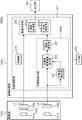
- FIG. 1 is a block diagram illustrating an example of the configuration of the imaging apparatus 1000 according to the first embodiment.
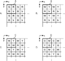
- FIG. 2 is a partial view of the optical filter group according to the embodiment. In FIG. 2, each optical filter is partially shown by looking at the optical filter group arranged in a matrix with a predetermined arrangement from the incident side.
- FIG. 2A is a diagram illustrating the RGBIr mode optical filter group 103 according to the first embodiment
- FIG. 2B is a diagram illustrating the WYRIr mode optical filter group 103 according to the first embodiment.
- FIG. 2C is a diagram illustrating a WYR type optical filter group 103a according to a second embodiment described later
- FIG. 2D is a diagram illustrating a CMYG type optical filter group 103a according to a second embodiment described later.
- an imaging apparatus 1000 includes, for example, an imaging unit 100, an image processing unit 200, an output unit 300, and an input unit 400.
- Imaging data is input from the imaging unit 100 to the image processing unit 200, and data after image processing is output from the image processing unit 200 to the output unit 300.
- the input unit 400 is connected to the image processing unit 200.
- the imaging unit 100 is a device that captures an image of a predetermined subject (object), for example, for monitoring or in-vehicle use.
- the imaging unit 100 includes, for example, an optical system 101, an optical filter group 103, and an image sensor 105.
- Light from the predetermined subject enters the optical filter group 103 through the optical system 101, and only light in a predetermined wavelength range is transmitted through the optical filter group 103 and enters the image sensor 105. More specifically, light in a predetermined wavelength range transmitted through the optical filter group 103 enters a plurality of photoelectric conversion elements included in the image sensor 105, and an analog electrical signal corresponding to the intensity of the incident light is imaged.
- the image is output from the sensor 105 to the image processing unit 200.
- the optical system 101 has an optical element such as one or a plurality of lenses, and forms, for example, light from the predetermined subject on the light receiving surface of the image sensor 105 via the optical filter group 103.
- the optical filter group 103 includes a plurality of optical filters that transmit light in a predetermined wavelength range with different center wavelengths.
- the optical filter group 103 is, for example, a red (R) filter that transmits red light, a green (G) filter that transmits green light, a blue (B) filter that transmits blue light, and infrared light.
- red (R) filter that transmits red light
- G green
- B blue
- Ir infrared
- Each of these four types of optical filters has a predetermined arrangement, for example, as shown in FIG. 2A. Thus, they are arranged in a matrix in two directions, the x direction and the y direction, which are orthogonal to each other.
- the optical filter group 103 of the present embodiment is similar to a so-called Bayer array type optical filter group, and one of two green filters included in the Bayer array type optical filter group is replaced with a near infrared filter.
- the configuration of the optical filter group 103 is specifically as follows.
- the optical filter group 103 includes, for example, the G filter at the (1,1) position, the R filter at the (2,1) position, the B filter at the (1,2) position, and the Ir filter at (2). , 2) are configured by arranging basic patterns (rectangular portions indicated by A in the figure) arranged in a matrix in two directions, the x direction and the y direction (hereinafter also referred to as RGBIr mode). Call).
- the optical filter group 103 includes, for example, a yellow (Y) filter that transmits yellow light (2, 2) at the position of a white (W) filter (1, 1) that transmits white light.
- the basic pattern (rectangular portion indicated by B in the figure) in which the R filter is disposed at the position (1,2) and the Ir filter is disposed at the position (2,2) at the position 1) is the x direction and y It may be configured by being arranged in a matrix in two directions (hereinafter also referred to as a WYRIr mode).
- the optical filters (R, G, B, Ir or W, Y, R, Ir filters) arranged in a matrix in the optical filter group 103 are arranged in a matrix included in the image sensor 105 described later.
- Each of the plurality of photoelectric conversion elements has a one-to-one correspondence.
- the photoelectric conversion element that receives green light is located at the position (1, 1)
- the photoelectric conversion element that receives red light is located at the position (2, 1), and blue.
- a basic pattern in which a photoelectric conversion element that receives light is disposed at a position (1, 2) and a photoelectric conversion element that receives near-infrared light is disposed at a position (2, 2), respectively, has the x direction and y It is arranged in a matrix in two directions.
- each of the plurality of photoelectric conversion elements receives light of a single color.
- the photoelectric conversion element located at (2, 2) in FIG. 2A receives only near-infrared light.
- one photoelectric conversion element since one photoelectric conversion element receives light of a single color, it generates a pixel value of that color, but does not generate pixel values of other colors.
- the pixel value of the other color in the photoelectric conversion element is the other color generated by the photoelectric conversion element that receives the light of the other color disposed around the photoelectric conversion element, for example. It is generated by interpolation using the pixel values.
- the blue pixel value in the photoelectric conversion element that receives near-infrared light located at (2, 2) is the photoelectric value existing at the positions (1, 2) and (3, 2) adjacent to this. It is calculated by performing an interpolation operation using the blue pixel value generated by the conversion element.
- the image sensor 105 has a plurality of photoelectric conversion elements arranged in a matrix that photoelectrically converts incident light and outputs a value corresponding to the intensity of the incident light.
- the plurality of photoelectric conversion elements in the image sensor 105 the plurality of photoelectric conversion elements that receive light through the R filter, the G filter, and the B filter respectively receive light in a wavelength region included in the first wavelength band.
- a plurality of first photoelectric conversion elements L1 that pick up an image and output first image pickup data D1.
- the plurality of photoelectric conversion elements that receive light through the Ir filter capture images of light in a second wavelength band that includes a wavelength band different from the first wavelength band.
- the light in the first wavelength band is visible light, and there are a plurality of light in the wavelength region included in the first wavelength band, which are red light, green light, and blue light.
- the light in the second wavelength band is infrared light (near infrared light in the present embodiment).
- the image sensor 105 is a single image sensor, and the plurality of first photoelectric conversion elements L1 and the plurality of second photoelectric conversion elements L2 are formed on the single image sensor 105.
- the image sensor 105 outputs the first imaging data D1 and the second imaging data D2 to the image processing unit 200 as analog electrical signals.
- the first image and the second image are images based on the first imaging data D1 and the second imaging data D2 output from one image sensor 105, respectively, and have the same size (same image size) and the same shape.
- the number of pixels of the first image and the second image is the same after the interpolation operation or the like as described above.
- the image sensor 105 of the present embodiment is, for example, a CMOS (Complementary Metal Oxide Semiconductor) type or a CCD (Charge Coupled) whose photoelectric conversion characteristic representing the characteristic of electric output with respect to the intensity of incident light is a linear characteristic or a linear logarithmic characteristic.
- Device type image sensor.
- the image sensor 105 has a linear logarithmic characteristic, since the dynamic range is wide, the dynamic range is appropriately compressed according to the dynamic range of the output unit 300.
- known conventional means are used, for example, disclosed in Japanese Patent No. 47367792.
- the image processing unit 200 detects a predetermined type of object from the second image based on the second imaging data D2, and includes the first image based on the first imaging data D1 and the second type including the predetermined type of object. Image processing for generating a composite image based on the second image based on the imaging data D2 is performed.
- the first image based on the first imaging data D1 is a so-called visible image
- the second image based on the second imaging data D2 is a so-called near infrared image.
- the image processing unit 200 includes a control calculation unit 211, for example.
- the control calculation unit 211 is connected to the image sensor 105, and the output from the control calculation unit 211 is output to the output unit 300.
- the control operation unit 211 performs various operations such as overall control of the imaging unit 100, the image processing unit 200, the output unit 300, and the input unit 400 and image composition.
- the control arithmetic unit 211 includes, for example, a CPU (Central Processing Unit), an EEPROM (Electrically Erasable Programmable Read Only Memory), a ROM (Read Only Memory), and a RAM (Random Access Memory).
- the control calculation unit 211 functionally includes a control unit 215, an object extraction unit 209, and an image composition unit 205 by executing an image processing program stored in the ROM.
- the object extraction unit 209 receives the second imaging data D2 from the image sensor 105, and the output of the object extraction unit 209 is output to the image composition unit 205.
- the image composition unit 205 receives the first imaging data D1 from the image sensor 105.
- the image composition unit 205 is connected to the object extraction unit 209, and the output of the image composition unit 205 is output to the output unit 300.
- the control unit 215 governs overall control of the imaging unit 100, the image processing unit 200, the output unit 300, and the input unit 400.
- the object extraction unit 209 detects a predetermined type of object T (hereinafter simply referred to as the object T) from the near-infrared image, and includes the object T from the near-infrared image based on the second imaging data D2.
- the object image G2 in the second image area is extracted.
- the object T is set in advance, and is, for example, a constant temperature organism such as a person or an animal, and may be plural.
- the shape of the object image G2 including the object T is a predetermined appropriate shape, for example, a rectangular shape.
- the shape of the object image G2 may be, for example, the shape of the object T itself.
- the object extraction unit 209 includes, for example, an object detection unit 201 and an object image region extraction unit 203.
- the object detection unit 201 receives the second imaging data D ⁇ b> 2 from the image sensor 105, and the output of the object detection unit 201 is output to the object image region extraction unit 203.
- the object image region extraction unit 203 receives the second imaging data D2 from the image sensor 105.
- the object image region extraction unit 203 is connected to the object detection unit 201, and the output of the object image region extraction unit 203 is output to the image composition unit 205.
- the object detection unit 201 detects a predetermined type of object T from the second image based on the second imaging data D2. More specifically, the object detection unit 201 detects the object T from the near-infrared image.
- the detection method of the target T in the target detection unit 201 uses, for example, a so-called pattern matching method that detects the target T using a predetermined template in the form of the target T (a constant temperature organism such as a person or an animal). (For example, refer to Japanese Patent Application Laid-Open No. 2004-145660).
- Another method for detecting the object T is, for example, creating an edge direction histogram indicating the degree of sharpness of the edge of the image for all pixels of the infrared image, and the degree of sharpness of the edge and the corresponding pixel.
- a method of detecting the target T by estimating the shape may be used.
- a boosting method machine learning algorithm or the like may be used to improve detection accuracy (for example, Takayoshi Yamashita, Hironobu Fujiyoshi, “Features Effective for Specific Object Recognition”, Information Processing Society of Japan) Research report, CVIM 165, November, 2008, pp. 221-236).
- the object detection unit 201 detects the object T as described above, and includes the detected object T, for example, an area of the object image G2 in the second image based on the second imaging data D2.
- Information is output to the object image region extraction unit 203.
- the area information is information representing the range of the object image G2 in the second image.
- the area information is, for example, each pixel coordinate (hereinafter, also referred to as vertex coordinate) corresponding to each of the four vertices in the rectangle of the object image G2.
- the coordinate value of the pixel in the captured image based on the captured image data is, for example, the pixel at one of the four vertices in the rectangle of the captured image as the origin, the longitudinal direction of the image as the x-axis direction, and the shortness of the image. It is a coordinate value in an xy orthogonal coordinate system or the like in which the hand direction is the y-axis direction.
- the object image area extraction unit 203 extracts the object image G2 from the second image based on the second imaging data D2. More specifically, the object image region extraction unit 203 extracts the object image G2 from the near-infrared image.
- the object image area extraction unit 203 sets a pixel value of an area excluding the second image area r2 (object image G2) in the near-infrared image based on the area information to a predetermined constant value.
- a mask image M is created by converting to.
- the object image region extraction unit 203 extracts the object image G2 from the near-infrared image, and outputs a mask image M including the object image G2 to the image composition unit 205.
- the predetermined constant value is, for example, zero.
- the region information other than the second image region r2 of the object image G2 is masked (blackened), so that the region information is substantially superimposed on the mask image M.
- the object image region extraction unit 203 stores, for example, a near-infrared image corresponding to the region information until the region information is input from the object detection unit 201 to the object image region extraction unit 203.
- the region information and the near-infrared image corresponding to the region information are synchronized.
- the image composition unit 205 generates a composite image based on the first image based on the first image data D1 and the second image based on the second image data. More specifically, the image composition unit 205 transfers the object image G2 in the second image area r2 including the object T in the second image to the second image area r2 in the first image. The image is combined with the image to be combined G1 in the corresponding first image region r1.
- the image composition unit 205 in the present embodiment synthesizes the object image G2 extracted by the object extraction unit 209 with the composition target image G1, and outputs the combined image data to the output unit 300. . More specifically, the image synthesizing unit 205 synthesizes the mask image M (the same shape, the same size, and the same number of pixels as the first image) for each corresponding pixel to the visible image that is the first image. Thus, the object image G2 is synthesized with the synthesis target image G1 between the rectangular second image region r2 and the rectangular first image region r1 having the same vertex coordinates as the second image region r2. .
- the image composition unit 205 adds pixel values of pixels having the same coordinates between the visible image and the mask image M, and synthesizes the object image G2 with the visible image. .
- the image composition unit 205 stores, for example, a visible image corresponding to the mask image M until the mask image M is input from the object extraction unit 209 to the image composition unit 205, and the mask image M and the mask image M are stored. Synchronize the visible image corresponding to.
- the image composition unit 205 includes, for example, a luminance composition unit 205a and a chromaticity correction unit 205b.
- the image composition unit 205 performs first brightness data representing the brightness included in the first image data D1 and second representing the brightness included in the second image data D2.
- the luminance data is synthesized by the luminance synthesis unit 205a.
- the luminance data is, for example, a luminance value calculated in the following (Expression 1), and the luminance synthesis unit 205a performs, for example, the first luminance of the synthesis target image G1 in the first image for each corresponding pixel.
- the composite luminance value is calculated by adding the second luminance value of the object image G2 extracted from the second image to the value.
- the image composition unit 205 converts the chromaticity data representing the chromaticity included in the first imaging data D1 into the color according to the composition of the second brightness data of the object image G2 and the first brightness data of the composition target image G1. Correction is performed by the degree correction unit 205b.
- the chromaticity data is, for example, the chromaticity value calculated in the following (Expression 1), and the chromaticity correction unit 205b performs synthesis in the first image, which is a visible image, for each corresponding pixel.
- the output unit 300 is a display device that outputs the image synthesized by the image synthesis unit 205.
- the display device is, for example, an LCD (Liquid Crystal Display) or the like, and is disposed, for example, on a dashboard in front of a driver's seat of a car, in a monitoring room, or the like.
- the display device is a head mounted display.
- the input unit 400 is an input device such as a dip switch or a push switch for inputting information to the imaging apparatus 1000.
- FIG. 3 is an operation flowchart of the imaging apparatus 1000 according to the first embodiment.
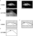
- FIG. 4 is a diagram for explaining a visible image, a near-infrared image, and a composite image according to the first embodiment.
- the optical system 101 forms an optical image of the subject on the light receiving surface of the image sensor 105 via the optical filter group 103.
- the first photoelectric conversion element L1 captures an optical image of the subject with visible light and outputs first imaging data D1
- the second photoelectric conversion element L2 captures an optical image of the subject with near-infrared light.
- the second imaging data D2 is output.
- red light, green light, and blue light signals are output from the plurality of first photoelectric conversion elements L1 of the image sensor 105 as the first imaging data D1.
- Each is output and A / D converted (analog-digital converted).
- a luminance value (first luminance value) Y and chromaticity values (first chromaticity values) Cb and Cr are expressed by the following (formulas) using the red value R, the green value G, and the blue value B, which are the respective digital values. Conversion is performed using the conversion formula represented by 1) (step S1).
- the white light, yellow light, and red light signals are A in the conversion formulas expressed by the following (formula 2) to (formula 4).
- the red value R, the green value G, and the blue value B are calculated using the digital values w, y, and r that have been subjected to the / D conversion, and then the first luminance value and the first color are calculated using (Equation 1). A degree value is calculated.
- ir is a digital value obtained by A / D converting a detection signal (analog output) of infrared light.
- the target object detection unit 201 detects the target object T from the near-infrared image, and the target object image region extraction unit 203 uses the predetermined constant value to determine a region excluding the target object image G2 from the near-infrared image.
- a masked mask image M is generated.
- the image composition unit 205 composites the mask image M with the visible image.
- the synthesized brightness value is calculated in the brightness synthesizer 205a (step S3). That is, the luminance composition unit 205a adds the luminance value of the synthesis target image G1 and the luminance value of the target image G2 (by synthesizing the first luminance data and the second luminance data), thereby synthesizing.
- a luminance value is calculated.
- IR is a digital value obtained by A / D-converting a near-infrared light signal (analog output) output from the image sensor 105, and more specifically, a luminance value in the mask image M.
- the optical filter group 103 is in the WYRIr mode
- weighting may be performed for addition of digital values (IR, ir) of near infrared light.
- IR digital values
- the chromaticity correction unit 205b corrects the chromaticity as the luminance of the synthesized image is converted from the first luminance value to the synthetic luminance value (step S5).
- the image composition unit 205 converts the luminance value Y ′, the chromaticity values Cb ′, and Cr ′ into the red value R ′, the green value G ′, and the conversion expression represented by (Equation 5) below. Conversion to a blue value B ′ (step S7).
- the image composition unit 205 performs gamma correction according to the display characteristics of the display device (output unit 300) for each of the red value R ′, the green value G ′, and the blue value B ′ (step S9).
- the red value, the green value, and the blue value after the gamma correction are output to the output unit 300.
- the output unit 300 which is a display device, receives the input of the red value, the green value, and the blue value after the gamma correction, and displays a composite image (step S11).
- FIG. 4 shows a first image (FIGS. 4A and 4D) which is a visible image based on the first imaging data D1, and a near red color based on the second imaging data D2 including the target T (broken line rectangular portion (second image region)).
- the second image (FIGS. 4B and 4E), which is an outer image, and the image (FIGS. 4C and 4F) in which the first image and the mask image M are combined in the image combining unit 205 are illustrated.
- 4A to 4C are actual captured images
- FIGS. 4D to 4F are schematic diagrams in which characteristic portions in the captured images of FIGS. 4A to 4C are extracted.
- FIG. 4A to 4D are actual captured images
- FIGS. 4D to 4F are schematic diagrams in which characteristic portions in the captured images of FIGS. 4A to 4C are extracted.
- FIG. 4A is a visible image obtained by imaging light in the first wavelength band, and therefore is an image in which the road and bushes on one side of the road are imaged in the dark.
- the part that is illuminated is imaged.
- FIG. 4D a portion illuminated by the road, the bush, and the illumination, which is a characteristic portion of the captured image of FIG. 4A, is represented by a solid line.
- FIG. 4D hatching indicating darkness is added.
- FIG. 4B is a near-infrared image obtained by imaging light in the second wavelength band, and thus is an image in which the road and the bushes on both sides of the road are dimly captured. Human and animal types are imaged with good brightness.
- FIG. 4B is a near-infrared image obtained by imaging light in the second wavelength band, and thus is an image in which the road and the bushes on both sides of the road are dimly captured. Human and animal types are imaged with good brightness.
- FIG. 4E the road, the bush, and the human and animal types, which are characteristic portions of the captured image of FIG. 4B, are represented by solid lines. Note that the dim points in FIG. 4B are not represented in FIG. 4E.
- FIG. 4C is an image obtained by combining FIG. 4A and a mask image M (not shown) obtained by masking the region excluding the broken-line rectangular portion of FIG. 4B with the predetermined constant value. Human and animal patterns are projected with high brightness in an image in which a bush on the side of the road and a portion illuminated by light near the center of the image appear.
- FIG. 4F shows the characteristic portions of the captured image of FIG. 4C, that is, the road, the bush, the portion illuminated by the illumination, and the types of the person and the animal by solid lines. In FIG. 4F, hatching indicating darkness is added.
- FIG. 4C and FIG. 4F displays the object T, which has poor visibility in the visible images of FIG. 4A and FIG. 4D, with higher visibility (the broken-line rectangular portion in FIG. 4C and FIG. 4F (first 1 image area)).
- FIG. 5 is a block diagram illustrating an example of a configuration of the imaging apparatus 1000a according to the second embodiment.
- FIG. 6 is a diagram for explaining a visible image, a near-infrared image, and a composite image according to the second embodiment.
- the imaging apparatus 1000 a according to the second embodiment is different from the imaging apparatus 1000 according to the first embodiment described above in that, for example, the imaging unit 100 a is used instead of the imaging unit 100, and the image processing is performed instead of the image processing unit 200. Part 200a.
- the following description will be focused on differences from the first embodiment.
- the same thing as the structure of 1st Embodiment is attached
- the imaging unit 100a has two separate image sensors. Accordingly, the imaging unit 100a includes, for example, an optical system 101a, an optical system 101b, an optical filter group 103a, a first image sensor 105a, and a second image sensor 105b.
- the imaging unit 100a includes, for example, an optical system 101a, an optical system 101b, an optical filter group 103a, a first image sensor 105a, and a second image sensor 105b.
- Light from the predetermined subject enters the optical filter group 103a through the optical system 101a, and only the light in the predetermined wavelength range is transmitted through the optical filter group 103a and enters the first image sensor 105a.
- Light from the predetermined subject enters the second image sensor 105b through the optical system 101b.
- the optical system 101a is the same as the optical system 101.
- the optical system 101b is, for example, an infrared lens.
- the optical filter group 103a is, for example, a so-called RGGB type optical filter group having a Bayer array.
- the optical filter group 103a may be, for example, a so-called WYR type optical filter group illustrated in FIG. 2C.
- the WYR type optical filter group includes, for example, a white (W) filter at a position (1, 1), a yellow (Y) filter at a position (2, 1), and a red (R) filter (1, 2).
- the optical filter group 103a may be, for example, a so-called CMYG type complementary color filter group shown in FIG. 2D.
- C indicates cyan
- M indicates magenta
- Y indicates yellow
- G indicates green.
- the CMYG type optical filter group has, for example, a cyan (C) filter that transmits cyan light at a position (1, 1) and a magenta (M) filter that transmits magenta light at a position (2, 1).
- a basic pattern (rectangular portion indicated by D in the figure) in which the yellow (Y) filter is disposed at the position (1, 2) and the green (G) filter is disposed at the position (2, 2), respectively, in the x direction And arranged in a matrix in two directions of the y direction.
- the plurality of photoelectric conversion elements included in the first image sensor 105a receive light in the wavelength region included in the first wavelength band via the optical filter group 103a, thereby imaging the light in the wavelength region and performing first imaging.
- the first image sensor 105a is, for example, an image sensor similar to the image sensor 105, in which the photoelectric conversion characteristic is a linear characteristic or a linear logarithmic characteristic.
- the plurality of photoelectric conversion elements included in the second image sensor 105b receive light in a second wavelength band that includes a wavelength band different from the first wavelength band via the infrared lens, so that the second wavelength A plurality of second photoelectric conversion elements L2 that pick up light of a band and output second imaging data D2.
- the first image data 105 from the first image sensor 105a and the second image data D2 from the second image sensor 105b are output to the control calculation unit 211, respectively.
- the light in the wavelength region included in the first wavelength band is visible light
- the light in the second wavelength band is far infrared light.
- the plurality of first photoelectric conversion elements L1 captures light (red, green, and blue) in a plurality of wavelength regions included in the first wavelength band, and outputs first imaging data D1.
- the second image sensor 105b is a so-called quantum type or thermal type far infrared image sensor.
- the first image sensor 105a and the second image sensor 105b have substantially the same object to be imaged.
- the first image sensor 105a and the second image sensor 105b are fixed with a predetermined distance (baseline length) at an interval so that the optical axes are parallel to each other. Is done.
- the first image based on the first imaging data D1 of the first image sensor 105a and the second image based on the second imaging data D2 of the second image sensor 105b have the same size, the same shape, and the same pixel. Is a number.
- the image processing unit 200a includes an object extraction unit 209a instead of the object extraction unit 209.
- the object extraction unit 209a further includes a parallax correction unit 207 with respect to the object extraction unit 209. That is, the object extraction unit 209a includes, for example, the object detection unit 201, the object image region extraction unit 203, and the parallax correction unit 207, and the output of the object image region extraction unit 203 is input to the parallax correction unit 207.
- the output of the parallax correction unit 207 is input to the image composition unit 205.
- the control arithmetic unit 211 further functionally configures the parallax correction unit 207 by executing an image processing program corresponding to the parallax correction stored in the ROM.
- the parallax correction unit 207 has a visible image (first image) generated by the first imaging data D1 generated because the second image sensor 105b and the first image sensor 105b are separated and fixed by the base line length as in a so-called stereo camera.
- the parallax between the one image) and the far-infrared image (second image) based on the second imaging data D2 is corrected by a known conventional means. Note that this parallax correction may be executed, for example, by shifting a far-infrared image in the horizontal direction within the image. This shift amount is appropriately set in advance according to the baseline length.
- the parallax correction unit 207 shifts the object image G2 extracted by the object image region extraction unit 203 in the horizontal direction in the mask image M by the shift amount, blackens the part other than the object image G2, and horizontally A mask image M ′ after correcting the deviation is generated, and the mask image M ′ is output to the image composition unit 205 instead of the mask image M.
- the imaging apparatus 1000 a displays the object T with poor visibility in the visible image, as shown in FIG. 6, as in FIG. 4.
- FIG. 6 includes a first image (FIGS. 6A and 6D) that is a visible image based on the first imaging data D1, and a second object T (a broken-line rectangular portion (second image region)).
- Examples include a second image (FIGS. 6B and 6E) that is a far-infrared image based on the imaging data D2, and an image (FIGS. 6C and 6F) in which the first image and the mask image M are combined in the image combining unit 205.
- FIGS. 6D to 6F are schematic diagrams obtained by extracting feature portions from the captured images of FIGS. 6A to 6C. Since FIG.
- FIG. 6A is a visible image obtained by imaging light in the first wavelength band, it is an image in which the road and bushes on one side of the road are imaged in the dark. The part that is illuminated is imaged.
- FIG. 6D shows a solid line indicating a portion of the captured image of FIG. 6A that is illuminated by the road, the bush, and the illumination. In FIG. 6D, hatching indicating darkness is added.
- FIG. 6B is a far-infrared image obtained by imaging light in the second wavelength band, and thus is an image in which the road and the bushes on both sides of the road are dimly captured. Human and animal types are imaged with good brightness.
- FIG. 6E the road, the bush, and the human and animal types, which are characteristic portions of the captured image of FIG.
- FIG. 6B is represented by solid lines. Note that the dim points in FIG. 6B are not represented in FIG. 6E.
- FIG. 6C is an image obtained by combining FIG. 6A and a mask image M (not shown) obtained by masking the region excluding the broken-line rectangular portion of FIG. 6B with the predetermined constant value. Human and animal patterns are projected with high brightness in an image in which a bush on the side of the road and a portion illuminated by light near the center of the image appear.
- FIG. 6F shows the characteristic portions of the captured image of FIG. 6C, that is, the road, the bush, the portion that is illuminated, and the human and animal types in solid lines. In FIG. 6F, hatching indicating darkness is added.
- the object T that is poorly visible in the visible images of FIGS. 6A and 6D is displayed with higher visibility (the broken-line rectangles in FIGS. 6C and 6F). Part (first image area)).
- FIG. 7 is a block diagram illustrating an example of a configuration of an imaging apparatus 1000b according to the third embodiment.
- the imaging apparatus 1000b according to the third embodiment is different from the imaging apparatus 1000 according to the first embodiment in, for example, an imaging unit 100b instead of the imaging unit 100 and an image processing unit 200b instead of the image processing unit 200.
- an imaging unit 100b instead of the imaging unit 100
- an image processing unit 200b instead of the image processing unit 200.
- the following description will be focused on differences from the first embodiment or the second embodiment.
- the same thing as the structure of 1st Embodiment or 2nd Embodiment is attached
- the imaging unit 100b includes, for example, an optical system 101c, an optical system 101d, an optical filter group 103c, a third image sensor 105c, and a fourth image sensor 105d.
- the imaging unit 100b has two separate image sensors. Light from the predetermined subject enters the optical filter group 103c through the optical system 101c, and only light in a predetermined wavelength range is transmitted through the optical filter group 103c and enters the third image sensor 105c. Further, light from the predetermined subject enters the fourth image sensor 105d through the optical system 101d.
- the optical system 101c is an imaging optical system having a near infrared lens.
- the optical system 101d is an imaging optical system having a far infrared lens.
- the optical filter group 103c is a near infrared filter.
- the plurality of photoelectric conversion elements included in the third image sensor 105c receive the light in the wavelength region included in the first wavelength band via the optical filter group 103c, thereby imaging the light in the wavelength region and performing first imaging.
- the third image sensor 105c is, for example, an image sensor whose photoelectric conversion characteristics are linear characteristics or linear logarithmic characteristics.
- the plurality of photoelectric conversion elements included in the fourth image sensor 105d receive the second wavelength band including a wavelength band different from the first wavelength band via the far-infrared lens, whereby the second A plurality of second photoelectric conversion elements L2 that pick up light in the wavelength band and output second image data D2.
- the first image data D1 from the third image sensor 105c and the second image data D2 from the fourth image sensor 105d are output to the control calculation unit 211, respectively.
- the light in the wavelength region included in the first wavelength band is near infrared light
- the light in the second wavelength band is far infrared light.
- the fourth image sensor 105d is a so-called quantum type or thermal type far infrared image sensor.
- the third image sensor 105c and the fourth image sensor 105d have substantially the same imaging target.
- the third image sensor 105c and the fourth image sensor 105d have a predetermined distance (the base length) so that the optical axes are parallel to each other.
- the first image and the second image based on the first image data D1 of the third image sensor 105c and the second image data D2 of the fourth image sensor 105d have the same size, the same shape, and the same number of pixels. is there.
- the image processing unit 200b includes, for example, an image composition unit 205d instead of the image composition unit 205, and the object extraction unit 209a instead of the object extraction unit 209.
- the image composition unit 205d extracts the object image G2 from the second image that is a far-infrared image based on the second imaging data D2, and applies the mask image M to the first image that is a near-infrared image based on the first imaging data D1. Perform image processing to synthesize '.
- the image composition unit 205d includes a luminance composition unit 205a. More specifically, the luminance composition unit 205a includes third luminance data representing the luminance included in the first imaging data D1 (specifically, in this embodiment, the pixel value of the near-infrared image, that is, the luminance value), and the first luminance data. The fourth luminance data representing the luminance included in the two imaging data D2 (specifically, in this embodiment, the pixel value of the far-infrared image, that is, the luminance value) is combined to obtain a combined luminance value. Since the near-infrared image and the far-infrared image do not have chromaticity information, the image composition unit 205d does not have the chromaticity correction unit 205b.
- the imaging unit 100b may include a plurality of first photoelectric conversion elements L1 and a plurality of second photoelectric conversion elements L2 on one image sensor.
- the imaging unit 100b includes a plurality of the near-infrared filters arranged in a matrix with a predetermined arrangement and an optical filter group having a far-infrared filter that transmits far-infrared light.
- the plurality of photoelectric conversion elements included in the one image sensor the plurality of photoelectric conversion elements that receive light through the plurality of near-infrared filters are near-infrared light in a wavelength region included in the first wavelength band.
- a plurality of photoelectric conversion elements that receive light through the plurality of far-infrared filters include a second wavelength band that is different from the first wavelength band.
- the imaging apparatus 1000b according to the present embodiment is not specifically illustrated, the object T having poor visibility in the near-infrared image is similar to FIG. 4 of the first embodiment and FIG. 6 of the second embodiment. It is displayed with better visibility.
- the object image G2 extracted from the second image based on the second imaging data D2 is added to the synthesis target image G1 in the first image based on the first imaging data D1. Synthesize. For this reason, since the image quality that is insufficient in one image can be supplemented by another image, the visibility of the object can be further improved.
- the imaging units 100 and 100a use a near-infrared light projector to capture near-infrared light more clearly, and aim at an imaging target at night. Near infrared light may be irradiated.
- the output from the object image area extraction unit 203 is not limited to the mask image M, and may be, for example, an output of the object image G2 and the area information.
- the image composition unit 205 has a rectangular second shape at the same coordinates as the vertex coordinates in the first image based on the first imaging data D1, based on the vertex coordinates of the object image G2 as the region information.
- a rectangular image portion having the same dimensions as the image region r2 (object image G2) is used as a first image region r1 (composition target image G1), and the object image G2 is image-synthesized with the composition target image G1.
- An imaging apparatus includes a plurality of first photoelectric conversion elements that capture light in a wavelength region included in a first wavelength band and output first imaging data, and a wavelength band different from the first wavelength band. Synthesis based on a plurality of second photoelectric conversion elements that capture light in the second wavelength band and output second imaging data, a first image based on the first imaging data, and a second image based on the second imaging data An image composition unit for generating an image, wherein the image composition unit converts an object image of a second image region including a predetermined type of object of the second image into the object of the first image. The image is combined with the image to be combined in the first image area corresponding to the second image area.
- the imaging device further includes an object detection unit that detects an object of a predetermined type in the second image based on the second imaging data, and the image synthesis unit is detected by the object detection unit.
- the object image in the second image region including the target object is combined with the composition target image in the first image region corresponding to the second image region in the first image.
- An imaging method includes a first imaging step of acquiring first imaging data by imaging light in a wavelength region included in a first wavelength band by a plurality of first photoelectric conversion elements; and the first wavelength
- a second imaging step in which light of a second wavelength band including a wavelength band different from the band is captured by a plurality of second photoelectric conversion elements to obtain second imaging data; a first image based on the first imaging data;
- An image composition step for generating a composite image based on the second image based on the two imaging data, wherein the image composition step includes a target of a second image region including a predetermined type of object of the second image. The object image is synthesized with the synthesis target image in the first image area corresponding to the second image area in the first image.
- the object image in the second image based on the second imaging data is synthesized with the synthesis target image in the first image based on the first imaging data.
- the image pickup apparatus and the image pickup method can supplement the image quality that is insufficient in one image with another image, and thus can further improve the visibility of an object.
- the second wavelength band is a longer wavelength band than the first wavelength band.
- the object can be accurately extracted from the second imaging data.
- the first imaging data includes first luminance data representing luminance
- the second imaging data includes second luminance data representing luminance
- the image synthesis The unit preferably synthesizes the second luminance data of the object image and the first luminance data of the composition target image.
- the first luminance data included in the first imaging data and the second luminance data included in the second imaging data are synthesized. For this reason, such an imaging device can display the target object brightly in the combined image, and the visibility of the target object is further improved.
- the light in the first wavelength band is visible light
- the first imaging data includes chromaticity data representing chromaticity
- the light in the second wavelength band Is infrared light
- the image synthesizing unit obtains chromaticity data of the first imaging data in accordance with the synthesis of the second luminance data of the object image and the first luminance data of the synthesis target image. It is preferable to correct.
- the first luminance data and the second luminance data are combined, and the chromaticity value is corrected. For this reason, such an imaging device can suppress a change in hue before and after synthesis.
- the light in the first wavelength band is near infrared light
- the first imaging data includes third luminance data representing luminance
- the second wavelength is far-infrared light
- the second imaging data includes fourth luminance data representing luminance
- the image synthesis unit includes fourth luminance data of the object image and the synthesis target image. It is preferable to synthesize the third luminance data.
- the third luminance data of the synthesis target image based on the first imaging data and the fourth luminance data of the target image based on the second imaging data are synthesized. For this reason, since such an imaging device can supplement image quality that is insufficient in one image with another image, the visibility of the object can be further improved.
- the above-described imaging device preferably includes one image sensor in which the plurality of first photoelectric conversion elements and the plurality of second photoelectric conversion elements are formed.
- the plurality of first photoelectric conversion elements and the plurality of second photoelectric conversion elements are formed in the one image sensor. For this reason, such an imaging device can be miniaturized.
- the first image sensor in which the plurality of first photoelectric conversion elements are formed and the first image sensor in which the plurality of second photoelectric conversion elements are formed are separate from each other.
- the second image sensor is preferably provided.
- an imaging device and an imaging method can be provided.
Landscapes
- Engineering & Computer Science (AREA)
- Multimedia (AREA)
- Signal Processing (AREA)
- Physics & Mathematics (AREA)
- Theoretical Computer Science (AREA)
- Spectroscopy & Molecular Physics (AREA)
- General Physics & Mathematics (AREA)
- Data Mining & Analysis (AREA)
- Artificial Intelligence (AREA)
- Life Sciences & Earth Sciences (AREA)
- Computing Systems (AREA)
- Bioinformatics & Cheminformatics (AREA)
- Bioinformatics & Computational Biology (AREA)
- Computer Vision & Pattern Recognition (AREA)
- Evolutionary Biology (AREA)
- Evolutionary Computation (AREA)
- General Engineering & Computer Science (AREA)
- Studio Devices (AREA)
- Image Processing (AREA)
- Traffic Control Systems (AREA)
Abstract
Conformément à l'invention, ce dispositif de capture d'image et ce procédé de capture d'image permettent de générer une image composite d'après les première et seconde images qui sont obtenues par une capture d'image respective dans les première et seconde bandes de longueurs d'onde. Un objet dans la seconde image est composé dans une image d'objet composite dans la première image lors de la génération de l'image composite. Par conséquent, le dispositif de capture d'image et le procédé de capture d'image, en fonction du dispositif de capture d'image, sont capables de compléter une qualité d'image insuffisante dans une image par une autre image, ce qui permet d'améliorer l'affichage d'un objet.
Priority Applications (1)
| Application Number | Priority Date | Filing Date | Title |
|---|---|---|---|
| JP2015513510A JPWO2014174765A1 (ja) | 2013-04-26 | 2014-03-28 | 撮像装置および撮像方法 |
Applications Claiming Priority (2)
| Application Number | Priority Date | Filing Date | Title |
|---|---|---|---|
| JP2013-093535 | 2013-04-26 | ||
| JP2013093535 | 2013-04-26 |
Publications (1)
| Publication Number | Publication Date |
|---|---|
| WO2014174765A1 true WO2014174765A1 (fr) | 2014-10-30 |
Family
ID=51791354
Family Applications (1)
| Application Number | Title | Priority Date | Filing Date |
|---|---|---|---|
| PCT/JP2014/001837 Ceased WO2014174765A1 (fr) | 2013-04-26 | 2014-03-28 | Dispositif de capture d'image et procédé de capture d'image |
Country Status (2)
| Country | Link |
|---|---|
| JP (1) | JPWO2014174765A1 (fr) |
| WO (1) | WO2014174765A1 (fr) |
Cited By (3)
| Publication number | Priority date | Publication date | Assignee | Title |
|---|---|---|---|---|
| CN107464418A (zh) * | 2017-08-18 | 2017-12-12 | 潘金文 | 一种智能交通管理系统 |
| CN115516633A (zh) * | 2020-05-15 | 2022-12-23 | 元平台技术有限公司 | 具有偏振检测像素阵列的堆叠式图像传感器 |
| JP2023100611A (ja) * | 2018-09-18 | 2023-07-19 | パナソニックIpマネジメント株式会社 | 撮像装置、情報処理装置、撮像方法およびプログラム |
Citations (3)
| Publication number | Priority date | Publication date | Assignee | Title |
|---|---|---|---|---|
| JP2005229317A (ja) * | 2004-02-12 | 2005-08-25 | Sumitomo Electric Ind Ltd | 画像表示システム及び撮像装置 |
| WO2012067028A1 (fr) * | 2010-11-16 | 2012-05-24 | コニカミノルタオプト株式会社 | Dispositif d'entrée d'image et dispositif de traitement d'image |
| WO2012073722A1 (fr) * | 2010-12-01 | 2012-06-07 | コニカミノルタホールディングス株式会社 | Dispositif de synthèse d'image |
-
2014
- 2014-03-28 JP JP2015513510A patent/JPWO2014174765A1/ja active Pending
- 2014-03-28 WO PCT/JP2014/001837 patent/WO2014174765A1/fr not_active Ceased
Patent Citations (3)
| Publication number | Priority date | Publication date | Assignee | Title |
|---|---|---|---|---|
| JP2005229317A (ja) * | 2004-02-12 | 2005-08-25 | Sumitomo Electric Ind Ltd | 画像表示システム及び撮像装置 |
| WO2012067028A1 (fr) * | 2010-11-16 | 2012-05-24 | コニカミノルタオプト株式会社 | Dispositif d'entrée d'image et dispositif de traitement d'image |
| WO2012073722A1 (fr) * | 2010-12-01 | 2012-06-07 | コニカミノルタホールディングス株式会社 | Dispositif de synthèse d'image |
Cited By (7)
| Publication number | Priority date | Publication date | Assignee | Title |
|---|---|---|---|---|
| CN107464418A (zh) * | 2017-08-18 | 2017-12-12 | 潘金文 | 一种智能交通管理系统 |
| CN107464418B (zh) * | 2017-08-18 | 2021-03-19 | 深圳市鹏城交通网络股份有限公司 | 一种智能交通管理系统 |
| JP2023100611A (ja) * | 2018-09-18 | 2023-07-19 | パナソニックIpマネジメント株式会社 | 撮像装置、情報処理装置、撮像方法およびプログラム |
| JP2025023015A (ja) * | 2018-09-18 | 2025-02-14 | パナソニックIpマネジメント株式会社 | 情報処理方法、情報処理装置、およびプログラム |
| JP7745176B2 (ja) | 2018-09-18 | 2025-09-29 | パナソニックIpマネジメント株式会社 | 撮像装置および撮像方法 |
| CN115516633A (zh) * | 2020-05-15 | 2022-12-23 | 元平台技术有限公司 | 具有偏振检测像素阵列的堆叠式图像传感器 |
| JP2023525442A (ja) * | 2020-05-15 | 2023-06-16 | メタ プラットフォームズ テクノロジーズ, リミテッド ライアビリティ カンパニー | 偏光検知ピクセルアレイを有するスタック画像センサー |
Also Published As
| Publication number | Publication date |
|---|---|
| JPWO2014174765A1 (ja) | 2017-02-23 |
Similar Documents
| Publication | Publication Date | Title |
|---|---|---|
| CN103477186B (zh) | 立体摄像装置 | |
| KR101367637B1 (ko) | 감시장치 | |
| JP6944328B2 (ja) | 車両の周辺監視装置と周辺監視方法 | |
| WO2012067028A1 (fr) | Dispositif d'entrée d'image et dispositif de traitement d'image | |
| EP2866445A1 (fr) | Dispositif d'imagerie | |
| JP2009224982A (ja) | 画像処理装置、画像処理プログラムおよび表示装置 | |
| KR102890119B1 (ko) | 촬상 소자 및 전자 기기 | |
| KR20190100792A (ko) | 이미지 센싱 장치 | |
| EP3021577B1 (fr) | Dispositif d'imagerie | |
| JP4363207B2 (ja) | 画像処理方法、画像処理システムおよび画像処理装置 | |
| JP4941482B2 (ja) | 擬似カラー画像生成装置、及びプログラム | |
| JP4985660B2 (ja) | 擬似濃淡画像生成装置及びプログラム | |
| KR101478980B1 (ko) | 어안 렌즈를 이용한 다중 채널 디스플레이 시스템 | |
| JP2015194567A (ja) | 表示装置 | |
| JP7566869B2 (ja) | 撮像装置、撮像方法、電子機器 | |
| WO2014174765A1 (fr) | Dispositif de capture d'image et procédé de capture d'image | |
| JP2012227758A (ja) | 画像信号処理装置及びプログラム | |
| JP5108013B2 (ja) | カラー撮像素子及びこれを用いた撮像装置及びフィルタ | |
| KR20110066571A (ko) | 복합 기능 카메라 모듈 | |
| JP5218634B2 (ja) | 擬似濃淡画像生成装置及びプログラム | |
| JP2014215436A (ja) | 撮像装置、その制御方法、および制御プログラム | |
| JP2012010141A (ja) | 画像処理装置 | |
| JP2005229317A (ja) | 画像表示システム及び撮像装置 | |
| JP2011193487A (ja) | 擬似カラー画像生成装置、及びプログラム | |
| JP7121538B2 (ja) | 撮像装置及び撮像方法 |
Legal Events
| Date | Code | Title | Description |
|---|---|---|---|
| 121 | Ep: the epo has been informed by wipo that ep was designated in this application |
Ref document number: 14788287 Country of ref document: EP Kind code of ref document: A1 |
|
| ENP | Entry into the national phase |
Ref document number: 2015513510 Country of ref document: JP Kind code of ref document: A |
|
| NENP | Non-entry into the national phase |
Ref country code: DE |
|
| 122 | Ep: pct application non-entry in european phase |
Ref document number: 14788287 Country of ref document: EP Kind code of ref document: A1 |