WO2014175204A1 - Structure d'acheminement de câble plat - Google Patents
Structure d'acheminement de câble plat Download PDFInfo
- Publication number
- WO2014175204A1 WO2014175204A1 PCT/JP2014/061141 JP2014061141W WO2014175204A1 WO 2014175204 A1 WO2014175204 A1 WO 2014175204A1 JP 2014061141 W JP2014061141 W JP 2014061141W WO 2014175204 A1 WO2014175204 A1 WO 2014175204A1
- Authority
- WO
- WIPO (PCT)
- Prior art keywords
- flat cable
- overlapping
- flat
- winding device
- protector
- Prior art date
- Legal status (The legal status is an assumption and is not a legal conclusion. Google has not performed a legal analysis and makes no representation as to the accuracy of the status listed.)
- Ceased
Links
Images


Classifications
-
- B—PERFORMING OPERATIONS; TRANSPORTING
- B60—VEHICLES IN GENERAL
- B60R—VEHICLES, VEHICLE FITTINGS, OR VEHICLE PARTS, NOT OTHERWISE PROVIDED FOR
- B60R16/00—Electric or fluid circuits specially adapted for vehicles and not otherwise provided for; Arrangement of elements of electric or fluid circuits specially adapted for vehicles and not otherwise provided for
- B60R16/02—Electric or fluid circuits specially adapted for vehicles and not otherwise provided for; Arrangement of elements of electric or fluid circuits specially adapted for vehicles and not otherwise provided for electric constitutive elements
- B60R16/0207—Wire harnesses
- B60R16/0215—Protecting, fastening and routing means therefor
-
- B—PERFORMING OPERATIONS; TRANSPORTING
- B60—VEHICLES IN GENERAL
- B60R—VEHICLES, VEHICLE FITTINGS, OR VEHICLE PARTS, NOT OTHERWISE PROVIDED FOR
- B60R16/00—Electric or fluid circuits specially adapted for vehicles and not otherwise provided for; Arrangement of elements of electric or fluid circuits specially adapted for vehicles and not otherwise provided for
- B60R16/02—Electric or fluid circuits specially adapted for vehicles and not otherwise provided for; Arrangement of elements of electric or fluid circuits specially adapted for vehicles and not otherwise provided for electric constitutive elements
- B60R16/023—Electric or fluid circuits specially adapted for vehicles and not otherwise provided for; Arrangement of elements of electric or fluid circuits specially adapted for vehicles and not otherwise provided for electric constitutive elements for transmission of signals between vehicle parts or subsystems
- B60R16/027—Electric or fluid circuits specially adapted for vehicles and not otherwise provided for; Arrangement of elements of electric or fluid circuits specially adapted for vehicles and not otherwise provided for electric constitutive elements for transmission of signals between vehicle parts or subsystems between relatively movable parts of the vehicle, e.g. between steering wheel and column
-
- H—ELECTRICITY
- H02—GENERATION; CONVERSION OR DISTRIBUTION OF ELECTRIC POWER
- H02G—INSTALLATION OF ELECTRIC CABLES OR LINES, OR OF COMBINED OPTICAL AND ELECTRIC CABLES OR LINES
- H02G11/00—Arrangements of electric cables or lines between relatively-movable parts
- H02G11/02—Arrangements of electric cables or lines between relatively-movable parts using take-up reel or drum
Definitions
- the present invention relates to a flat cable routing structure for supplying electric power to a slide body provided on a vehicle body floor.
- a slide seat or a slide door that is slidable with respect to the vehicle is used.
- Electronic devices such as a seating sensor that detects whether or not an occupant is seated and a seatbelt sensor that detects whether or not a seatbelt is worn are attached to the slide seat.
- Electronic devices such as a drive motor for opening and closing the door and a door courtesy lamp for illuminating the foot when the door is released are attached.
- Various wire routing devices or power feeding devices that wire wires are used.
- a winding device is used to wind up the extra length of the electric wire so that the electric wire does not interfere with the slide body or the like (for example, see Patent Document 1).
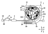
- a conventional winding device 101 described in Patent Document 1 is a device that winds one end side of a flat cable 102 and feeds the other end side thereof, and has a substantially cylindrical shape as a whole.
- one end side of the flat cable 102 introduced into the case 130 is inverted by one roller 106 ⁇ / b> A among the plurality of rollers 106 and held inside the inner annular wall 131. The other end is led out of the case 130. Then, the winding device 101 rotates the rotor 104 in the winding direction R by the urging force of the coil spring, so that the flat cable 102 is wound around the inner annular wall 131 and the flat cable is wound around the outer periphery of the plurality of rollers 106. 102 is wound, and thereby the flat cable 102 is wound.
- the rotor 104 rotates in the direction opposite to the winding direction R and is wound around the inner annular wall 131 and the outer periphery of the plurality of rollers 106.
- the winding of the flat cable 102 that has been removed is released, and the flat cable 102 is drawn out of the case 130.
- the inner flat cable 1021 may be wound linearly, and the outer flat cable 1023 may be loosely wound.
- the difference in length between the flat cable 1021 and the outer flat cable 1023 is caused, and the other end side of the wound portion of the inner flat cable 1021 is easily loosened due to the difference between the inner and outer circumferences.
- the slack portion 102A is caught in the winding device 101, which may cause the winding device 101 to malfunction.
- the slack interferes with other parts, which may cause the flat cable 102 to be damaged or disconnected.
- An object of the present invention is to provide a flat cable routing structure that prevents damage and disconnection of a flat cable and suppresses malfunction of a winding device even when a plurality of flat cables are used in an overlapping manner. It is in.
- the present invention according to claim 1 is a flat cable routing structure for supplying electric power to a slide body provided on a vehicle body floor, and is installed in the vicinity of the slide body and a plurality of flat cables stacked.
- a winding device that winds up one end side and feeds out the other end side, a separation position where the flat cable is drawn out and separated from the winding device, and the flat cable is wound up and close to the winding device
- a protector guided along the sliding direction of the slide body at the proximity position, and as the protector is slid from the separation position to the proximity position, the winding device is connected to the flat cable.
- a flat cable wiring structure characterized by comprising a slack-absorbing unit for absorbing the slack portion internally.
- each of the flat cables is folded in the width direction of the flat cable at two points spaced apart in the longitudinal direction.
- the slack absorbing portion is formed in a cylindrical shape and accommodates the intersecting portion inside, the dimension in the sliding direction is,
- the flat cable is formed so as to be larger than the dimension obtained by adding the difference between the inner and outer circumferences to the width dimension of the flat cable, and in the state where the protector is positioned at the proximity position, Is provided on the side of the separated position by the difference between the inner and outer circumferences of the outer flat cable.
- the present invention according to claim 3 is the flat cable routing structure according to claim 2, wherein at the both ends of the intersecting portion, overlapping portions are formed by overlapping the flat cables,
- the slack absorbing portion is provided with an overlapping storage chamber in which the overlapping portion is stored, and an intermediate storage chamber in which an intermediate portion other than the overlapping portion of the intersecting portion is stored.
- the dimension of the flat cable in the overlapping direction is smaller than the dimension of the overlapping accommodating chamber in the overlapping direction.
- a slack absorption part that absorbs the slack part consisting of the difference between the inner and outer circumferences of the inner flat cable inside, so the slack absorption part absorbs the slack part, and the slack part is closer to the winding device than the protector Don't make it happen. Therefore, the winding device can suppress malfunction of the winding device caused by winding of the slack portion and interference of the slack portion with other parts, and can prevent damage and disconnection of the flat cable.
- each flat cable intersects the longitudinal direction of the flat cable formed by being folded in the width direction of the flat cable at two positions spaced in the longitudinal direction.
- the slack absorbing portion is formed in a cylindrical shape and accommodates the intersecting portion inside, and the dimension in the sliding direction is larger than the dimension obtained by adding the inner and outer circumference differences to the width dimension of the flat cable. Therefore, when the protector is moved from the remote position to the close position, the force in the direction opposite to the force of the protector from the remote position to the close position (force from the close position to the close position) is generated.
- the inner flat cable will be moved to the separation position side by the inner and outer circumference difference than the outer flat cable, and the slack
- the structure yield portion absorbs the slack portion inside can be realized.
- overlapping portions are formed at both ends of the intersecting portion by overlapping the flat cables, and the slack absorbing portion includes an overlapping accommodating chamber in which the overlapping portion is accommodated. And an intermediate accommodating chamber in which an intermediate portion other than the overlapping portion of the intersecting portion is accommodated, and the intermediate accommodating chamber has a dimension in the overlapping direction of the flat cable smaller than a dimension in the overlapping direction of the overlapping accommodating chamber. Therefore, the movement in the overlapping direction of the intermediate portion other than the overlapping portion of the intersecting portion is restricted inside the protector, and the intermediate portion can be prevented from flapping or twisting in the overlapping direction.
- FIG. 4 is a perspective view illustrating a state where a flat cable is accommodated in the protector illustrated in FIG. 3. It is a perspective view which shows the state of the flat cable in the inside of a protector when the protector shown by FIG. 2 is located in a separation position.
- (A) is a perspective view which shows the state of the flat cable inside a protector when the protector shown in FIG. 2 is located in a proximity position
- (B) is a top view of (A).
- (A) is a plane which shows the conventional winding apparatus described in patent document 1
- (B) is a figure which expands and shows a part of (A).
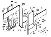
- a flat cable routing structure 1 is a structure for supplying electric power to an electronic device provided in a slide body S such as a slide seat or a slide door provided to be slidable in a vehicle longitudinal direction with respect to a vehicle in an automobile or the like. It is. As shown in FIGS. 1 and 2, the flat cable routing structure 1 is installed in the vicinity of a slide rail that slidably supports the slide body S, and a plurality of (three in the present embodiment) are stacked.
- a winding device 3 that winds up one end side 2A of the flat cable 2 and feeds out the other end side 2B, and a separation position where the flat cable 2 is fed out and separated from the winding device 3 (the position shown in FIG. 1A) ) And a proximity position (position shown in FIG. 1B) where the flat cable 2 is wound and close to the winding device 3, and the sliding direction of the slide body S (arrow Y direction). And a protector 4 to be configured.
- the slide rail extends in the front-rear direction of the vehicle, and the slide body S is installed so as to slide in the front-rear direction of the vehicle.
- the flat cable 2 is formed to be sufficiently longer than the slide distance of the slide sheet S, and its one end 2A is passed through the inside of the winding device 3 and then pulled out to be connected to the floor-side connector C1.
- the other end 2B is connected to the connector C2 on the slide sheet S side through the protector 4.
- the flat cable 2 has a flat strip-shaped conductor and an insulating coating that covers the conductor, and is formed into a thin strip having flexibility.
- the covering portion is made of a synthetic resin.
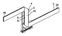
- the flat cable 2 is formed by being folded in the width direction of the flat cable 2 at two positions spaced in the longitudinal direction, and an orthogonal portion 20 orthogonal to the longitudinal direction of the flat cable 2.
- the inside of the protector 4 is formed in a crank shape having a (crossing portion), and the longitudinal ends of the orthogonal portion 20 are movable in the sliding direction (arrow Y direction) in a direction along the vertical direction (arrow X direction). Is housed in.
- the orthogonal portion 20 includes triangular portions 21 ⁇ / b> A and 21 ⁇ / b> B (overlapping portions) formed by folding the flat cable 2 positioned at both ends in the vertical direction (arrow X direction), and the orthogonal portion.
- 20 intermediate portions that is, a rectangular portion 22 (intermediate portion) located between the triangular portions 21A and 21B, and is configured in a parallelogram shape.
- Each of the triangular portions 21A and 21B has a right isosceles triangular shape in plan view, and two sides having the same length are provided along the vertical direction (arrow X direction) and the front-rear direction (arrow Y direction), respectively.
- the bottom side is provided with an inclination of 45 degrees with respect to the upper surface of the bottom wall 7 of the protector 4. Since the flat cable 2 is used in a state where three sheets are stacked, the triangular portions 21A and 21B have a thickness equivalent to six flat cables, and the rectangular portions 22 and the triangular portions 21A are formed. The one end 2A side and the other end 2B side of the triangular portion 21B are configured to have a thickness corresponding to three flat cables.
- an inner flat cable 21 is provided on the side close to the slide sheet S (the back side in the direction orthogonal to the paper surface in FIG. 1), and the side away from the slide sheet S (FIG. 1).
- An outer flat cable 2 2 is provided on the front side in the direction orthogonal to the inside of the drawing.
- the winding device 3 winds the flat cable 2 routed between a vehicle and a slide sheet (slide body S) that is slidably provided on a floor of the vehicle, for example, and the protector 4 moves closer. Accordingly, the flat cable 2 is wound up, and the flat cable 2 is unwound as the protector 4 moves away. It is used to prevent interference with S and the like.
- the winding device 3 includes a case 31 that accommodates the wound flat cable 2, a rotary table 32 that is rotatably provided in the case 31, and is rotatable on the rotary table 32. And a plurality of (six in this embodiment) rollers 33 and a spiral spring (not shown) for urging the rotary table 32 in the winding direction of the flat cable 2.
- the case 31 is provided with a central shaft 34, which pivotally supports the rotary table 32 so as to be rotatable at a substantially central portion thereof.
- the flat cable 2 is wound around the peripheral surface of the central shaft 34 on one end side 2 ⁇ / b> A of the flat cable 2, reversed by a reversing roller 33 ⁇ / b> A, and led out of the case 31.
- the rotary table 32 is rotated in the winding direction by the restoring force of the spiral spring, the flat cable 2 is wound around the outer periphery of the central shaft 34 and the outer periphery of the plurality of rollers 33 of the rotary table 32.
- the flat cable 2 is led out from this winding state, and the flat cable 2 is sent out from the outer periphery of the central shaft 34 to the outer periphery of the plurality of rollers 33, so that the flat cable 2 is sequentially fed out of the case 31. Yes.
- the sliding direction of the slide sheet S is indicated by an arrow Y
- the standing direction of the central shaft 34 is indicated by an arrow X
- the direction orthogonal to the arrows Y and X is indicated by an arrow Z.
- the arrow Y direction is the vehicle front-rear direction
- the arrow X direction is the vehicle vertical direction
- the arrow Z direction is the overlapping direction of the flat cables 2.
- the protector 4 has a first outlet 50 that opens upward and leads out the other end 2 ⁇ / b> B of the flat cable 2, and a protector 4 that opens backward and leads out one end 2 ⁇ / b> A of the flat cable 2.
- An L-shaped orthogonal accommodating portion 5 (slack absorbing portion) that accommodates the orthogonal portion 20 with two outlets 51, and a front-rear direction of the floor provided continuously below the orthogonal accommodating portion 5 And a sliding portion 6 that slides on a groove extending in the direction.
- the orthogonal accommodating portion 5 (protector 4) includes an L-shaped protector body 4A and an L-shaped cover 4B that holds the orthogonal portion 20 between the protector body 4A. It consists of members.
- the protector body 4A is integrally provided with a sliding portion 6.
- the cover 4B is integrally provided with an L-shaped locking claw 16 that is locked to the protector body 4A.
- the cover 4B is assembled to the protector body 4A by being slid downward with the locking claws 16 locked to the protector body 4A.
- the orthogonal accommodating portion 5 is provided so as to face the floor and has a rectangular plate-like bottom wall 7 whose longitudinal direction is provided along the vehicle front-rear direction, and an upper surface of the bottom wall 7.
- a pair of third wall portions 10A, 10B continuous to the rear side of each of the portions 8A, 8B, and the front side edges of the first wall portions 8A, 8B and the second wall portions 9A, 9B are overlapped with each other.
- one first wall portion 8A is provided on the inner side (the side closer to the slide sheet S in FIG. 1) in the overlapping direction (arrow Z direction), and the outer side in the overlapping direction ( The other first wall 8A is provided on the side far from the slide sheet S in FIG.
- the pair of first wall portions 8 ⁇ / b> A and 8 ⁇ / b> B includes a first storage chamber 80 that stores the triangular portion 21 ⁇ / b> A below the orthogonal portion 20 in the space between the pair of first wall portions 8 ⁇ / b> A and 8 ⁇ / b> B. (Overlapping storage chamber).
- the pair of first wall portions 8A and 8B are provided at an interval that is slightly larger than the thickness of the triangular portion 21A (in this embodiment, the thickness of six flat cables).
- an inner wall 81 is formed between the pair of first wall portions 8A and 8B so as to be inclined on the upper surface of the bottom wall 7 so as to contact the bottom side of the triangular portion 21A. .
- the inner wall 81 has one end provided continuously with the bottom wall 7 and the other end provided continuously with the first side wall 11A.
- the pair of second wall portions 9 ⁇ / b> A and 9 ⁇ / b> B is a second storage chamber 90 that stores the rectangular portion 22 of the orthogonal portion 20 in the space between the pair of second wall portions 9 ⁇ / b> A and 9 ⁇ / b> B. (Intermediate storage room).
- the pair of second wall portions 9A and 9B are provided at a distance so as to be slightly larger than the thickness of the rectangular portion 22 (thickness of three flat cables in this embodiment).
- the dimension in the overlapping direction (arrow Z direction) between the second wall portions 9A and 9B is formed to be smaller than the dimension in the overlapping direction between the pair of first wall portions 8A and 8B.
- the dimension of the second wall 9A in the sliding direction (the direction of the arrow Y) (the dimension between the first side wall 11A and the second side wall 12A) is the same as the dimension of the second wall 9B in the sliding direction (the first side wall 11B).
- the pair of third wall portions 10 ⁇ / b> A and 10 ⁇ / b> B is a third storage chamber that stores the rear side of the triangular portions 21 ⁇ / b> A and 21 ⁇ / b> B in the space between the pair of third wall portions 10 ⁇ / b> A and 10 ⁇ / b> B.
- the pair of third wall portions 10A and 10B are provided with a space slightly larger than the thickness of three flat cables) and overlap between the pair of third wall portions 10A and 10B.
- the dimension in the direction (arrow Z direction) is formed to be substantially equal to the dimension in the overlapping direction between the pair of second wall portions 9A and 9B.
- the gap between the pair of first wall portions 8A and 8B and the pair of second wall portions 9A and 9B is increased in the inner direction (the direction toward the inside of the orthogonal housing portion 5).
- a pair of first wall portions 8A and 8B and a pair of third wall portions 10A and 10B, and a pair of first wall portions 10A and 10B are arranged inward.
- a pair of second inclined portions 15 formed to be inclined in the direction (the direction toward the inside of the orthogonal accommodating portion 5) is provided.
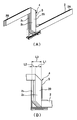
- the orthogonal accommodating portion 5 has a dimension L3 in the sliding direction (arrow Y direction) of the second wall portion 9A (“dimension in the sliding direction of the slack absorbing portion” in the claims).
- the width L1 of the flat cable 2 is slightly larger than the dimension obtained by adding the inner and outer circumference difference L2 between the outer flat cable 22 and the inner flat cable 21 generated when the winding device 3 winds the flat cable 2. It is formed to be large.
- the minimum inner width dimension L3 in the sliding direction (arrow Y direction) of the orthogonal housing portion 5 is formed to be slightly larger than the dimension obtained by adding the inner / outer circumference difference L2 to the width dimension L1 of the flat cable 2.
- absorbing the slack portion formed by the difference between the inner and outer circumferences of the outer flat cable and the inner flat cable means that the inner flat cable 21 is inside the orthogonal housing portion 5. This means that 2 2 is also moved relative to the separation position side by an inner / outer circumference difference L2 from the outer flat cable.
- one end side 2 ⁇ / b> A of the flat cable 2 is wired in advance in the winding device 3.
- the other end 2B of the flat cable 2 is folded in the width direction of the flat cable 2 to form a lower triangular portion 21A and a rectangular portion 22 and accommodated in the protector body 4A.
- the other end side 2B of the flat cable 2 is accommodated inside the L-shaped locking claw 16 of the cover 4B, and the cover 4B is attached.
- the locking claw 16 is locked to the second wall portion 9A of the protector body 4A, and the cover 4B is assembled to the protector body 4A.
- the triangular portion 21 ⁇ / b> A is accommodated in the first accommodating chamber 80, and the rectangular portion 22 is accommodated in the second accommodating chamber 90.
- the protector 4 is assembled.
- the flat cable 2 led out from the first lead-out port 50 is folded so as to form the upper triangular portion 21B, and the other end 2B of the flat cable 2 is connected to the connector C2 of the slide sheet S.
- one end 2A of the flat cable 2 led out from the second outlet 51 is connected to the floor connector C1. In this way, the flat cable routing structure 1 is assembled.
- the flat cable 2 which piled up three sheets was illustrated and demonstrated as the flat cable 2 piled up in multiple numbers, this invention is not limited to this,
- the flat cable 2 is two or more sheets. It only has to be stacked.
- the flat cable 2 includes one flat conductor, but the present invention is not limited to this, and the conductor may be composed of a plurality of core wires parallel to each other, and the core wire is a single wire. You may be comprised from.
- vertical part 20 of the flat cable 2 was provided orthogonally to the longitudinal direction of the flat cable 2, this invention is not limited to this.
- the orthogonal part 20 only needs to intersect the longitudinal direction of the flat cable 2, and the orthogonal accommodating part 5 (slack absorption part) may not be crank-shaped as long as the slack part can be absorbed therein. Is optional.
Landscapes
- Engineering & Computer Science (AREA)
- Mechanical Engineering (AREA)
- Electric Cable Arrangement Between Relatively Moving Parts (AREA)
- Protection Of Pipes Against Damage, Friction, And Corrosion (AREA)
Abstract
Priority Applications (2)
| Application Number | Priority Date | Filing Date | Title |
|---|---|---|---|
| CN201480035439.6A CN105393419B (zh) | 2013-04-23 | 2014-04-21 | 扁平电缆布设结构 |
| US14/786,289 US9701261B2 (en) | 2013-04-23 | 2014-04-21 | Flat cable routing structure |
Applications Claiming Priority (2)
| Application Number | Priority Date | Filing Date | Title |
|---|---|---|---|
| JP2013-090056 | 2013-04-23 | ||
| JP2013090056A JP6112660B2 (ja) | 2013-04-23 | 2013-04-23 | フラットケーブル配索構造 |
Publications (1)
| Publication Number | Publication Date |
|---|---|
| WO2014175204A1 true WO2014175204A1 (fr) | 2014-10-30 |
Family
ID=51791780
Family Applications (1)
| Application Number | Title | Priority Date | Filing Date |
|---|---|---|---|
| PCT/JP2014/061141 Ceased WO2014175204A1 (fr) | 2013-04-23 | 2014-04-21 | Structure d'acheminement de câble plat |
Country Status (4)
| Country | Link |
|---|---|
| US (1) | US9701261B2 (fr) |
| JP (1) | JP6112660B2 (fr) |
| CN (1) | CN105393419B (fr) |
| WO (1) | WO2014175204A1 (fr) |
Cited By (1)
| Publication number | Priority date | Publication date | Assignee | Title |
|---|---|---|---|---|
| US11273774B2 (en) * | 2018-06-26 | 2022-03-15 | Sumitomo Wiring Systems, Ltd. | Wire harness with short-long sides overlapping flat wires |
Families Citing this family (10)
| Publication number | Priority date | Publication date | Assignee | Title |
|---|---|---|---|---|
| JP6541034B2 (ja) * | 2015-12-22 | 2019-07-10 | 株式会社オートネットワーク技術研究所 | スライド配線装置 |
| JP6434931B2 (ja) * | 2016-04-06 | 2018-12-05 | 矢崎総業株式会社 | ケーブル配索構造 |
| JP6782686B2 (ja) * | 2017-12-11 | 2020-11-11 | 矢崎総業株式会社 | 回路体配索構造及び車両用回路体 |
| CN111902317B (zh) * | 2018-03-26 | 2023-10-31 | 古河电气工业株式会社 | 线缆卷绕装置以及滑动座椅用扁平线缆布置结构 |
| JP2020054097A (ja) * | 2018-09-26 | 2020-04-02 | 矢崎総業株式会社 | フラットケーブル巻取装置及びフラットケーブル配索構造 |
| JP2020078169A (ja) * | 2018-11-07 | 2020-05-21 | 矢崎総業株式会社 | 配索構造 |
| CN116525179A (zh) * | 2018-12-12 | 2023-08-01 | 株式会社自动网络技术研究所 | 布线构件及包装形态的布线构件 |
| JP2020114082A (ja) * | 2019-01-10 | 2020-07-27 | 矢崎総業株式会社 | シート用ワイヤハーネス |
| JP7147604B2 (ja) * | 2019-02-01 | 2022-10-05 | 株式会社オートネットワーク技術研究所 | 配線部材の配設構造 |
| JP2020141541A (ja) * | 2019-03-01 | 2020-09-03 | 株式会社タチエス | 給電経路付きの軸受構造 |
Citations (3)
| Publication number | Priority date | Publication date | Assignee | Title |
|---|---|---|---|---|
| JP2003032866A (ja) * | 2001-07-12 | 2003-01-31 | Yazaki Corp | フラットワイヤハーネスおよびその余長吸収装置 |
| JP2004312846A (ja) * | 2003-04-04 | 2004-11-04 | Fujikura Ltd | 電気接続構造、電気接続装置及びそれを用いたシート並びにハーネス余長吸収装置 |
| US20050133327A1 (en) * | 2003-12-22 | 2005-06-23 | Chih-Wei Kao | Automatic retractable device of flexible printed circuit board |
Family Cites Families (11)
| Publication number | Priority date | Publication date | Assignee | Title |
|---|---|---|---|---|
| US3300572A (en) * | 1963-12-18 | 1967-01-24 | Sanders Associates Inc | Extensible and retractable flexible circuit cable |
| US3433889A (en) * | 1966-06-30 | 1969-03-18 | Bell Telephone Labor Inc | Reciprocating electric connecting system |
| DE19839258A1 (de) * | 1998-08-28 | 2000-03-02 | Delphi Automotive Systems Gmbh | Elektrische Verbindung |
| JP2002058149A (ja) * | 2000-06-02 | 2002-02-22 | Yazaki Corp | ワイヤーハーネス余長吸収装置 |
| JP2002034139A (ja) * | 2000-07-17 | 2002-01-31 | Auto Network Gijutsu Kenkyusho:Kk | 回転接続装置 |
| JP4205516B2 (ja) | 2003-04-11 | 2009-01-07 | 古河電気工業株式会社 | フラットケーブル巻き取り繰り出し装置 |
| JP4180992B2 (ja) * | 2003-08-04 | 2008-11-12 | 矢崎総業株式会社 | 電線余長吸収装置 |
| JP4152414B2 (ja) * | 2006-02-09 | 2008-09-17 | 矢崎総業株式会社 | 回転コネクタ装置 |
| EP1981131A1 (fr) * | 2007-04-14 | 2008-10-15 | Delphi Technologies, Inc. | Dispositif de raccordement électrique |
| JP5101981B2 (ja) * | 2007-10-17 | 2012-12-19 | 矢崎総業株式会社 | リンク用ハーネス配索構造 |
| EP2383753A4 (fr) * | 2009-02-12 | 2014-06-18 | Fujikura Ltd | Faisceau de câbles pour dispositif électronique et dispositif électronique |
-
2013
- 2013-04-23 JP JP2013090056A patent/JP6112660B2/ja active Active
-
2014
- 2014-04-21 CN CN201480035439.6A patent/CN105393419B/zh active Active
- 2014-04-21 US US14/786,289 patent/US9701261B2/en active Active
- 2014-04-21 WO PCT/JP2014/061141 patent/WO2014175204A1/fr not_active Ceased
Patent Citations (3)
| Publication number | Priority date | Publication date | Assignee | Title |
|---|---|---|---|---|
| JP2003032866A (ja) * | 2001-07-12 | 2003-01-31 | Yazaki Corp | フラットワイヤハーネスおよびその余長吸収装置 |
| JP2004312846A (ja) * | 2003-04-04 | 2004-11-04 | Fujikura Ltd | 電気接続構造、電気接続装置及びそれを用いたシート並びにハーネス余長吸収装置 |
| US20050133327A1 (en) * | 2003-12-22 | 2005-06-23 | Chih-Wei Kao | Automatic retractable device of flexible printed circuit board |
Cited By (1)
| Publication number | Priority date | Publication date | Assignee | Title |
|---|---|---|---|---|
| US11273774B2 (en) * | 2018-06-26 | 2022-03-15 | Sumitomo Wiring Systems, Ltd. | Wire harness with short-long sides overlapping flat wires |
Also Published As
| Publication number | Publication date |
|---|---|
| CN105393419A (zh) | 2016-03-09 |
| CN105393419B (zh) | 2017-06-16 |
| JP6112660B2 (ja) | 2017-04-12 |
| JP2014217100A (ja) | 2014-11-17 |
| US9701261B2 (en) | 2017-07-11 |
| US20160059801A1 (en) | 2016-03-03 |
Similar Documents
| Publication | Publication Date | Title |
|---|---|---|
| JP6112660B2 (ja) | フラットケーブル配索構造 | |
| JP5896409B2 (ja) | フラットケーブル巻取装置 | |
| WO2010103904A1 (fr) | Dispositif d'alimentation en électricité | |
| EP2816693B1 (fr) | Dispositif d'enroulement de câble plat et procédé pour son assemblage | |
| JP6025205B2 (ja) | フラットケーブル巻取装置 | |
| EP2709223B1 (fr) | Structure d'acheminement de câble plat | |
| JP6434931B2 (ja) | ケーブル配索構造 | |
| JP5837335B2 (ja) | フラットケーブルの配索構造 | |
| JP5656933B2 (ja) | スライドシートのワイヤーハーネス配索構造 | |
| WO2015019829A1 (fr) | Support de maintien de câble | |
| JP2013151335A (ja) | フラットケーブルの巻取装置、及びフラットケーブルの配策構造 | |
| JP2008245392A (ja) | 電気接続構造 | |
| JP2016165993A (ja) | ワイヤハーネスの配索構造 | |
| JP5667129B2 (ja) | スライドシートのワイヤーハーネス配索構造 | |
| JP5847614B2 (ja) | フラットケーブル巻取装置 | |
| JP5467813B2 (ja) | スライドパネル用の給電装置 | |
| JP5342866B2 (ja) | 回転コネクタ装置 | |
| JP6285712B2 (ja) | フラットケーブル巻取装置 | |
| JP4101031B2 (ja) | 継電装置 | |
| JP2021083280A (ja) | フラットケーブル巻取装置及びフラットケーブル配索構造 |
Legal Events
| Date | Code | Title | Description |
|---|---|---|---|
| WWE | Wipo information: entry into national phase |
Ref document number: 201480035439.6 Country of ref document: CN |
|
| 121 | Ep: the epo has been informed by wipo that ep was designated in this application |
Ref document number: 14788275 Country of ref document: EP Kind code of ref document: A1 |
|
| WWE | Wipo information: entry into national phase |
Ref document number: 14786289 Country of ref document: US |
|
| NENP | Non-entry into the national phase |
Ref country code: DE |
|
| 122 | Ep: pct application non-entry in european phase |
Ref document number: 14788275 Country of ref document: EP Kind code of ref document: A1 |