WO2014175255A1 - Composé du magnésium contenant du fluor - Google Patents
Composé du magnésium contenant du fluor Download PDFInfo
- Publication number
- WO2014175255A1 WO2014175255A1 PCT/JP2014/061268 JP2014061268W WO2014175255A1 WO 2014175255 A1 WO2014175255 A1 WO 2014175255A1 JP 2014061268 W JP2014061268 W JP 2014061268W WO 2014175255 A1 WO2014175255 A1 WO 2014175255A1
- Authority
- WO
- WIPO (PCT)
- Prior art keywords
- positive electrode
- magnesium
- atom
- active material
- fluorine
- Prior art date
- Legal status (The legal status is an assumption and is not a legal conclusion. Google has not performed a legal analysis and makes no representation as to the accuracy of the status listed.)
- Ceased
Links
Images



Classifications
-
- C—CHEMISTRY; METALLURGY
- C01—INORGANIC CHEMISTRY
- C01B—NON-METALLIC ELEMENTS; COMPOUNDS THEREOF; METALLOIDS OR COMPOUNDS THEREOF NOT COVERED BY SUBCLASS C01C
- C01B25/00—Phosphorus; Compounds thereof
- C01B25/16—Oxyacids of phosphorus; Salts thereof
- C01B25/26—Phosphates
- C01B25/455—Phosphates containing halogen
-
- C—CHEMISTRY; METALLURGY
- C01—INORGANIC CHEMISTRY
- C01B—NON-METALLIC ELEMENTS; COMPOUNDS THEREOF; METALLOIDS OR COMPOUNDS THEREOF NOT COVERED BY SUBCLASS C01C
- C01B33/00—Silicon; Compounds thereof
- C01B33/20—Silicates
-
- H—ELECTRICITY
- H01—ELECTRIC ELEMENTS
- H01M—PROCESSES OR MEANS, e.g. BATTERIES, FOR THE DIRECT CONVERSION OF CHEMICAL ENERGY INTO ELECTRICAL ENERGY
- H01M10/00—Secondary cells; Manufacture thereof
- H01M10/05—Accumulators with non-aqueous electrolyte
- H01M10/054—Accumulators with insertion or intercalation of metals other than lithium, e.g. with magnesium or aluminium
-
- H—ELECTRICITY
- H01—ELECTRIC ELEMENTS
- H01M—PROCESSES OR MEANS, e.g. BATTERIES, FOR THE DIRECT CONVERSION OF CHEMICAL ENERGY INTO ELECTRICAL ENERGY
- H01M4/00—Electrodes
- H01M4/02—Electrodes composed of, or comprising, active material
- H01M4/36—Selection of substances as active materials, active masses, active liquids
- H01M4/58—Selection of substances as active materials, active masses, active liquids of inorganic compounds other than oxides or hydroxides, e.g. sulfides, selenides, tellurides, halogenides or LiCoFy; of polyanionic structures, e.g. phosphates, silicates or borates
- H01M4/5825—Oxygenated metallic salts or polyanionic structures, e.g. borates, phosphates, silicates, olivines
-
- C—CHEMISTRY; METALLURGY
- C01—INORGANIC CHEMISTRY
- C01P—INDEXING SCHEME RELATING TO STRUCTURAL AND PHYSICAL ASPECTS OF SOLID INORGANIC COMPOUNDS
- C01P2002/00—Crystal-structural characteristics
- C01P2002/70—Crystal-structural characteristics defined by measured X-ray, neutron or electron diffraction data
- C01P2002/72—Crystal-structural characteristics defined by measured X-ray, neutron or electron diffraction data by d-values or two theta-values, e.g. as X-ray diagram
-
- C—CHEMISTRY; METALLURGY
- C01—INORGANIC CHEMISTRY
- C01P—INDEXING SCHEME RELATING TO STRUCTURAL AND PHYSICAL ASPECTS OF SOLID INORGANIC COMPOUNDS
- C01P2002/00—Crystal-structural characteristics
- C01P2002/70—Crystal-structural characteristics defined by measured X-ray, neutron or electron diffraction data
- C01P2002/77—Crystal-structural characteristics defined by measured X-ray, neutron or electron diffraction data by unit-cell parameters, atom positions or structure diagrams
-
- C—CHEMISTRY; METALLURGY
- C01—INORGANIC CHEMISTRY
- C01P—INDEXING SCHEME RELATING TO STRUCTURAL AND PHYSICAL ASPECTS OF SOLID INORGANIC COMPOUNDS
- C01P2004/00—Particle morphology
- C01P2004/01—Particle morphology depicted by an image
- C01P2004/03—Particle morphology depicted by an image obtained by SEM
-
- C—CHEMISTRY; METALLURGY
- C01—INORGANIC CHEMISTRY
- C01P—INDEXING SCHEME RELATING TO STRUCTURAL AND PHYSICAL ASPECTS OF SOLID INORGANIC COMPOUNDS
- C01P2004/00—Particle morphology
- C01P2004/60—Particles characterised by their size
- C01P2004/62—Submicrometer sized, i.e. from 0.1-1 micrometer
-
- H—ELECTRICITY
- H01—ELECTRIC ELEMENTS
- H01M—PROCESSES OR MEANS, e.g. BATTERIES, FOR THE DIRECT CONVERSION OF CHEMICAL ENERGY INTO ELECTRICAL ENERGY
- H01M10/00—Secondary cells; Manufacture thereof
- H01M10/05—Accumulators with non-aqueous electrolyte
- H01M10/056—Accumulators with non-aqueous electrolyte characterised by the materials used as electrolytes, e.g. mixed inorganic/organic electrolytes
- H01M10/0564—Accumulators with non-aqueous electrolyte characterised by the materials used as electrolytes, e.g. mixed inorganic/organic electrolytes the electrolyte being constituted of organic materials only
- H01M10/0566—Liquid materials
-
- H—ELECTRICITY
- H01—ELECTRIC ELEMENTS
- H01M—PROCESSES OR MEANS, e.g. BATTERIES, FOR THE DIRECT CONVERSION OF CHEMICAL ENERGY INTO ELECTRICAL ENERGY
- H01M4/00—Electrodes
- H01M4/02—Electrodes composed of, or comprising, active material
- H01M4/36—Selection of substances as active materials, active masses, active liquids
- H01M4/58—Selection of substances as active materials, active masses, active liquids of inorganic compounds other than oxides or hydroxides, e.g. sulfides, selenides, tellurides, halogenides or LiCoFy; of polyanionic structures, e.g. phosphates, silicates or borates
-
- Y—GENERAL TAGGING OF NEW TECHNOLOGICAL DEVELOPMENTS; GENERAL TAGGING OF CROSS-SECTIONAL TECHNOLOGIES SPANNING OVER SEVERAL SECTIONS OF THE IPC; TECHNICAL SUBJECTS COVERED BY FORMER USPC CROSS-REFERENCE ART COLLECTIONS [XRACs] AND DIGESTS
- Y02—TECHNOLOGIES OR APPLICATIONS FOR MITIGATION OR ADAPTATION AGAINST CLIMATE CHANGE
- Y02E—REDUCTION OF GREENHOUSE GAS [GHG] EMISSIONS, RELATED TO ENERGY GENERATION, TRANSMISSION OR DISTRIBUTION
- Y02E60/00—Enabling technologies; Technologies with a potential or indirect contribution to GHG emissions mitigation
- Y02E60/10—Energy storage using batteries
Definitions
- the present invention relates to a fluorine-containing magnesium compound. More specifically, the present invention relates to a fluorine-containing polyanion compound that can be suitably used for a positive electrode active material of a magnesium ion secondary battery, a positive electrode active material using the compound, a positive electrode, and a magnesium ion secondary battery.
- Lithium ion secondary batteries are used in mobile phones, electric vehicles, stationary power supplies, and the like. However, it is difficult to mine or extract lithium used in the lithium ion secondary battery. The lithium ion secondary battery may generate heat due to overcharging. Furthermore, since miniaturization and high performance of devices are required, further miniaturization and high capacity of secondary batteries are desired.
- magnesium has a large energy capacity per unit volume.
- Magnesium is a richer resource than lithium and is easy to mine and extract. Furthermore, magnesium is safer and more practical than lithium and easy to handle. Therefore, as a secondary battery that replaces the lithium ion secondary battery, for example, a magnesium secondary battery including a negative electrode containing metal magnesium or a magnesium alloy as a negative electrode active material and a positive electrode containing manganese oxide as a positive electrode active material is proposed. (For example, see Patent Document 1).
- the positive electrode active material when manganese oxide is used as the positive electrode active material, the potential and energy density expected when using metal magnesium or a magnesium alloy as the negative electrode active material cannot be sufficiently ensured. Therefore, as a positive electrode active material used in a secondary battery including a negative electrode containing metal magnesium or a magnesium alloy as a negative electrode active material, magnesium ions can be reversibly inserted and desorbed, and a higher potential can be obtained during a redox reaction. In addition, a positive electrode active material that can ensure energy density and is more safe and practical is desired.
- the present invention has been made in view of the above-described prior art, and can reversibly insert and desorb magnesium ions, ensuring a higher potential and energy density in the oxidation-reduction reaction (charge / discharge reaction). It is an object of the present invention to provide a fluorine-containing magnesium compound, a positive electrode active material, a positive electrode, and a magnesium secondary battery, which can be more excellent in safety and practicality.
- the present invention (1) Formula (I): Mg m M n AO p F q (I) (In the formula, M represents a transition metal atom, tin atom, antimony atom or indium atom, A represents a phosphorus atom, silicon atom or sulfur atom, m is a number exceeding 0 and 2 or less, and n is 0.5 to 1) .5, p is 3 or 4, q is a number from 0.5 to 1.5)
- a fluorine-containing magnesium compound having a composition represented by: (2) In the X-ray diffraction pattern by powder X-ray diffraction, the diffraction angle represented by 2 ⁇ is in the range of 16.5 to 17.5 °, in the range of 20.5 to 21.5 °, and 24.5 to 25.
- the fluorine-containing magnesium compound according to (1) having a peak in a range of 5 °, a range of 26.2 to 27.2 °, a range of 29.3 to 30.3 °, and a range of 31 to 32 °, (3)
- the fluorine-containing magnesium compound according to (1) or (2) which has a monoclinic structure belonging to the space group C2 / c, (4)
- the fluorine-containing magnesium compound according to any one of (1) to (3) wherein (5) A positive electrode active material for a secondary battery comprising a negative electrode containing metal magnesium or a magnesium alloy as a negative electrode active material, A positive electrode active material comprising the fluorine-containing magnesium compound according to any one of (1) to (4), (6)
- magnesium ions can be reversibly inserted and desorbed, and a higher potential can be obtained during the oxidation-reduction reaction (charge / discharge reaction).
- the energy density can be ensured, and the excellent effect of being excellent in safety and practicality is exhibited.
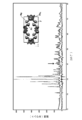
- FIG. 3 is an X-ray diffraction pattern of the raw material powder mixture obtained in Experimental Example 1 and the fired product obtained in Experimental Examples 2 to 6.
- 2 is an X-ray diffraction pattern of MgFePO 4 F obtained in Example 1.
- FIG. 3 is a drawing-substituting photograph showing an electron micrograph of MgFePO 4 F obtained in Example 1.
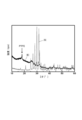
- FIG. 3 is an X-ray diffraction diagram of each of a positive electrode material obtained in Example 2 and MgFePO 4 F obtained in Example 1.
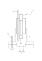
- FIG. FIG. 3 is a schematic explanatory diagram showing a configuration of a three-electrode cell used in Test Examples 1 and 2.
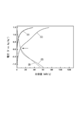
- Experiment 1 it is a graph of the charging / discharging curve which shows the result of having investigated the charging / discharging characteristic when the positive electrode material obtained in Example 2 was used.
- Test Example 1 it is a graph which shows the result of having investigated the relationship between each cycle when using the positive electrode material obtained in Example 2, and discharge capacity.
- 4 is an X-ray diffraction pattern of MgMnPO 4 F obtained in Example 3.
- FIG. 2 it is a graph of the charging / discharging curve which shows the result of having investigated the charging / discharging characteristic when the positive electrode material obtained in Example 4 was used.
- the fluorine-containing magnesium compound of the present invention has the formula (I): Mg m M n AO p F q (I) (In the formula, M represents a transition metal atom, tin atom, antimony atom or indium atom, A represents a phosphorus atom, silicon atom or sulfur atom, m is a number exceeding 0 and 2 or less, and n is 0.5 to 1) .5, p is 3 or 4, q is a number from 0.5 to 1.5)
- the fluorine-containing magnesium compound has a composition represented by the formula (I), it is possible to insert and desorb magnesium cations. In addition, even if a magnesium cation having a strong electrostatic interaction is inserted and removed, the fluorine-containing magnesium compound has a structure of the fluorine-containing magnesium compound (ie, AO 4 3 ⁇ or the like) and a fluorine anion. , The skeletal structure) can be stably maintained. In addition, since the fluorine-containing magnesium compound has the composition represented by the formula (I), the ionicity increases due to both strong covalent A—O interaction and the presence of fluorine atoms, and the operating voltage Can be synergistically improved.
- magnesium ions can be reversibly inserted (or retained) and desorbed, and a higher potential and energy density can be ensured during the oxidation-reduction reaction (charge / discharge reaction). In addition, an excellent effect of being excellent in safety and practicality is exhibited.
- M represents a transition metal atom, a tin atom, an antimony atom or an indium atom.
- the transition metal atom include a first transition metal atom such as a vanadium atom, a chromium atom, a manganese atom, an iron atom, a cobalt atom, a nickel atom, a copper atom, or a zinc atom. It is not limited to only.
- the M is preferably a first transition metal atom from the viewpoint of securing a higher potential and energy density during the oxidation-reduction reaction and obtaining a high weight energy density, and includes a vanadium atom, a manganese atom, an iron atom, A cobalt atom and a nickel atom are more preferable, and a manganese atom and an iron atom are further preferable.
- A represents a phosphorus atom, a silicon atom or a sulfur atom.
- a phosphorus atom is preferable from the viewpoints of securing a higher potential and energy density in the oxidation-reduction reaction and stability.
- m is a number exceeding 0 and 2 or less. m is 0.5 or more, preferably 1 or more from the viewpoint of securing the charge / discharge capacity, and is 2 or less, preferably 1.5 or less, from the viewpoint of securing the weight energy density.
- n is a number from 0.5 to 1.5.
- n is 0.5 or more, preferably 0.8 or more, from the viewpoint of securing the charge / discharge capacity, and 1.5 or less, preferably 1.2 or less, from the viewpoint of securing the weight energy density.
- p is 3 or 4.
- q is a number from 0.5 to 1.5.
- q is 0.5 or more, preferably 0.8 or more, from the viewpoint of securing the charge / discharge capacity, and is 1.5 or less, preferably 1.2 or less, from the viewpoint of securing the weight energy density.
- the ratio of m, n, o, p and q (m / n / o / p / q) is 1 from the viewpoint of securing a higher potential and energy density during the redox reaction. Any of / 1/1/4/1, 1/1/1/3/1 and 2/1/1/4/1 is preferable, and 1/1/1/4/1 is more preferable.
- the fluorine-containing magnesium compound has a diffraction angle represented by 2 ⁇ of 16.5 to 17.5 in an X-ray diffraction pattern by powder X-ray diffraction from the viewpoint of securing a higher potential and energy density in the oxidation-reduction reaction.
- ° range 20.5 to 21.5 ° range, 24.5 to 25.5 ° range, 26.2 to 27.2 ° range, 29.3 to 30.3 ° range and 31 to It preferably has a peak in the range of 32 °.
- the fluorine-containing magnesium compound preferably has a monoclinic structure belonging to the space group C2 / c.
- magnesium ions are likely to diffuse at a three-dimensional level in the crystal of the fluorine-containing magnesium compound. Therefore, according to the fluorine-containing magnesium compound, the charging reaction can be performed at high speed, and the charging time can be shortened.
- Examples of the fluorine-containing magnesium compound include formula (II): MgHAO 4 (II) (Wherein A is the same as above) And a magnesium oxoacid compound represented by formula (III): MC 2 O 4 ⁇ 2H 2 O (III) (Wherein M is the same as above)
- a mixture obtained by adding the oxalic acid transition metal compound represented by the above formula to a dispersion containing carbon nanotubes is kneaded by ball milling or the like, and the obtained kneaded product is fired at a firing temperature of 650 ° C. or more. Can be manufactured easily. Thus, since the mixture is kneaded by ball milling and then fired at a firing temperature of 650 ° C.
- a fluorine-containing magnesium compound that can be obtained can be obtained. From the viewpoint of obtaining a fluorine-containing magnesium compound capable of reversibly inserting and desorbing magnesium ions and ensuring a higher potential and energy density in the oxidation-reduction reaction (charge / discharge reaction).
- the temperature is preferably 650 ° C. or higher, more preferably 700 ° C. or higher, and still more preferably 800 ° C. or higher.
- the upper limit of a calcination temperature can be suitably determined in the range which can operate easily at the time of manufacture of a fluorine-containing magnesium compound.
- the fluorine-containing magnesium compound can be produced by a method such as a sol-gel method or a hydrothermal synthesis method, but the present invention is not limited only to such a method.
- the fluorine-containing magnesium compound having the composition represented by the formula (I) can reversibly insert and desorb magnesium ions.
- such a fluorine-containing magnesium compound can ensure a higher potential and energy density in the oxidation-reduction reaction (charge / discharge reaction). Therefore, it can use as a positive electrode active material which comprises the positive electrode of the magnesium secondary battery provided with the negative electrode containing metal magnesium or a magnesium alloy as a negative electrode active material.
- the fluorine-containing magnesium compound is excellent in safety and practicality.
- the fluorine-containing magnesium compound having the composition represented by the formula (I) is a positive electrode active material for a magnesium secondary battery, a positive electrode for a magnesium secondary battery, and a high-capacity magnesium secondary battery that is excellent in safety.
- the present invention includes such a positive electrode active material, a positive electrode, and a magnesium secondary battery.
- the positive electrode active material of the present invention is a positive electrode active material for a secondary battery provided with a negative electrode containing metal magnesium or a magnesium alloy as a negative electrode active material, and is characterized by comprising the fluorine-containing magnesium compound.
- the positive electrode of the present invention is a positive electrode for a secondary battery provided with a negative electrode containing metal magnesium or a magnesium alloy as a negative electrode active material, and is characterized by containing the positive electrode active material. Therefore, according to the positive electrode active material and the positive electrode, when used in a magnesium secondary battery, an excellent effect that a higher potential and energy density can be secured in the oxidation-reduction reaction (charge / discharge reaction) is achieved.
- the magnesium secondary battery of the present invention includes a positive electrode that reversibly inserts and releases magnesium cations, a negative electrode containing metal magnesium or a magnesium alloy as a negative electrode active material, an electrolyte, and a separator.
- the positive electrode containing the positive electrode active material which consists of the fluorine-containing magnesium compound of this invention mentioned above as a positive electrode is used for the magnesium secondary battery of this invention, in the charge / discharge reaction, higher electric potential and energy The density can be secured, and the excellent effect of being excellent in safety and practicality is exhibited.
- the positive electrode, the negative electrode, and the separator are arranged so that the positive electrode and the negative electrode are separated from each other by the separator, and are accommodated in the battery container, and the electrolytic solution is filled in the battery container. It can be manufactured by sealing the battery container body. Since the material, size, and shape of the battery container vary depending on the use of the magnesium secondary battery and the like, it is preferable to determine appropriately according to the use of the magnesium secondary battery and the like.
- the positive electrode is an electrode in which a current collector is loaded with a positive electrode material containing the positive electrode active material of the present invention as an active material.
- the positive electrode can be produced, for example, by applying the positive electrode material to a current collector.
- the positive electrode material contains the positive electrode active material of the present invention. Further, the positive electrode material may further contain a conductive additive and a binder as necessary. Examples of the conductive assistant include powders of carbon materials such as acetylene black, but the present invention is not limited to such examples. Since the content rate of the conductive auxiliary agent in the positive electrode material varies depending on the type of conductive auxiliary agent and the like, it is preferable to determine appropriately according to the type of conductive auxiliary agent.
- binder examples include fluororesins such as polytetrafluoroethylene, but the present invention is not limited to such examples.
- the positive electrode material contains a binder
- the content of the binder in the positive electrode material varies depending on the type of the binder and the like, and therefore can be appropriately determined according to the type of the binder. preferable.
- Examples of the material constituting the current collector include aluminum, platinum, molybdenum, and stainless steel, but the present invention is not limited to such examples.
- Examples of the shape of the current collector include a porous body, a foil, a plate, and a mesh made of fibers. However, the present invention is not limited to such examples.
- the amount of the positive electrode material applied to the current collector varies depending on the use of the magnesium secondary battery and the like, it is preferably determined as appropriate according to the use of the magnesium secondary battery and the like.
- the negative electrode is an electrode containing metallic magnesium or a magnesium alloy as a negative electrode active material.
- “magnesium alloy” refers to an alloy containing magnesium as a constituent element.
- the magnesium alloy include alloys containing magnesium and aluminum as constituent elements, alloys containing magnesium and zinc as constituent elements, alloys containing magnesium and manganese as constituent elements, and magnesium and bismuth as constituent elements. Alloys, alloys containing magnesium and nickel as constituent elements, alloys containing magnesium and antimony as constituent elements, alloys containing magnesium and tin as constituent elements, alloys containing magnesium and indium as constituent elements, magnesium and lead
- Such a negative electrode may be an electrode in which metal magnesium or a magnesium alloy is supported on a current collector, and an electrode obtained by molding metal magnesium or a magnesium alloy into a shape suitable for the electrode (for example, a plate shape). It may be.
- the separator may be made of a material that can separate the positive electrode and the negative electrode in the battery and can hold the electrolyte solution to ensure the ionic conductivity between the positive electrode and the negative electrode.
- the material include polyolefin resins such as polyethylene and polypropylene, fluororesins such as polytetrafluoroethylene, glass, and ceramics, but the present invention is not limited to such examples.
- the shape of the separator include a porous body, but the present invention is not limited to such examples.
- the electrolytic solution may be an electrolytic solution containing a magnesium cation.
- the electrolytic solution include a solution in which a magnesium salt is dissolved in a solvent, an ionic liquid composed of an inorganic material containing magnesium, and the like, but the present invention is not limited to such examples.
- the magnesium salt include magnesium halides such as magnesium chloride, magnesium bromide and magnesium iodide, magnesium inorganic salts such as magnesium perchlorate, magnesium tetrafluoroborate, magnesium hexafluorophosphate and magnesium hexafluoroarsenate.
- Magnesium organic salt compounds such as bis (trifluoromethylsulfonyl) imido magnesium, magnesium benzoate, magnesium salicylate, magnesium phthalate, magnesium acetate, magnesium propionate, Grignard reagent, etc. It is not limited to only.
- the solvent examples include carbonate compounds such as propylene carbonate, ethylene carbonate, dimethol carbonate, ethylmethyl carbonate, and diethyl carbonate; lactone compounds such as ⁇ -butyrolactone and ⁇ -valerolactone; tetrahydrofuran, 2-methyltetrahydrofuran, dimethoxy
- carbonate compounds such as propylene carbonate, ethylene carbonate, dimethol carbonate, ethylmethyl carbonate, and diethyl carbonate
- lactone compounds such as ⁇ -butyrolactone and ⁇ -valerolactone
- tetrahydrofuran 2-methyltetrahydrofuran
- dimethoxy examples include ether compounds such as ethane; acetonitrile and the like, but the present invention is not limited to such examples.
- the fluorine-containing magnesium compound having the composition represented by the formula (I) is used in the positive electrode active material, the positive electrode, and the magnesium secondary battery of the present invention, an oxidation-reduction reaction (charge / discharge reaction) ), A higher potential and energy density can be ensured, and the safety and practicality are excellent. Therefore, the positive electrode active material, the positive electrode, and the magnesium secondary battery of the present invention can be suitably used for, for example, a device that is required to be downsized and high performance.
- the obtained mixture was put into a chrome copper container together with zirconia balls and mixed for 24 hours at 400 rpm using a planetary ball mill to obtain a raw material powder mixture (Experimental Example 1). Thereafter, the obtained raw material powder mixture was formed into pellets, and was placed in an argon gas atmosphere at 500 ° C. (Experimental Example 2), 650 ° C. (Experimental Example 3), 700 ° C. (Experimental Example 4), 750 ° C. (Experimental Example 5) or Firing was carried out at a firing temperature of 800 ° C. (Experimental Example 6) for 5 hours.
- X-ray diffraction of the raw material powder mixture (Experiment 1) and the fired products obtained in Experiments 2 to 6 was examined.
- X-ray diffraction was measured using an X-ray diffraction measuring apparatus (trade name: RINT2200, manufactured by Rigaku Corporation) using CuK ⁇ monochromatized with a monochromator as an X-ray source.
- the measurement conditions of X-ray diffraction were tube voltage: 40 kV, tube current: 40 mA, scanning speed: 0.02 ° / min and scanning time: 2 seconds for Experimental Examples 1 to 5, scanning speed: For Experimental Example 6. 0.02 ° / min and scanning time: 15 seconds.
- the X-ray diffraction patterns of the raw material powder mixture obtained in Experimental Example 1 and the fired products obtained in Experimental Examples 2 to 6 are shown in FIG.
- Example 1 By performing the following operations, the formula (I): Mg m M n AO p F q (I) (In the formula, M represents a transition metal atom, tin atom, antimony atom or indium atom, A represents a phosphorus atom, silicon atom or sulfur atom, m is a number exceeding 0 and 2 or less, and n is 0.5 to 1) .5, p is 3 or 4, q is a number from 0.5 to 1.5) MgFePO 4 F, which is an example of a fluorine-containing magnesium compound having a composition represented by:
- magnesium hydrogen phosphate (MgHPO 4 ), ammonium fluoride (NH 4 F), and iron (II) oxalate dihydrate (FeC 2 O 4 .2H 2 O) were mixed with MgHPO 4 / NH 4.
- F / FeC 2 O 4 ⁇ 2H 2 O ( molar ratio) was mixed so that the 1/1/1.
- an ethanol dispersion of carbon nanotubes carbon nanotube concentration: 2.5 g / L
- the obtained mixture was put together with zirconia balls into a chromium copper container, and mixed at 400 rpm for 24 hours using a planetary ball mill to obtain a raw material powder mixture.
- the obtained raw material powder mixture was pellet-molded and fired at 800 ° C. for 5 hours in an argon gas atmosphere to obtain MgFePO 4 F.
- the crystal phase of the obtained MgFePO 4 F was examined by a powder X-ray diffraction method.
- Powder X-ray diffraction was measured using an X-ray diffractometer (trade name: RINT2200, manufactured by Rigaku Corporation) using CuK ⁇ rays having a wavelength of 0.15418 nm as an X-ray source.
- the measurement conditions for powder X-ray diffraction were tube voltage: 40 kV and tube current: 40 mA.
- the X-ray diffraction pattern of MgFePO 4 F obtained in Example 1 is shown in FIG.
- the obtained MgFePO 4 F crystal has a diffraction angle represented by 2 ⁇ in the range of 16.5 to 17.5 ° in the X-ray diffraction pattern by powder X-ray diffraction, In the range of 5 to 21.5 °, in the range of 24.5 to 25.5 °, in the range of 26.2 to 27.2 °, in the range of 29.3 to 30.3 ° and in the range of 31 to 32 ° It turns out that it has a peak.
- the elemental composition of the crystal was examined by Rietveld analysis, it was confirmed to be MgFePO 4 F 0.91 .
- MgFePO 4 F was observed with a scanning electron microscope.
- An electron micrograph of MgFePO 4 F obtained in Example 1 is shown in FIG. In the figure, the scale bar indicates 0.5 ⁇ m.
- Example 2 MgFePO 4 F obtained in Example 1 as a positive electrode active material, acetylene black (trade name: Denka Black, manufactured by Denki Kagaku Kogyo Co., Ltd.) as a conductive auxiliary agent, and polytetrafluoroethylene (PTFE) (as a binder) Made of Mitsui-DuPont Fluorochemical Co., Ltd., trade name: PTFE 6-J) and chrome copper container together with zirconia balls so that MgFePO 4 F / acetylene black / PTFE (mass ratio) is 50/40/10
- the mixture obtained was mixed at 400 rpm for 6 hours using a planetary ball mill to obtain a positive electrode material.
- Example 2 The X-ray diffraction of each of the positive electrode material obtained in Example 2 and MgFePO 4 F obtained in Example 1 was examined.
- X-ray diffraction was measured using an X-ray diffraction measuring apparatus (trade name: RINT2200, manufactured by Rigaku Corporation) using CuK ⁇ monochromatized with a monochromator as an X-ray source.
- the X-ray diffraction measurement conditions were tube voltage: 40 kV and tube current: 40 mA.
- the X-ray diffraction patterns of the positive electrode material obtained in Example 2 and the MgFePO 4 F obtained in Example 1 are shown in FIG.
- the X-ray diffraction pattern of (A) is the X-ray diffraction pattern of MgFePO 4 F obtained in Example 1
- the X-ray diffraction pattern of (B) is the X-ray diffraction of the positive electrode material obtained in Example 2. It is a pattern.
- Test example 1 In a glove box maintained in an argon gas atmosphere, the positive electrode material obtained in Example 2 was punched into a disc shape (diameter 6 mm, thickness about 0.1 mm). The obtained disc-shaped positive electrode material was sandwiched between platinum meshes 11b (manufactured by Niraco, trade name: platinum net) to obtain a positive electrode material 11a. A positive electrode material 11a was disposed on a platinum plate 11b as a current collector to obtain a working electrode 11. Next, the working electrode 11 obtained, the counter electrode 12 made of a magnesium rod, the reference electrode 13 made of an Ag + / Ag electrode, and the electrolyte solution 14 obtained in Production Example 1 were used, as shown in FIG. A three-electrode cell 1 was constructed.
- a charge / discharge test was performed using the obtained three-electrode cell 1 and a multi-channel charge / discharge device (trade name: HD1001-SM8, manufactured by Hokuto Denko Co., Ltd.). The charge / discharge test was performed at a discharge rate of 1/30 C while keeping the cell at room temperature.
- the upper limit potential of the potential range of charge and discharge was 1.5V vs Ag + / Ag, the lower limit electric potential and -1.1V vs Ag + / Ag.
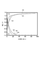
- Test Example 1 the results of examining the charge / discharge characteristics when using the positive electrode material obtained in Example 2 are shown in FIG.
- (A) is a charging curve when the first charging is performed
- (B) is a discharging curve when the first discharging is performed
- (C) is a charging curve when the second charging is performed
- (D) shows a discharge curve when the second discharge is performed.
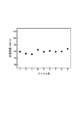
- the result of investigating the relationship between each cycle and the discharge capacity when using the positive electrode material obtained in Example 2 is shown in FIG.
- Example 3 By performing the following operations, MgMnPO 4 F, which is an example of a fluorine-containing magnesium compound having a composition represented by the formula (I), was prepared.
- magnesium hydrogen phosphate (MgHPO 4 ), ammonium fluoride (NH 4 F), manganese oxalate dihydrate (MnC 2 O 4 .2H 2 O), MgHPO 4 / NH 4 F / MnC 2 O 4 ⁇ 2H 2 O ( molar ratio) was mixed so that the 1/1/1.
- an ethanol dispersion of carbon nanotubes carbon nanotube concentration: 2.5 g / L
- the obtained mixture was put together with zirconia balls into a chromium copper container, and mixed at 400 rpm for 24 hours using a planetary ball mill to obtain a raw material powder mixture.
- the obtained raw material powder mixture was pellet-molded and fired at 800 ° C. for 5 hours in an argon gas atmosphere to obtain MgMnPO 4 F.
- the crystal phase of the obtained MgMnPO 4 F was examined by a powder X-ray diffraction method.
- Powder X-ray diffraction was measured using an X-ray diffractometer (trade name: RINT2200, manufactured by Rigaku Corporation) using CuK ⁇ rays having a wavelength of 0.15418 nm as an X-ray source.
- the measurement conditions for powder X-ray diffraction were tube voltage: 40 kV and tube current: 40 mA.
- the X-ray diffraction pattern of MgMnPO 4 F obtained in Example 3 is shown in FIG.
- the obtained MgMnPO 4 F crystal has an X-ray diffraction pattern by powder X-ray diffraction in which the diffraction angle represented by 2 ⁇ is in the range of 16.5 to 17.5 °, 20 In the range of 5 to 21.5 °, in the range of 24.5 to 25.5 °, in the range of 26.2 to 27.2 °, in the range of 29.3 to 30.3 ° and in the range of 31 to 32 ° It turns out that it has a peak.
- Example 4 A positive electrode material was obtained in the same manner as in Example 2 except that MgMnPO 4 F obtained in Example 3 was used instead of MgFePO 4 F obtained in Example 1 as the positive electrode active material. .
- Test example 2 In Test Example 1, a positive electrode material obtained in Example 4 was used instead of the positive electrode material obtained in Example 2, and the same operation as in Test Example 1 was performed to construct a three-electrode cell. did.
- a charge / discharge test was performed using the obtained three-electrode cell and multi-channel charge / discharge device (trade name: HD1001-SM8, manufactured by Hokuto Denko Co., Ltd.). The charge / discharge test was performed at a discharge rate of 1/50 C while maintaining the cell temperature at 55 ° C. in a thermostatic bath.
- the upper limit potential of the potential range of charge and discharge was 1.5V vs Ag + / Ag, the lower limit electric potential and -1.1V vs Ag + / Ag.
- Test Example 2 the results of examining the charge / discharge characteristics when the positive electrode material obtained in Example 4 was used are shown in FIG.
- (A1) is a charging curve when the first charging is performed
- (B1) is a discharging curve when the first discharging is performed
- (A2) is a charging curve when the second charging is performed.
- (B1) is a discharge curve when the second discharge is performed
- (A3) is a charge curve when the third charge is performed
- B3) is a discharge curve when the third discharge is performed
- A4) shows a charging curve when the fourth charging is performed
- (B4) shows a discharging curve when the fourth discharging is performed.
- Example 5 Test example except that a fluorine-containing magnesium compound having a composition represented by the formula (I) other than MgFePO 4 F obtained in Example 1 and MgMnPO 4 F obtained in Example 3 was used as the positive electrode active material The same operation as 2 is performed to construct a three-electrode cell. Next, using the obtained three-electrode cell, the same operation as in Test Example 2 is performed, and the charge / discharge characteristics are examined. As a result, the same charge / discharge characteristics as those of the three-electrode cell having MgFePO 4 F obtained in Example 1 and MgMnPO 4 F obtained in Example 3 are observed as the positive electrode active material.
- a fluorine-containing magnesium compound having a composition represented by the formula (I) other than MgFePO 4 F obtained in Example 1 and MgMnPO 4 F obtained in Example 3 was used as the positive electrode active material
- the same operation as 2 is performed to construct a three-electrode cell.
- the same operation as in Test Example 2
- magnesium ions can be reversibly desorbed and inserted, and high potential and high capacity can be secured. Recognize. Therefore, according to the fluorine-containing magnesium compound, a magnesium ion secondary battery having a high potential, a high capacity, a high energy density, and excellent safety and practicality as compared with a conventional lithium secondary battery or the like. It is suggested that it is possible to provide
Landscapes
- Chemical & Material Sciences (AREA)
- Organic Chemistry (AREA)
- Engineering & Computer Science (AREA)
- Inorganic Chemistry (AREA)
- Materials Engineering (AREA)
- Chemical Kinetics & Catalysis (AREA)
- Electrochemistry (AREA)
- General Chemical & Material Sciences (AREA)
- Manufacturing & Machinery (AREA)
- Crystallography & Structural Chemistry (AREA)
- Battery Electrode And Active Subsutance (AREA)
- Secondary Cells (AREA)
Abstract
L'invention porte sur un composé du magnésium contenant du fluer, ayant une composition exprimée par la formule: MgmMnAOpFq (dans la formule, M représente un atome d'un métal de transition, un atome d'étain, un atome d'antimoine ou un atome d'indium ; A représente un atome de phosphore, un atome de silicium ou un atome de soufre ; m représente un nombre supérieur à 0 et inférieur ou égal à 2 ; n représente un nombre de 0,5 à 1,5 ; p représente 3 ou 4 ; et q représente un nombre de 0,5 à 1,5) ; sur un matériau actif d'électrode positive fabriquée en ce composé ; sur une électrode positive contenant ce matériau actif ; et sur une batterie secondaire au magnésium pourvue de cette électrode positive.
Applications Claiming Priority (2)
| Application Number | Priority Date | Filing Date | Title |
|---|---|---|---|
| JP2013-091370 | 2013-04-24 | ||
| JP2013091370A JP2014214040A (ja) | 2013-04-24 | 2013-04-24 | フッ素含有マグネシウム化合物 |
Publications (1)
| Publication Number | Publication Date |
|---|---|
| WO2014175255A1 true WO2014175255A1 (fr) | 2014-10-30 |
Family
ID=51791827
Family Applications (1)
| Application Number | Title | Priority Date | Filing Date |
|---|---|---|---|
| PCT/JP2014/061268 Ceased WO2014175255A1 (fr) | 2013-04-24 | 2014-04-22 | Composé du magnésium contenant du fluor |
Country Status (2)
| Country | Link |
|---|---|
| JP (1) | JP2014214040A (fr) |
| WO (1) | WO2014175255A1 (fr) |
Cited By (2)
| Publication number | Priority date | Publication date | Assignee | Title |
|---|---|---|---|---|
| US11133526B2 (en) | 2016-12-07 | 2021-09-28 | Panasonic Intellectual Property Management Co., Ltd. | Solid electrolyte having magnesium ion conductivity and magnesium secondary battery using the same |
| US11349154B2 (en) | 2016-12-07 | 2022-05-31 | Panasonic Intellectual Property Management Co., Ltd. | Secondary battery using alkaline earth metal ion moving during charge and discharge |
Citations (4)
| Publication number | Priority date | Publication date | Assignee | Title |
|---|---|---|---|---|
| JP2009064731A (ja) * | 2007-09-07 | 2009-03-26 | Sony Corp | 正極活物質及びその製造方法、並びに電気化学デバイス |
| JP2009517490A (ja) * | 2005-11-25 | 2009-04-30 | シクパ・ホールディング・ソシエテ・アノニム | 赤外線吸収凹版インク |
| WO2012122080A1 (fr) * | 2011-03-08 | 2012-09-13 | Pellion Technologies Inc. | Composants de pile rechargeable au magnésium-ion et ensemble associé |
| WO2014017461A1 (fr) * | 2012-07-25 | 2014-01-30 | 国立大学法人京都大学 | Composé au magnésium, procédé de fabrication de celui-ci, matériau actif d'électrode positive, électrode positive, et batterie secondaire au magnésium-ion |
-
2013
- 2013-04-24 JP JP2013091370A patent/JP2014214040A/ja active Pending
-
2014
- 2014-04-22 WO PCT/JP2014/061268 patent/WO2014175255A1/fr not_active Ceased
Patent Citations (4)
| Publication number | Priority date | Publication date | Assignee | Title |
|---|---|---|---|---|
| JP2009517490A (ja) * | 2005-11-25 | 2009-04-30 | シクパ・ホールディング・ソシエテ・アノニム | 赤外線吸収凹版インク |
| JP2009064731A (ja) * | 2007-09-07 | 2009-03-26 | Sony Corp | 正極活物質及びその製造方法、並びに電気化学デバイス |
| WO2012122080A1 (fr) * | 2011-03-08 | 2012-09-13 | Pellion Technologies Inc. | Composants de pile rechargeable au magnésium-ion et ensemble associé |
| WO2014017461A1 (fr) * | 2012-07-25 | 2014-01-30 | 国立大学法人京都大学 | Composé au magnésium, procédé de fabrication de celui-ci, matériau actif d'électrode positive, électrode positive, et batterie secondaire au magnésium-ion |
Non-Patent Citations (1)
| Title |
|---|
| WA: "Kagaku Daijiten 9 Mimumemoyayuyorarirurerowa", ENCYCLOPAEDIA CHIMICA, 31 July 1962 (1962-07-31), MASAO NANJO, pages 1015 * |
Cited By (2)
| Publication number | Priority date | Publication date | Assignee | Title |
|---|---|---|---|---|
| US11133526B2 (en) | 2016-12-07 | 2021-09-28 | Panasonic Intellectual Property Management Co., Ltd. | Solid electrolyte having magnesium ion conductivity and magnesium secondary battery using the same |
| US11349154B2 (en) | 2016-12-07 | 2022-05-31 | Panasonic Intellectual Property Management Co., Ltd. | Secondary battery using alkaline earth metal ion moving during charge and discharge |
Also Published As
| Publication number | Publication date |
|---|---|
| JP2014214040A (ja) | 2014-11-17 |
Similar Documents
| Publication | Publication Date | Title |
|---|---|---|
| Lan et al. | Metallic silver doped vanadium pentoxide cathode for aqueous rechargeable zinc ion batteries | |
| Zhang et al. | A facile strategy for the synthesis of three-dimensional heterostructure self-assembled MoSe 2 nanosheets and their application as an anode for high-energy lithium-ion hybrid capacitors | |
| Wei et al. | POM-based metal-organic framework/reduced graphene oxide nanocomposites with hybrid behavior of battery-supercapacitor for superior lithium storage | |
| Alfaruqi et al. | Enhanced reversible divalent zinc storage in a structurally stable α-MnO2 nanorod electrode | |
| Lin et al. | Advanced electrochemical performance of Li4Ti5O12-based materials for lithium-ion battery: synergistic effect of doping and compositing | |
| Hu et al. | Pyrite FeS 2 for high-rate and long-life rechargeable sodium batteries | |
| Peng et al. | Ultrathin δ-MnO 2 nanoflakes with Na+ intercalation as a high-capacity cathode for aqueous zinc-ion batteries | |
| Rasul et al. | Synthesis and electrochemical behavior of hollandite MnO2/acetylene black composite cathode for secondary Mg-ion batteries | |
| Marino et al. | Nanoconfined phosphorus in mesoporous carbon as an electrode for Li-ion batteries: performance and mechanism | |
| Patil et al. | High capacity MoO 3/rGO nanocomposite anode for lithium ion batteries: an intuition into the conversion mechanism of MoO 3 | |
| Zhang et al. | Effect of Ti-doping on the electrochemical performance of sodium vanadium (III) phosphate | |
| Kisu et al. | The origin of anomalous large reversible capacity for SnO 2 conversion reaction | |
| Shaji et al. | Tin selenide/N-doped carbon composite as a conversion and alloying type anode for sodium-ion batteries | |
| Yan et al. | A novel pineapple-structured Si/TiO2 composite as anode material for lithium ion batteries | |
| Kollu et al. | A high capacity MnFe 2 O 4/rGO nanocomposite for Li and Na-ion battery applications | |
| WO2017099137A1 (fr) | Matériau actif d'électrode positive pour pile rechargeable potassium-ion | |
| Yan et al. | Entrapment of polysulfides by Al2O3 modified separator for high energy Li–S redox flow batteries | |
| Chae et al. | Highly reversible conversion-capacity of MnO x-loaded ordered mesoporous carbon nanorods for lithium-ion battery anodes | |
| JP5699876B2 (ja) | ナトリウムイオン電池用活物質およびナトリウムイオン電池 | |
| WO2014030500A1 (fr) | Corps d'électrode et cellule le comprenant | |
| Choi et al. | Zinc doped H2Ti12O25 anode and activated carbon cathode for hybrid supercapacitor with superior performance | |
| Pramudita et al. | Using in situ synchrotron x-ray diffraction to study lithium-and sodium-ion batteries: A case study with an unconventional battery electrode (Gd2TiO5) | |
| Liu et al. | Fe-modified NASICON-type Na 3 V 2 (PO 4) 3 as a cathode material for sodium ion batteries | |
| Tang et al. | High performance of phosphorus and fluorine co-doped nickel-rich cathode material for lithium ion batteries | |
| JPWO2014168218A1 (ja) | 多価金属二次電池 |
Legal Events
| Date | Code | Title | Description |
|---|---|---|---|
| 121 | Ep: the epo has been informed by wipo that ep was designated in this application |
Ref document number: 14788117 Country of ref document: EP Kind code of ref document: A1 |
|
| DPE1 | Request for preliminary examination filed after expiration of 19th month from priority date (pct application filed from 20040101) | ||
| NENP | Non-entry into the national phase |
Ref country code: DE |
|
| 122 | Ep: pct application non-entry in european phase |
Ref document number: 14788117 Country of ref document: EP Kind code of ref document: A1 |