WO2014175396A1 - Foret et procédé permettant de fabriquer un produit coupé à l'aide de ce dernier - Google Patents
Foret et procédé permettant de fabriquer un produit coupé à l'aide de ce dernier Download PDFInfo
- Publication number
- WO2014175396A1 WO2014175396A1 PCT/JP2014/061610 JP2014061610W WO2014175396A1 WO 2014175396 A1 WO2014175396 A1 WO 2014175396A1 JP 2014061610 W JP2014061610 W JP 2014061610W WO 2014175396 A1 WO2014175396 A1 WO 2014175396A1
- Authority
- WO
- WIPO (PCT)
- Prior art keywords
- pair
- drill
- chisel
- edges
- region
- Prior art date
- Legal status (The legal status is an assumption and is not a legal conclusion. Google has not performed a legal analysis and makes no representation as to the accuracy of the status listed.)
- Ceased
Links
Images






Classifications
-
- B—PERFORMING OPERATIONS; TRANSPORTING
- B23—MACHINE TOOLS; METAL-WORKING NOT OTHERWISE PROVIDED FOR
- B23B—TURNING; BORING
- B23B51/00—Tools for drilling machines
- B23B51/02—Twist drills
-
- B—PERFORMING OPERATIONS; TRANSPORTING
- B23—MACHINE TOOLS; METAL-WORKING NOT OTHERWISE PROVIDED FOR
- B23B—TURNING; BORING
- B23B2251/00—Details of tools for drilling machines
- B23B2251/04—Angles, e.g. cutting angles
- B23B2251/043—Helix angles
- B23B2251/046—Variable
-
- B—PERFORMING OPERATIONS; TRANSPORTING
- B23—MACHINE TOOLS; METAL-WORKING NOT OTHERWISE PROVIDED FOR
- B23B—TURNING; BORING
- B23B2251/00—Details of tools for drilling machines
- B23B2251/08—Side or plan views of cutting edges
- B23B2251/085—Discontinuous or interrupted cutting edges
-
- B—PERFORMING OPERATIONS; TRANSPORTING
- B23—MACHINE TOOLS; METAL-WORKING NOT OTHERWISE PROVIDED FOR
- B23B—TURNING; BORING
- B23B2251/00—Details of tools for drilling machines
- B23B2251/14—Configuration of the cutting part, i.e. the main cutting edges
-
- B—PERFORMING OPERATIONS; TRANSPORTING
- B23—MACHINE TOOLS; METAL-WORKING NOT OTHERWISE PROVIDED FOR
- B23B—TURNING; BORING
- B23B2251/00—Details of tools for drilling machines
- B23B2251/18—Configuration of the drill point
-
- B—PERFORMING OPERATIONS; TRANSPORTING
- B23—MACHINE TOOLS; METAL-WORKING NOT OTHERWISE PROVIDED FOR
- B23B—TURNING; BORING
- B23B2251/00—Details of tools for drilling machines
- B23B2251/40—Flutes, i.e. chip conveying grooves
- B23B2251/408—Spiral grooves
-
- B—PERFORMING OPERATIONS; TRANSPORTING
- B23—MACHINE TOOLS; METAL-WORKING NOT OTHERWISE PROVIDED FOR
- B23B—TURNING; BORING
- B23B2251/00—Details of tools for drilling machines
- B23B2251/50—Drilling tools comprising cutting inserts
-
- B—PERFORMING OPERATIONS; TRANSPORTING
- B23—MACHINE TOOLS; METAL-WORKING NOT OTHERWISE PROVIDED FOR
- B23B—TURNING; BORING
- B23B2251/00—Details of tools for drilling machines
- B23B2251/70—Drills with vibration suppressing means
-
- Y—GENERAL TAGGING OF NEW TECHNOLOGICAL DEVELOPMENTS; GENERAL TAGGING OF CROSS-SECTIONAL TECHNOLOGIES SPANNING OVER SEVERAL SECTIONS OF THE IPC; TECHNICAL SUBJECTS COVERED BY FORMER USPC CROSS-REFERENCE ART COLLECTIONS [XRACs] AND DIGESTS
- Y10—TECHNICAL SUBJECTS COVERED BY FORMER USPC
- Y10T—TECHNICAL SUBJECTS COVERED BY FORMER US CLASSIFICATION
- Y10T408/00—Cutting by use of rotating axially moving tool
- Y10T408/89—Tool or Tool with support
- Y10T408/909—Having peripherally spaced cutting edges
- Y10T408/9095—Having peripherally spaced cutting edges with axially extending relief channel
- Y10T408/9097—Spiral channel
Definitions
- the present invention relates to a drill used for cutting and a method for manufacturing a cut product.
- Patent Document 1 a drill described in Japanese Patent Application Laid-Open No. 2004-34220 (Patent Document 1) is known as a drill used for cutting a work material such as a metal member.
- the drill described in Patent Document 1 has a second cutting edge that functions as a thinning blade by removing a part of the chisel edge that smoothly connects to the main cutting edge by X thinning. According to this, since the cutting speed of the main cutting edge is higher than that of the chisel edge including the thinning blade, the chips generated at the chisel edge at the time of cutting are pulled by the chips generated by the main cutting edge. Therefore, cracks are generated in the chips generated at the chisel edge, so that the chips can be finely divided.
- the present invention has been made in view of the above problems, and an object of the present invention is to provide a drill that can sever chips even when the core thickness of the drill body is increased.
- a drill according to an aspect of the present invention includes a rod-shaped drill body that is rotated around a rotation axis, a pair of main cutting blades that are positioned at a distal end portion of the drill body, and a distal end portion of the drill body.
- a pair of extending chip discharge grooves is provided on the outer periphery of the drill main body.
- the sub-cutting blades are positioned between the pair of first chisel edges respectively extending from the pair of main cutting edges toward the rotation axis, and intersect the rotation axis, between the pair of first chisel edges, A second chisel edge having a length shorter than that of the pair of first chisel edges is provided, and the rotation trajectory of the pair of first chisel edges and the rotation trajectory of the second chisel edge are viewed in cross section including the rotation axis.
- the rotation trajectory of each of the pair of first chisel edges is linear, and each virtual straight line obtained by extending the rotation trajectory of the pair of first chisel edges toward the rotation axis is the second chisel edge. It is located on the rear end side of the drill body with respect to the rotation trajectory.
- FIG. 5 It is a perspective view which shows the drill of the 1st Embodiment of this invention. It is a front view from the front-end
- the drill of each embodiment of the present invention will be described in detail with reference to the drawings.
- the drill of the present invention may have any configuration not shown in the drawings to which the present specification refers.
- the dimension of the member in each figure does not represent the dimension of an actual structure, the dimension ratio of each member, etc. faithfully.
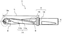
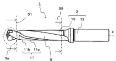
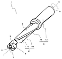
- the drill 1 of the first embodiment includes a drill body 3, a pair of main cutting edges 5, a sub cutting edge 7, a pair of chip discharge grooves 9 (hereinafter also simply referred to as discharge grooves 9), and a pair of lands. And a fluted land 11.
- the drill body 3 has a rotation axis X and has a rod-like configuration extending along the rotation axis X.
- the drill body 3 of the present embodiment includes a gripping portion 13 called a shank that is gripped by a rotating spindle or the like of a machine tool, and a cutting called a body that is located on the tip side of the gripping portion 13.
- Part 15 The grip 13 is a part designed according to the shape of the rotation axis X of the machine tool.
- the cutting part 15 is a part which contacts a work material, and is a part having a main role in the cutting work of the work material.
- An arrow Y1 in FIG. 1 indicates the rotation direction of the drill body 3.
- the pair of main cutting edges 5 are formed at the tip 3 a of the drill body 3, that is, at the tip of the cutting part 15. Further, a sub-cutting blade 7 is also formed at the tip 3 a of the drill body 3. The sub cutting edge 7 is located at the tip 3 a of the drill body 3 and connects the pair of main cutting edges 5. The workpiece is cut by the pair of main cutting edges 5 and sub cutting edges 7.
- the pair of main cutting edges 5 in the present embodiment are configured to have a concave curve shape when viewed from the tip. Thereby, the chips generated by the pair of main cutting edges 5 can be easily curled, so that the chips can be easily discharged by the pair of discharge grooves 9.
- the rotational trajectories of the pair of main cutting edges 5 are inclined with respect to the rotational axis X when the rotational trajectories of the pair of main cutting edges 5 are viewed in a cross section including the rotational axis X. It is provided as follows.
- the pair of main cutting edges 5 are located apart via the auxiliary cutting edge 7.
- the pair of main cutting edges 5 have a rotational symmetry of 180 ° with respect to the central axis of the drill body 3 in the front end view. Since the pair of main cutting edges 5 are rotationally symmetric as described above, it is possible to suppress the vibration generated between the pair of main cutting edges 5 when the pair of main cutting edges 5 bite against the work material. Therefore, stable deep hole machining can be performed.
- the front end view means that the drill 1 is viewed from the front end 3 a side of the drill body 3.
- a pair of discharge grooves 9 are provided on the outer periphery of the cutting portion 15 in the drill body 3.
- the pair of discharge grooves 9 has end portions on the front end side connected to the pair of main cutting edges 5, respectively, and spirals around the rotation axis X from the pair of main cutting edges 5 toward the rear end of the drill body 3. It extends in a shape. At this time, in order to stably hold the drill main body 3 with a machine tool, the pair of discharge grooves 9 are formed only in the cutting portion 15 and are not formed in the holding portion 13.
- the pair of discharge grooves 9 has a main purpose of discharging chips generated by the pair of main cutting edges 5 and sub cutting edges 7. At the time of cutting, chips formed by one of the pair of main cutting edges 5a pass through the discharge groove 9a of the pair of discharge grooves 9 connected to the main cutting edge 5a, and the rear end of the drill body 3 Discharged to the side. Further, the chips formed by the other 5 b of the pair of main cutting edges 5 pass through the discharge groove 9 b connected to the other main cutting edge 5 b of the pair of discharge grooves 9, and the rear of the drill body 3. It is discharged to the end side.
- the helix angle of the pair of discharge grooves 9 in this embodiment is designed so that the twist angle of one discharge groove 9a and the twist angle of the other discharge groove 9b are the same.
- the twist angle of the pair of discharge grooves 9 in the present embodiment is designed to be constant from the front end to the rear end, but is not particularly limited to such a configuration.
- the pair of discharge grooves 9 may have a plurality of twist angles.
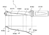
- the pair of discharge grooves 9 in the modification shown in FIGS. 13 to 15 includes a first region 9c, a second region 9d, and a third region 9e, respectively.
- the first region 9 c is located closest to the distal end side of the drill body 3 in the discharge groove 9 and is connected to the main cutting edge 5.
- the second region 9d is located closer to the rear end side of the drill body 3 than the first region 9c.
- the third region 9e is located closer to the rear end side of the drill body 3 than the second region 9d, and is located closest to the rear end side of the drill body 3 in the entire discharge groove 9.
- the ninth region 9c has a twist angle ⁇ 1, the second region 9d has a twist angle ⁇ 2, and the third region 9e has a twist angle ⁇ 3.
- the twist angle of the pair of discharge grooves 9 in this modification is not constant from the front end to the rear end. Specifically, as shown in FIG. 15, the twist angle ⁇ 2 in the second region 9d is smaller than the twist angle ⁇ 1 in the first region 9c. Further, the twist angle ⁇ 3 in the third region 9e is larger than the twist angle ⁇ 2 in the second region 9d.
- the first region 9c having a relatively large twist angle is positioned on the tip side of the cutting portion 15 so as to be connected to the main cutting edge 5. Therefore, the chips cut by the main cutting edge 5 are quickly sent out to the rear end side of the cutting portion 15 without stagnation near the main cutting edge 5.
- the discharge groove 9 in the present modification includes a second region 9d located on the rear end side of the cutting portion 15 with respect to the first region 9c. Therefore, it is possible to further send out the chips quickly sent out from the first region 9 c to the rear end side of the cutting portion 15. Further, since the second region 9d has a relatively small twist angle ⁇ 2, the rigidity of the drill body 3 can be increased as compared with the case where the twist angle ⁇ 2 has the same value as the twist angle ⁇ 1. .
- the chips sent out from the second area 9d have a longer distance from the first area 9c, and thus the flow of the chips tends to be delayed.
- the discharge groove 9 is located on the rear end side of the cutting portion 15 relative to the second region 9d, and includes a third region 9e having a relatively large twist angle. Therefore, the chips sent from the second region 9d to the third region 9e can be quickly discharged to the outside in the third region 9e having a relatively large twist angle.
- the twist angle ⁇ 1 can be set to about 15 to 45 °, for example.
- the twist angle ⁇ 2 can be set to about 3 to 20 °, for example.
- the twist angle ⁇ 3 can be set to about 15 to 30 °, for example.
- the twist angle ⁇ 1 of the first region 9c is set larger than the twist angle ⁇ 3 of the third region 9e.
- the first region 9 c in the discharge groove 9 is connected to the main cutting edge 5, and the chips are pushed out when the chips are generated at the main cutting edge 5 because the twist angle of the first region 9 c is the largest. Since the force is greatly applied, the chip discharge performance can be further improved.
- the pair of discharge grooves 9 in this modification further includes a first connection region 17 and a second connection region 19 in addition to the first region 9c, the second region 9d, and the third region 9e. .
- the first connection region 17 is located between the first region 9c and the second region 9d. That is, the second area 9 d is connected to the first area 9 c via the first connection area 17.
- the twist angle in the first connection region 17 smoothly changes from ⁇ 1 to ⁇ 2 from the front end side to the rear end side of the cutting portion 15. Therefore, the second region 9d is smoothly connected to the first region 9c via the first connection region 17.
- the second connection area 19 is located between the second area 9d and the third area 9e.
- the third region 9 e is connected to the second region 9 d through the second connection region 19.
- the twist angle in the second connection region 19 smoothly changes from ⁇ 2 to ⁇ 3 from the front end side to the rear end side of the cutting portion 15. Therefore, the third region 9e is smoothly connected to the second region 9d via the second connection region 19.
- the twist angle is different between the first region 9c and the second region 9d, the flow direction of chips changes between these regions. Therefore, between these areas, the flow of the chips is stagnant and the chips are easily clogged.
- the first connection region 17 that smoothly connects these regions is provided between the first region 9c and the second region 9d, the risk of clogging with chips can be reduced.
- the twist angle is different between the second region 9d and the third region 9e, the flow direction of chips changes between these regions.
- the possibility of clogging with chips can be reduced by providing the second connection region 19 that smoothly connects these regions between the second region 9d and the third region 9e.
- the length of the second region 9d in the direction parallel to the rotation axis X is longer than the length of the first region 9c and the third region 9e in the direction parallel to the rotation axis X. Too long.
- a load accompanying the cutting process is applied to the drill 1 and the cutting part 15 may bend.
- the central portion of the cutting portion 15 is easily bent more greatly than the front end portion and the rear end portion of the cutting portion 15.
- the length in the direction parallel to the rotation axis X of the second region 9d having a relatively small torsion angle and high rigidity is ensured to be relatively long compared to the first region 9c and the third region 9e. Therefore, durability against the bending of the cutting portion 15 can be improved.
- the length of the first region 9c in the direction parallel to the rotation axis X is 10 to 20% of the length of the entire discharge groove 9 in the direction parallel to the rotation axis X. Is set to about.
- the length of the second region 9d in the direction parallel to the rotation axis X is set to about 30 to 40% of the length of the entire discharge groove 9 in the direction parallel to the rotation axis X.
- the length of the third region 9e in the direction parallel to the rotation axis X is set to about 15 to 25% with respect to the length of the entire discharge groove 9 in the direction parallel to the rotation axis X.
- the discharge groove 9 in this modification has the 1st connection area
- the total length is not 100% with respect to the length in the direction parallel to the rotation axis X in the entire discharge groove 9.
- the length in the second region 9d having a relatively small twist angle is longer than the length in the first region 9c and the third region 9e having a relatively large twist angle,
- the overall length of the discharge groove 9 can be shortened without excessively inhibiting the flow of chips. Therefore, as a result, the chip dischargeability can be improved.
- the cutting part 15 in the present embodiment has a shape obtained by removing a portion corresponding to the pair of discharge grooves 9 from a column extending along the rotation axis X.
- a portion of the cutting portion 15 excluding the pair of discharge grooves 9, that is, a portion located between the pair of discharge grooves 9 is a land surface 11.
- the land surface 11 is adjacent to the discharge groove 9 at the rear in the rotation direction of the rotation axis X, and adjacent to the margin 11a at the rear of the rotation axis X in the rotation direction.
- a second surface 11b is adjacent to the discharge groove 9 at the rear in the rotation direction of the rotation axis X, and adjacent to the margin 11a at the rear of the rotation axis X in the rotation direction.
- the margin 11a has an arc shape located on the same circle.
- the diameter of this same circle corresponds to the outer diameter of the cutting part 15.
- the second surface 11b is a surface formed so as to avoid friction between the outer periphery of the drill body 3 and the work surface during cutting. Therefore, the distance from the rotation axis X is shorter than the margin 11a so that the gap between the second picking surface 11b and the work surface is provided.
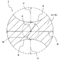
- the depth V of each of the pair of discharge grooves 9 can be set to about 10 to 40% with respect to the outer diameter of the cutting portion 15.
- the depth V of the discharge groove 9 is obtained by subtracting the distance between the bottom of the discharge groove 9 and the rotation axis X from the radius of the drill body 3 in a cross section orthogonal to the rotation axis X as shown in FIG. Means value. Therefore, the diameter W of the core thickness (web thickness) indicated by the diameter of the inscribed circle in the cross section orthogonal to the rotation axis X in the cutting portion 15 is about 30 to 80% with respect to the outer diameter of the cutting portion 15. Is set. Specifically, for example, when the outer diameter of the cutting portion 15 is 20 mm, the depth V of the discharge groove 9 can be set to about 2 to 8 mm.
- the torsion angle in the present embodiment is a virtual edge parallel to the rotation axis X passing through a leading edge (leading edge edge) that is an intersecting line formed by the discharge groove 9 and the margin 11a. It means the angle formed by a straight line.
- the outer diameter of the cutting portion 15 may be set to 6 mm to 42.5 mm.
- L 3D to 12D is set. That's fine.
- the drill body 3 is made of a cemented carbide containing WC (tungsten carbide) and Co (cobalt) as a binder, and TiC (titanium carbide) or TaC (tantalum carbide) is added to the cemented carbide.
- WC tungsten carbide
- Co cobalt
- TiC titanium carbide
- TaC tantalum carbide
- Examples include alloys containing materials, metals such as stainless steel and titanium.
- the cutting portion 15 in the present embodiment is such that a portion on the front end side including a pair of main cutting edges 5, a sub cutting edge 7, a part of the pair of discharge grooves 9 and a part of the pair of land surfaces 11 is a rear end part. It becomes the structure which can be attached or detached with respect to.
- the secondary cutting edge 7 in the present embodiment is located at the tip portion of the cutting portion 15 so as to connect the pair of main cutting edges 5.
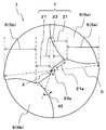
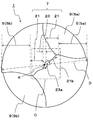
- the auxiliary cutting edge 7 has a pair of first chisel edge 21 and second chisel edge 23.
- the pair of first chisel edges 21 extend from the pair of main cutting edges 5 so as to approach the rotation axis X, respectively. Therefore, the pair of first chisel edges 21 extend from the pair of main cutting edges 5 toward the rotation axis X, respectively.
- the second chisel edge 23 connects the pair of first chisel edges 21. Of the entire chisel edge constituted by the pair of first chisel edges 21 and the second chisel edge 23, the pair of first chisel edges 21 functions as a thinning blade.
- the second chisel edge 23 is located at the center including the rotation axis X.
- a pair of first chisel edges 21 are positioned between both ends of the second chisel edge 23 and the pair of main cutting edges 5. Similar to the pair of main cutting edges 5, the second chisel edge 23 and the pair of first chisel edges 21 are 180 ° rotationally symmetric with respect to the rotation axis X of the drill body 3.
- the second chisel edge 23 and the pair of first chisel edges 21 have a role of cutting the work material together with the pair of main cutting edges 5.
- the cutting resistance applied to the sub cutting edge 7 is larger than that of the pair of main cutting edges 5. Therefore, for the purpose of ensuring the strength of the cutting edge, it is necessary to increase the inclination angle of the rotation locus of the secondary cutting edge 7 with respect to the rotation axis X when cutting along a virtual plane including the rotation axis X.
- the first chisel edge 21 is formed by, for example, removing a part of the chisel edge by thinning, the cross angle between the rake face and the flank face in the pair of first chisel edges 21 is the second chisel edge 23. This is smaller than the crossing angle between the rake face and the flank face. Therefore, when the second chisel edge 23 and the first chisel edge 21 are compared, the first chisel edge 21 tends to be less durable.
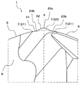
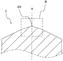
- the pair of first chisel edges 21 and the rotation trajectory X2 of the second chisel edge 23 are viewed in a cross section including the rotation axis X, the pair of first chisel edges Each of the rotation trajectories X1 has a linear shape. Thereby, since the intensity
- Each virtual straight line obtained by extending the rotation locus X1 of the pair of first chisel edges 21 toward the rotation axis X is located on the rear end side of the drill body 3 with respect to the rotation locus X2 of the second chisel edge 23. .
- the vibration which arises when a pair of main cutting edge 5 and the subcutting edge 7 bite against a work material can be suppressed, suppressing the fall of durability of the 1st chisel edge 21.
- FIG. As a result, it is possible to cut the work material satisfactorily while increasing the durability of the auxiliary cutting edge 7.
- the inclination angle ⁇ 2 of the locus with respect to the rotation axis X in the portion of the rotation locus X2 of the second chisel edge 23 near the rotation locus X1 is the rotation locus X1 of the pair of first chisel edges 21. It is smaller than the inclination angle ⁇ 1 with respect to the rotation axis X. Thereby, the biting to the work material in the 2nd chisel edge 23 can be made favorable.
- the pair of first chisel edges 21 in the present embodiment have not only a curved portion but also a straight portion 21a as shown in FIG.
- the straight portion 21a is smoothly connected to the adjacent second chisel edge 23 and the main cutting edge 5 via a curved portion.
- the drill having a thick core is intended to be a drill whose core thickness has a diameter of 0.3D to 0.5D with respect to the diameter D of the cutting portion 15, for example.
- the discharge groove 9 becomes shallow, so that the pair of main cutting edges 5 is shortened and the lengths of the pair of first chisel edge 21 and second chisel edge 23 are lengthened. Therefore, the force pulling the chips generated at the second chisel edge 23 and the pair of first chisel edges 21 by the chips generated by the pair of main cutting edges 5 is reduced. As a result, since the chips are difficult to be divided and extend long, there is a possibility that the chips are clogged in the chip discharge groove 9.
- each imaginary straight line obtained by extending the rotation locus X1 of the pair of first chisel edges 21 toward the rotation axis X is located on the rear end side of the drill body 3 with respect to the rotation locus X2 of the second chisel edge 23. Therefore, the second chisel edge 23 protrudes further away from the rear end than the extension line of the rotation locus X1 of the first chisel edge 21. In this way, the second chisel edge 23 and the first chisel edge 23 are projected by making the tip angle of the first chisel edge 21 and the second chisel edge 23 different from each other and projecting the second chisel edge 23 away from the rear end.
- the contact of the workpiece 21 with the workpiece 21 is not continuous but stepwise.
- the length of each of the pair of first chisel edges 21 can be shortened. Therefore, even when the discharge groove 9 is shallow, the pair of main cutting edges 5 are shortened, and the length of the pair of first chisel edges 21 is increased, the decrease in strength of the first chisel edges 21 is minimized. To the limit. As a result, even when the core thickness of the drill body 3 is increased, the work material can be cut more satisfactorily while increasing the durability of the auxiliary cutting edge 7.
- the second chisel edge 23 in the present embodiment has a straight portion 23a.
- the second chisel edge 23 is positioned so as to include the rotation axis X when the drill body 3 is viewed from the tip, and the second chisel edge 23 is closer to the rotation axis X than the pair of first chisel edges 21 and the pair of main cutting edges 5. It is formed at a close position. For this reason, the pair of first chisel edges 21 and the pair of main cutting edges 5 are cut so as to cut the workpiece, but the second chisel edge 23 has a relatively slow cutting speed. Cutting is easily performed by crushing the work material.
- the second chisel edge 23 has a straight portion 23a in the front end view. Since the second chisel edge 23 has such a straight portion 23a, the length of the second chisel edge 23 can be shortened, so that the durability of the auxiliary cutting edge 7 can be improved.
- the second chisel edge 23 and the first chisel edge 21 have straight portions 21a and 23a, respectively, and virtual straight lines along these portions intersect. Therefore, since distortion at the boundary between the chips generated at the second chisel edge 23 and the chips generated at the first chisel edge 21 increases, cracks are likely to occur in the chips generated at the second chisel edge 23. . As a result, even if the core thickness of the cutting part 15 is increased, the chips can be satisfactorily divided.
- the second chisel edge 23 is positioned on the rear end side of the drill body 3 with respect to the center portion 23c where both end portions 23b connected to the pair of first chisel edges 21 intersect the rotation axis X in a side view. Since the central portion 23c of the second chisel edge 23 protrudes away from the rear end, the portion of the second chisel edge 23 that intersects the rotation axis X protrudes away from the rear end. . Therefore, it is possible to suppress the shake that occurs when the pair of main cutting edges 5 and sub cutting edges 7 bite against the work material.
- the second chisel edge 23 in the present embodiment has a central portion in a side view from a direction orthogonal to the portion intersecting the rotation axis X in the second chisel edge 23.
- Reference numeral 23c denotes a convex curved surface shape.
- the central portion of the convex curved surface is the central portion 23c of the second chisel edge 23, and the central portion of the convex curved surface protrudes away from the rear end.
- the second chisel edge 23 has a sharp shape toward the side away from the rear end, it is possible to suppress the shake that occurs when the secondary cutting edge 7 bites against the work material. The durability of the second chisel edge 23 is lowered.
- the rake face and the flank face of the second chisel edge 23 intersect at an acute angle. Therefore, it is possible to suppress the shake that occurs when the auxiliary cutting edge 7 bites against the work material.
- the second chisel edge 23 is not an acute angle but a convex curved surface when viewed from the side perpendicular to the linear portion 23a of the second chisel edge 23 and the rotation axis X, the above-mentioned blur
- the durability of the second chisel edge 23 can be improved while suppressing the above.
- the pair of main cutting edges 5 in the present embodiment are configured to have a concave curve shape when viewed from the tip.
- the edge part by the side connected to the 1st chisel edge 21 in a concave curve-shaped part is a right angle or an acute angle.
- the tangent line of the concave curved portion of the pair of main cutting edges 5 and the end connected to the first chisel edge 21 and the virtual straight line along the straight portion 21a of the first chisel edge 21 are It is preferable that the imaginary straight line along the straight portion 21a of the first chisel edge 21 and the imaginary straight line along the straight portion 23a of the second chisel edge 23 intersect at an obtuse angle.
- the pair of first chisel edges 21, and the pair of main cutting edges 5 when adjacent cutting edge regions intersect at right angles or at an acute angle, distortion generated in the chips becomes excessively large, There is a possibility that the chips generated in the cutting edge region will be divided. In this case, cracks generated in the chips generated by the second chisel edge 23 are not transmitted to the chips generated by the pair of main cutting edges 5. Therefore, it becomes difficult to cut off the chips generated by the pair of main cutting edges 5 well.
- the second chisel edge 23 the pair of first chisel edges 21 and the pair of main cutting edges 5 are configured as described above, it is easy to generate cracks in the chips generated at the second chisel edge 23. At the same time, the cracks generated in the chips generated by the second chisel edge 23 can be well transmitted to the chips generated by the pair of main cutting edges 5.
- the inclination angle ⁇ 4 of the rake face 25a of the first chisel edge 21 with respect to a virtual straight line parallel to the rotation axis X is larger than the inclination angle ⁇ 5 of the rake face 25b of the second chisel edge 23, and
- the inclination angle ⁇ 6 of the rake face 25c of the pair of main cutting edges 5 with respect to the virtual straight line parallel to the rotation axis X is larger than the inclination angle ⁇ 4 of the rake face 25a of the first chisel edge 21.
- the rake angle of the second chisel edge 23, the first chisel edge 21, and the main cutting edge 5 in the cutting edge area located on the outer peripheral side of the drill main body 3 is larger, thereby further increasing the drill main body 3.
- the cutting speed can be increased in the cutting edge region located on the outer peripheral side of the.
- the chips generated at the second chisel edge 23 are easily pulled by the chips generated at the first chisel edge 21, and further, the chips generated at the first chisel edge 21 are generated at the main cutting edge 5. It becomes easy to be pulled by chips. As a result, cracks are more easily generated in the chips generated at the second chisel edge 23 and the first chisel edge 21, so that the chips can be divided more finely.
- a part of the rake face 25 b of the first chisel edge 21 is in the rotational direction Y ⁇ b> 1 rather than the first chisel edge 21. It is preferable that a part of the rake face 25c of the main cutting edge 5 is located behind the main cutting edge 5 in the rotational direction Y1.
- the pair of discharge grooves 9 in the drill 1 of the present embodiment has a groove width and a width at a major portion excluding a portion where the depth of the groove is sharply decreased, in other words, the groove is rounded up.
- the depth is substantially constant.
- an imaginary straight line X3 connecting the center portions of the pair of land surfaces 11 is formed with respect to the second chisel edge 23 as shown in FIG.
- the virtual straight line X3 that connects the center portions of the pair of land surfaces 11 located between the rear ends of the pair of discharge grooves 9 is the second chisel edge.
- 23 is preferably orthogonal to the straight portion 23a.
- FIG. 8 is a cross section including a rear end of a main portion that is orthogonal to the rotation axis X and has a substantially constant width or depth of the pair of discharge grooves 9. Moreover, what projected the main cutting blade 5 and the subcutting blade 7 in FIG. 8 is shown as the virtual line X4. Further, in the present specification, “perpendicular” does not mean that the angle is strictly 90 °, but also includes a deviation of about ⁇ 5 ° to 5 °.
- the rear ends of the pair of discharge grooves 9 in the present embodiment mean rear ends in main portions where the width or depth of the grooves is substantially constant. Therefore, it does not mean the rear end of the entire discharge groove 9, that is, the rear end of the portion where the depth of the groove is abruptly reduced.
- the rigidity of the drill 1 in the cross section in the direction orthogonal to the rotation axis X is the largest in the direction connecting the central portions of the pair of land surfaces 11. Therefore, a virtual straight line X3 that connects the central portions of the pair of land surfaces 11 at the rear ends of the pair of discharge grooves 9 that are greatly affected by the load is orthogonal to the second chisel edge 23. As a result, durability against the above-described load can be enhanced, and chatter vibration can be suppressed.
- the auxiliary cutting edge 7 is constituted by the second chisel edge 23 and the pair of first chisel edges 21, and the core of the cutting portion 15 at the rear end of the pair of discharge grooves 9.
- the diameter W of the thickness is larger than the chisel edge length of the second chisel edge 23.
- the core thickness of the cutting portion 15 is ensured sufficiently thick. Therefore, even when the feed amount of the drill 1 becomes large, it becomes possible to perform cutting stably.
- the drill 1 of the present embodiment is similar to the drill 1 of the first embodiment in that a drill body 3, a pair of main cutting edges 5, a sub cutting edge 7, and a pair of discharge grooves 9. And a pair of land surfaces 11.
- the sub cutting edge 7 in the drill 1 of this embodiment has a pair of 1st chisel edge 21 and 2nd chisel edge 23 similarly to the drill 1 of 1st Embodiment.
- the pair of first chisel edges 21 in the first embodiment have a straight portion 21a in the front end view.
- the pair of first chisel edges 21 in the present embodiment respectively have concave curved portions 21 b that are recessed toward the rear in the rotation direction of the rotation axis X in the front end view.
- the first chisel edge 21 is more than an imaginary straight line connecting the intersection of the first chisel edge 21 and the second chisel edge 23 and the intersection of the first chisel edge 21 and the main cutting edge 5. It has a concave curved portion 21b that is recessed rearward in the rotational direction of the rotation axis X in the front end view.
- the durability of the auxiliary cutting edge 7 can be improved even when the core thickness of the cutting portion 15 is increased.
- the chip discharging property. Can be increased.
- the chips cut by the first chisel edge 21 bend in accordance with the shape of the concave curved portion 21b. Therefore, the chips generated at the end of the first chisel edge 21 are pulled by the chips generated at the central portion of the first chisel edge 21. Therefore, the chips generated at the second chisel edge 23 adjacent to the first chisel edge 21 are pulled by the chips generated at the first chisel edge 21.
- the concave curve in the first chisel edge 21 in the front end view is smaller than the curvature of the concave-curved part in the pair of main cutting edges 5.
- the chips generated at the main chisel edge 21 are generated by the chips generated at the first chisel edge 21 more than the force pulling the chips generated at the main chisel edge 5. The pulling force tends to increase. Therefore, chips generated at the first chisel edge 21 can easily flow into the pair of discharge grooves 9 connected to the pair of main cutting edges 5.
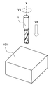
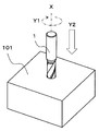
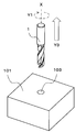
- the manufacturing method of the cut workpiece according to the present embodiment includes the following steps (1) to (4).
- This step can be performed, for example, by fixing the work material 101 on the table of the machine tool to which the drill 1 is attached and bringing the drill 1 close to the rotating state.
- the work material 101 and the drill 1 may be relatively close to each other.
- the work material 101 may be close to the drill 1.
- this step from the viewpoint of obtaining a good finished surface, it is preferable to set so that a partial region on the rear end side of the cutting portion of the drill 1 does not penetrate the work material 101. That is, by making this partial region function as a margin region for chip discharge, it is possible to achieve excellent chip discharge properties through the region.
- the work material 101 and the drill 1 may be relatively separated from each other.
- the work material 101 may be separated from the drill 1.
- the drill 1 is used. What is necessary is just to repeat the process which makes a pair of main cutting edge and subcutting edge of the drill 1 contact the different location of the workpiece 101, hold
- the shape of the cutting portion 15 is not limited to the configuration of the above-described embodiment, and other shapes that are usually used can be adopted.
- the cutting part 15 may be tapered so that the core thickness of the inscribed circle increases from the front end part toward the rear end part.
- the cutting part 15 may be inclined so that the drill diameter (outer diameter) increases or decreases as it goes from the front end portion toward the rear end portion.
- the cutting part 15 may be provided with a so-called undercut part or clearance part.
- the groove width of the pair of discharge grooves 9 is constant from the front end side to the rear end side. Instead, the groove width of the pair of discharge grooves 9 is rearward from the front end portion. You may make it become large or small as it goes to an edge part. Further, the groove widths of the pair of discharge grooves 9 may be different from each other. Further, the two grooves may be joined by changing the twist angle of either one or both of the pair of discharge grooves 9.
- part of a rear-end part side was replaced with this, the cutting part 15 replaced with this. It is good also as the drill 1 which consists of one member. Even in this case, the same effect as the drill 1 according to the above-described embodiment can be obtained.
Landscapes
- Engineering & Computer Science (AREA)
- Mechanical Engineering (AREA)
- Drilling Tools (AREA)
Abstract
Priority Applications (4)
| Application Number | Priority Date | Filing Date | Title |
|---|---|---|---|
| EP14787474.7A EP2990145B1 (fr) | 2013-04-26 | 2014-04-24 | Foret et procédé permettant de fabriquer un produit coupé à l'aide de ce dernier |
| US14/787,092 US9962773B2 (en) | 2013-04-26 | 2014-04-24 | Drill and method for manufacturing cut product using same |
| JP2015513836A JP6122487B2 (ja) | 2013-04-26 | 2014-04-24 | ドリルおよびそれを用いた切削加工物の製造方法 |
| US15/970,032 US10300535B2 (en) | 2013-04-26 | 2018-05-03 | Drill and method for manufacturing cut product using same |
Applications Claiming Priority (8)
| Application Number | Priority Date | Filing Date | Title |
|---|---|---|---|
| JP2013-093769 | 2013-04-26 | ||
| JP2013093769 | 2013-04-26 | ||
| JP2013177534 | 2013-08-29 | ||
| JP2013-177534 | 2013-08-29 | ||
| JP2013192860 | 2013-09-18 | ||
| JP2013-192860 | 2013-09-18 | ||
| JP2013-192861 | 2013-09-18 | ||
| JP2013192861 | 2013-09-18 |
Related Child Applications (2)
| Application Number | Title | Priority Date | Filing Date |
|---|---|---|---|
| US14/787,092 A-371-Of-International US9962773B2 (en) | 2013-04-26 | 2014-04-24 | Drill and method for manufacturing cut product using same |
| US15/970,032 Continuation US10300535B2 (en) | 2013-04-26 | 2018-05-03 | Drill and method for manufacturing cut product using same |
Publications (1)
| Publication Number | Publication Date |
|---|---|
| WO2014175396A1 true WO2014175396A1 (fr) | 2014-10-30 |
Family
ID=51791962
Family Applications (1)
| Application Number | Title | Priority Date | Filing Date |
|---|---|---|---|
| PCT/JP2014/061610 Ceased WO2014175396A1 (fr) | 2013-04-26 | 2014-04-24 | Foret et procédé permettant de fabriquer un produit coupé à l'aide de ce dernier |
Country Status (4)
| Country | Link |
|---|---|
| US (2) | US9962773B2 (fr) |
| EP (1) | EP2990145B1 (fr) |
| JP (1) | JP6122487B2 (fr) |
| WO (1) | WO2014175396A1 (fr) |
Cited By (5)
| Publication number | Priority date | Publication date | Assignee | Title |
|---|---|---|---|---|
| WO2020054702A1 (fr) * | 2018-09-12 | 2020-03-19 | 京セラ株式会社 | Insert de coupe, outil rotatif et procédé de production d'une pièce ouvrée coupée |
| CN112789132A (zh) * | 2018-10-04 | 2021-05-11 | 伊斯卡有限公司 | 顶端部分具有设有负前角和正前角的径向延伸的前切削刃的切削刀头以及旋转切削工具 |
| JP6985569B1 (ja) * | 2021-01-27 | 2021-12-22 | 住友電工ハードメタル株式会社 | ドリル |
| JP2022142055A (ja) * | 2021-03-16 | 2022-09-30 | ダイジ▲ェ▼ット工業株式会社 | ドリル |
| JP7380813B1 (ja) | 2022-11-29 | 2023-11-15 | 株式会社タンガロイ | 穴あけ工具 |
Families Citing this family (11)
| Publication number | Priority date | Publication date | Assignee | Title |
|---|---|---|---|---|
| KR101964754B1 (ko) * | 2017-08-09 | 2019-04-03 | 한국야금 주식회사 | 인덱서블 드릴 |
| USD882791S1 (en) * | 2018-01-31 | 2020-04-28 | Beijing Smtp Technology Co., Ltd. | Ultrasonic cutter head |
| USD882785S1 (en) * | 2018-01-31 | 2020-04-28 | Beijing Smtp Technology Co., Ltd. | Ultrasonic cutter head |
| USD892326S1 (en) * | 2018-01-31 | 2020-08-04 | Beijing Smtp Technology Co., Ltd. | Ultrasonic cutter head |
| USD882082S1 (en) * | 2018-01-31 | 2020-04-21 | Beijing Smtp Technology Co., Ltd. | Ultrasonic cutter head |
| USD882786S1 (en) * | 2018-01-31 | 2020-04-28 | Beijing Smtp Technology Co., Ltd. | Ultrasonic cutter head |
| USD882794S1 (en) * | 2018-01-31 | 2020-04-28 | Beijing Smtp Technology Co., Ltd. | Ultrasonic cutter head |
| GB2574652A (en) | 2018-06-14 | 2019-12-18 | Black & Decker Inc | Drilling tool |
| CN111347489A (zh) * | 2020-04-27 | 2020-06-30 | 华伟纳精密工具(昆山)有限公司 | Pcb短槽孔用钻针 |
| WO2023210572A1 (fr) * | 2022-04-29 | 2023-11-02 | 株式会社不二越 | Foret |
| CN117381028A (zh) * | 2022-07-05 | 2024-01-12 | 博世电动工具(中国)有限公司 | 钻头刀片及钻头 |
Citations (7)
| Publication number | Priority date | Publication date | Assignee | Title |
|---|---|---|---|---|
| JPH0396113U (fr) * | 1990-01-22 | 1991-10-01 | ||
| JP2002200510A (ja) * | 2000-12-27 | 2002-07-16 | Tsutomu Fuma | ドリル |
| JP2004034202A (ja) | 2002-07-02 | 2004-02-05 | Toshiba Tungaloy Co Ltd | 深穴加工用ドリル |
| JP2005125455A (ja) * | 2003-10-24 | 2005-05-19 | Hakuseisha:Kk | ドリル及びガイド孔用カッター及び円孔穿設方法 |
| JP2006224213A (ja) * | 2005-02-16 | 2006-08-31 | Hitachi Tool Engineering Ltd | ツイストドリル |
| JP2006528078A (ja) * | 2003-07-23 | 2006-12-14 | ケンナメタル インコーポレイテッド | ドリル |
| JP2012519602A (ja) * | 2009-03-11 | 2012-08-30 | ケンナメタル インコーポレイテッド | ドリルチップおよびドリルチップを有する穴あけ工具 |
Family Cites Families (45)
| Publication number | Priority date | Publication date | Assignee | Title |
|---|---|---|---|---|
| EP0088037A1 (fr) * | 1982-02-24 | 1983-09-07 | Hughes Tool Company | Foret pour une seule opération |
| SU1502228A1 (ru) * | 1987-04-06 | 1989-08-23 | Предприятие П/Я Г-4585 | Спиральное двухперовое сверло |
| EP0320881B2 (fr) * | 1987-12-14 | 2003-10-22 | Mitsubishi Materials Corporation | Foret hélicoidal |
| US4898503A (en) * | 1988-07-05 | 1990-02-06 | Lockheed Corporation | Twist drill |
| US4878788A (en) * | 1988-08-04 | 1989-11-07 | Kabushiki Kaisha Kobe Seiko Sho | Drill for drilling a thin plate |
| GB2260283A (en) * | 1991-10-03 | 1993-04-14 | Paul Mark Souber | Drill bit |
| JP3461538B2 (ja) * | 1993-09-14 | 2003-10-27 | 三菱マテリアル神戸ツールズ株式会社 | 超硬質ドリル |
| JPH09277108A (ja) * | 1996-02-14 | 1997-10-28 | Sumitomo Electric Ind Ltd | ドリル |
| US5807039A (en) * | 1997-02-13 | 1998-09-15 | Credo Tool Company | Drill bit |
| US5846035A (en) * | 1997-07-11 | 1998-12-08 | General Electric Company | Damage resistant drill |
| IL123858A (en) * | 1998-03-27 | 2003-05-29 | Iscar Ltd | Drilling head |
| US20030185640A1 (en) * | 2002-03-27 | 2003-10-02 | Eiji Ito | Multiple rake drill bits |
| DE10337985B4 (de) * | 2003-08-14 | 2005-07-28 | Mk Werkzeug-Service Manfred Krystek E.K. | Schweißpunktbohrer |
| EP1512476B1 (fr) * | 2003-09-08 | 2013-10-09 | Black & Decker Inc. | Foret à auto-centrage avec pointe pilote |
| US7101125B2 (en) * | 2003-12-17 | 2006-09-05 | Kennametal Inc. | Twist drill |
| IL159639A (en) * | 2003-12-29 | 2009-09-22 | Hanita Metal Works Ltd | Ballnose end mill |
| US7520703B2 (en) * | 2004-09-07 | 2009-04-21 | Black & Decker Inc. | Twist drill with a pilot tip |
| DE102004055198A1 (de) * | 2004-11-16 | 2006-05-18 | Daimlerchrysler Ag | Spiralbohrer |
| US7575401B1 (en) * | 2004-11-18 | 2009-08-18 | Precorp, Inc. | PCD drill for composite materials |
| JP2006281407A (ja) * | 2005-04-04 | 2006-10-19 | Osg Corp | 非鉄金属加工用ドリル |
| JP2007050477A (ja) * | 2005-08-18 | 2007-03-01 | Mitsubishi Materials Kobe Tools Corp | 超高圧焼結体チップ付きドリル |
| CN2820394Y (zh) * | 2005-09-14 | 2006-09-27 | 江苏天工工具股份有限公司 | 一种分屑强力钻 |
| US20080019787A1 (en) * | 2006-07-24 | 2008-01-24 | Karthikeyan Sampath | Drill for machining fiber reinforced composite material |
| JP2008093805A (ja) * | 2006-10-13 | 2008-04-24 | Osg Corp | ドリル |
| CN101879622B (zh) * | 2007-07-12 | 2012-08-22 | 本田技研工业株式会社 | 钻头 |
| DE102007050471A1 (de) * | 2007-10-23 | 2009-04-30 | MAPAL Fabrik für Präzisionswerkzeuge Dr. Kress KG | Werkzeug zur spanenden Bearbeitung von Werkstücken |
| DE102008004564B4 (de) * | 2008-01-15 | 2013-04-11 | EMUGE-Werk Richard Glimpel GmbH & Co. KG Fabrik für Präzisionswerkzeuge | Bohrwerkzeug mit Ausspitzung |
| US8061938B2 (en) * | 2008-03-10 | 2011-11-22 | Kennametal Inc. | Cutting tool with chisel edge |
| SE532432C2 (sv) * | 2008-05-09 | 2010-01-19 | Sandvik Intellectual Property | Borrkropp med primära och sekundära släppningsytor |
| DE102008029404A1 (de) * | 2008-06-23 | 2009-12-24 | Keil Werkzeugfabrik, Karl Eischeid Gmbh | Einsatzelement, Bohrwerkzeug mit Einsatzelement und Verfahren |
| CA2731128C (fr) * | 2008-06-28 | 2016-11-08 | Guhring Ohg | Outil de percage a aretes coupantes multiples |
| US8740515B2 (en) * | 2008-09-03 | 2014-06-03 | Black & Decker Inc. | Metal cutting drill bit |
| DE102008049509A1 (de) * | 2008-09-19 | 2010-03-25 | Mk-Tools-Service Gmbh | Bohrer |
| US7861807B2 (en) * | 2008-12-03 | 2011-01-04 | Black & Decker Inc. | Drill bit including one piece cutting head |
| US8408850B2 (en) * | 2009-06-16 | 2013-04-02 | Kennametal Inc. | Twist drill with negative axial rake transition between the lip and the secondary cutting edge |
| DE202010001892U1 (de) * | 2010-02-04 | 2010-05-06 | Adolf Würth GmbH & Co. KG | Spanwerkzeug mit einem Berührabschnitt zum Aufnehmen von Querkräften |
| GB201007032D0 (en) * | 2010-04-27 | 2010-06-09 | Dormer Tools Ltd | Twist drill for advanced materials |
| US9539652B2 (en) * | 2010-04-30 | 2017-01-10 | Kennametal Inc. | Rotary cutting tool having PCD cutting tip |
| DE102010026271B4 (de) * | 2010-07-06 | 2019-02-14 | Kennametal Inc. | Bohrwerkzeug |
| ITTO20100839A1 (it) * | 2010-10-15 | 2012-04-16 | Utensileria Navone S N C Di Navone Giovanni & C | Punta per utensile di foratura. |
| US8979445B2 (en) * | 2010-10-15 | 2015-03-17 | Hanita Metal Factory Ltd | Cutting tip and rotary cutting tool employing same |
| SE536296C2 (sv) * | 2011-02-08 | 2013-08-06 | Sandvik Intellectual Property | Borr med spånkanaler utformade för förbättrad spånevakuering |
| JP5051801B2 (ja) * | 2011-03-03 | 2012-10-17 | 株式会社ビック・ツール | ドリル |
| CN202180241U (zh) * | 2011-07-11 | 2012-04-04 | 宁波华刃工具有限公司 | 通用型多刃尖钻 |
| US9333564B2 (en) * | 2013-03-15 | 2016-05-10 | Black & Decker Inc. | Drill bit |
-
2014
- 2014-04-24 EP EP14787474.7A patent/EP2990145B1/fr active Active
- 2014-04-24 WO PCT/JP2014/061610 patent/WO2014175396A1/fr not_active Ceased
- 2014-04-24 JP JP2015513836A patent/JP6122487B2/ja active Active
- 2014-04-24 US US14/787,092 patent/US9962773B2/en active Active
-
2018
- 2018-05-03 US US15/970,032 patent/US10300535B2/en active Active
Patent Citations (7)
| Publication number | Priority date | Publication date | Assignee | Title |
|---|---|---|---|---|
| JPH0396113U (fr) * | 1990-01-22 | 1991-10-01 | ||
| JP2002200510A (ja) * | 2000-12-27 | 2002-07-16 | Tsutomu Fuma | ドリル |
| JP2004034202A (ja) | 2002-07-02 | 2004-02-05 | Toshiba Tungaloy Co Ltd | 深穴加工用ドリル |
| JP2006528078A (ja) * | 2003-07-23 | 2006-12-14 | ケンナメタル インコーポレイテッド | ドリル |
| JP2005125455A (ja) * | 2003-10-24 | 2005-05-19 | Hakuseisha:Kk | ドリル及びガイド孔用カッター及び円孔穿設方法 |
| JP2006224213A (ja) * | 2005-02-16 | 2006-08-31 | Hitachi Tool Engineering Ltd | ツイストドリル |
| JP2012519602A (ja) * | 2009-03-11 | 2012-08-30 | ケンナメタル インコーポレイテッド | ドリルチップおよびドリルチップを有する穴あけ工具 |
Non-Patent Citations (1)
| Title |
|---|
| See also references of EP2990145A4 * |
Cited By (13)
| Publication number | Priority date | Publication date | Assignee | Title |
|---|---|---|---|---|
| CN112672840A (zh) * | 2018-09-12 | 2021-04-16 | 京瓷株式会社 | 切削刀片、旋转工具及切削加工物的制造方法 |
| JPWO2020054702A1 (ja) * | 2018-09-12 | 2021-08-30 | 京セラ株式会社 | 切削インサート、回転工具及び切削加工物の製造方法 |
| WO2020054702A1 (fr) * | 2018-09-12 | 2020-03-19 | 京セラ株式会社 | Insert de coupe, outil rotatif et procédé de production d'une pièce ouvrée coupée |
| JP7168673B2 (ja) | 2018-09-12 | 2022-11-09 | 京セラ株式会社 | 切削インサート、回転工具及び切削加工物の製造方法 |
| CN112672840B (zh) * | 2018-09-12 | 2023-10-13 | 京瓷株式会社 | 切削刀片、旋转工具及切削加工物的制造方法 |
| CN112789132B (zh) * | 2018-10-04 | 2024-01-23 | 伊斯卡有限公司 | 顶端部分具有设有负前角和正前角的径向延伸的前切削刃的切削刀头以及旋转切削工具 |
| CN112789132A (zh) * | 2018-10-04 | 2021-05-11 | 伊斯卡有限公司 | 顶端部分具有设有负前角和正前角的径向延伸的前切削刃的切削刀头以及旋转切削工具 |
| JP6985569B1 (ja) * | 2021-01-27 | 2021-12-22 | 住友電工ハードメタル株式会社 | ドリル |
| WO2022162774A1 (fr) * | 2021-01-27 | 2022-08-04 | 住友電工ハードメタル株式会社 | Mèche |
| US12251765B2 (en) | 2021-01-27 | 2025-03-18 | Sumitomo Electric Hardmetal Corp. | Drill |
| JP2022142055A (ja) * | 2021-03-16 | 2022-09-30 | ダイジ▲ェ▼ット工業株式会社 | ドリル |
| JP2024078018A (ja) * | 2022-11-29 | 2024-06-10 | 株式会社タンガロイ | 穴あけ工具 |
| JP7380813B1 (ja) | 2022-11-29 | 2023-11-15 | 株式会社タンガロイ | 穴あけ工具 |
Also Published As
| Publication number | Publication date |
|---|---|
| EP2990145B1 (fr) | 2020-01-22 |
| US9962773B2 (en) | 2018-05-08 |
| US20160074944A1 (en) | 2016-03-17 |
| EP2990145A4 (fr) | 2016-12-07 |
| US10300535B2 (en) | 2019-05-28 |
| EP2990145A1 (fr) | 2016-03-02 |
| JPWO2014175396A1 (ja) | 2017-02-23 |
| JP6122487B2 (ja) | 2017-04-26 |
| US20180250756A1 (en) | 2018-09-06 |
Similar Documents
| Publication | Publication Date | Title |
|---|---|---|
| JP6122487B2 (ja) | ドリルおよびそれを用いた切削加工物の製造方法 | |
| JP7216698B2 (ja) | 切削工具及び切削加工物の製造方法 | |
| JP6470307B2 (ja) | ドリル及びそれを用いた切削加工物の製造方法 | |
| JP6473761B2 (ja) | エンドミルおよび切削加工物の製造方法 | |
| CN106536105B (zh) | 钻头及使用该钻头的切削加工物的制造方法 | |
| WO2018221737A1 (fr) | Outil rotatif | |
| JP2017124475A (ja) | ドリル | |
| JP6791985B2 (ja) | ドリル及びそれを用いた切削加工物の製造方法 | |
| JP6941047B2 (ja) | 回転工具及び切削加工物の製造方法 | |
| JP6725684B2 (ja) | 回転工具及びそれを用いた切削加工物の製造方法 | |
| JP6342662B2 (ja) | ドリルおよびそれを用いた切削加工物の製造方法 | |
| JP6110496B2 (ja) | ドリルおよびそれを用いた切削加工物の製造方法 | |
| JP6294095B2 (ja) | ドリルおよびそれを用いた切削加工物の製造方法 | |
| KR20150121645A (ko) | 비대칭 드릴 | |
| JP6462364B2 (ja) | スローアウェイ式ドリル及びそれを用いた切削加工物の製造方法 | |
| JP4449355B2 (ja) | ドリル | |
| JP2011125941A (ja) | ドリル |
Legal Events
| Date | Code | Title | Description |
|---|---|---|---|
| 121 | Ep: the epo has been informed by wipo that ep was designated in this application |
Ref document number: 14787474 Country of ref document: EP Kind code of ref document: A1 |
|
| ENP | Entry into the national phase |
Ref document number: 2015513836 Country of ref document: JP Kind code of ref document: A |
|
| NENP | Non-entry into the national phase |
Ref country code: DE |
|
| WWE | Wipo information: entry into national phase |
Ref document number: 14787092 Country of ref document: US Ref document number: 2014787474 Country of ref document: EP |