WO2014175607A1 - Disjoncteur à gaz - Google Patents
Disjoncteur à gaz Download PDFInfo
- Publication number
- WO2014175607A1 WO2014175607A1 PCT/KR2014/003405 KR2014003405W WO2014175607A1 WO 2014175607 A1 WO2014175607 A1 WO 2014175607A1 KR 2014003405 W KR2014003405 W KR 2014003405W WO 2014175607 A1 WO2014175607 A1 WO 2014175607A1
- Authority
- WO
- WIPO (PCT)
- Prior art keywords
- contact
- arc
- inducing
- inducement
- gas
- Prior art date
- Legal status (The legal status is an assumption and is not a legal conclusion. Google has not performed a legal analysis and makes no representation as to the accuracy of the status listed.)
- Ceased
Links
Images



Classifications
-
- H—ELECTRICITY
- H01—ELECTRIC ELEMENTS
- H01H—ELECTRIC SWITCHES; RELAYS; SELECTORS; EMERGENCY PROTECTIVE DEVICES
- H01H33/00—High-tension or heavy-current switches with arc-extinguishing or arc-preventing means
- H01H33/70—Switches with separate means for directing, obtaining, or increasing flow of arc-extinguishing fluid
- H01H33/76—Switches with separate means for directing, obtaining, or increasing flow of arc-extinguishing fluid wherein arc-extinguishing gas is evolved from stationary parts; Selection of material therefor
-
- H—ELECTRICITY
- H01—ELECTRIC ELEMENTS
- H01H—ELECTRIC SWITCHES; RELAYS; SELECTORS; EMERGENCY PROTECTIVE DEVICES
- H01H33/00—High-tension or heavy-current switches with arc-extinguishing or arc-preventing means
- H01H33/70—Switches with separate means for directing, obtaining, or increasing flow of arc-extinguishing fluid
- H01H33/72—Switches with separate means for directing, obtaining, or increasing flow of arc-extinguishing fluid having stationary parts for directing the flow of arc-extinguishing fluid, e.g. arc-extinguishing chamber
- H01H33/74—Switches with separate means for directing, obtaining, or increasing flow of arc-extinguishing fluid having stationary parts for directing the flow of arc-extinguishing fluid, e.g. arc-extinguishing chamber wherein the break is in gas
-
- H—ELECTRICITY
- H01—ELECTRIC ELEMENTS
- H01H—ELECTRIC SWITCHES; RELAYS; SELECTORS; EMERGENCY PROTECTIVE DEVICES
- H01H33/00—High-tension or heavy-current switches with arc-extinguishing or arc-preventing means
- H01H33/02—Details
- H01H33/04—Means for extinguishing or preventing arc between current-carrying parts
- H01H33/08—Stationary parts for restricting or subdividing the arc, e.g. barrier plate
-
- H—ELECTRICITY
- H01—ELECTRIC ELEMENTS
- H01H—ELECTRIC SWITCHES; RELAYS; SELECTORS; EMERGENCY PROTECTIVE DEVICES
- H01H33/00—High-tension or heavy-current switches with arc-extinguishing or arc-preventing means
- H01H33/02—Details
- H01H33/04—Means for extinguishing or preventing arc between current-carrying parts
- H01H33/12—Auxiliary contacts on to which the arc is transferred from the main contacts
-
- H—ELECTRICITY
- H01—ELECTRIC ELEMENTS
- H01H—ELECTRIC SWITCHES; RELAYS; SELECTORS; EMERGENCY PROTECTIVE DEVICES
- H01H33/00—High-tension or heavy-current switches with arc-extinguishing or arc-preventing means
- H01H33/70—Switches with separate means for directing, obtaining, or increasing flow of arc-extinguishing fluid
- H01H33/7015—Switches with separate means for directing, obtaining, or increasing flow of arc-extinguishing fluid characterised by flow directing elements associated with contacts
- H01H33/7023—Switches with separate means for directing, obtaining, or increasing flow of arc-extinguishing fluid characterised by flow directing elements associated with contacts characterised by an insulating tubular gas flow enhancing nozzle
-
- H—ELECTRICITY
- H01—ELECTRIC ELEMENTS
- H01H—ELECTRIC SWITCHES; RELAYS; SELECTORS; EMERGENCY PROTECTIVE DEVICES
- H01H33/00—High-tension or heavy-current switches with arc-extinguishing or arc-preventing means
- H01H33/70—Switches with separate means for directing, obtaining, or increasing flow of arc-extinguishing fluid
- H01H33/7015—Switches with separate means for directing, obtaining, or increasing flow of arc-extinguishing fluid characterised by flow directing elements associated with contacts
- H01H33/7069—Switches with separate means for directing, obtaining, or increasing flow of arc-extinguishing fluid characterised by flow directing elements associated with contacts characterised by special dielectric or insulating properties or by special electric or magnetic field control properties
-
- H—ELECTRICITY
- H01—ELECTRIC ELEMENTS
- H01H—ELECTRIC SWITCHES; RELAYS; SELECTORS; EMERGENCY PROTECTIVE DEVICES
- H01H33/00—High-tension or heavy-current switches with arc-extinguishing or arc-preventing means
- H01H33/70—Switches with separate means for directing, obtaining, or increasing flow of arc-extinguishing fluid
- H01H33/7015—Switches with separate means for directing, obtaining, or increasing flow of arc-extinguishing fluid characterised by flow directing elements associated with contacts
- H01H33/7084—Switches with separate means for directing, obtaining, or increasing flow of arc-extinguishing fluid characterised by flow directing elements associated with contacts characterised by movable parts influencing the gas flow
Definitions
- the present invention relates to a gas circuit breaker for extinguishing arcs generated during shutoff operation using an arc extinguishing gas.
- Gas circuit breaker is a device that is installed on the electric line to protect the power system and power equipment by cutting off the current in case of an accident such as artificial line break or short circuit.
- a typical gas circuit breaker includes a fixed electrode and a movable electrode, and the fixed electrode and the movable electrode are separated from each other by a tripping operation of the movable electrode, and the SOHO gas compressed in the compression chamber (for example, sulfur hexafluoride (SF) 6 )) to extinguish the arc generated when the fixed electrode and the movable electrode are separated.
- the SOHO gas compressed in the compression chamber for example, sulfur hexafluoride (SF) 6
- an arc is formed between the end of the fixed electrode and the end of the movable electrode, which becomes longer with movement of the movable electrode until it is extinguished by the extinguishing gas.
- the problem to be solved by the present invention is to provide a gas circuit breaker capable of performing the arc extinguishing function with a smaller amount of arc extinguishing gas.
- the gas circuit breaker according to the embodiment of the present invention may be in a state of being in contact with the first arc inductive contact, the first contact portion having the first arc inductive contact, or the first arc inductive contact.
- an arc length limiting contact configured to be positioned at an end beyond the end of the first arc inducing contact when the second arc inducing
- the gas injection nozzle may be configured to move with the second arc inducing contact, and the arc length limiting contact may be secured to the gas injection nozzle.
- the first arc guide contact may be formed in a rod shape, and the arc length limiting contact may include an axial extension forming a through hole into which the first arc guide contact is inserted.
- the axial extension portion may be formed with a gas movement hole for the movement of the arc extinguishing gas.
- the axial extension may be disposed in the gas injection nozzle, and a gas circuit breaker according to an embodiment of the present invention may include a plurality of arc length limiting contacts extending radially from the axial extension and connected to the gas injection nozzle. It may further comprise a radial extension of the plurality of radial extensions may be spaced apart from each other through which the extinguishing gas can move.
- the arc length limiting contact may be formed at an end on the side of the second arc inducing contact and may have an arc tip having a relatively large arc resistance.
- the arc tip may be formed of an alloy containing copper and tungsten.
- the first contact portion may include an electrically conductive tubular member electrically connected to the first arc inductive contact.
- the arc length limiting contact may be electrically connected to the tubular member, wherein the arc length limiting contact is in contact with the first arc guided contact while the first arc guided contact is in contact with the second arc guided contact.
- the gas circuit breaker according to another embodiment of the present invention may further include an electric field relaxation shield electrically connected to the arc length limiting contact to perform an electric field relaxation action.
- the field relaxation shield may be disposed between the arc extinguishing gas injection nozzle and the tube member fixed to the outer circumferential surface of the extinguishing gas injection nozzle.
- the field relaxation shield may include an axial extension extending in the axial direction and a curved extension extending radially outward from an end of the axial extension.
- the gas circuit breaker according to another embodiment of the present invention may further include a contact member disposed between the field relaxation shield and the tube member and electrically connected to the field relaxation shield and the tube member, respectively.
- An arc length limiting contact may include a first arc inducing contact portion including a first arc inducing contact, and a state of contacting or being separated from the first arc inducing contact.
- a first arc inducing contact portion including a first arc inducing contact
- a state of contacting or being separated from the first arc inducing contact For limiting the arc length between second contact portions having a second arc guided contact that is formed to be movable relative to the first arc guided contact so as to be spaced apart from the second arc guided contact. And move together with the second arc inducing contact upon movement of the second arc inducing contact, the end of the side of the second arc inducing contact when the first arc inducing contact is farthest from the second arc inducing contact. And to be positioned at a point beyond an end of the first arc guide contact.
- An arc length limiting contact may include an axial extension forming a through hole into which the first arc inducing contact is inserted, and a radial extension extending radially from the axial extension. Can be.
- the radial extensions may be provided in plurality and may be spaced apart from each other.
- the axial extension may have an arc tip having a relatively large arc resistance.
- the arc tip may be formed of an alloy containing copper and tungsten.
- arc energy is limited to implement the arc extinguishing function with a smaller amount of arc extinguishing gas, thereby reducing the volume of the gas circuit breaker and reducing the driving force. Reduction can be achieved.
- FIG. 1 is a cross-sectional view of an energized state of a gas circuit breaker according to an embodiment of the present invention.
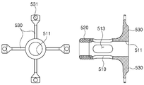
- FIG. 2 illustrates an arc length limiting contact of a gas circuit breaker according to an embodiment of the present invention.
- FIG 3 is a cross-sectional view of an electric field relaxation shield of the gas circuit breaker according to the embodiment of the present invention.
- FIG 4 is a view illustrating a state in which the first and second arc inducing contacts are moved relative to each other during the blocking operation in the gas circuit breaker according to the exemplary embodiment of the present invention.
- FIG. 5 is a view illustrating a state in which an arc is transferred to an arc length limiting contact during a blocking operation in a gas circuit breaker according to an exemplary embodiment of the present invention.
- the gas circuit breaker may include first and second housings 130 and 240 electrically connected to each other in a conventional energized state.
- the first housing 130 and the second housing 240 may be formed of a metal material having electrical conductivity, respectively, and spaced apart from each other along the axial direction (X-axis direction) as shown in FIG. 1. Can be arranged to face each other in a closed state.
- the gas circuit breaker includes a first contact portion 100 and the second contact portion 200 for performing the electrical connection and disconnection, and the arc induction function during the blocking operation.
- the operation of the first and second contact parts 100 and 200 enables electrical connection and disconnection of the first and second housings 130 and 240 and arc induction at the time of electrical disconnection.
- the first contact unit 100 may include a first main contact 144.
- the first main contact 144 may have a tubular shape and may be in contact with and electrically connected to the first housing 130.
- the first main contact 144 may be formed to contact the connection part 131 extending inward from the inner surface of the first housing 130.
- the second contact portion 200 is installed to be movable in the axial direction (the X-axis direction in FIG. 1).
- the second contact portion 200 may include a moving housing 220 and a second main contact 420 installed therein.
- the second main contact 420 is installed to move together with the moving housing 220, and is contacted or separated from the first main contact 144 according to the moving position.
- the second main contact 420 may be installed in contact with the flange portion 223 provided at the end of the mobile housing 220.
- the movable housing 220 is in contact with the second housing 240, and thus the second main contact 420 is electrically connected to the second housing 240 through the movable housing 220. Accordingly, the first and second housings 130 and 240 are electrically connected by the first main contact 144, the second main contact 420, and the movable housing 220.
- the first main contact 144, the second main contact 420, and the movable housing 220 may be formed of a material having electrical conductivity.
- the second main contact 420 when the second main contact 420 is in contact with the first main contact 114, the first and second housings 130 and 240 are electrically connected to each other to maintain an energized state. In operation, the second main contact 420 moves together with the movable housing 220 so that the second main contact 420 is separated from the first main contact 144.
- the first contact part 100 and the second contact part 200 may include a first arc induction contact 110 and a second arc induction contact 210 for inducing an arc at the time of electrical interruption, respectively.
- the first arc inductive contact 110 and the second arc inductive contact 210 may be formed of a material having electrical conductivity, respectively.
- the first arc induction contact 110 and the second arc induction contact 210 are electrically connected to each other by being in contact with each other when energized, and induced arcs while being separated from each other during an electrical shutdown operation. It performs the function.
- the second arc guide contact 210 is formed to be in contact with the first arc guide contact 110 (ie, energized state) or separated from the first arc guide contact 110.
- the second arc guide contact 210 may be formed to be relatively movable in the axial direction (X-axis direction in Figure 1) with respect to the first arc guide contact (110). That is, the second arc induction contact 210 is moved relative to the first arc induction contact 110 in the axial direction and is spaced apart from the first arc induction contact 110 as shown in FIGS. 4 and 5.
- the first arc induction contact 110 and the second arc induction contact 210 are spaced apart from each other to cut off the electrical connection and are separated from each other to induce the arc generated by the blocking operation.
- the first arc guide contact 110 may be configured to remain stationary in place, or in another example, may be configured to move slightly in a direction away from the second arc guide contact 210.
- the first arc inducing contact 110 is connected to the driving rod 113 and is formed to be movable within a predetermined range.
- the first arc guide contact 110 may have a rod shape as shown in FIG. 1, and a rear end of the first arc guide contact 110 may be connected to the connection member 120.
- the second arc inductive contact 210 may be fixed to the partition wall 221 provided in the mobile housing 220, and the partition wall 221 may be formed of a material having electrical conductivity similarly to the mobile housing 220. . Accordingly, the second arc inductive contact 210 may be electrically connected to the second moving housing 220 and the second housing 240.
- the second arc guide contact 210 may form a through hole 211 into which the tip portion of the first arc guide contact 110 is inserted. That is, as shown in FIG. 1, the first arc guide contact 110 is inserted into the through hole 211 of the second arc guide contact 210 in the normal energized state.
- a cover member 213 may be provided to surround the radially outer circumferential surface and the tip of the second arc guide contact 210.
- the cover member 213 may be formed of an electrically insulating material and may include a through hole 215 formed at a position corresponding to the through hole 211 of the second arc inductive contact 210.
- the cover member 213 may serve to protect the second arc guide contact 210 and to facilitate the compression and flow of the extinguishing gas.
- the front end portion of the first arc guide contact 110 is inserted through the through hole 215 of the cover member 213 and the through hole 211 of the second arc guide contact 210.
- the second arc inducing contact 210 may be installed to be connected to the driving rod 230 so as to be moved away from the first arc inducing contact 110 by the driving force of the driving rod 230.
- the driving rod 230 may be connected to the partition wall 221 of the mobile housing 220.
- an actuator may be provided to be connected to the driving rod 230 to drive the driving rod 230.
- the movable housing 220 may be moved in the axial direction (lateral direction in FIG. 1) by the driving force of the driving rod 230, and accordingly, the second main contact 420 installed in the movable housing 220. And the second arc guide contact 210 may be moved in the axial direction.
- the gas circuit breaker includes a gas chamber 300 for storing the arc extinguishing gas
- the arc extinguishing gas stored in the gas chamber 300 is the first arc induction contact 110 and the second arc induction contact.
- the 210 is separated, an arc is generated while the pressure is increased by an arc generated between the first arc guide contact 110 and the second arc guide contact 210. That is, in the case of an electrical short circuit or the like, when the electrical cutoff operation is performed for the electrical cutoff, the first main contact 144 and the second main contact 420 are separated by the movement of the movable housing 220, and further, the first cutoff is performed.
- the first arc induction contact 110 and the second arc induction contact 210 are separated by the movement of the two arc induction contact 210, where the first arc induction contact 110 and the second arc induction contact ( An electric arc is generated between 210 and the arc may be extinguished by an arc extinguishing gas whose pressure is increased by the arc.
- the extinguishing gas may be a gas having good extinguishing characteristics such as sulfur hexafluoride (SF 6 ).
- the gas injection nozzle 400 may be formed of an electrically insulating material and forms an injection passage of the extinguishing gas.
- the gas injection nozzle 400 may include a gas passage 410 extending in the axial direction.
- the gas passage 410 may include a portion 411 for receiving one side of the second arc guide contact 210, a portion 415 positioned on the opposite side thereof, and a neck portion 413 connecting both thereof.
- the neck portion 413 may be formed in a neck shape having a smaller diameter than the portions 411 and 415 positioned at both sides thereof.
- the neck portion 413 may have the same shape as the cross section of the rod-shaped first arc guide contact 110 and may have a slightly larger size.
- the gas injection nozzle 400 may be configured to move with the second arc guide contact 210.
- the gas injection nozzle 400 may be installed to move together with the second arc guide contact 210 by being fastened to the flange portion 223 of the moving housing 220.
- the gas circuit breaker according to the embodiment of the present invention has an arc length limiting contact 500.
- the arc length limiting contact 500 is arranged to be spaced apart from the second arc guide contact 210 and is configured to move together upon the movement of the second arc guide contact 210.
- the arc length limiting contact 500 may be coupled to the end of the gas injection nozzle 400 to move together with the second arc guide contact 210 when the moving housing 220 moves.
- the arc length limiting contact 500 may have the end 501 of the second arc induction contact 110 when the first arc induction contact 110 and the second arc induction contact 210 are as far apart as possible. It is configured to be positioned at a point beyond the end 111. Accordingly, as shown in FIG. 5, when the first arc induction contact 110 and the second arc induction contact 210 are separated by a certain degree or more, the end 501 of the arc length limiting contact 500 may be the first.
- the arc guide contact 110 is located closer to the second arc guide contact 210 than the end 111 of the arc guide contact 110. This structure allows the arc length limiting contact 500 to limit the arc length generated during the electrical interruption process. This will be described later.
- the guide tube 140 may be provided at one side of the first housing 130.
- the guide tube 140 may be connected to the first housing 130 by the connecting portion 131 as shown in FIG. 1.
- the arc length limiting contact 500 may be disposed to be positioned at the end of the guide tube 140 in the energized state as shown in FIG. 1, and the arc length limiting contact 500 will be described in more detail as follows.
- the arc length limiting contact 500 may be secured to the gas injection nozzle 400.
- it may be coupled to the tip of the gas injection nozzle 400.
- the arc length limiting contact 500 may include an axial extension 510 that forms a through hole 511 into which the first arc guide contact 110 is inserted.
- the axial extension part 510 is formed to extend in the moving direction of the second arc guide contact 210, that is, the axial direction (the X-axis direction in FIG. 1), and the through hole 511 is formed to extend in the axial direction. .
- the arc length limited contact 500 may include a plurality of radial extensions 530.
- the axial extension 510 of the arc length limiting contact 500 is disposed in the gas injection nozzle 400, and the radial extension 530 is the axial extension 530. At the end of the) may extend in the radial direction (Y-axis direction in FIG. 1) may be connected to the gas injection nozzle (400).
- the plurality of radial extensions 530 are formed to be spaced apart from each other so that the arc extinguishing gas can move therebetween. Accordingly, as shown in FIG. 5, the arc extinguishing gas may move through a space between the axial through hole 511 of the arc length limiting contact 500 and the plurality of radial extensions 530.
- a gas movement hole 513 may be formed in the axial extension 510 of the arc length limiting contact 500.
- the arc extinguishing gas can move to the inside and the outside of the axial extension 530 through the gas moving hole 513, so that the arc extinguishing gas can be more smoothly moved.
- the end of the axial extension 530 of the arc length limited contact 500 (ie, the end of the second arc guide contact 210 side) is formed of an arc tip 520 having a relatively large arc resistance Can be. Since an arc is formed at the end of the axial extension 530, this portion is formed into an arc tip 520 having a relatively high arc resistance, thereby damaging the end portion of the arc length limiting contact 500 by high arc energy. Can be minimized.
- arc tip 520 may be formed from an alloy containing copper and tungsten.
- the axial extension 530 except for the arc tip 520 may be formed of a copper material.
- the arc tip 520 is made of an arc resistant material that is relatively difficult to process and expensive to manufacture, thereby facilitating manufacture and manufacturing. The cost can be reduced.
- the arc length limiting contact 500 may be electrically connected to the guide tube 140 described above.
- the electric field relaxation shield 600 and the contact member 700 may be further provided, and the arc length limiting contact 500 may include the guide tube 140 through the electric field relaxation shield 600 and the contact member 700. Is electrically connected to the However, if the field relaxation shield 600 is omitted, the arc length limiting contact 500 may be electrically connected directly to the guide tube 140. By this structure, the arc length limiting contact 500 is electrically connected to the first housing 130.
- the field relaxation shield 600 is a member for relaxing an electric field in a blocking operation, and may be fastened to the radial extension 530 of the arc length limiting contact 500. Accordingly, the radial extension 530 of the arc length limiting contact 500 is in contact with and electrically connected to the field relaxation shield 600, and the field relaxation shield 600 is in contact with the guide tube 140 and electrically connected thereto. Can be connected.
- the electric field relaxation shield 600 may be formed in a tube shape capable of receiving one end of the gas injection nozzle 400, and may be formed of an electrically conductive material such as aluminum.
- the electric field relaxation shield 600 includes an axial extension part 610 extending in the axial direction, and the curved extension part 620 formed by rolling in a curved shape radially outward from the end of the axial extension part 610. It may include. By controlling the lengths and shapes of the axial extension 610 and the curved extension 620, an electric field relaxation effect can be obtained.
- the field relaxation shield 600 relaxes the electric field between the electrodes, thereby preventing breakdown.
- the electric field relaxation shield 600 may be provided with an accommodating groove 630 for accommodating the contact member 700, the contact member 700 is disposed in the accommodating groove 630 and the electric field relaxation shield 600 and By contacting each of the guide tubes 140, both can be electrically connected.
- the contact member 700 may be a ring spring formed of an electrically conductive material.
- the first housing 130, the mobile housing 220, and the first housing 130 are contacted by the contact of the first main contact 144 and the second main contact 420. 2 is maintained in the state in which the housing 240 is electrically connected.
- the first arc induction contact 110 and the second arc induction contact 210 are also electrically connected while maintaining contact with each other.
- the moving housing 220 is moved in the axial direction by the action of the driving rod 230, so that the second main contact 420 and the second arc induction contact 210 also Along with the movable housing 220 is moved away from the first housing 130 along the axial direction.
- the first arc induction contact 110 may also move slightly in a direction away from the second housing 240 by the driving rod 111. By this movement, the first main contact 144 and the second main contact 420 are separated from each other, and then the first arc guide contact 110 and the second arc guide contact 210 are also separated.
- FIG. 4 illustrates a first arc induction contact with the first main contact 144 and the second main contact 420 separated and the first arc induction contact 110 and the second arc induction contact 210 separated. An arc is formed between 110 and the second arc guide contact 210.
- the arc length limiting contact 500 is also moved by the same amount along with the movement of the second arc inducing contact 210.
- the end 501 of the arc length limiting contact 500 facing the induction contact 210 exceeds the end 111 of the first arc induction contact 110. That is, as shown in FIG. 5, the end 501 of the arc length limiting contact 500 is located closer to the second arc inducing contact 210 than the end 111 of the first arc inducing contact 110. do.
- While the tip 111 of the first arc guide contact 110 is located closer to the second arc guide contact 210 than the tip 501 of the arc length limited contact 500, as shown in FIG. An arc is formed between the end of the two arc inducing contact 210 and the end 111 of the first arc inducing contact 110, but the arcing time is increased so that the end of the arc length limiting contact 500 (501). The arc at the end 111 of the first arc guide contact 110 is transferred to the arc length limiting contact 500 at the moment the pass through the tip 111 of the first arc guide contact 110. Accordingly, as shown in FIG.
- the arc length limited contact 500 and the end length 501 of the arc length limited contact 500 pass through the end 111 of the first arc guided contact 110.
- the arc length is maintained no longer as the arc is maintained between the second arc inducing contacts 210. Accordingly, the maximum length of the arc is limited to the distance between the end of the second arc guide contact 210 and the end 501 of the arc length limiting contact 500.
- the arc length limiting contact according to the embodiment of the present invention has been described above, a separate description thereof will be omitted.
- the arc length limiting contact according to an embodiment of the present invention can be applied to various products that can be applied to the technical idea of limiting the arc length, such as switchgear as well as gas circuit breaker.
- the present invention relates to a gas circuit breaker and can be applied to an electric system, thereby having industrial applicability.
Landscapes
- Circuit Breakers (AREA)
- Arc-Extinguishing Devices That Are Switches (AREA)
Abstract
La présente invention concerne un disjoncteur à gaz comprenant : une première partie contact comportant un premier contact d'amorçage d'arc ; une seconde partie contact comportant un second contact d'amorçage d'arc formée de sorte à pouvoir se déplacer de manière relative par rapport au premier contact d'amorçage d'arc de façon à se trouver dans un état de contact avec le premier contact d'amorçage d'arc ou de séparation vis-à-vis du premier contact d'amorçage d'arc ; une chambre à gaz stockant un gaz d'extinction permettant l'extinction d'un arc généré entre le premier contact d'amorçage d'arc et le second contact d'amorçage d'arc lorsque le premier contact d'amorçage d'arc se trouve séparé du second contact d'amorçage d'arc ; une buse d'injection de gaz constituée d'un matériau électriquement isolant et qui forme un passage d'injection de gaz d'extinction ; et un contact de limitation de longueur d'arc agencé de sorte à être espacé du second contact d'amorçage d'arc et conçu pour se déplacer conjointement avec le second contact d'amorçage d'arc lorsque le second contact d'amorçage d'arc se déplace, une extrémité du second contact d'amorçage d'arc étant située au niveau d'un point qui se trouve au-delà d'une extrémité du premier contact d'amorçage d'arc lorsque le premier contact d'amorçage d'arc se trouve dans la position la plus éloignée vis-à-vis du second contact d'amorçage d'arc.
Priority Applications (2)
| Application Number | Priority Date | Filing Date | Title |
|---|---|---|---|
| EP14788665.9A EP2991092B1 (fr) | 2013-04-24 | 2014-04-18 | Disjoncteur à gaz |
| CN201480023393.6A CN105164780B (zh) | 2013-04-24 | 2014-04-18 | 气体断路器 |
Applications Claiming Priority (2)
| Application Number | Priority Date | Filing Date | Title |
|---|---|---|---|
| KR10-2013-0045668 | 2013-04-24 | ||
| KR1020130045668A KR101455324B1 (ko) | 2013-04-24 | 2013-04-24 | 가스 차단기 |
Publications (1)
| Publication Number | Publication Date |
|---|---|
| WO2014175607A1 true WO2014175607A1 (fr) | 2014-10-30 |
Family
ID=51792108
Family Applications (1)
| Application Number | Title | Priority Date | Filing Date |
|---|---|---|---|
| PCT/KR2014/003405 Ceased WO2014175607A1 (fr) | 2013-04-24 | 2014-04-18 | Disjoncteur à gaz |
Country Status (4)
| Country | Link |
|---|---|
| EP (1) | EP2991092B1 (fr) |
| KR (1) | KR101455324B1 (fr) |
| CN (1) | CN105164780B (fr) |
| WO (1) | WO2014175607A1 (fr) |
Families Citing this family (4)
| Publication number | Priority date | Publication date | Assignee | Title |
|---|---|---|---|---|
| KR102675868B1 (ko) * | 2017-01-09 | 2024-06-17 | 엘에스일렉트릭(주) | 가스절연 개폐장치의 가스 차단기 |
| US11217408B2 (en) * | 2017-11-10 | 2022-01-04 | Kabushiki Kaisha Toshiba | Gas circuit breaker |
| WO2019150550A1 (fr) | 2018-02-02 | 2019-08-08 | 株式会社東芝 | Disjoncteur à gaz |
| CN115410864B (zh) * | 2022-08-04 | 2024-11-15 | 广东电网有限责任公司 | 一种带气缸的快速接地开关及其使用方法 |
Citations (4)
| Publication number | Priority date | Publication date | Assignee | Title |
|---|---|---|---|---|
| US5850065A (en) * | 1996-02-22 | 1998-12-15 | Hitachi, Ltd. | Gas circuit breaker |
| KR20090072581A (ko) * | 2007-12-28 | 2009-07-02 | 현대중공업 주식회사 | 접촉튜브를 구비한 차단기 |
| KR20120088569A (ko) * | 2011-01-31 | 2012-08-08 | 토마스 앤드 베츠 인터내셔널, 인코포레이티드 | 고전압 스위치를 위한 플렉서블 밀봉 |
| KR20120097856A (ko) * | 2011-02-25 | 2012-09-05 | 엘에스산전 주식회사 | 가스 차단기의 소호부 |
Family Cites Families (4)
| Publication number | Priority date | Publication date | Assignee | Title |
|---|---|---|---|---|
| CH554597A (de) * | 1973-06-04 | 1974-09-30 | Sprecher & Schuh Ag | Druckgasschalter. |
| FR2692401B1 (fr) * | 1992-06-10 | 1994-08-19 | Gec Alsthom T & D Sa | Buse de disjoncteur à plusieurs divergents. |
| CN101120423B (zh) * | 2004-12-24 | 2010-06-23 | Abb技术有限公司 | 具有改进的断流容量的发电机开关 |
| US8063333B2 (en) * | 2008-02-05 | 2011-11-22 | Southern States, Inc. | Limited flash-over electric power switch |
-
2013
- 2013-04-24 KR KR1020130045668A patent/KR101455324B1/ko active Active
-
2014
- 2014-04-18 WO PCT/KR2014/003405 patent/WO2014175607A1/fr not_active Ceased
- 2014-04-18 CN CN201480023393.6A patent/CN105164780B/zh active Active
- 2014-04-18 EP EP14788665.9A patent/EP2991092B1/fr active Active
Patent Citations (4)
| Publication number | Priority date | Publication date | Assignee | Title |
|---|---|---|---|---|
| US5850065A (en) * | 1996-02-22 | 1998-12-15 | Hitachi, Ltd. | Gas circuit breaker |
| KR20090072581A (ko) * | 2007-12-28 | 2009-07-02 | 현대중공업 주식회사 | 접촉튜브를 구비한 차단기 |
| KR20120088569A (ko) * | 2011-01-31 | 2012-08-08 | 토마스 앤드 베츠 인터내셔널, 인코포레이티드 | 고전압 스위치를 위한 플렉서블 밀봉 |
| KR20120097856A (ko) * | 2011-02-25 | 2012-09-05 | 엘에스산전 주식회사 | 가스 차단기의 소호부 |
Also Published As
| Publication number | Publication date |
|---|---|
| EP2991092A1 (fr) | 2016-03-02 |
| KR101455324B1 (ko) | 2014-10-27 |
| CN105164780B (zh) | 2017-09-26 |
| CN105164780A (zh) | 2015-12-16 |
| EP2991092B1 (fr) | 2017-12-20 |
| EP2991092A4 (fr) | 2016-12-14 |
Similar Documents
| Publication | Publication Date | Title |
|---|---|---|
| TWI355121B (en) | Separable loadbreak connector and system with shoc | |
| US5981893A (en) | Electrical switching device | |
| KR101476580B1 (ko) | 과전압 차단기 | |
| WO2016108622A1 (fr) | Actionneur à répulsion électromagnétique pour disjoncteur | |
| JP5279910B2 (ja) | 低圧、中圧又は高圧のアセンブリ | |
| WO2014175607A1 (fr) | Disjoncteur à gaz | |
| KR101919125B1 (ko) | 고압 배전기의 가스절연 개폐장치 | |
| WO2016047891A1 (fr) | Disjoncteur isolé au gaz | |
| KR101520552B1 (ko) | 전기 절연기 | |
| US4525612A (en) | Gas insulated switch | |
| EP0088442A2 (fr) | Disjoncteur à autosoufflage | |
| ES2865422T3 (es) | Dispositivo de conmutación con doble carcasa conductora | |
| FI97753B (fi) | Kaasueristeinen kolminapainen korkeajännitekytkin | |
| CN206022215U (zh) | 真空气压式防电弧高压断路器 | |
| US4123636A (en) | Double-flow puffer-type single-pressure compressed-gas circuit-interrupter | |
| CN202260228U (zh) | 带有气体的绝缘的高压开关设备 | |
| EP2815414B1 (fr) | Disjoncteur à isolation gazeuse doté d'un agencement de blindage par contact nominal | |
| KR100606421B1 (ko) | 가스절연 차단기의 극간 전계완화장치 | |
| KR20150134206A (ko) | 가스절연 개폐장치의 가스차단기 | |
| WO2026049147A1 (fr) | Dispositif de buse de disjoncteur à isolation gazeuse | |
| RU180980U1 (ru) | Устройство блока высоковольтного предохранителя | |
| CN105552720B (zh) | 浪涌电压保护器 | |
| US10115546B2 (en) | Electrical tripout device integrating a circuit breaker and an isolator | |
| JPH0775131B2 (ja) | 高電圧用メタルクラツドしや断スイツチ | |
| RU181339U1 (ru) | Устройство дугогасительное высоковольтного выключателя |
Legal Events
| Date | Code | Title | Description |
|---|---|---|---|
| WWE | Wipo information: entry into national phase |
Ref document number: 201480023393.6 Country of ref document: CN |
|
| 121 | Ep: the epo has been informed by wipo that ep was designated in this application |
Ref document number: 14788665 Country of ref document: EP Kind code of ref document: A1 |
|
| WWE | Wipo information: entry into national phase |
Ref document number: 2014788665 Country of ref document: EP |
|
| NENP | Non-entry into the national phase |
Ref country code: DE |