WO2014178103A1 - Dispositif de lancement de jouet mobile et ensemble jouet mobile - Google Patents
Dispositif de lancement de jouet mobile et ensemble jouet mobile Download PDFInfo
- Publication number
- WO2014178103A1 WO2014178103A1 PCT/JP2013/062570 JP2013062570W WO2014178103A1 WO 2014178103 A1 WO2014178103 A1 WO 2014178103A1 JP 2013062570 W JP2013062570 W JP 2013062570W WO 2014178103 A1 WO2014178103 A1 WO 2014178103A1
- Authority
- WO
- WIPO (PCT)
- Prior art keywords
- traveling toy
- slide member
- belt body
- toy
- traveling
- Prior art date
- Legal status (The legal status is an assumption and is not a legal conclusion. Google has not performed a legal analysis and makes no representation as to the accuracy of the status listed.)
- Ceased
Links
Images

Classifications
-
- A—HUMAN NECESSITIES
- A63—SPORTS; GAMES; AMUSEMENTS
- A63H—TOYS, e.g. TOPS, DOLLS, HOOPS OR BUILDING BLOCKS
- A63H17/00—Toy vehicles, e.g. with self-drive; ; Cranes, winches or the like; Accessories therefor
- A63H17/008—Launching devices for motorless toy vehicles
Definitions
- the present invention relates to a traveling toy launching device and a traveling toy set for starting a traveling toy driven by rotation of a flywheel.
- Patent Document 1 includes a propulsion member that pushes the traveling toy from the rear, and the propulsion member stands by at the standby position against the biasing force of the spring.
- a traveling toy is set on the propulsion member, and a rotational force is applied to the flywheel by pulling out the belt body inserted into the traveling toy, and the pulled belt body acts on the propulsion member to release the standby of the propulsion member.
- a toy in which a propelling member pushes a traveling toy is disclosed.
- Patent Document 1 has a complicated structure, which increases the manufacturing cost. Further, the propulsion member must be moved to the standby position before departure, and the operation is complicated.
- the present invention provides a traveling toy launching device that can increase speed and traveling distance by giving sufficient acceleration at the time of departure, and that is simple in structure and can be accelerated only by pulling out the belt body. It is another object of the present invention to provide a traveling toy set.
- the present invention has been made to solve the above-described problems, and is characterized by the following.
- the traveling toy launching device is a traveling toy launching device that launches a traveling toy that is driven by rotation of a flywheel.
- the sliding member slides forward and the sliding toy slides forward by the urging force of the urging means when the belt body is completely pulled out. Characterized in that to the car.
- the invention described in claim 2 has the following features in addition to the features of the invention described in claim 1 described above. That is, a grip portion that can be gripped is provided on a side portion of the base body.
- a traveling toy set according to a third aspect includes the traveling toy launching device according to the first or second aspect, and a traveling toy that is driven by rotation of a flywheel.
- the present invention is as described above, and includes a base body, a slide member that is slidable on the base body, and an urging unit that urges the slide member forward.
- the sliding member slides backward due to the pulling resistance of the belt body, and when the belt body is completely pulled out, the sliding member moves the biasing means.
- the traveling toy is started by sliding forward by the urging force. For this reason, since sufficient acceleration can be given at the time of departure by the urging force of the urging means, the speed and travel distance can be increased.
- the basic configuration of the apparatus main body is only the base body, the slide member, and the urging means, the structure is simple and the manufacturing cost can be reduced. Further, since acceleration can be given only by pulling out the belt body, no special operation is required before and after departure, and operability is good.
- the grip body can be gripped and the apparatus main body can be fixed without providing a special installation place. it can.
- the traveling toy set according to the present embodiment includes a traveling toy 40 and a traveling toy launching device 10 that causes the traveling toy 40 to depart.
- the traveling toy 40 is driven by rotation of a flywheel 41 pivotally supported inside.
- the flywheel 41 is provided integrally with the wheel of the traveling toy 40, and the rotational force is maintained by the flywheel 41 rotating due to inertia, so that the traveling toy 40 travels by rotating the wheel. Is formed.
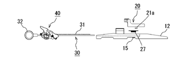
- the traveling toy launching device 10 includes an apparatus main body 11 on which the traveling toy 40 can be placed, and a belt body 30 that applies a rotational force to the flywheel 41 of the traveling toy 40.
- the belt body 30 includes a belt-shaped rack gear 31 inserted into the traveling toy 40 and a ring-shaped finger hook portion 32 formed at the rear end of the rack gear 31. It is.
- the belt body 30 is used by being inserted into the traveling toy 40. That is, the traveling toy 40 includes an insertion passage that penetrates forward and backward, and a pinion gear 42 is provided so as to face the insertion passage (see FIG. 4).
- the pinion gear 42 is integrally provided on the shaft of the flywheel 41.
- the flywheel 41 is formed so as to rotate integrally with the pinion gear 42 in the forward direction.
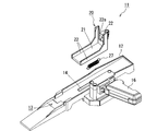
- the apparatus body 11 includes a base body 12, a slide member 20 that can slide on the base body 12, and a biasing means 27 that biases the slide member 20 forward. ing.
- the base body 12 is a member in which the traveling path 13 of the traveling toy 40 is formed on the upper surface, and a grip portion 16 is provided on the side so as to be substantially orthogonal to the traveling path 13.
- the traveling toy 40 can be started from the fixed apparatus main body 11.
- a guide groove 14 for guiding the sliding of the slide member 20 is formed on the upper surface of the traveling path 13 along the sliding direction of the slide member 20. Further, on the back surface of the travel path 13, a spring latching portion 15 for latching the biasing means 27 is formed to project.
- the slide member 20 is a substantially L-shaped member in a side view as shown in FIG. 2, and includes a bottom plate portion 21 that comes into contact with the upper surface of the traveling path 13, a back plate portion 22 that stands on the rear portion of the bottom plate portion 21, And side plate portions 23 erected on both side portions of the bottom plate portion 21.
- the bottom plate portion 21 is formed with a width and a depth that allow the traveling toy 40 to be accommodated, and the traveling toy 40 can be placed on the bottom plate portion 21 as shown in FIG.
- a protruding portion 21a is formed on the back surface of the bottom plate portion 21 so as to protrude downward.
- the protrusion 21 a is inserted into the guide groove 14 of the base body 12 described above, so that the slide member 20 can slide along the guide groove 14. Further, an urging means 27 is attached to the tip of the protruding portion 21a.
- the back plate portion 22 is a wall portion for supporting the back surface of the traveling toy 40. As will be described later, when the traveling toy 40 is pulled rearward by the belt body 30, the rear portion of the traveling toy 40 is supported by the back plate portion 22, so that the slide member 20 is integrated backward with the traveling toy 40. It has come to be pulled. Further, when the slide member 20 slides forward, the back plate portion 22 pushes out the back surface of the traveling toy 40 to start the traveling toy 40.
- the slit 22a is formed in the center. This slit 22a is formed for the purpose of avoiding the belt body 30 from interfering with the apparatus body 11 placed on the slide member 20 when the belt body 30 is inserted and removed.
- the side plate part 23 is a wall part for supporting the side part of the traveling toy 40.
- the side plate portion 23 is provided to prevent the traveling toy 40 from falling off the bottom plate portion 21 and to maintain the posture of the traveling toy 40 so as to face straight forward.
- the urging means 27 is a tension spring as shown in FIG. 2 and the like, and one end is attached to the spring hooking portion 15 of the base body 12 and the other end is attached to the protruding portion 21 a of the slide member 20.
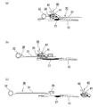
- the slide member 20 is urged forward by the urging means 27. Specifically, in the free state, as shown in FIGS. 1 and 4C, the slide member 20 is urged to the front end position of the guide groove 14, and is moved against the urging force of the urging means 27. If so, the slide member 20 is formed to be slidable along the guide groove 14 to the rear end position of the guide groove 14.
- the urging force of the urging means 27 is set so as to be weaker than the pull-out resistance of the belt body 30 when the flywheel 41 is started to rotate and to give the traveling toy 40 sufficient acceleration. .
- FIG. 4 is an explanatory diagram showing a state in which the traveling toy 40 is departed.
- the traveling toy 40 is set on the upper surface of the slide member 20 (on the bottom plate portion 21). Then, the rack gear 31 of the belt body 30 is inserted into the traveling toy 40.
- the rack gear 31 of the belt body 30 may be inserted into the traveling toy 40 in advance, and the traveling toy 40 with the belt body 30 inserted may be placed on the upper surface of the slide member 20.
- the slide member 20 is pulled backward by the pulling resistance of the belt body 30 and slides against the urging force of the urging means 27. That is, since a large torque is required at the start of rotation of the flywheel 41, the pull-out resistance of the belt body 30 is large. Since the biasing force of the biasing means 27 is weaker than the pulling resistance, the traveling toy 40 and the slide member 20 are pulled backward by the belt body 30 against the biasing force of the biasing means 27. Since the slide member 20 is guided to slide backward by the guide groove 14, it slides straight backward.
- the slide member 20 pushes out the traveling toy 40 to depart as shown in FIG. That is, since the belt body 30 is pulled out and the force for pulling the traveling toy 40 is lost, the slide member 20 slides forward by the biasing force of the biasing means 27.
- the back plate portion 22 pushes the traveling toy 40 forward, so that the traveling toy 40 is vigorously started by the momentum.
- the traveling toy 40 thus departed travels with a sufficient traveling distance and traveling speed by the pushed-out momentum and the rotation of the flywheel 41.
- the base body 12, the slide member 20 that can slide on the base body 12, and the biasing means 27 that biases the slide member 20 forward When the belt body 30 is pulled out with the traveling toy 40 set on the slide member 20, the slide member 20 slides backward due to the pulling resistance of the belt body 30, and the belt body 30
- the sliding member 20 is configured to slide forward by the urging force of the urging means 27 to start the traveling toy 40 when the pulling out of the toy 40 is completed. For this reason, since sufficient acceleration can be given at the time of departure by the urging force of the urging means 27, the speed and travel distance can be increased.
- the structure of the apparatus main body 11 is only the base body 12, the slide member 20, and the urging means 27, the structure is simple and the manufacturing cost can be reduced. Moreover, since acceleration can be given only by pulling out the belt body 30, no special operation is required before and after departure, and operability is good.
- the grip portion 16 that can be gripped is provided on the side portion of the base body 12, the grip body 16 can be gripped and the apparatus main body 11 can be fixed without providing a special installation place. 40 can be launched.
Landscapes
- Toys (AREA)
Abstract
La présente invention concerne un dispositif de lancement de jouet mobile et un ensemble jouet mobile tel que non seulement une accélération suffisante est apportée au lancement pour une plus grande vitesse et une distance de déplacement plus longue mais également ses structures sont simples et l'accélération peut être apportée rien qu'en tirant sur un corps de courroie. Le dispositif de lancement de jouet mobile possède un corps (12) de base, un élément coulissant (20) qui peut coulisser sur le corps (12) de base et un moyen de sollicitation (27) destiné à solliciter l'élément coulissant (20) vers l'avant. Lorsque le corps de courroie (30) est tiré alors qu'un jouet mobile (40) se trouve sur l'élément coulissant (20), l'élément coulissant (20) coulisse vers l'arrière en raison de la résistance à la traction du corps de courroie (30), et une fois que le corps de courroie (30) est complètement tiré, l'élément coulissant (20) coulisse vers l'avant en raison de la force de sollicitation du moyen de sollicitation (27) entraînant le lancement du jouet mobile (40).
Priority Applications (1)
| Application Number | Priority Date | Filing Date | Title |
|---|---|---|---|
| PCT/JP2013/062570 WO2014178103A1 (fr) | 2013-04-30 | 2013-04-30 | Dispositif de lancement de jouet mobile et ensemble jouet mobile |
Applications Claiming Priority (1)
| Application Number | Priority Date | Filing Date | Title |
|---|---|---|---|
| PCT/JP2013/062570 WO2014178103A1 (fr) | 2013-04-30 | 2013-04-30 | Dispositif de lancement de jouet mobile et ensemble jouet mobile |
Publications (1)
| Publication Number | Publication Date |
|---|---|
| WO2014178103A1 true WO2014178103A1 (fr) | 2014-11-06 |
Family
ID=51843256
Family Applications (1)
| Application Number | Title | Priority Date | Filing Date |
|---|---|---|---|
| PCT/JP2013/062570 Ceased WO2014178103A1 (fr) | 2013-04-30 | 2013-04-30 | Dispositif de lancement de jouet mobile et ensemble jouet mobile |
Country Status (1)
| Country | Link |
|---|---|
| WO (1) | WO2014178103A1 (fr) |
Citations (2)
| Publication number | Priority date | Publication date | Assignee | Title |
|---|---|---|---|---|
| JP3102994U (ja) * | 2004-01-26 | 2004-07-22 | 株式会社トミー | 二輪走行玩具 |
| US20110104981A1 (en) * | 2009-10-30 | 2011-05-05 | Nash Desent | Toy launcher and dual powered toy |
-
2013
- 2013-04-30 WO PCT/JP2013/062570 patent/WO2014178103A1/fr not_active Ceased
Patent Citations (2)
| Publication number | Priority date | Publication date | Assignee | Title |
|---|---|---|---|---|
| JP3102994U (ja) * | 2004-01-26 | 2004-07-22 | 株式会社トミー | 二輪走行玩具 |
| US20110104981A1 (en) * | 2009-10-30 | 2011-05-05 | Nash Desent | Toy launcher and dual powered toy |
Similar Documents
| Publication | Publication Date | Title |
|---|---|---|
| JP3164823U (ja) | コマ玩具発射装置 | |
| JP6255100B2 (ja) | コマ玩具 | |
| JP5801101B2 (ja) | バックスピントイ | |
| US7950976B2 (en) | Toy for rotating and launching an object | |
| AU2004322952A1 (en) | Wheel spinning launcher and wheel toy | |
| US8388405B2 (en) | Toy launcher and dual powered toy | |
| CN207371103U (zh) | 陀螺发射装置 | |
| WO2006110571A3 (fr) | Dispositif a lancette a activation par poussee | |
| US3877169A (en) | Vehicle-triggered toy vehicle accelerator | |
| CN201279388Y (zh) | 陀螺玩具发射装置 | |
| CN103313628B (zh) | 用于可移动家具部件的打开和闭合装置及弹出装置 | |
| JPS6148385B2 (fr) | ||
| JP2014076232A (ja) | バックスピントイ | |
| CN110711391A (zh) | 加速玩具系统 | |
| CN110721480B (zh) | 玩具车加速发射器 | |
| KR20150022267A (ko) | 팽이 발사 장치 | |
| JP6086376B2 (ja) | 可動役物ユニット | |
| JP2016098677A (ja) | リコイルスタータ | |
| JPWO2014199426A1 (ja) | 走行玩具及び走行玩具セット | |
| WO2014119220A1 (fr) | Jouet mobile | |
| JP2013223588A (ja) | 走行体玩具、及び走行玩具 | |
| JP2019088878A5 (fr) | ||
| CN212067729U (zh) | 一种陀螺发射车及陀螺 | |
| US4447898A (en) | Simplified sound reproducing device driven by a spring motor | |
| JP3071765U (ja) | コマの飛ばし装置 |
Legal Events
| Date | Code | Title | Description |
|---|---|---|---|
| 121 | Ep: the epo has been informed by wipo that ep was designated in this application |
Ref document number: 13883356 Country of ref document: EP Kind code of ref document: A1 |
|
| NENP | Non-entry into the national phase |
Ref country code: DE |
|
| 122 | Ep: pct application non-entry in european phase |
Ref document number: 13883356 Country of ref document: EP Kind code of ref document: A1 |
|
| NENP | Non-entry into the national phase |
Ref country code: JP |