WO2014178176A1 - Unité intérieure pour dispositifs de climatisation - Google Patents
Unité intérieure pour dispositifs de climatisation Download PDFInfo
- Publication number
- WO2014178176A1 WO2014178176A1 PCT/JP2014/002305 JP2014002305W WO2014178176A1 WO 2014178176 A1 WO2014178176 A1 WO 2014178176A1 JP 2014002305 W JP2014002305 W JP 2014002305W WO 2014178176 A1 WO2014178176 A1 WO 2014178176A1
- Authority
- WO
- WIPO (PCT)
- Prior art keywords
- pipe
- heat exchanger
- indoor
- indoor heat
- main body
- Prior art date
- Legal status (The legal status is an assumption and is not a legal conclusion. Google has not performed a legal analysis and makes no representation as to the accuracy of the status listed.)
- Ceased
Links
Images




Classifications
-
- F—MECHANICAL ENGINEERING; LIGHTING; HEATING; WEAPONS; BLASTING
- F24—HEATING; RANGES; VENTILATING
- F24F—AIR-CONDITIONING; AIR-HUMIDIFICATION; VENTILATION; USE OF AIR CURRENTS FOR SCREENING
- F24F1/00—Room units for air-conditioning, e.g. separate or self-contained units or units receiving primary air from a central station
- F24F1/06—Separate outdoor units, e.g. outdoor unit to be linked to a separate room comprising a compressor and a heat exchanger
- F24F1/26—Refrigerant piping
- F24F1/32—Refrigerant piping for connecting the separate outdoor units to indoor units
-
- F—MECHANICAL ENGINEERING; LIGHTING; HEATING; WEAPONS; BLASTING
- F24—HEATING; RANGES; VENTILATING
- F24F—AIR-CONDITIONING; AIR-HUMIDIFICATION; VENTILATION; USE OF AIR CURRENTS FOR SCREENING
- F24F1/00—Room units for air-conditioning, e.g. separate or self-contained units or units receiving primary air from a central station
- F24F1/0007—Indoor units, e.g. fan coil units
- F24F1/0043—Indoor units, e.g. fan coil units characterised by mounting arrangements
- F24F1/0047—Indoor units, e.g. fan coil units characterised by mounting arrangements mounted in the ceiling or at the ceiling
-
- F—MECHANICAL ENGINEERING; LIGHTING; HEATING; WEAPONS; BLASTING
- F24—HEATING; RANGES; VENTILATING
- F24F—AIR-CONDITIONING; AIR-HUMIDIFICATION; VENTILATION; USE OF AIR CURRENTS FOR SCREENING
- F24F1/00—Room units for air-conditioning, e.g. separate or self-contained units or units receiving primary air from a central station
- F24F1/0007—Indoor units, e.g. fan coil units
- F24F1/0043—Indoor units, e.g. fan coil units characterised by mounting arrangements
- F24F1/0057—Indoor units, e.g. fan coil units characterised by mounting arrangements mounted in or on a wall
-
- F—MECHANICAL ENGINEERING; LIGHTING; HEATING; WEAPONS; BLASTING
- F24—HEATING; RANGES; VENTILATING
- F24F—AIR-CONDITIONING; AIR-HUMIDIFICATION; VENTILATION; USE OF AIR CURRENTS FOR SCREENING
- F24F1/00—Room units for air-conditioning, e.g. separate or self-contained units or units receiving primary air from a central station
- F24F1/0007—Indoor units, e.g. fan coil units
- F24F1/0059—Indoor units, e.g. fan coil units characterised by heat exchangers
- F24F1/0063—Indoor units, e.g. fan coil units characterised by heat exchangers by the mounting or arrangement of the heat exchangers
-
- F—MECHANICAL ENGINEERING; LIGHTING; HEATING; WEAPONS; BLASTING
- F24—HEATING; RANGES; VENTILATING
- F24F—AIR-CONDITIONING; AIR-HUMIDIFICATION; VENTILATION; USE OF AIR CURRENTS FOR SCREENING
- F24F1/00—Room units for air-conditioning, e.g. separate or self-contained units or units receiving primary air from a central station
- F24F1/0007—Indoor units, e.g. fan coil units
- F24F1/0059—Indoor units, e.g. fan coil units characterised by heat exchangers
- F24F1/0067—Indoor units, e.g. fan coil units characterised by heat exchangers by the shape of the heat exchangers or of parts thereof, e.g. of their fins
-
- F—MECHANICAL ENGINEERING; LIGHTING; HEATING; WEAPONS; BLASTING
- F25—REFRIGERATION OR COOLING; COMBINED HEATING AND REFRIGERATION SYSTEMS; HEAT PUMP SYSTEMS; MANUFACTURE OR STORAGE OF ICE; LIQUEFACTION SOLIDIFICATION OF GASES
- F25B—REFRIGERATION MACHINES, PLANTS OR SYSTEMS; COMBINED HEATING AND REFRIGERATION SYSTEMS; HEAT PUMP SYSTEMS
- F25B39/00—Evaporators; Condensers
- F25B39/02—Evaporators
-
- F—MECHANICAL ENGINEERING; LIGHTING; HEATING; WEAPONS; BLASTING
- F25—REFRIGERATION OR COOLING; COMBINED HEATING AND REFRIGERATION SYSTEMS; HEAT PUMP SYSTEMS; MANUFACTURE OR STORAGE OF ICE; LIQUEFACTION SOLIDIFICATION OF GASES
- F25B—REFRIGERATION MACHINES, PLANTS OR SYSTEMS; COMBINED HEATING AND REFRIGERATION SYSTEMS; HEAT PUMP SYSTEMS
- F25B13/00—Compression machines, plants or systems, with reversible cycle
-
- F—MECHANICAL ENGINEERING; LIGHTING; HEATING; WEAPONS; BLASTING
- F25—REFRIGERATION OR COOLING; COMBINED HEATING AND REFRIGERATION SYSTEMS; HEAT PUMP SYSTEMS; MANUFACTURE OR STORAGE OF ICE; LIQUEFACTION SOLIDIFICATION OF GASES
- F25B—REFRIGERATION MACHINES, PLANTS OR SYSTEMS; COMBINED HEATING AND REFRIGERATION SYSTEMS; HEAT PUMP SYSTEMS
- F25B2500/00—Problems to be solved
- F25B2500/01—Geometry problems, e.g. for reducing size
-
- F—MECHANICAL ENGINEERING; LIGHTING; HEATING; WEAPONS; BLASTING
- F25—REFRIGERATION OR COOLING; COMBINED HEATING AND REFRIGERATION SYSTEMS; HEAT PUMP SYSTEMS; MANUFACTURE OR STORAGE OF ICE; LIQUEFACTION SOLIDIFICATION OF GASES
- F25B—REFRIGERATION MACHINES, PLANTS OR SYSTEMS; COMBINED HEATING AND REFRIGERATION SYSTEMS; HEAT PUMP SYSTEMS
- F25B2500/00—Problems to be solved
- F25B2500/18—Optimization, e.g. high integration of refrigeration components
Definitions
- the present invention relates to an indoor unit of an air conditioner, and particularly relates to space saving of piping around an indoor heat exchanger.
- an air conditioner disclosed in Patent Document 1 is connected to a casing, an indoor fan accommodated in the casing, an indoor heat exchanger arranged to surround the indoor fan, and a gas side communication pipe And a liquid side connection port connected to the liquid communication pipe. That is, the indoor unit is connected to the outdoor unit via the liquid communication pipe and the gas communication pipe.
- ⁇ A header is provided on the gas side piping, and a flow divider is provided on the liquid side piping.
- the header has a header body and a plurality of branch pipes branched from the header body and connected to the gas side end of the indoor heat exchanger.
- the shunt has a shunt main body and a plurality of shunt pipes (capillary tubes) branched from the shunt main body and connected to the liquid side end of the indoor heat exchanger.
- the refrigerant condensed in the outdoor heat exchanger flows into the liquid side pipe of the indoor unit via the liquid connection pipe.
- This refrigerant flows into the indoor heat exchanger from the flow divider and exchanges heat with the air conveyed by the indoor fan.
- the indoor heat exchanger absorbs heat from the indoor air and evaporates.
- the evaporated refrigerant flows into the gas side pipe from the header and flows out to the gas connection pipe.
- the refrigerant compressed by the compressor flows into the gas side pipe of the indoor unit via the gas connection pipe.
- This refrigerant flows into the indoor heat exchanger from the header and exchanges heat with the air conveyed by the indoor fan.
- the indoor heat exchanger the refrigerant dissipates heat to the indoor air and condenses.
- the condensed refrigerant flows into the liquid side pipe from the flow divider and flows out to the liquid connection pipe.
- the present invention has been made in view of such a point, and an object thereof is to provide an indoor unit of an air conditioner that can reduce the installation space of the liquid side piping and the gas side piping.
- the first invention includes an indoor fan (27), an indoor heat exchanger (32) arranged so as to surround the indoor fan (27), the indoor heat exchanger (32) and a gas communication pipe ( 3) a gas side pipe (70) that connects to the indoor heat exchanger (32) and a liquid side pipe (80) that connects the liquid communication pipe (2), and the room of the air conditioner installed on the ceiling Targeting the unit, the gas side pipe (70) is opposed to the header body (71a) and a header body (71a) extending vertically along the side end (32a) of the indoor heat exchanger (32).
- a curved pipe part (73) connecting the lower end part of the header body (71a) and the lower end part of the vertical pipe part (74), and the liquid side pipe (80 ) Is disposed in a space (S1) between the header body (71a), the vertical pipe part (74), and the curved pipe part (73).
- the lower end portion of the header main body (71a) and the lower end portion of the vertical pipe portion (74) facing the header main body (71a) are provided with a curved pipe portion (73 ).
- a space (S1) is formed between the header body (71a), the vertical pipe part (74), and the curved pipe part (73).
- a part of the liquid side pipe (80) is disposed in this space (S1). As a result, the space required for installing the liquid side pipe (80) is reduced.
- a second invention is characterized in that, in the first invention, an expansion valve (39) disposed inside the indoor heat exchanger (32) is connected to the liquid side pipe (80). To do.
- the expansion valve (39) is arranged inside the indoor heat exchanger (32). Therefore, the expansion valve (39) can be easily maintained from the indoor fan (27) side (for example, the suction port side).
- the liquid side pipe (80) includes a flow distributor body (81a) disposed outside the indoor heat exchanger (32), and the flow distributor body (81a). And a liquid relay pipe (82) connecting the expansion valve (39), and the liquid relay pipe (82) intersects with the curved pipe portion (73) of the gas side pipe (70). It is arranged above the curved pipe part (73).
- the expansion valve (39) is arranged inside the indoor heat exchanger (32), while the flow divider body (81a) is arranged outside the indoor heat exchanger (32). For this reason, the expansion valve (39) and the flow divider main body (81a) do not interfere with each other, and the space inside and outside the indoor heat exchanger (32) can be secured in a well-balanced manner.
- the flow divider body (81a) is arranged outside the indoor heat exchanger (32) and the expansion valve (39) is arranged inside the indoor heat exchanger (32)
- the liquid relay pipe connecting them (82) installation space is required.
- the liquid relay pipe (82) is disposed above the curved pipe portion (73) of the gas side pipe (70), the pipe space is prevented from becoming large in the horizontal direction. it can.
- a part of the liquid side pipe (80) is disposed in the space between the header body (71a), the vertical pipe part (74), and the curved pipe part (73) of the gas side pipe (70).
- the expansion valve (39) connected to the liquid side pipe (80) is arranged inside the indoor heat exchanger (32). For this reason, the expansion valve (39) can be easily maintained from the indoor fan (27) (suction grill) side.
- the expansion valve (39) is disposed inside the indoor heat exchanger (32), and the flow divider main body (81a) is disposed outside the indoor heat exchanger (32). . Therefore, according to the third invention, for example, the indoor heat exchanger (32) is compared with the case where the expansion valve (39) and the flow divider main body (81a) are arranged inside the indoor heat exchanger (32). The space inside is widened. Therefore, a sufficient installation space for the indoor fan (27) can be secured inside the indoor heat exchanger (32).
- the expansion valve (39) and the flow divider main body (81a) of the indoor heat exchanger (32) are compared with the case where the expansion valve (39) and the flow divider main body (81a) are arranged outside the indoor heat exchanger (32).
- the outside space becomes wider. Therefore, the casing that houses the indoor heat exchanger (32) can be reduced in the horizontal direction, and the indoor unit can be downsized.
- the liquid relay pipe (82) that connects the expansion valve (39) and the flow divider main body (81a) in the liquid side pipe (80) is disposed above the curved pipe section (73). ing. For this reason, the horizontal installation space of the liquid relay pipe (82) is reduced, and the indoor unit can be further miniaturized.
- FIG. 1 is a schematic piping system diagram showing a configuration of a refrigerant circuit of an air conditioner according to an embodiment.
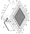
- FIG. 2 is a perspective view illustrating an appearance of the indoor unit according to the embodiment.
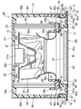
- FIG. 3 is a longitudinal sectional view showing the internal structure of the indoor unit according to the embodiment.
- FIG. 4 is a plan view of the interior of the indoor unit according to the embodiment as viewed from the top plate side.
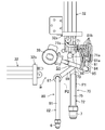
- FIG. 5 is a first perspective view illustrating a gas side pipe and a liquid side pipe according to the embodiment and peripheral structures thereof.
- FIG. 6 is a plan view showing a gas side pipe and a liquid side pipe according to the embodiment and peripheral structures thereof.
- FIG. 7 is a second perspective view showing a gas side pipe and a liquid side pipe and their peripheral structures according to the embodiment.
- the embodiment of the present invention is an air conditioner (10) that performs indoor cooling and heating.
- the air conditioner (10) includes an outdoor unit (11) installed outdoors and an indoor unit (20) installed indoors.
- the outdoor unit (11) and the indoor unit (20) are connected to each other by two connecting pipes (2, 3).
- a refrigerant circuit (C) is comprised in an air conditioner (10).
- a vapor compression refrigeration cycle is performed by circulating the filled refrigerant.
- the outdoor unit (11) is provided with a compressor (12), an outdoor heat exchanger (13), an outdoor expansion valve (14), and a four-way switching valve (15).
- the compressor (12) compresses the low-pressure refrigerant and discharges the compressed high-pressure refrigerant.
- a compression mechanism such as a scroll type or a rotary type is driven by the compressor motor (12a).
- the rotation speed (operation frequency) of the compressor motor (12a) is variable by an inverter device.
- the outdoor heat exchanger (13) is a fin-and-tube heat exchanger.
- An outdoor fan (16) is installed in the vicinity of the outdoor heat exchanger (13). In the outdoor heat exchanger (13), the air conveyed by the outdoor fan (16) and the refrigerant exchange heat.
- the outdoor fan (16) is constituted by a propeller fan driven by an outdoor fan motor (16a).
- the outdoor fan motor (16a) is configured such that its rotational speed is variable by an inverter device.
- the outdoor expansion valve (14) is an electronic expansion valve with a variable opening.
- the four-way switching valve (15) has first to fourth ports.
- the first port is connected to the discharge side of the compressor (12)
- the second port is connected to the suction side of the compressor (12)
- the third port is the outdoor heat exchanger (13 )
- the fourth port is connected to the gas-side stop valve (5).
- the four-way selector valve (15) switches between a first state (state indicated by a solid line in FIG. 1) and a second state (state indicated by a broken line in FIG. 1).
- the first port communicates with the third port
- the second port communicates with the fourth port.
- the four-way selector valve (15) in the second state the first port communicates with the fourth port and the second port communicates with the third port.
- the two communication pipes consist of a liquid communication pipe (2) and a gas communication pipe (3).
- One end of the liquid communication pipe (2) is connected to the liquid side closing valve (4), and the other end is connected to the liquid side end of the indoor heat exchanger (32).
- One end of the gas communication pipe (3) is connected to the gas side shut-off valve (5), and the other end is connected to the gas side end of the indoor heat exchanger (32).
- the indoor unit (20) is provided with an indoor heat exchanger (32) and an indoor expansion valve (39).
- the indoor heat exchanger (32) is a fin-and-tube heat exchanger.
- An indoor fan (27) is installed in the vicinity of the indoor heat exchanger (32).
- the indoor fan (27) is a centrifugal blower driven by an indoor fan motor (27a).
- the indoor fan motor (27a) is configured to have a variable rotational speed by an inverter device.
- the indoor expansion valve (39) is connected to the liquid end side of the indoor heat exchanger (32) in the refrigerant circuit (C).
- the indoor expansion valve (39) is an electronic expansion valve having a variable opening.
- the indoor unit (20) of the air conditioner (10) is configured to be embedded in the ceiling. That is, as shown in FIG. 3, the indoor unit (20) is fitted and attached to the opening (O) of the ceiling (U) facing the indoor space (R).
- the indoor unit (20) has an indoor unit main body (21) and a decorative panel (40) attached to the lower part of the indoor unit main body (21).
- the indoor unit body (21) has a box-shaped casing (22) having a substantially rectangular parallelepiped shape.
- the casing (22) has a substantially square top plate (23) in plan view and four substantially rectangular side plates (24) extending downward from the peripheral edge of the top plate (23), and the bottom surface An opening is formed in the.
- a vertically long box-shaped electrical component box (25) is attached to one side plate (24a) of the four side plates (24).
- a liquid side connection pipe (6) and a gas side connection pipe (7) connected to the indoor heat exchanger (32) pass through the side plate (24a).
- a liquid communication pipe (2) is connected to the liquid side connection pipe (6), and a gas communication pipe (3) is connected to the gas side connection pipe (7).
- an indoor fan (27), a bell mouth (31), an indoor heat exchanger (32), and a drain pan (36) are accommodated.
- the indoor fan (27) is disposed in the center of the casing (22).
- the indoor fan (27) includes an indoor fan motor (27a), a hub (28), a shroud (29), and an impeller (30).
- the indoor fan motor (27a) is supported by the top plate (23) of the casing (22).
- the hub (28) is fixed to the lower end of the drive shaft (27b) that is rotationally driven by the indoor fan motor (27a).
- the hub (28) includes an annular base (28a) formed radially outward of the indoor fan motor (27a), and a central bulge (28b) bulging downward from the inner peripheral edge of the base (28a). ).
- the shroud (29) is disposed below the base (28a) so as to face the base (28a) of the hub (28).
- a circular central suction port (29a) communicating with the inside of the bell mouth (31) is formed in the lower portion of the shroud (29).
- the impeller (30) is disposed in a blade accommodating space (29b) between the hub (28) and the shroud (29).
- the impeller (30) is composed of a plurality of turbo blades (30a) arranged so as to be along the rotation direction of the drive shaft (27b).
- the bell mouth (31) is located below the indoor fan (27).
- the bell mouth (31) has a circular opening at the upper end and the lower end, respectively, and is formed in a cylindrical shape whose opening area increases toward the decorative panel (40).
- the internal space (31a) of the bell mouth (31) communicates with the blade housing space (29b) of the indoor fan (27).
- the indoor heat exchanger (32) is provided with a refrigerant pipe (heat transfer tube) bent so as to surround the indoor fan (27).
- the indoor heat exchanger (32) is installed on the upper surface of the drain pan (36) so as to stand up.
- the air blown to the side from the indoor fan (27) passes through the indoor heat exchanger (32).
- the indoor heat exchanger (32) constitutes an evaporator that cools the air during the cooling operation, and constitutes a condenser (heat radiator) that heats the air during the heating operation.
- a drain pan (36) is disposed below the indoor heat exchanger (32).
- the drain pan (36) has an inner wall part (36a), an outer wall part (36b), and a water receiving part (36c).
- the inner wall portion (36a) is formed along the inner peripheral edge portion of the indoor heat exchanger (32), and is configured by an annular vertical wall standing upward.
- the outer wall portion (36b) is formed along the four side plates (24) of the casing (22), and is configured by an annular vertical wall that stands upward.
- the water receiving part (36c) is formed between the inner wall part (36a) and the outer wall part (36b), and is constituted by a groove for collecting condensed water generated in the indoor heat exchanger (32).
- each main body side blowing channel (37) each extending along the four side plates (24) are formed through the top and bottom of the outer wall (36b) of the drain pan (36).
- Each main body side blowing channel (37) communicates the space on the downstream side of the indoor heat exchanger (32) with the four panel side blowing channels (43) of the decorative panel (40).
- the indoor unit main body (21) is provided with a main body side heat insulating member (38).
- the main body side heat insulating member (38) is formed in a substantially box shape whose lower side is opened.
- the main body side heat insulating member (38) is formed along the top plate side heat insulating portion (38a) formed along the top plate (23) of the casing (22) and the side plate (24) of the casing (22).
- a circular through hole (38c) through which the upper end of the indoor fan motor (27a) passes is formed at the center of the top plate heat insulating part (38a).
- the side plate side heat insulating part (38b) is installed in the outer part of the main body side outlet channel (37) in the outer wall part (36b) of the drain pan (36).
- the decorative panel (40) is attached to the lower surface of the casing (22).
- the decorative panel (40) includes a panel body (41) and a suction grill (60).
- the panel body (41) is formed in a rectangular frame shape in plan view.
- the panel body (41) is formed with one panel side suction channel (42) and four panel side outlet channels (43).
- the panel-side suction channel (42) is formed at the center of the panel body (41).
- a suction port (42a) facing the indoor space (R) is formed at the lower end of the panel-side suction flow path (42).
- the panel-side suction channel (42) allows the suction port (42a) to communicate with the internal space (31a) of the bell mouth (31).
- a frame-like inner panel member (44) is fitted in the panel-side suction flow path (42).
- a dust collection filter (45) that captures dust in the air sucked from the suction port (42a) is provided inside the panel-side suction flow path (42).
- Each panel side outlet channel (43) is formed outside the panel side inlet channel (42) so as to surround the panel side inlet channel (42).
- Each panel side blowing channel (43) extends along four sides of each panel side suction channel (42). Air outlets (43a) facing the indoor space (R) are formed at the lower ends of the panel-side outlet channels (43), respectively.
- Each panel side blowing flow path (43) makes the corresponding blower outlet (43a) and the corresponding main body side blowing flow path (37) communicate.
- an inner heat insulating part (46) is provided inside the panel side blowing channel (43) (on the center part side of the panel body (41)).
- the outer side heat insulation part (47) is provided in the outer side (outer edge part side of a panel main body (41)) of the panel side blowing flow path (43).
- An inner seal member (48) interposed between the panel main body (41) and the drain pan (36) is provided on the upper surfaces of the inner heat insulating portion (46) and the outer heat insulating portion (47).
- the outer panel member (49) is fitted into the inner edge of the outer heat insulating portion (47).
- the outer panel member (49) has an inner wall portion (50) that constitutes an inner wall surface of the main body side outlet channel (37), and a lower end portion of the inner wall portion (50) toward an outer edge portion of the panel main body (41). And an extending portion (51) extending.
- the extension part (51) is formed in a rectangular frame shape along the lower surface of the ceiling (U).
- An outer seal member (52) interposed between the extension part (51) and the ceiling (U) is provided on the upper surface of the extension part (51).
- each body side blowing passage (37) is provided with a wind direction adjusting blade (53) for adjusting the wind direction of the air (blowing air) flowing through the body side blowing passage (37).
- the wind direction adjusting blade (53) is formed across both ends in the longitudinal direction of the main body outlet channel (37) along the side plate (24) of the casing (22).
- the wind direction adjusting blade (53) is configured to be rotatable about an axis of rotation (53a) extending in the longitudinal direction.
- the suction grill (60) is attached to the lower end (that is, the suction port (42a)) of the panel side suction flow path (42).
- the suction grill (60) includes a grill main body (61) facing the suction inlet (42a) and a rectangular extension (65 extending outward from the grill main body (61) toward each outlet (43a). ).
- the grill body (61) is formed in a substantially square shape in plan view.
- a large number of suction holes (63) are arranged in a lattice pattern at the center of the grill body (61). These suction holes (63) are constituted by through holes that penetrate the grill body (61) in the thickness direction (vertical direction).
- the suction hole (63) is formed in a square shape in the opening cross section.
- the extension portion (65) of the suction grill (60) is formed in a rectangular frame shape extending outward from the grill body (61) toward the outlet (43a).
- the extension part (65) overlaps with the panel body (41) in the vertical direction so as to overlap the lower surface of the inner heat insulating part (46).
- the side edge part of the extension part (65) has shifted to the suction inlet (42a) rather than the inner edge part of the blower outlet (43a).
- the four-way switching valve (15) shown in FIG. 1 is in a state indicated by a solid line, and the compressor (12), the indoor fan (27), and the outdoor fan (16) are in an operating state.
- the refrigerant circuit (C) a refrigeration cycle is performed in which the outdoor heat exchanger (13) serves as a condenser and the indoor heat exchanger (32) serves as an evaporator.
- the high-pressure refrigerant compressed by the compressor (12) flows through the outdoor heat exchanger (13) and exchanges heat with outdoor air.
- the outdoor heat exchanger (13) the high-pressure refrigerant dissipates heat to the outdoor air and condenses.
- the refrigerant condensed in the outdoor heat exchanger (13) is sent to the indoor unit (20).
- the refrigerant flows through the indoor heat exchanger (32) after being decompressed by the indoor expansion valve (39).
- room air flows upward in order through the suction port (42a), the panel-side suction flow path (42), and the internal space (31a) of the bell mouth (31), and accommodates the blades of the indoor fan (27). It is sucked into the space (29b).
- the air in the blade accommodating space (29b) is conveyed by the impeller (30) and blown out radially between the hub (28) and the shroud (29).
- This air passes through the indoor heat exchanger (32) and exchanges heat with the refrigerant.
- the refrigerant absorbs heat from the indoor air and evaporates, and the air is cooled by the refrigerant.
- the air cooled by the indoor heat exchanger (32) is diverted to each main body side outlet passage (37), then flows downward through the panel side outlet passage (43), and passes through the outlet (43a) to the indoor space ( To R).
- the refrigerant evaporated in the indoor heat exchanger (32) is sucked into the compressor (12) and compressed again. .
- the four-way switching valve (15) shown in FIG. 1 is in a state indicated by a broken line, and the compressor (12), the indoor fan (27), and the outdoor fan (16) are in an operating state.
- the refrigerant circuit (C) a refrigeration cycle is performed in which the indoor heat exchanger (32) serves as a condenser and the outdoor heat exchanger (13) serves as an evaporator.
- the high-pressure refrigerant compressed by the compressor (12) flows through the indoor heat exchanger (32) of the indoor unit (20).
- room air flows upward in order through the suction port (42a), the panel-side suction flow path (42), and the internal space (31a) of the bell mouth (31), and accommodates the blades of the indoor fan (27). It is sucked into the space (29b).
- the air in the blade accommodating space (29b) is conveyed by the impeller (30) and blown out radially between the hub (28) and the shroud (29). This air passes through the indoor heat exchanger (32) and exchanges heat with the refrigerant.
- the refrigerant dissipates heat to the indoor air and condenses, and the air is heated by the refrigerant.
- the air heated by the indoor heat exchanger (32) is diverted to each main body-side outlet passage (37), then flows downward through the panel-side outlet passage (43), and passes through the outlet (43a) to the indoor space ( To R).
- the refrigerant condensed in the indoor heat exchanger (32) is depressurized by the outdoor expansion valve (14) and then flows through the outdoor heat exchanger (13).
- the outdoor heat exchanger (13) the refrigerant absorbs heat from the outdoor air and evaporates.
- the refrigerant evaporated in the outdoor heat exchanger (13) is sucked into the compressor (12) and compressed again.
- the first end (32a) and the second end (32b) are formed in the indoor heat exchanger (32).
- the first side end (32a) is formed at one side end in the longitudinal direction of the heat transfer tube of the indoor heat exchanger (32), and the second side end (32b) is formed at the indoor heat exchanger (32). It is formed at the other side end in the longitudinal direction of the heat transfer tube.
- the gas side pipe (70) and the liquid side pipe (80) are connected to the pipe housing space (S) between the first side end (32a) and the second side end (32b) of the indoor heat exchanger (32). Installed.
- the gas side pipe (70) is formed between the gas side end of the indoor heat exchanger (32) and the gas side connection pipe (7) described above.
- the gas side pipe (70) includes a header (71) connected to the indoor heat exchanger (32), and a gas relay pipe (72) connected between the header (71) and the gas side connection pipe (7). And have.
- the header (71) is disposed in the vicinity of the first side end (32a) of the indoor heat exchanger (32).
- the header (71) includes a header body (71a) and a plurality of branch pipes (71b) branching from the header body (71a).
- the header body (71a) extends in the vertical direction along the first side end (32a) of the indoor heat exchanger (32). That is, the header main body (71a) is parallel to the first side end (32a) so as to be spaced from the first side end (32a) of the indoor heat exchanger (32).
- the header body (71a) joins the refrigerant that has flowed out of the branch pipes (71b) during cooling.
- the header body (71a) diverts the refrigerant that has flowed out of the gas relay pipe (72) to each branch pipe (71b) during heating.
- the plurality of branch pipes (71b) are disposed between the header body (71a) and the first side end (32a) of the indoor heat exchanger (32).
- Each branch pipe (71b) is arranged in a direction (vertical direction) along the side surface of the header body (71a) so as to be parallel to each other.
- One end of each branch pipe (71b) is connected to each heat transfer pipe of the first side end (32a) of the indoor heat exchanger (32). That is, the header (71) is connected to the heat transfer tube of the first side end (32a) among the side ends on both sides of the indoor heat exchanger (32).
- the other end of each branch pipe (71b) is connected to the header body (71a) and communicates with the inside of the header body (71a).
- the gas relay pipe (72) has a first curved pipe section (73) (curved pipe section) and a first vertical pipe section (74) (vertical) in order from the header body (71a) to the gas side connection pipe (7). Tube portion) and the first horizontal tube portion (75) are continuously formed.
- the first curved pipe portion (73) has a substantially U-shaped outer shape whose upper side is opened in a side view.
- the 1st curved pipe part (73) has connected the lower end part of the header main body (71a), and the lower end part of the 1st vertical pipe part (74).
- the first vertical pipe portion (74) extends in the vertical direction so as to face the lower side surface of the header body (71a).
- the 1st vertical pipe part (74) has connected the 1st curved pipe part (73) and the 1st horizontal pipe part (75).
- the 1st horizontal pipe part (75) is bent in the horizontal direction from the upper end part of the 1st vertical pipe part (74), and is connected with the gas side connection pipe (7).
- a vertically long space (S1) is formed between the header body (71a), the first curved pipe part (73), and the first vertical pipe part (74).
- the liquid side pipe (80) is formed between the liquid side end of the indoor heat exchanger (32) and the liquid side connecting pipe (6) described above.
- the liquid side pipe (80) includes a flow divider (81) and a liquid relay pipe (82) connected between the flow divider (81) and the liquid side connection pipe (6).
- the flow divider (81) is disposed in the vicinity of the first side end (32a) of the indoor heat exchanger (32).
- the shunt (81) has a shunt main body (81a) and a plurality of shunt pipes (81b) branched from the shunt main body (81a).
- the shunt main body (81a) is arranged outside the indoor heat exchanger (32). Specifically, when the virtual plane along the downstream surface near the first side end (32a) of the indoor heat exchanger (32) is P1 (see FIG. 6), the shunt main body (81a) It arrange
- the flow distributor main body (81a) is formed in a bottomed cylindrical shape whose axial center extends vertically, and a plurality of flow dividing tubes (81b) are connected to the upper end surface thereof.
- the flow divider main body (81a) diverts the refrigerant that has flowed out of the liquid relay pipe (82) to each of the diversion pipes (81b) during cooling.
- the flow divider main body (81a) joins the refrigerant that has flowed out of each flow dividing pipe (81b) during heating.
- the plurality of flow dividing tubes (81b) are disposed between the flow divider main body (81a) and the first side end (32a) of the indoor heat exchanger (32).
- Each branch pipe (81b) is constituted by a capillary tube having a smaller flow path diameter than the flow distributor body (81a).
- the liquid relay pipe (82) has a second vertical pipe section (83), a second curved pipe section (84), and a third vertical pipe section in order from the flow distributor main body (81a) toward the liquid side connection pipe (6). (85), second horizontal pipe part (86), third horizontal pipe part (87), fourth vertical pipe part (88), fourth horizontal pipe part (89), fifth vertical pipe part (90), and A 5th horizontal pipe part (91) is comprised continuously.
- the second vertical pipe portion (83) extends downward from the lower end portion of the shunt main body (81a).
- the second curved pipe portion (84) has a substantially U-shaped outer shape whose upper side is open.
- the 2nd curved pipe part (84) has connected the lower end part of the 2nd vertical pipe part (83), and the lower end part of the 3rd vertical pipe part (85).
- a first filter (95) that captures foreign matters in the refrigerant flowing inside is connected to the third vertical pipe portion (85).
- the first filter (95) is disposed outside the indoor heat exchanger (32) in the same manner as the flow divider body (81a).
- the second horizontal pipe (86) extends in the horizontal direction from the upper end of the third vertical pipe (85) toward the indoor fan (27).
- the second horizontal pipe portion (86) is formed from the outside of the indoor heat exchanger (32) to the inside of the indoor heat exchanger (32).
- the second horizontal pipe portion (86) is disposed on the upper side of the first curved pipe portion (73) so as to intersect the first curved pipe portion (73) of the gas side pipe (70).
- the indoor expansion valve (39) described above is connected to the inner end of the second horizontal pipe (86).
- the indoor expansion valve (39) is disposed inside the indoor heat exchanger (32). Specifically, if the virtual plane along the upstream surface near the first side end (32a) of the indoor heat exchanger (32) is P2 (see FIG. 6), the indoor expansion valve (39) Arranged closer to the axis of the indoor fan (27) than the virtual plane P2.
- the third horizontal pipe portion (87) extends in the horizontal direction from the lower end portion of the indoor expansion valve (39) toward the casing (22).
- the fourth vertical pipe portion (88) extends in the vertical direction along the header (71) and the first vertical pipe portion (74).
- the fourth vertical pipe (88) is disposed in the space (S) between the header (71), the first curved pipe (73), and the first vertical pipe (74) of the gas side pipe (70). Is done.
- the fourth horizontal pipe part (89) is bent from the lower end part of the fourth vertical pipe part (88) and extends in the horizontal direction.
- the fifth vertical pipe portion (90) is bent upward from the inner end of the fourth vertical pipe portion (88) and extends in the vertical direction.
- the 5th vertical pipe part (90) is connected with the 2nd filter (97) which catches the foreign material in the refrigerant which flows through the inside.
- the second filter (97) is disposed inside the indoor heat exchanger (32) in the same manner as the indoor expansion valve (39).
- the fifth horizontal pipe (91) is bent in the horizontal direction from the upper end of the fourth vertical pipe (88) and connected to the liquid side connection pipe (6).
- a part of the liquid relay pipe (82) is vertically long between the header (71) of the gas side pipe (70), the first curved pipe part (73), and the first vertical pipe part (74).
- the space (S1) Specifically, in the present embodiment, the outer end portion of the third horizontal pipe portion (87) of the liquid relay pipe (82), the fourth vertical pipe portion (88), and the inner side of the fourth horizontal pipe portion (89). The end is disposed inside the space (S1). For this reason, the installation space of the pipe of the liquid relay pipe (82) can be reduced without the gas side pipe (70) and the liquid side pipe (80) interfering with each other.
- the indoor expansion valve (39) is disposed inside the indoor heat exchanger (32).
- the flow divider (81) is disposed outside the indoor heat exchanger (32). If the shunt (81) is placed inside the indoor heat exchanger (32) together with the indoor expansion valve (39), the space inside the indoor heat exchanger (32) is reduced, and the installation space for the indoor fan (27) is reduced. There is a possibility that it cannot be secured sufficiently.
- the installation space for the indoor fan (27) can be secured by disposing the shunt main body (81a) outside the indoor heat exchanger (32).
- a part of the liquid relay pipe (82) that connects the indoor expansion valve (39) and the flow divider main body (81a) (that is, the second horizontal pipe portion (86)) is U-shaped.
- the first curved pipe portion (73) is disposed on the upper side. For this reason, the installation space of the horizontal direction of a 2nd horizontal pipe part (86) also becomes small.
- the liquid side pipe (70) is formed in the space (S1) between the header body (71a), the first vertical pipe part (74), and the first curved pipe part (73) of the gas side pipe (70).
- the installation space of the liquid side pipe (80) can be reduced, and the indoor unit (20) can be downsized.
- the indoor expansion valve (39) is arranged inside the indoor heat exchanger (32), the indoor expansion valve (39) can be easily maintained from the indoor fan (27) (suction grill (60)) side. be able to. Further, the indoor expansion valve (39) is arranged inside the indoor heat exchanger (32), and the flow divider main body (81a) is arranged outside the indoor heat exchanger (32). For this reason, the installation space inside the indoor heat exchanger (32) and the installation space outside can be secured with good balance. Moreover, in this embodiment, piping (2nd horizontal pipe part (86)) which connects an indoor expansion valve (39) and a flow divider main body (81a) is arrange
- the indoor unit (20) of the air conditioner (1) is configured to be embedded in a ceiling that is fitted into the opening (O) of the ceiling (U).
- the indoor unit (20) may be configured to be suspended from the ceiling and suspended from the ceiling disposed in the indoor space (R).
- the present invention is useful for space saving of piping around an indoor heat exchanger in an indoor unit of an air conditioner.
- Liquid communication pipe 3 Liquid communication pipe 3 Gas communication pipe 10 Air conditioner 20 Indoor unit 27 Indoor fan 32 Indoor heat exchanger 32a First side end (side end) 39 Indoor expansion valve (expansion valve) 70 Gas side piping 71a Header main body 73 1st curved pipe part (curved pipe part) 74 First vertical pipe (vertical pipe) 80 Liquid side pipe 81a Flow divider body 82 Liquid relay pipe
Landscapes
- Engineering & Computer Science (AREA)
- Mechanical Engineering (AREA)
- General Engineering & Computer Science (AREA)
- Chemical & Material Sciences (AREA)
- Combustion & Propulsion (AREA)
- Physics & Mathematics (AREA)
- Thermal Sciences (AREA)
- Air Filters, Heat-Exchange Apparatuses, And Housings Of Air-Conditioning Units (AREA)
Abstract
Priority Applications (5)
| Application Number | Priority Date | Filing Date | Title |
|---|---|---|---|
| US14/780,448 US20160054010A1 (en) | 2013-04-30 | 2014-04-24 | Indoor unit for air conditioning devices |
| AU2014260980A AU2014260980B2 (en) | 2013-04-30 | 2014-04-24 | Indoor unit for air conditioning devices |
| ES14791523.5T ES2662888T3 (es) | 2013-04-30 | 2014-04-24 | Unidad de interior para dispositivos de acondicionamiento de aire |
| EP14791523.5A EP2975330B1 (fr) | 2013-04-30 | 2014-04-24 | Unité intérieure pour dispositifs de climatisation |
| CN201480010394.7A CN105008809B (zh) | 2013-04-30 | 2014-04-24 | 空调机的室内机组 |
Applications Claiming Priority (2)
| Application Number | Priority Date | Filing Date | Title |
|---|---|---|---|
| JP2013095080A JP5811134B2 (ja) | 2013-04-30 | 2013-04-30 | 空気調和機の室内ユニット |
| JP2013-095080 | 2013-04-30 |
Publications (1)
| Publication Number | Publication Date |
|---|---|
| WO2014178176A1 true WO2014178176A1 (fr) | 2014-11-06 |
Family
ID=51843321
Family Applications (1)
| Application Number | Title | Priority Date | Filing Date |
|---|---|---|---|
| PCT/JP2014/002305 Ceased WO2014178176A1 (fr) | 2013-04-30 | 2014-04-24 | Unité intérieure pour dispositifs de climatisation |
Country Status (7)
| Country | Link |
|---|---|
| US (1) | US20160054010A1 (fr) |
| EP (1) | EP2975330B1 (fr) |
| JP (1) | JP5811134B2 (fr) |
| CN (1) | CN105008809B (fr) |
| AU (1) | AU2014260980B2 (fr) |
| ES (1) | ES2662888T3 (fr) |
| WO (1) | WO2014178176A1 (fr) |
Cited By (1)
| Publication number | Priority date | Publication date | Assignee | Title |
|---|---|---|---|---|
| US20180202684A1 (en) * | 2015-07-08 | 2018-07-19 | Hitachi-Johnson Controls Air Conditioning, Inc. | Indoor unit for air conditioner |
Families Citing this family (17)
| Publication number | Priority date | Publication date | Assignee | Title |
|---|---|---|---|---|
| JP5697710B2 (ja) * | 2013-04-08 | 2015-04-08 | 三菱電機株式会社 | 冷凍サイクル装置 |
| JP6458984B2 (ja) * | 2014-10-10 | 2019-01-30 | 株式会社富士通ゼネラル | 天井埋込型空気調和機 |
| JP6520353B2 (ja) * | 2015-04-27 | 2019-05-29 | ダイキン工業株式会社 | 熱交換器及び空気調和機 |
| CN106403401A (zh) * | 2016-08-16 | 2017-02-15 | 合肥升园汽车配件有限公司 | 一种汽车空调用集流管 |
| CN106440564B (zh) * | 2016-11-11 | 2022-04-15 | 珠海格力电器股份有限公司 | 集成块式管路装置及节流装置 |
| JP6719394B2 (ja) * | 2017-01-16 | 2020-07-08 | 日立ジョンソンコントロールズ空調株式会社 | 熱交換器の接続配管構造、及び、空気調和機 |
| CN110462324B (zh) | 2017-03-27 | 2021-07-20 | 大金工业株式会社 | 热交换器和冷冻装置 |
| JP6766722B2 (ja) | 2017-03-27 | 2020-10-14 | ダイキン工業株式会社 | 熱交換器又は冷凍装置 |
| JP6766723B2 (ja) * | 2017-03-27 | 2020-10-14 | ダイキン工業株式会社 | 熱交換器又は冷凍装置 |
| KR102296771B1 (ko) * | 2017-03-31 | 2021-09-02 | 엘지전자 주식회사 | 공기 조화기의 실내기 |
| CN107366975B (zh) * | 2017-08-31 | 2024-01-23 | 广东美的制冷设备有限公司 | 风管机的室内机及风管机 |
| JP7278710B2 (ja) * | 2018-01-30 | 2023-05-22 | 三菱重工サーマルシステムズ株式会社 | 天井埋込み型空気調和機 |
| CN109099524B (zh) * | 2018-09-28 | 2024-02-02 | 四川长虹空调有限公司 | 一种空调电子膨胀阀组件安装结构 |
| CN109915681A (zh) * | 2019-03-11 | 2019-06-21 | 广东美的暖通设备有限公司 | 分流管、分流管的制作方法、换热器和空调器 |
| DE112020007772T5 (de) | 2020-11-12 | 2023-09-21 | Mitsubishi Electric Corporation | Innen-Wärmetauscher und Inneneinheit einer Klimaanlage |
| CN218583869U (zh) * | 2021-04-30 | 2023-03-07 | 浙江盾安禾田金属有限公司 | 集气管及具有其的换热器组件 |
| CN222964030U (zh) * | 2024-03-25 | 2025-06-10 | 广东美的暖通设备有限公司 | 空调室内机和暖通系统 |
Citations (5)
| Publication number | Priority date | Publication date | Assignee | Title |
|---|---|---|---|---|
| JP2000179992A (ja) * | 1998-12-16 | 2000-06-30 | Sanyo Electric Co Ltd | 空調装置 |
| JP2001263702A (ja) * | 2000-03-24 | 2001-09-26 | Sanyo Electric Co Ltd | 空気調和装置及び熱交換器の製造方法 |
| JP2003254555A (ja) * | 2002-02-28 | 2003-09-10 | Toshiba Kyaria Kk | 空気調和機 |
| JP2006226586A (ja) * | 2005-02-17 | 2006-08-31 | Sanyo Electric Co Ltd | 鋼管製ヘッダ及び空気調和装置 |
| JP2011163741A (ja) | 2010-02-15 | 2011-08-25 | Daikin Industries Ltd | 空気調和機用熱交換器 |
Family Cites Families (18)
| Publication number | Priority date | Publication date | Assignee | Title |
|---|---|---|---|---|
| US3858407A (en) * | 1973-08-14 | 1975-01-07 | Virginia Chemicals Inc | Combination liquid trapping suction accumulator and evaporator pressure regulator device |
| US5622057A (en) * | 1995-08-30 | 1997-04-22 | Carrier Corporation | High latent refrigerant control circuit for air conditioning system |
| JP3521323B2 (ja) * | 1998-12-18 | 2004-04-19 | 株式会社日立製作所 | 天井埋込形の室内機 |
| JP3515048B2 (ja) * | 2000-06-21 | 2004-04-05 | 株式会社テージーケー | 過冷却度制御式膨張弁 |
| CN1212492C (zh) * | 2001-11-19 | 2005-07-27 | 乐金电子(天津)电器有限公司 | 具换气功能的空调器 |
| AU2004277553B2 (en) * | 2003-10-09 | 2008-08-21 | Lg Electronics Ltd. | Indoor unit in air conditioner |
| JP4904841B2 (ja) * | 2006-02-17 | 2012-03-28 | ダイキン工業株式会社 | 空気調和装置 |
| JP2007240059A (ja) * | 2006-03-08 | 2007-09-20 | Daikin Ind Ltd | 冷凍装置用熱交換器の冷媒分流装置 |
| JP3952080B2 (ja) * | 2006-07-31 | 2007-08-01 | 株式会社日立製作所 | 室内機 |
| AU2007303268B2 (en) * | 2006-09-29 | 2011-02-10 | Daikin Industries, Ltd. | Indoor unit for air conditioner |
| KR100972273B1 (ko) * | 2007-07-25 | 2010-07-23 | 산요덴키가부시키가이샤 | 천장 매립형 공기 조화 장치의 실내기 |
| US8636566B2 (en) * | 2007-09-07 | 2014-01-28 | Toshiba Carrier Corporation | Ceiling-embedded air conditioner |
| JP4325722B2 (ja) * | 2007-12-17 | 2009-09-02 | ダイキン工業株式会社 | 空気調和装置の室内ユニット |
| WO2009139422A1 (fr) * | 2008-05-14 | 2009-11-19 | ダイキン工業株式会社 | Ventilateur centrifuge |
| JP2010078287A (ja) * | 2008-09-29 | 2010-04-08 | Mitsubishi Electric Corp | 空気調和機 |
| WO2010125796A1 (fr) * | 2009-04-30 | 2010-11-04 | ダイキン工業株式会社 | Unité d'intérieur pour dispositif de conditionnement d'air |
| EP2463594B1 (fr) * | 2010-01-08 | 2016-01-06 | Daikin Industries, Ltd. | Dispositif d'évacuation d'air, unité d'échange de chaleur et outil de fixation |
| WO2011135946A1 (fr) * | 2010-04-28 | 2011-11-03 | ダイキン工業株式会社 | Dispositif échangeur de chaleur et tube de raccordement utilisé dans celui-ci |
-
2013
- 2013-04-30 JP JP2013095080A patent/JP5811134B2/ja active Active
-
2014
- 2014-04-24 US US14/780,448 patent/US20160054010A1/en not_active Abandoned
- 2014-04-24 WO PCT/JP2014/002305 patent/WO2014178176A1/fr not_active Ceased
- 2014-04-24 CN CN201480010394.7A patent/CN105008809B/zh active Active
- 2014-04-24 AU AU2014260980A patent/AU2014260980B2/en active Active
- 2014-04-24 EP EP14791523.5A patent/EP2975330B1/fr active Active
- 2014-04-24 ES ES14791523.5T patent/ES2662888T3/es active Active
Patent Citations (5)
| Publication number | Priority date | Publication date | Assignee | Title |
|---|---|---|---|---|
| JP2000179992A (ja) * | 1998-12-16 | 2000-06-30 | Sanyo Electric Co Ltd | 空調装置 |
| JP2001263702A (ja) * | 2000-03-24 | 2001-09-26 | Sanyo Electric Co Ltd | 空気調和装置及び熱交換器の製造方法 |
| JP2003254555A (ja) * | 2002-02-28 | 2003-09-10 | Toshiba Kyaria Kk | 空気調和機 |
| JP2006226586A (ja) * | 2005-02-17 | 2006-08-31 | Sanyo Electric Co Ltd | 鋼管製ヘッダ及び空気調和装置 |
| JP2011163741A (ja) | 2010-02-15 | 2011-08-25 | Daikin Industries Ltd | 空気調和機用熱交換器 |
Non-Patent Citations (1)
| Title |
|---|
| See also references of EP2975330A4 |
Cited By (2)
| Publication number | Priority date | Publication date | Assignee | Title |
|---|---|---|---|---|
| US20180202684A1 (en) * | 2015-07-08 | 2018-07-19 | Hitachi-Johnson Controls Air Conditioning, Inc. | Indoor unit for air conditioner |
| US10473356B2 (en) * | 2015-07-08 | 2019-11-12 | Hitachi-Johnson Controls Air Conditioning, Inc. | Indoor unit for air conditioner |
Also Published As
| Publication number | Publication date |
|---|---|
| EP2975330B1 (fr) | 2018-02-21 |
| AU2014260980A1 (en) | 2015-10-22 |
| AU2014260980B2 (en) | 2016-05-26 |
| CN105008809B (zh) | 2018-08-10 |
| CN105008809A (zh) | 2015-10-28 |
| EP2975330A1 (fr) | 2016-01-20 |
| JP2014215011A (ja) | 2014-11-17 |
| EP2975330A4 (fr) | 2016-11-30 |
| US20160054010A1 (en) | 2016-02-25 |
| JP5811134B2 (ja) | 2015-11-11 |
| ES2662888T3 (es) | 2018-04-10 |
Similar Documents
| Publication | Publication Date | Title |
|---|---|---|
| JP5811134B2 (ja) | 空気調和機の室内ユニット | |
| US9568221B2 (en) | Indoor unit for air conditioning device | |
| EP2993423B1 (fr) | Panneau décoratif et unité d'intérieur de conditionneur d'air le comportant | |
| WO2021010212A1 (fr) | Unité intérieure de dispositif de réfrigération | |
| JP6149494B2 (ja) | 化粧パネル、及び空気調和機の室内ユニット | |
| US20160076789A1 (en) | Decorative panel and air-conditioner indoor unit provided with same | |
| JP2014215023A (ja) | 空気調和機の室内ユニットの配線接続構造 | |
| WO2020004395A1 (fr) | Climatiseur extérieur | |
| WO2020217447A1 (fr) | Climatiseur | |
| JP6070390B2 (ja) | 空気調和機の室内ユニット | |
| JP5803974B2 (ja) | 化粧パネル及びそれを備えた空気調和機の室内ユニット | |
| JP6136538B2 (ja) | 化粧パネル、及び空気調和機の室内ユニット | |
| JP7381956B1 (ja) | 空気調和装置の構成ユニット、及び空気調和装置 | |
| JP2014215022A (ja) | 空気調和機の室内ユニット | |
| JP2014037895A (ja) | 空気調和装置の室外機 | |
| KR20160077827A (ko) | 공기 조화기의 실외기 |
Legal Events
| Date | Code | Title | Description |
|---|---|---|---|
| 121 | Ep: the epo has been informed by wipo that ep was designated in this application |
Ref document number: 14791523 Country of ref document: EP Kind code of ref document: A1 |
|
| WWE | Wipo information: entry into national phase |
Ref document number: 14780448 Country of ref document: US |
|
| WWE | Wipo information: entry into national phase |
Ref document number: 2014791523 Country of ref document: EP |
|
| ENP | Entry into the national phase |
Ref document number: 2014260980 Country of ref document: AU Date of ref document: 20140424 Kind code of ref document: A |
|
| NENP | Non-entry into the national phase |
Ref country code: DE |