WO2014178202A1 - Mecanisme de joint a rotule et dispositif d'assemblage pourvu du mecanisme de joint a rotule - Google Patents
Mecanisme de joint a rotule et dispositif d'assemblage pourvu du mecanisme de joint a rotule Download PDFInfo
- Publication number
- WO2014178202A1 WO2014178202A1 PCT/JP2014/050537 JP2014050537W WO2014178202A1 WO 2014178202 A1 WO2014178202 A1 WO 2014178202A1 JP 2014050537 W JP2014050537 W JP 2014050537W WO 2014178202 A1 WO2014178202 A1 WO 2014178202A1
- Authority
- WO
- WIPO (PCT)
- Prior art keywords
- axis
- joint mechanism
- spherical
- center shaft
- cylindrical case
- Prior art date
- Legal status (The legal status is an assumption and is not a legal conclusion. Google has not performed a legal analysis and makes no representation as to the accuracy of the status listed.)
- Ceased
Links
Images



Classifications
-
- F—MECHANICAL ENGINEERING; LIGHTING; HEATING; WEAPONS; BLASTING
- F16—ENGINEERING ELEMENTS AND UNITS; GENERAL MEASURES FOR PRODUCING AND MAINTAINING EFFECTIVE FUNCTIONING OF MACHINES OR INSTALLATIONS; THERMAL INSULATION IN GENERAL
- F16C—SHAFTS; FLEXIBLE SHAFTS; ELEMENTS OR CRANKSHAFT MECHANISMS; ROTARY BODIES OTHER THAN GEARING ELEMENTS; BEARINGS
- F16C11/00—Pivots; Pivotal connections
- F16C11/04—Pivotal connections
- F16C11/10—Arrangements for locking
-
- B—PERFORMING OPERATIONS; TRANSPORTING
- B23—MACHINE TOOLS; METAL-WORKING NOT OTHERWISE PROVIDED FOR
- B23P—METAL-WORKING NOT OTHERWISE PROVIDED FOR; COMBINED OPERATIONS; UNIVERSAL MACHINE TOOLS
- B23P19/00—Machines for simply fitting together or separating metal parts or objects, or metal and non-metal parts, whether or not involving some deformation; Tools or devices therefor so far as not provided for in other classes
- B23P19/04—Machines for simply fitting together or separating metal parts or objects, or metal and non-metal parts, whether or not involving some deformation; Tools or devices therefor so far as not provided for in other classes for assembling or disassembling parts
-
- F—MECHANICAL ENGINEERING; LIGHTING; HEATING; WEAPONS; BLASTING
- F16—ENGINEERING ELEMENTS AND UNITS; GENERAL MEASURES FOR PRODUCING AND MAINTAINING EFFECTIVE FUNCTIONING OF MACHINES OR INSTALLATIONS; THERMAL INSULATION IN GENERAL
- F16C—SHAFTS; FLEXIBLE SHAFTS; ELEMENTS OR CRANKSHAFT MECHANISMS; ROTARY BODIES OTHER THAN GEARING ELEMENTS; BEARINGS
- F16C11/00—Pivots; Pivotal connections
- F16C11/04—Pivotal connections
- F16C11/06—Ball-joints; Other joints having more than one degree of angular freedom, i.e. universal joints
- F16C11/0619—Ball-joints; Other joints having more than one degree of angular freedom, i.e. universal joints the female part comprising a blind socket receiving the male part
- F16C11/0623—Construction or details of the socket member
- F16C11/0628—Construction or details of the socket member with linings
Definitions
- the present invention relates to a spherical joint mechanism applied to a joint portion of a robot and the like, and an assembling apparatus of a workpiece such as an engine incorporating the mechanism.
- Patent Document 1 discloses a positioning device capable of supporting a plurality of workpieces having different shapes on the same support. Specifically, a horizontal base is provided with an annular case in the vertical direction, a work mounting base is connected to a driving force transmission system disposed in the annular case, and the positioning prepared according to the shape of the work on the work mounting base A structure is disclosed that mounts a work via a jig and rotates the work about a horizontal axis.
- Patent Document 2 discloses a ball joint mechanism as a wiper link that converts the rotational movement of a motor to reciprocating oscillation of a wiper blade. Specifically, a structure is disclosed in which a ball pin is attached to a motor arm, and the spherical portion of the ball pin is coupled via a spherical pair of retainers attached to a link connecting rod.
- Patent Document 3 discloses a robot that performs various operations including a spherical joint. Specifically, a structure is disclosed in which ball joints are provided at both ends of the arm, and the ball joints are received by spherical recesses at the ends of the links.
- a conventional assembling apparatus such as an engine or the like is capable of taking any posture and angle by making it rotatable about three axes (X, Y, Z) without providing a ball joint mechanism. ing.
- the conventional assembling apparatus such as the engine is rotatable about the X-axis, Y-axis and Z-axis, but it is not a structure that can rotate 360 ° around each axis, and When carrying out operations such as assembling the members of the above, it is often impossible to secure a sufficient movable range.
- Patent Document 2 and Patent Document 3 are difficult to fix at an arbitrary position, and is not a structure to be inclined at an arbitrary angle by the operation of the operator. It can not be applied to the device as it is.
- a spherical joint mechanism includes a center shaft having one end as a spherical portion, a cylindrical case rotatably accommodating the spherical portion, and open ends of the cylindrical case. And a clutch portion which is in pressure contact with the spherical portion to restrict rotation of the spherical portion.
- a cylindrical oil-free bush is interposed between the spherical portion and the cylindrical case.
- the center shaft is rotatable around an axis (X axis) of the center shaft in a state of being stored in the cylindrical case.
- the clutch portion to include the friction plate in contact with the spherical portion and the handle for adjusting the pressure contact force of the friction plate, the operation in the half clutch state becomes possible.
- the present invention includes an assembly apparatus incorporating the above-mentioned spherical joint mechanism.
- This assembling apparatus includes a base rotatable about the Z axis, and a support is provided on the support, the spherical joint mechanism is supported by the support, and the work is detachably held on the center shaft of the spherical joint mechanism. Arm is attached.
- a heavy work such as an engine can be stopped without backlash at any position and angle, and moreover, the load accompanying the change in posture of the work can be reduced to easily carry out by human force. it can.
- the assembling apparatus 1 is movable along the conveyor C.
- the assembling apparatus 1 comprises a rotary table 3 rotatable on a base plate 2 about a vertical axis (Z axis).
- a rail 4 is provided on the upper surface of the rotary table 3, and a support plate 5 is movably engaged with the rail 4, and a support 6 is erected on the support plate 5.
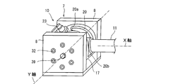
- the support 7 includes a pair of opposing plates 8 and 8 between which the spherical joint mechanism 10 is held.
- the spherical joint mechanism 10 includes a center shaft 11, and a holding mechanism 12 is attached to the tip of the center shaft 11.
- the holding mechanism 12 has a pair of blocks 14 adjustably mounted on a horizontal plate 13 extending in a lateral direction (direction orthogonal to the moving direction of the assembling apparatus), and arms forming upper and lower pairs in guide holes 15 formed in this block 14 16 is attached, and an engine W which is a work is held by these arms 16.
- the spherical joint mechanism 10 is provided with a cylindrical case 17 held between the plates 8 and 8.
- the axis (Y axis) of the cylindrical case 17 is a horizontal axis orthogonal to the Z axis.
- a spherical portion 19 formed at the base end of the center shaft 11 is rotatably accommodated in the cylindrical case 17 via a cylindrical oil-free bush 18, and the center shaft 11 is formed in the cylindrical case 17. It protrudes to the outside through the slit 20 and the holding mechanism 12 is attached to the protruding end as described above.
- An oil-free bush 21 is also provided at the base of the center shaft 11.
- the slits 20 are formed along a circumference centered on the Y axis. Therefore, the center shaft 11 is rotatable around the spherical portion 19 in a plane perpendicular to the Y axis along the slit 20. Then, in the embodiment, the positions of the end faces 20a and 20b in the circumferential direction around the Y axis of the slit 20 are determined so that the center shaft 11 can be rotated between 0 ° and 90 °. There is.
- the pivotable angle of the center shaft 11 about the Y axis is not limited to 90 °.
- Through holes 17 a and 17 b are formed in the cylindrical case 17.
- the axis of the through hole 17a coincides with the X axis, and the axis of the through hole 17b is at an angle with the X axis.
- a slit 18 a around Y axis is formed in the non-working bush 18, and a plurality of concave portions 19 a are formed in the spherical portion 19.
- the through hole 17a or 17b, the slit 18a and the recess 19a are located at specific positions of the spherical portion 19, for example, 0 °, 15 °, 30 °, 45 °, 60 °, 75 ° and 90 ° around the Z-axis.
- the axis is set to match when it becomes.
- the center shaft 11 shows a state of 0 ° around the Y axis, and in this state, the plunger 22 is inserted into the through hole 17a, the slit 18a and the recess 19a which coincide with the X axis. .
- the plunger 22 By inserting the plunger 22, the rotation of the center shaft 11 about the Y axis is blocked and locked.
- another plunger 23 is inserted into the through hole 17b not coincident with the X axis.
- the plunger 22 for blocking the rotation around the Y axis may be removed or may be left.
- clutch portions 30 are provided at both ends of the cylindrical case 17 of the spherical joint mechanism 10.
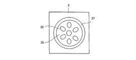
- the clutch portion 30 is provided with a plurality of guide pins 32 on the inner side surface of the side surface plate 8, and the plate 33 is engaged with these guide pins 32 so as to be movable in the Y-axis direction.
- a friction block 34 is attached to the inner surface of the plate 33.
- An inner side surface of the friction block 34 is a concave spherical surface 35 following the spherical surface portion 19, and a plurality of through holes 36 are further formed.
- a spring 37 is compressed around the guide pin 32 between the side plate 8 and the plate 33, and the resilient block of the spring 37 presses the friction block 34 attached to the plate 33 against the spherical portion 19 strongly. The rotation of the spherical portion 19 is prevented.
- a female screw hole 38 is formed in the plate 33, and a bolt 39 is screwed into the female screw hole 38.
- the bolt 39 penetrates the side plate 8 and the head of the bolt 39 is exposed to the outside doing.
- the center shaft 11 can be fixed at an arbitrary position and angle by bringing the friction block 34 into strong contact with the left and right side surfaces of the spherical portion 19.
- the position and angle of the center shaft 11 can also be fixed by inserting the plungers 22 and 23 into the through holes 17a or 17b, the slits 18a, and the recesses 19a. Fixing by the operation of the clutch unit 30 is temporary up to positioning, and is securely locked using a plunger at the time of operation.
- the center shaft 11 is fixed at a predetermined position and angle, and the work W is attached to the arm 16 of the holding mechanism 12 in this state.
- the angle around the Z axis of the center shaft 11 at the time of attachment of the work W be an angle close to 90 °, and be gradually rotated from 0 ° to 90 ° in accordance with the later work.
- the center shaft 11 may be rotated from 90 ° to 0 ° around the Y axis in view of the work procedure.
- the assembly apparatus 1 is moved along the conveyor C to the working position. Then, the support plate 5 is moved along the rail 4 to a predetermined position, and then the rotary table 3 is rotated around the Z axis, and the center shaft 11 is rotated around the Y axis, and further the center shaft 11 around the X axis. To rotate the work W to an arbitrary position and angle, and in this state, the plungers 22, 23 are inserted into the through holes 17a, 17b, the slit 18a, and the recess 19a to lock the center shaft 11; The parts are assembled to the work W or subjected to a processing operation.
- the spherical joint mechanism according to the present invention can be applied to, for example, a transfer robot as well as the assembling apparatus of the engine.
- SYMBOLS 1 assembly apparatus, 2 ... base plate, 3 ... rotary table, 4 ... rail, 5 ... support plate, 6 ... post, 7 ... support part, 8 ... plate, 10 ... spherical joint mechanism, 11 ... center shaft, 12 ...
Landscapes
- Engineering & Computer Science (AREA)
- General Engineering & Computer Science (AREA)
- Mechanical Engineering (AREA)
- Pivots And Pivotal Connections (AREA)
- Automatic Assembly (AREA)
Abstract
L'invention concerne un mécanisme de joint à rotule (10) qui comporte un boîtier cylindrique (17). L'axe du boîtier cylindrique (17) (axe y) est un axe horizontal orthogonal à l'axe z. Une partie sphérique (19) formée à l'extrémité de base d'un arbre central (11) avec un coussinet autolubrifiant cylindrique (18) interposé entre ces derniers est reçue en rotation dans le boîtier cylindrique (17). L'arbre central (11) fait saillie vers l'extérieur à travers une fente (20) formée sur le boîtier cylindrique (17). Un mécanisme de maintien (12) de pièce à travailler (W) est monté sur l'extrémité en saillie. La fente (20) est formée le long d'une périphérie centrée sur l'axe z, et l'arbre central (11) est par conséquent apte à tourner autour de la partie sphérique (19) dans un plan orthogonal à l'axe z le long de la fente (20).
Applications Claiming Priority (2)
| Application Number | Priority Date | Filing Date | Title |
|---|---|---|---|
| JP2013-094956 | 2013-04-30 | ||
| JP2013094956A JP2014214853A (ja) | 2013-04-30 | 2013-04-30 | 球面ジョイント機構及びこの球面ジョイント機構を備えた組立て装置 |
Publications (1)
| Publication Number | Publication Date |
|---|---|
| WO2014178202A1 true WO2014178202A1 (fr) | 2014-11-06 |
Family
ID=51843342
Family Applications (1)
| Application Number | Title | Priority Date | Filing Date |
|---|---|---|---|
| PCT/JP2014/050537 Ceased WO2014178202A1 (fr) | 2013-04-30 | 2014-01-15 | Mecanisme de joint a rotule et dispositif d'assemblage pourvu du mecanisme de joint a rotule |
Country Status (2)
| Country | Link |
|---|---|
| JP (1) | JP2014214853A (fr) |
| WO (1) | WO2014178202A1 (fr) |
Cited By (2)
| Publication number | Priority date | Publication date | Assignee | Title |
|---|---|---|---|---|
| CN113371355A (zh) * | 2021-02-04 | 2021-09-10 | 成都国翼电子技术有限公司 | 一种六自由度的随动抱轴装置 |
| WO2024060473A1 (fr) * | 2022-09-22 | 2024-03-28 | 中山宝益五金塑胶制品有限公司 | Structure de tête de trépied à rotule |
Families Citing this family (1)
| Publication number | Priority date | Publication date | Assignee | Title |
|---|---|---|---|---|
| CN106826759B (zh) * | 2016-12-29 | 2024-02-09 | 深圳市优必选科技有限公司 | 脚部结构及人形机器人 |
Citations (5)
| Publication number | Priority date | Publication date | Assignee | Title |
|---|---|---|---|---|
| JPS4330167Y1 (fr) * | 1964-10-12 | 1968-12-10 | ||
| JPS4821726Y1 (fr) * | 1968-06-26 | 1973-06-25 | ||
| JPS62218030A (ja) * | 1986-03-20 | 1987-09-25 | Mazda Motor Corp | ロボツトを用いた組付装置 |
| JPH0468220U (fr) * | 1990-10-24 | 1992-06-17 | ||
| JPH11159522A (ja) * | 1997-11-28 | 1999-06-15 | Nec Yonezawa Ltd | 回転自在ヒンジ機構 |
-
2013
- 2013-04-30 JP JP2013094956A patent/JP2014214853A/ja active Pending
-
2014
- 2014-01-15 WO PCT/JP2014/050537 patent/WO2014178202A1/fr not_active Ceased
Patent Citations (5)
| Publication number | Priority date | Publication date | Assignee | Title |
|---|---|---|---|---|
| JPS4330167Y1 (fr) * | 1964-10-12 | 1968-12-10 | ||
| JPS4821726Y1 (fr) * | 1968-06-26 | 1973-06-25 | ||
| JPS62218030A (ja) * | 1986-03-20 | 1987-09-25 | Mazda Motor Corp | ロボツトを用いた組付装置 |
| JPH0468220U (fr) * | 1990-10-24 | 1992-06-17 | ||
| JPH11159522A (ja) * | 1997-11-28 | 1999-06-15 | Nec Yonezawa Ltd | 回転自在ヒンジ機構 |
Cited By (2)
| Publication number | Priority date | Publication date | Assignee | Title |
|---|---|---|---|---|
| CN113371355A (zh) * | 2021-02-04 | 2021-09-10 | 成都国翼电子技术有限公司 | 一种六自由度的随动抱轴装置 |
| WO2024060473A1 (fr) * | 2022-09-22 | 2024-03-28 | 中山宝益五金塑胶制品有限公司 | Structure de tête de trépied à rotule |
Also Published As
| Publication number | Publication date |
|---|---|
| JP2014214853A (ja) | 2014-11-17 |
Similar Documents
| Publication | Publication Date | Title |
|---|---|---|
| JP5987043B2 (ja) | ワークの複数箇所を押圧するワーク固定装置 | |
| KR102368247B1 (ko) | 작업물의 제한된 영역을 처리하기 위한 장치 및 방법 | |
| JP5806310B2 (ja) | ワーク支持装置 | |
| US8157271B2 (en) | Floating chuck mechanism | |
| CN102059697A (zh) | 平移支链及使用该平移支链的并联机器人 | |
| JP2020533189A (ja) | シャフトを自動的に交換する方法およびシステム | |
| JP5546842B2 (ja) | 座標測定機械 | |
| CN107235076B (zh) | 汽车转向节及转向节定位夹紧装置 | |
| JP2014046365A (ja) | 結合装置のためのホルダ | |
| JP2014214853A (ja) | 球面ジョイント機構及びこの球面ジョイント機構を備えた組立て装置 | |
| JP5012747B2 (ja) | 部品位置決め方法および部品位置決め用治具 | |
| JP4803188B2 (ja) | デフの組立方法および組立装置 | |
| TW201529220A (zh) | 工具夾持裝置 | |
| CN111496775A (zh) | 具有可选顺应性模式的机器人工具 | |
| WO2007140591A1 (fr) | Verrou de joint universel | |
| TWM540031U (zh) | 機械手臂裝置 | |
| CN211466109U (zh) | 定位夹具组 | |
| KR101210290B1 (ko) | 매니퓰레이터 헤드 및 이를 구비하는 매니퓰레이터 | |
| JP2014079842A (ja) | 工具保持装置 | |
| JPS5946734B2 (ja) | 回転テ−ブルの姿勢変換装置 | |
| JP2023523046A (ja) | 工作機械をロボットに接続するためのクイッククランプシステム | |
| JP2011167795A (ja) | 治具 | |
| JP2023523046A5 (fr) | ||
| US12296465B2 (en) | Parallel link robot and robot system | |
| JP2018065219A (ja) | チャック装置 |
Legal Events
| Date | Code | Title | Description |
|---|---|---|---|
| 121 | Ep: the epo has been informed by wipo that ep was designated in this application |
Ref document number: 14791550 Country of ref document: EP Kind code of ref document: A1 |
|
| NENP | Non-entry into the national phase |
Ref country code: DE |
|
| 122 | Ep: pct application non-entry in european phase |
Ref document number: 14791550 Country of ref document: EP Kind code of ref document: A1 |