WO2014178255A1 - 制御装置、およびマップファイル変換装置 - Google Patents
制御装置、およびマップファイル変換装置 Download PDFInfo
- Publication number
- WO2014178255A1 WO2014178255A1 PCT/JP2014/059723 JP2014059723W WO2014178255A1 WO 2014178255 A1 WO2014178255 A1 WO 2014178255A1 JP 2014059723 W JP2014059723 W JP 2014059723W WO 2014178255 A1 WO2014178255 A1 WO 2014178255A1
- Authority
- WO
- WIPO (PCT)
- Prior art keywords
- map file
- data
- drive device
- control
- address
- Prior art date
- Legal status (The legal status is an assumption and is not a legal conclusion. Google has not performed a legal analysis and makes no representation as to the accuracy of the status listed.)
- Ceased
Links
Images


Classifications
-
- B—PERFORMING OPERATIONS; TRANSPORTING
- B60—VEHICLES IN GENERAL
- B60L—PROPULSION OF ELECTRICALLY-PROPELLED VEHICLES; SUPPLYING ELECTRIC POWER FOR AUXILIARY EQUIPMENT OF ELECTRICALLY-PROPELLED VEHICLES; ELECTRODYNAMIC BRAKE SYSTEMS FOR VEHICLES IN GENERAL; MAGNETIC SUSPENSION OR LEVITATION FOR VEHICLES; MONITORING OPERATING VARIABLES OF ELECTRICALLY-PROPELLED VEHICLES; ELECTRIC SAFETY DEVICES FOR ELECTRICALLY-PROPELLED VEHICLES
- B60L3/00—Electric devices on electrically-propelled vehicles for safety purposes; Monitoring operating variables, e.g. speed, deceleration or energy consumption
- B60L3/12—Recording operating variables ; Monitoring of operating variables
-
- B—PERFORMING OPERATIONS; TRANSPORTING
- B60—VEHICLES IN GENERAL
- B60L—PROPULSION OF ELECTRICALLY-PROPELLED VEHICLES; SUPPLYING ELECTRIC POWER FOR AUXILIARY EQUIPMENT OF ELECTRICALLY-PROPELLED VEHICLES; ELECTRODYNAMIC BRAKE SYSTEMS FOR VEHICLES IN GENERAL; MAGNETIC SUSPENSION OR LEVITATION FOR VEHICLES; MONITORING OPERATING VARIABLES OF ELECTRICALLY-PROPELLED VEHICLES; ELECTRIC SAFETY DEVICES FOR ELECTRICALLY-PROPELLED VEHICLES
- B60L15/00—Methods, circuits, or devices for controlling the traction-motor speed of electrically-propelled vehicles
- B60L15/20—Methods, circuits, or devices for controlling the traction-motor speed of electrically-propelled vehicles for control of the vehicle or its driving motor to achieve a desired performance, e.g. speed, torque, programmed variation of speed
-
- G—PHYSICS
- G06—COMPUTING OR CALCULATING; COUNTING
- G06F—ELECTRIC DIGITAL DATA PROCESSING
- G06F16/00—Information retrieval; Database structures therefor; File system structures therefor
- G06F16/10—File systems; File servers
- G06F16/11—File system administration, e.g. details of archiving or snapshots
- G06F16/116—Details of conversion of file system types or formats
-
- G—PHYSICS
- G06—COMPUTING OR CALCULATING; COUNTING
- G06F—ELECTRIC DIGITAL DATA PROCESSING
- G06F9/00—Arrangements for program control, e.g. control units
- G06F9/06—Arrangements for program control, e.g. control units using stored programs, i.e. using an internal store of processing equipment to receive or retain programs
- G06F9/44—Arrangements for executing specific programs
- G06F9/445—Program loading or initiating
- G06F9/44521—Dynamic linking or loading; Link editing at or after load time, e.g. Java class loading
-
- G—PHYSICS
- G06—COMPUTING OR CALCULATING; COUNTING
- G06F—ELECTRIC DIGITAL DATA PROCESSING
- G06F9/00—Arrangements for program control, e.g. control units
- G06F9/06—Arrangements for program control, e.g. control units using stored programs, i.e. using an internal store of processing equipment to receive or retain programs
- G06F9/44—Arrangements for executing specific programs
- G06F9/455—Emulation; Interpretation; Software simulation, e.g. virtualisation or emulation of application or operating system execution engines
- G06F9/45504—Abstract machines for programme code execution, e.g. Java virtual machine [JVM], interpreters, emulators
- G06F9/45516—Runtime code conversion or optimisation
-
- B—PERFORMING OPERATIONS; TRANSPORTING
- B60—VEHICLES IN GENERAL
- B60L—PROPULSION OF ELECTRICALLY-PROPELLED VEHICLES; SUPPLYING ELECTRIC POWER FOR AUXILIARY EQUIPMENT OF ELECTRICALLY-PROPELLED VEHICLES; ELECTRODYNAMIC BRAKE SYSTEMS FOR VEHICLES IN GENERAL; MAGNETIC SUSPENSION OR LEVITATION FOR VEHICLES; MONITORING OPERATING VARIABLES OF ELECTRICALLY-PROPELLED VEHICLES; ELECTRIC SAFETY DEVICES FOR ELECTRICALLY-PROPELLED VEHICLES
- B60L2240/00—Control parameters of input or output; Target parameters
- B60L2240/40—Drive Train control parameters
- B60L2240/42—Drive Train control parameters related to electric machines
- B60L2240/421—Speed
-
- B—PERFORMING OPERATIONS; TRANSPORTING
- B60—VEHICLES IN GENERAL
- B60L—PROPULSION OF ELECTRICALLY-PROPELLED VEHICLES; SUPPLYING ELECTRIC POWER FOR AUXILIARY EQUIPMENT OF ELECTRICALLY-PROPELLED VEHICLES; ELECTRODYNAMIC BRAKE SYSTEMS FOR VEHICLES IN GENERAL; MAGNETIC SUSPENSION OR LEVITATION FOR VEHICLES; MONITORING OPERATING VARIABLES OF ELECTRICALLY-PROPELLED VEHICLES; ELECTRIC SAFETY DEVICES FOR ELECTRICALLY-PROPELLED VEHICLES
- B60L2240/00—Control parameters of input or output; Target parameters
- B60L2240/40—Drive Train control parameters
- B60L2240/42—Drive Train control parameters related to electric machines
- B60L2240/423—Torque
-
- B—PERFORMING OPERATIONS; TRANSPORTING
- B60—VEHICLES IN GENERAL
- B60L—PROPULSION OF ELECTRICALLY-PROPELLED VEHICLES; SUPPLYING ELECTRIC POWER FOR AUXILIARY EQUIPMENT OF ELECTRICALLY-PROPELLED VEHICLES; ELECTRODYNAMIC BRAKE SYSTEMS FOR VEHICLES IN GENERAL; MAGNETIC SUSPENSION OR LEVITATION FOR VEHICLES; MONITORING OPERATING VARIABLES OF ELECTRICALLY-PROPELLED VEHICLES; ELECTRIC SAFETY DEVICES FOR ELECTRICALLY-PROPELLED VEHICLES
- B60L2250/00—Driver interactions
- B60L2250/12—Driver interactions by confirmation, e.g. of the input
-
- B—PERFORMING OPERATIONS; TRANSPORTING
- B60—VEHICLES IN GENERAL
- B60L—PROPULSION OF ELECTRICALLY-PROPELLED VEHICLES; SUPPLYING ELECTRIC POWER FOR AUXILIARY EQUIPMENT OF ELECTRICALLY-PROPELLED VEHICLES; ELECTRODYNAMIC BRAKE SYSTEMS FOR VEHICLES IN GENERAL; MAGNETIC SUSPENSION OR LEVITATION FOR VEHICLES; MONITORING OPERATING VARIABLES OF ELECTRICALLY-PROPELLED VEHICLES; ELECTRIC SAFETY DEVICES FOR ELECTRICALLY-PROPELLED VEHICLES
- B60L2250/00—Driver interactions
- B60L2250/16—Driver interactions by display
-
- Y—GENERAL TAGGING OF NEW TECHNOLOGICAL DEVELOPMENTS; GENERAL TAGGING OF CROSS-SECTIONAL TECHNOLOGIES SPANNING OVER SEVERAL SECTIONS OF THE IPC; TECHNICAL SUBJECTS COVERED BY FORMER USPC CROSS-REFERENCE ART COLLECTIONS [XRACs] AND DIGESTS
- Y02—TECHNOLOGIES OR APPLICATIONS FOR MITIGATION OR ADAPTATION AGAINST CLIMATE CHANGE
- Y02T—CLIMATE CHANGE MITIGATION TECHNOLOGIES RELATED TO TRANSPORTATION
- Y02T10/00—Road transport of goods or passengers
- Y02T10/60—Other road transportation technologies with climate change mitigation effect
- Y02T10/64—Electric machine technologies in electromobility
-
- Y—GENERAL TAGGING OF NEW TECHNOLOGICAL DEVELOPMENTS; GENERAL TAGGING OF CROSS-SECTIONAL TECHNOLOGIES SPANNING OVER SEVERAL SECTIONS OF THE IPC; TECHNICAL SUBJECTS COVERED BY FORMER USPC CROSS-REFERENCE ART COLLECTIONS [XRACs] AND DIGESTS
- Y02—TECHNOLOGIES OR APPLICATIONS FOR MITIGATION OR ADAPTATION AGAINST CLIMATE CHANGE
- Y02T—CLIMATE CHANGE MITIGATION TECHNOLOGIES RELATED TO TRANSPORTATION
- Y02T10/00—Road transport of goods or passengers
- Y02T10/60—Other road transportation technologies with climate change mitigation effect
- Y02T10/72—Electric energy management in electromobility
Definitions
- the present invention relates to control technology of a drive device that performs drive control of a motor by controlling power supplied to the motor.
- a motor such as a three-phase AC motor is mounted as a motive power source
- a driving device such as an inverter which converts direct current power supplied from a vehicle battery into alternating current power and supplies the same to the motor
- VCU Vehicle Control Unit
- the control device adjusts various command values such as a torque command to be given to the drive device according to the operation of the driver, and the drive device adjusts the power to be given to the motor according to the command value given from the control device.
- the control device acquires various data (for example, parameter information such as motor constant and data representing the current value of each phase) stored in the memory of the drive device through the above-mentioned signal line, A process of performing display control of is also performed based on those data. Thereby, the driver can be made to grasp the state of the vehicle.
- a test device such as a personal computer is connected to the drive device as the control device, and reference is made to the data stored in the memory of the drive device or the motor when the data is updated.
- Various tests such as observation of the behavior of Conventionally, when an external device such as a test apparatus accesses various data stored in the memory of the drive device, a unique function code is assigned to each data, and data desired to be read or rewritten from the memory is It is common to be realized by specifying.
- the driving device stores a table in which the function code of each data is written in association with the top address (hereinafter simply referred to as “address”) of the storage area storing each data in the memory. Keep it. Then, the function code given from the test apparatus is designated to designate data to be read or updated and is converted into an address with reference to the stored contents of the table, and the data stored in the storage area indicated by the address is The driving device is made to execute a process of reading out and returning or updating the data.
- the first point is that the work efficiency at the time of maintenance inspection is poor. Since function codes are often assigned like serial numbers, it is difficult to determine from the function code what kind of data is represented, and it is also possible to test the function code of data that you want to read or update It is also difficult for the person in charge to guess. For this reason, the tester had to conduct various tests while checking what function code is assigned to the data desired to be read or updated with reference to the manual etc. one by one.
- the second point is that it is necessary to update the table stored in each drive device each time addition, change, or deletion of the data to be read or to be updated occurs. And thirdly, there is a possibility that an excessive processing load is applied to the drive device to be subjected to maintenance inspection for conversion processing from the function code to the address, and accurate inspection can not be performed.
- the present invention has been made in view of the above problems, and can flexibly cope with addition, change, or deletion of data to be read or updated without applying an unnecessary processing load to the drive device.
- Another object of the present invention is to provide a technology that enables intuitive specification of data desired to be read or updated.
- the present invention stores a map file in a control device that controls a drive device that performs drive control of a motor according to a control program loaded in a memory, and provides the following conversion means .
- a symbol name (a character string representing a variable name) included in the source code of the control program as an identifier for loading the control program and identifying data stored in the memory of the driving device being executed.
- An address of a storage area for storing the data is written in association with.
- the conversion means causes the symbol name given as data to be read or updated to be converted to an address with reference to the map file.
- the control device of the present invention designates the data to be read or the object to be updated by the address obtained by the conversion means, and instructs the drive device to read or update the data.
- control device examples include a test device used when performing maintenance and inspection of the drive device, and an on-board controller (VCU described above).
- VCU on-board controller
- a tester when the present invention is applied to a test apparatus, a tester can specify data desired to be read or updated using a symbol name.
- a character string that can intuitively grasp the meaning of the data is often adopted as a symbol name corresponding to each data. Therefore, according to the present invention, it becomes possible to designate a data person who wants to read out or update data intuitively to a tester using intuitively understandable symbol names, and the efficiency of maintenance and inspection work is improved compared to the prior art. .
- the conversion from the symbol name to the address is executed on the control device side, so that an unnecessary processing load is not applied to the drive device.
- the map file on the control device side it is possible to flexibly cope with addition, change and deletion of data to be read or to be updated.
- each of the cited references 1 to 4 there is described a technique for associating the symbol name in the source code of the program with the address of the storage destination of the data identified by the symbol name and enabling access by the symbol name.
- the techniques disclosed in the respective documents of the cited documents 1 to 4 are not inventions relating to techniques for controlling a drive device of a motor, but are inventions different from the present invention.
- An example of a program language that describes the source code of the control program is C language.
- the C language is characterized by being able to write a program that executes processing equivalent to assembler and machine language, such as being able to realize flexible memory access by addressing, while being characterized as easier to code than assembler and machine language, control system It is often used for coding of programs.
- a structure type that is a new data type combining these existing data types is defined. It is possible to use a variable of this structure type (this variable may simply be called a “structure”).
- a variable of structure type When a variable of structure type is used in the source code of the control program, storage corresponding to the symbol name representing each of the constituent elements (hereinafter, members) of the structure is stored to store data corresponding to the member It is preferable to use a map file written with the address of the area. If such a map file is stored in the control device, it is possible to specify data to be read or to be updated in units of members of the structure.
- the map file is generated along with the executable file in the process of generating the executable file based on the source code and the header file, but in such a general map file, for variables of structure type, the variables Only the address of the storage area for storing the data of the structure in association with the symbol name of is written, and information on each member is not included. Therefore, if a general map file is used, data to be read or updated can not be specified in units of members of the structure. Therefore, there is provided a map file conversion apparatus which performs map file conversion processing on the above general map file, in which map file conversion processing is additionally performed to add the address of the storage area of data corresponding to the member in association with the symbol name of the member of the structure.
- the map file subjected to the map file conversion processing may be stored in the control device.
- the map file conversion apparatus As a specific configuration of the map file conversion apparatus, a configuration having input means for inputting various data and control means for executing map file conversion processing can be considered. That is, the source code of the control program of the drive device that performs drive control of the motor, and the definition file that defines the data type used in the source code (if the source code is described in C, the header file And the map file generated together with the control program based on the source code and the definition file are input to the map file conversion apparatus via the above input means.
- the control means refers to the definition file received via the input means and the members of the structure.
- the address obtained by adding an offset corresponding to the data type of each preceding member to the address of the storage area in which the structure is stored is associated with the symbol name of each member,
- the map file conversion processing to be added to the map file received via the input means is executed.
- the drive device stores in advance version number information indicating a version number (version) of the control program stored in the own device, and the conversion means of the control device It is characterized in that version number information is acquired from the device, and a map file corresponding to the version number indicated by the version number information is used.
- version number information is acquired from the device, and a map file corresponding to the version number indicated by the version number information is used.
- the control device stores a plurality of map files each having a different version number, and causes the conversion means to use the map file of the version number indicated by the version number information acquired from the drive device to be controlled.
- the map file itself may be used as version number information.
- control device stores in advance a control program and a map file of the version number corresponding to the control program, and the control device acquires the map file from the drive and uses it. Just do it. If the version numbers of the control program and the map file do not match, there is a possibility that the correct address can not be obtained by the conversion means, but according to this aspect, the occurrence of such inconsistency can be avoided.
- FIG. 2 is a view showing a configuration example of a test apparatus 10
- FIG. 6 is a view showing an example of the configuration of a map file conversion device 40 used to generate the map file 144b stored in the test apparatus 10. It is a figure for demonstrating the production
- FIG. 7 is a diagram showing an example of a symbol name list displayed on the display unit of the user I / F unit 120 of the test apparatus 10.
- FIG. 1 is a view showing a configuration example of a test system 1 including a test apparatus 10 of an embodiment of a control device of the present invention.
- the test system 1 is for performing maintenance and inspection of the drive device 20 mounted on the electric vehicle together with the motor 30.
- the test system 1 includes a drive device 20 to be subjected to maintenance inspection, a motor 30 driven and controlled by the drive device 20, and a control device that controls the drive device 20 in the process of performing maintenance inspection.
- a test apparatus 10 that plays the role of
- the motor 30 is a three-phase alternating current motor.
- the driving device 20 is an inverter that converts a DC power source such as a vehicle-mounted battery into three-phase AC power and supplies the same to the motor 30.
- Drive device 20 controls the current value of each phase of the three-phase AC voltage to be applied to motor 30 in accordance with various commands given from the control device (VCU in actual operation, test device 10 in the present embodiment). It includes a control unit (not shown) that executes processing in accordance with a control program installed in advance, and a memory used as a work area when executing this control program.
- the control program stored in the drive device 20 is an executable file obtained by compiling and linking the procedure of processing implemented according to the control program to source code described in a predetermined program language.
- C language is used as a program language for describing the source code.
- the C language is characterized by being able to write programs that execute processing equivalent to assembler and machine language, such as being able to realize flexible memory access by addressing, while being characterized by easier coding compared to assembler and machine language, control This is because it is suitable for coding a system program.
- the test apparatus 10 is, for example, a personal computer, and is connected to the drive device 20 via a signal line such as a twisted pair cable.
- various commands are given from the test apparatus 10 to the drive device 20 through the signal line to observe a change in the operation of the motor 30, or read data stored in the memory of the drive device 20 By checking the values, maintenance and inspection of the drive device 20 can be advanced.
- the symbol name of the external variable included in the source code of the control program is used as an identifier for identifying the data stored in the memory of the drive device 20 to read or update It differs from the prior art in that it is configured to allow a tester to specify target data.
- symbol names that can be used to intuitively understand the meaning of data are often adopted for specifying source data to be read or updated using symbol names. This is because the tester can intuitively specify the data desired to be read or updated without referring to it.
- FIG. 2 is a view showing a configuration example of the test apparatus 10.
- the test apparatus 10 includes a control unit 110, a user interface (hereinafter abbreviated as “I / F”) unit 120, a communication I / F unit 130, a storage unit 140, and data between these components. It has a bus 150 that mediates transfer.
- I / F user interface
- the control unit 110 is, for example, a CPU (Central Processing Unit).
- the control unit 110 functions as a control center of the test apparatus 10 by executing the test program 144a stored in the storage unit 140 (more precisely, the non-volatile storage unit 144).
- the user I / F unit 120 includes a display unit and an operation unit (both not shown in FIG. 2).
- the display unit is composed of a liquid crystal display and its drive circuit.
- various screens for performing maintenance and inspection of the drive device 20 are displayed under the control of the control unit 110.
- the operation unit is configured of a pointing device such as a mouse and a keyboard.
- the operation unit is for causing the tester to perform various input operations for performing maintenance and inspection of the drive device 20, and the control unit 110 controls data corresponding to the content of the operation performed on the pointing device or the like. Give to. As a result, the operation content of the person in charge of examination is transmitted to the control unit 110.
- the communication I / F unit 130 is, for example, a NIC (Network Interface Card), and is connected to the drive device 20 via a signal line such as a twisted pair cable.
- the communication I / F unit 130 sends data received from the drive unit 20 to the control unit 110 via the signal line, and transmits data provided from the control unit 110 to the drive unit 20 via the signal line. .
- the storage unit 140 includes a volatile storage unit 142 and a non-volatile storage unit 144.
- the volatile storage unit 142 is configured of, for example, a random access memory (RAM).
- the volatile storage unit 142 is used by the control unit 110 as a work area when executing the test program 144a.
- the non-volatile storage unit 144 is configured of, for example, a hard disk or a flash memory.
- a test program 144a and a map file 144b are stored in advance.
- the non-volatile storage unit 144 also stores OS software for realizing an OS (Operating System), but the illustration thereof is omitted because the relationship with the present invention is thin. .
- the control unit 110 reads OS software from the non-volatile storage unit 144 to the volatile storage unit 142 in response to the supply of power (not shown) of the test apparatus 10, and starts the execution. In this state, when instructed to execute the test program 144a via the operation unit of the user I / F unit 120, the control unit 110 reads the test program 144a from the non-volatile storage unit 144 to the volatile storage unit 142, Start its execution.
- the control unit 110 operating according to the test program 144 a causes the display unit of the user I / F unit 120 to display various screens that support the execution of the maintenance inspection of the drive device 20. Then, when a symbol name indicating data to be read or updated is input by an operation on the operation unit of user I / F unit 120, control unit 110 reads the data designated by the symbol name or updates the data. Communication is performed with the drive device 20.
- control unit 110 first uses the map file 144b to input the symbol name input to indicate the data to be read or to be updated.
- a conversion process of converting into the address of the storage area in is executed, and the address obtained by the conversion process is notified to the drive device 20 through the signal line to specify the data to be read or updated.
- the drive device 20 executes the process of reading and returning the data stored in the storage area indicated by the address notified as described above, or the process of updating the data stored in the storage area. Thus, reading or updating of data designated by the tester is realized.
- the control program is loaded into the memory in association with the symbol name of the external variable included in the source code of the control program, and the data corresponding to the symbol name is stored in the drive unit 20 being executed.
- the address of the storage area to be stored is written.
- external variables that contain source code only external variables are associated with their symbol names and addresses and written to the map file 144b because the storage area of the variables other than external variables is in the process of executing the control program. This is because the address is dynamically secured and the address associated with the symbol name is not fixed.
- the map file that associates the symbol name of the external variable contained in the source code with the address of the storage area that stores the data corresponding to the symbol name is an executable file by compiling and linking from the source code and header file Is generated along with its executable file when building.
- the map file 144b stored in the non-volatile storage unit 144 of the test apparatus 10 is not a general map file itself generated together with the control program when the control program is built, but the general map file Are obtained by performing map file conversion processing by the map file conversion apparatus 40 shown in FIG. This point is the second feature of this embodiment.
- FIG. 3 is a block diagram showing a configuration example of the map file conversion device 40.
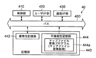
- the map file conversion device 40 is a personal computer like the test device 10, and its hardware configuration is the same as the hardware configuration of the test device 10. That is, as shown in FIG. 4, the map file conversion device 40 has a control unit 410, a user I / F unit 420, a communication I / F unit 430, a storage unit 440, and a bus that mediates data exchange between these components. It has 450.
- the storage unit 440 includes a volatile storage unit 442 and a non-volatile storage unit 444.
- the non-volatile storage unit 444 causes the control unit 410 to realize map file conversion processing that remarkably shows the features of the present embodiment.
- a map file conversion program 444a for the purpose is stored in advance.
- FIG. 4 is a diagram for explaining map file conversion processing executed by the control unit 410 according to the map file conversion program 444a. More specifically, FIG. 4A is a diagram showing an outline of the map file conversion process. As shown in FIG. 4A, in this embodiment, the source code SC of the control program (see FIG. 4B for a specific example) and the header file HF (see FIG. 4B for a specific example) Executable files from are generated by build (compile and link). The executable file is installed in the drive device 20 as a control program. Further, in the above-described build, a general map file BMF (see FIG. 4B) is generated together with the control program (executable file). In the map file BMF, the address of the storage area of the data corresponding to the external variable when the execution format file is loaded to the memory in association with the symbol name of the external variable containing the source code is written. .
- the map file BMF the address of the storage area of the data corresponding to the external variable when the execution format file is loaded to the memory
- the source code SC of the control program, the header file HF, and the map file BMF generated in the process of building the control program become input data.
- each input data is generated from the computer that has executed the build It is input to the map file conversion device 40 via the communication I / F unit 430. That is, the communication I / F unit 430 of FIG. 3 plays the role of an input unit for inputting the above input data to the map file conversion device 40.
- the map file AMF is generated by executing the map file conversion processing based on the input data, and the map file AMF is stored in the non-volatile storage unit 144 of the test apparatus 10 as the map file 144b described above. Ru.
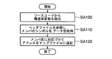
- FIG. 5 is a flowchart showing the flow of map file conversion processing.
- the control unit 410 extracts a structure type variable from external variables included in the source code input via the communication I / F unit 430.
- ADC_AD0_VALUE type this data type is defined by the header file HF
- the external variable gAD0_Value of (1) is included, the external variable g AD0_Value is extracted in the above step SA100.
- variable g AD0_Value of the ADC_AD0_VALUE type is an external variable
- the control unit 410 specifies the symbol name and data type of each member of the structure extracted in step SA100 with reference to the header file HF included in the input data (step SA110).
- the structure of ADC_AD0_VALUE type is composed of eight members of short type (mIu, mIv, mIw, mAi1, mAi2, mMAi1, mMAi2 and mVDC). These members are given names reflecting the meaning of the data stored therein. For example, data representing the u-phase current value supplied from drive device 20 to motor 30 is shown in member mIu, and data representing the v-phase current value supplied from drive device 20 to motor 30 in member mIv.
- the symbol name and data type of the member of the external variable gAD0_Value are (gAD0_Value.mIu, short), (gAD0_Value.mIv, short), (gAD0_Value.mIw, short), (gAD0_Value.mai1, short), gAD0_Value.mAi2, short), (gAD0_Value.mMAi1, short), (gAD0_Value.mmAi2, short) and (gAD0_Value.mVDC, short) are extracted.
- control unit 410 causes map file BMF input via communication I / F unit 430 to be associated with the symbol name of each member identified in step SA110 and to precede each member represented by the symbol name.
- the third member, member mIw the data type of each preceding member (member mIu and member mIv) is all short (two-byte data type), and the offset is 4.
- the map file AMF shown in FIG. 4 (b) is obtained. If the members of the structure include a char variable, so-called boundary adjustment may be performed to calculate the offset.
- the above is the flow of the map file conversion process in the map file conversion device 40.
- the map file input to the map file conversion apparatus 40 is output as the converted map file as it is. Be done.
- map file conversion processing by the map file conversion device 40 not a general map file (for example, the map file BMF in FIG. 4B) generated with the control program.
- the map file (the map file AMF in FIG. 4 (b)) is stored in the non-volatile storage unit 144 of the test apparatus 10. The reason is as follows.
- the general map file contains the top address of the storage area for storing the structure in association with the symbol name of the structure type variable, it does not contain the information on the members of the structure. Therefore, even if a general map file is stored in the test apparatus 10, data to be read or updated can not be designated by a symbol name in units of members of the structure.
- the map file AMF obtained by the above map file conversion processing is stored in the test apparatus 10 as the map file 144 b, data to be read or updated is symbolized in member units of the structure. It is possible to have a person in charge of testing designate by name.
- the map file converted by the map file conversion apparatus 40 is transferred to the test apparatus 10. I made it remember. Needless to say, if it is not necessary to specify the data to be read or to be updated in units of members of the structure, a general map file may be stored in the test apparatus 10 as the map file 144b.
- the map file subjected to the map file conversion process by the map file conversion device 40 is stored in the non-volatile storage unit 144 of the test apparatus 10.
- the tester can specify the symbol name (gAD0_Value.mIu).
- the current value of the u phase supplied from the drive unit 20 to the motor 30 can be referred to or updated.
- control unit 110 causes the control unit 110 to execute a process of displaying a list of symbol names written in the map file 144b as shown in FIG. 6, and causes the tester to select a symbol name of data desired to be read or updated. It is good. As described above, since the symbol name often reflects the meaning of the data corresponding to the symbol name, the tester instinctively desires to read or update without referring to a manual or the like. You can select the symbol name of the data. As described above, since the data desired to be read or updated can be designated by the symbol name without referring to the manual one by one, according to the present embodiment, maintenance and inspection can be performed in comparison with the prior art designated by the function code. Work efficiency is improved.
- the tester can use the symbol names to intuitively select the data desired to be read or updated among the data stored in the memory of the drive device 20. Can be specified. Further, in the present embodiment, the conversion from the symbol name to the address is performed in the test apparatus 10, and thus the drive device 20 does not have an unnecessary processing load. In addition, even when addition, change, or deletion of data to be read or to be updated occurs, it is possible to flexibly cope with the update of the map file 144b stored in the test apparatus 10.
- the test apparatus 10 is obtained by performing map file conversion processing by the map file conversion device 40 on the map file generated in the process of building the control program stored in the drive device 20.
- the map file 144b is stored. This is because the version number of the control program stored in the drive unit 20 and the version number of the map file stored in the test apparatus 10 are different (for example, used when building the control program) Of the source code and header file, the version of the source code used for generating the map file and the version of the header file differ), and the correct address may not be obtained by the symbol name / address conversion process It is from.
- the drive unit 20 stores version number information indicating the version number of the control program, while the test apparatus 10 stores the version number information in the drive unit 20. It is also possible to obtain existing version number information and use a map file corresponding to the version number indicated by the version number information.
- a plurality of map files having different version numbers are stored in the test apparatus 10, and a version indicated by version number information obtained from the drive device 20
- the control unit 110 of the test apparatus 10 causes the control unit 110 of the test apparatus 10 to execute processing for selecting and using one of the plurality of map files according to the number.
- the storage destination of the plurality of map files having different version numbers is not limited to the non-volatile storage unit 144 of the test apparatus 10, and a server apparatus (or a server apparatus that can be accessed by the test apparatus 10 via a telecommunication line such as the Internet) It may be a network compatible hard disk).
- map file obtained by subjecting the map file conversion processing by the map file conversion device 40 to the map file generated in the process of building the control program is stored in the drive device 20 as the version number information.
- version number information (map file) is acquired from the drive unit 20 prior to the start of the test (for example, upon detection of connection of the drive unit 20 via a signal line), and this map file is used. It is good.
- the present invention may be applied to a control device that communicates with the drive device 20 and performs operation control thereof during actual operation of the drive device 20.
- the present invention is applied to an on-board controller (VCU) that performs operation control of the drive unit 20 according to the driving operation of the driver of the electric vehicle. It is good.
- VCU on-board controller
- the application object of the present invention is not limited to a control device that controls a drive device for an electric vehicle, and for example, a drive device that drives a motor that raises and lowers an elevator or a drive that drives a motor of an air conditioner.
- the present invention may be applied to a control device that controls the device.
- the test program 144a that causes the control unit 110 to execute symbol name / address conversion processing that remarkably shows the features of the present invention (in other words, control as conversion means for executing symbol name / address conversion processing)
- the program for causing the unit 110 to function is stored in advance in the non-volatile storage unit of the test apparatus 10.
- the program may be written and distributed in a computer readable recording medium such as a CD-ROM (Compact Disk-Read Only Memory), or may be distributed by downloading via a telecommunication line such as the Internet. .
- a general computer device such as a personal computer according to the program distributed in this manner, it is possible to cause the computer device to function as the test device 10 of the above embodiment. .
Landscapes
- Engineering & Computer Science (AREA)
- Software Systems (AREA)
- Theoretical Computer Science (AREA)
- General Engineering & Computer Science (AREA)
- General Physics & Mathematics (AREA)
- Physics & Mathematics (AREA)
- Power Engineering (AREA)
- Transportation (AREA)
- Mechanical Engineering (AREA)
- Life Sciences & Earth Sciences (AREA)
- Sustainable Energy (AREA)
- Sustainable Development (AREA)
- Data Mining & Analysis (AREA)
- Databases & Information Systems (AREA)
- Tests Of Electronic Circuits (AREA)
- Control Of Electric Motors In General (AREA)
- Stored Programmes (AREA)
Abstract
Description
図1は、本発明の制御装置の一実施形態の試験装置10を含む試験システム1の構成例を示す図である。この試験システム1は、電動機30とともに電気自動車に搭載される駆動装置20の保守点検を行うためのものである。図1に示すように、試験システム1は、保守点検の対象となる駆動装置20と、駆動装置20により駆動制御される電動機30と、保守点検の実行過程において駆動装置20の制御を行う制御装置の役割を果たす試験装置10とを含んでいる。
(1)上記実施形態では、試験装置10には、駆動装置20に記憶されている制御プログラムのビルドの過程で生成されたマップファイルにマップファイル変換装置40によるマップファイル変換処理を施して得られたマップファイル144bが格納されていた。これは、駆動装置20に記憶されている制御プログラムの版数(バージョン)と試験装置10に記憶されているマップファイルの版数とが異なっている(例えば、制御プログラムのビルドの際に用いられたソースコードおよびヘッダファイルの版数と、マップファイルの生成に用いられたソースコードおよびヘッダファイルの版数が異なる場合など)と、シンボル名/アドレス変換処理によって正しいアドレスが得られない虞があるからである。
Claims (5)
- メモリにロードした制御プログラムにしたがって電動機の駆動制御を実行する駆動装置の制御を行う制御装置であって、
前記メモリに記憶されるデータを識別するための識別子として前記制御プログラムのソースコードに含まれているシンボル名と当該データを記憶する記憶領域のアドレスとを対応づけるマップファイルと、
読み出し対象または更新対象のデータを示すものとして与えられたシンボル名を前記マップファイルを参照してアドレスに変換する変換手段と、を有し、
前記変換手段により得られたアドレスの示す記憶領域に記憶されているデータの読み出しまたは更新を前記駆動装置に指示する
ことを特徴とする制御装置。 - 前記マップファイルには、構造体型の変数については各メンバのシンボル名に対応付けて当該メンバに対応するデータを記憶する記憶領域のアドレスが書き込まれている
ことを特徴とする請求項1に記載の制御装置。 - 前記駆動装置には、制御プログラムの版数を示す版数情報が記憶されており、
前記変換手段は、前記駆動装置に記憶されている版数情報の示す版数に対応するマップファイルを使用することを特徴とする請求項1に記載の制御装置。 - 前記駆動装置には、制御プログラムの版数を示す版数情報が記憶されており、
前記変換手段は、前記駆動装置に記憶されている版数情報の示す版数に対応するマップファイルを使用することを特徴とする請求項2に記載の制御装置。 - 入力手段と、
制御手段と、を有し、
前記制御手段は、
電動機の駆動制御を行う駆動装置の制御プログラムのソースコードと、前記ソースコードにて使用されているデータ型を定義する定義ファイルと、前記ソースコードおよび前記定義ファイルに基づいて前記制御プログラムとともに生成されたマップファイルとを前記入力手段を介して受け取り、
前記入力手段を介して受け取ったソースコードに構造体型の変数が含まれている場合には、前記入力手段を介して受け取った定義ファイルを参照して前記構造体型の変数のメンバを特定し、各メンバのシンボル名に対応付けて、先行する各メンバのデータ型に応じたオフセットを前記駆動装置において前記構造体型の変数の記憶される記憶領域のアドレスに加算して得られるアドレスを、前記入力手段を介して受け取ったマップファイルに追記するマップファイル変換処理を実行する
ことを特徴とするマップファイル変換装置。
Priority Applications (4)
| Application Number | Priority Date | Filing Date | Title |
|---|---|---|---|
| EP14791349.5A EP2993780A4 (en) | 2013-04-30 | 2014-04-02 | Controller and map file conversion device |
| JP2015514791A JP6028856B2 (ja) | 2013-04-30 | 2014-04-02 | 制御装置、およびマップファイル変換装置 |
| CN201480012244.XA CN105027425B (zh) | 2013-04-30 | 2014-04-02 | 控制装置和映射文件变换装置 |
| US14/846,929 US9751410B2 (en) | 2013-04-30 | 2015-09-07 | Controller and map file conversion device |
Applications Claiming Priority (2)
| Application Number | Priority Date | Filing Date | Title |
|---|---|---|---|
| JP2013095383 | 2013-04-30 | ||
| JP2013-095383 | 2013-04-30 |
Related Child Applications (1)
| Application Number | Title | Priority Date | Filing Date |
|---|---|---|---|
| US14/846,929 Continuation US9751410B2 (en) | 2013-04-30 | 2015-09-07 | Controller and map file conversion device |
Publications (1)
| Publication Number | Publication Date |
|---|---|
| WO2014178255A1 true WO2014178255A1 (ja) | 2014-11-06 |
Family
ID=51843390
Family Applications (1)
| Application Number | Title | Priority Date | Filing Date |
|---|---|---|---|
| PCT/JP2014/059723 Ceased WO2014178255A1 (ja) | 2013-04-30 | 2014-04-02 | 制御装置、およびマップファイル変換装置 |
Country Status (5)
| Country | Link |
|---|---|
| US (1) | US9751410B2 (ja) |
| EP (1) | EP2993780A4 (ja) |
| JP (1) | JP6028856B2 (ja) |
| CN (1) | CN105027425B (ja) |
| WO (1) | WO2014178255A1 (ja) |
Cited By (2)
| Publication number | Priority date | Publication date | Assignee | Title |
|---|---|---|---|---|
| JP2020134982A (ja) * | 2019-02-12 | 2020-08-31 | 富士電機株式会社 | 情報処理装置、情報処理方法及び情報処理システム |
| CN115544939A (zh) * | 2022-10-28 | 2022-12-30 | 中科亿海微电子科技(苏州)有限公司 | Fpga配置文件的处理方法、装置和计算机可读存储介质 |
Families Citing this family (9)
| Publication number | Priority date | Publication date | Assignee | Title |
|---|---|---|---|---|
| JP2017016503A (ja) * | 2015-07-03 | 2017-01-19 | 富士通株式会社 | コンパイラ、コンパイル装置及びコンパイル方法 |
| TWI571811B (zh) * | 2015-11-05 | 2017-02-21 | 財團法人資訊工業策進會 | 流程模型整合系統之變數定義更改裝置與方法 |
| KR20170115696A (ko) * | 2016-04-08 | 2017-10-18 | 엘에스산전 주식회사 | 인버터 시스템 |
| JP2018055654A (ja) * | 2016-09-30 | 2018-04-05 | オムロン株式会社 | 情報処理装置、情報処理方法およびプログラム |
| CN109032500B (zh) * | 2018-06-11 | 2021-12-14 | 广州视源电子科技股份有限公司 | 单片机的数据存储方法及装置、单片机、存储介质 |
| JP6823027B2 (ja) * | 2018-09-18 | 2021-01-27 | ファナック株式会社 | 数値制御装置 |
| JP7067520B2 (ja) * | 2019-03-28 | 2022-05-16 | オムロン株式会社 | 開発支援装置、開発支援装置の制御方法、情報処理プログラム、および記録媒体 |
| WO2020213059A1 (ja) * | 2019-04-16 | 2020-10-22 | 三菱電機株式会社 | プログラム作成支援装置、プログラム作成支援方法およびプログラム |
| JP7391603B2 (ja) * | 2019-10-16 | 2023-12-05 | ファナック株式会社 | 設定データ変更機能を有する制御装置及び制御装置の設定データ変更方法 |
Citations (9)
| Publication number | Priority date | Publication date | Assignee | Title |
|---|---|---|---|---|
| JPS61279906A (ja) | 1985-06-05 | 1986-12-10 | Matsushita Electric Ind Co Ltd | プログラマブルコントロ−ラ |
| JPH0546377A (ja) * | 1991-08-08 | 1993-02-26 | Hitachi Ltd | 制御プログラム作成方法及びその作成装置 |
| JP2002223586A (ja) * | 2001-01-26 | 2002-08-09 | Keyence Corp | 電動機駆動装置の動作状態解析方法及び装置 |
| JP2003061389A (ja) * | 2001-08-08 | 2003-02-28 | Keyence Corp | 電動機駆動装置における異常発生時の詳細表示方法及び電動機駆動装置 |
| JP2003061388A (ja) * | 2001-08-10 | 2003-02-28 | Keyence Corp | 電動機駆動装置のパラメータ設定方法及び電動機駆動装置 |
| JP2003070286A (ja) * | 2001-08-22 | 2003-03-07 | Keyence Corp | 文字情報の表示装置を備えた電動機駆動装置 |
| JP2003150207A (ja) | 2001-11-12 | 2003-05-23 | Toshiba Corp | プラント制御システム |
| JP2005352612A (ja) | 2004-06-08 | 2005-12-22 | Omron Corp | プログラム開発支援装置および変数名リスト表示方法 |
| JP2009245456A (ja) | 2009-07-27 | 2009-10-22 | Omron Corp | プログラム開発支援装置および処理方法 |
Family Cites Families (14)
| Publication number | Priority date | Publication date | Assignee | Title |
|---|---|---|---|---|
| JPH11338731A (ja) * | 1998-05-21 | 1999-12-10 | Oki Electric Ind Co Ltd | データ処理装置 |
| DE19836748C1 (de) * | 1998-08-13 | 2000-04-20 | Siemens Ag | Verfahren zum Applizieren von Steuerdaten eines elektronischen Kraftfahrzeug-Steuergeräts |
| US6718533B1 (en) * | 1999-02-26 | 2004-04-06 | Real-Time Innovations, Inc. | Method for building a real-time control system with mode and logical rate |
| US6854109B2 (en) * | 2001-06-07 | 2005-02-08 | International Business Machines Corporation | Tool for converting .MAP file formats |
| JP4444677B2 (ja) * | 2004-01-20 | 2010-03-31 | クラリオン株式会社 | 検索データの更新方法および更新システム |
| JP4226491B2 (ja) * | 2004-02-26 | 2009-02-18 | 株式会社ザナヴィ・インフォマティクス | 検索データの更新システムおよびナビゲーション装置 |
| JP5002140B2 (ja) * | 2005-08-24 | 2012-08-15 | クラリオン株式会社 | ナビゲーション装置およびナビゲーション処理方法 |
| US7853388B2 (en) * | 2006-02-23 | 2010-12-14 | Siemens Industry, Inc. | Devices, systems, and methods for controlling a braking system |
| US20080229165A1 (en) * | 2007-03-16 | 2008-09-18 | Etas, Inc. | Address translation system for use in a simulation environment |
| US8131765B2 (en) * | 2008-10-14 | 2012-03-06 | Lenovo (Singapore) Pte. Ltd. | Apparatus, system and method for caching writes by multiple clients to a virtualized common disk image |
| US8397222B2 (en) * | 2008-12-05 | 2013-03-12 | Peter D. Warren | Any-to-any system for doing computing |
| US8396870B2 (en) * | 2009-06-25 | 2013-03-12 | University Of Tennessee Research Foundation | Method and apparatus for predicting object properties and events using similarity-based information retrieval and modeling |
| FI124147B (fi) * | 2010-05-07 | 2014-03-31 | Abb Oy | Sähkökäyttöjärjestelmän vikadiagnostiikkajärjestely ja sähkökäyttöjärjestelmä |
| WO2014172316A1 (en) * | 2013-04-15 | 2014-10-23 | Flextronics Ap, Llc | Building profiles associated with vehicle users |
-
2014
- 2014-04-02 WO PCT/JP2014/059723 patent/WO2014178255A1/ja not_active Ceased
- 2014-04-02 CN CN201480012244.XA patent/CN105027425B/zh active Active
- 2014-04-02 JP JP2015514791A patent/JP6028856B2/ja active Active
- 2014-04-02 EP EP14791349.5A patent/EP2993780A4/en not_active Withdrawn
-
2015
- 2015-09-07 US US14/846,929 patent/US9751410B2/en active Active
Patent Citations (9)
| Publication number | Priority date | Publication date | Assignee | Title |
|---|---|---|---|---|
| JPS61279906A (ja) | 1985-06-05 | 1986-12-10 | Matsushita Electric Ind Co Ltd | プログラマブルコントロ−ラ |
| JPH0546377A (ja) * | 1991-08-08 | 1993-02-26 | Hitachi Ltd | 制御プログラム作成方法及びその作成装置 |
| JP2002223586A (ja) * | 2001-01-26 | 2002-08-09 | Keyence Corp | 電動機駆動装置の動作状態解析方法及び装置 |
| JP2003061389A (ja) * | 2001-08-08 | 2003-02-28 | Keyence Corp | 電動機駆動装置における異常発生時の詳細表示方法及び電動機駆動装置 |
| JP2003061388A (ja) * | 2001-08-10 | 2003-02-28 | Keyence Corp | 電動機駆動装置のパラメータ設定方法及び電動機駆動装置 |
| JP2003070286A (ja) * | 2001-08-22 | 2003-03-07 | Keyence Corp | 文字情報の表示装置を備えた電動機駆動装置 |
| JP2003150207A (ja) | 2001-11-12 | 2003-05-23 | Toshiba Corp | プラント制御システム |
| JP2005352612A (ja) | 2004-06-08 | 2005-12-22 | Omron Corp | プログラム開発支援装置および変数名リスト表示方法 |
| JP2009245456A (ja) | 2009-07-27 | 2009-10-22 | Omron Corp | プログラム開発支援装置および処理方法 |
Non-Patent Citations (1)
| Title |
|---|
| See also references of EP2993780A4 |
Cited By (3)
| Publication number | Priority date | Publication date | Assignee | Title |
|---|---|---|---|---|
| JP2020134982A (ja) * | 2019-02-12 | 2020-08-31 | 富士電機株式会社 | 情報処理装置、情報処理方法及び情報処理システム |
| JP7211135B2 (ja) | 2019-02-12 | 2023-01-24 | 富士電機株式会社 | 情報処理装置、情報処理方法及び情報処理システム |
| CN115544939A (zh) * | 2022-10-28 | 2022-12-30 | 中科亿海微电子科技(苏州)有限公司 | Fpga配置文件的处理方法、装置和计算机可读存储介质 |
Also Published As
| Publication number | Publication date |
|---|---|
| JPWO2014178255A1 (ja) | 2017-02-23 |
| EP2993780A4 (en) | 2017-01-11 |
| CN105027425A (zh) | 2015-11-04 |
| CN105027425B (zh) | 2018-02-13 |
| JP6028856B2 (ja) | 2016-11-24 |
| EP2993780A1 (en) | 2016-03-09 |
| US9751410B2 (en) | 2017-09-05 |
| US20150375624A1 (en) | 2015-12-31 |
Similar Documents
| Publication | Publication Date | Title |
|---|---|---|
| JP6028856B2 (ja) | 制御装置、およびマップファイル変換装置 | |
| KR101860252B1 (ko) | 작화 장치 및 제어 시스템 | |
| CN109522088A (zh) | 一种虚拟机迁移方法及装置 | |
| CN110515647A (zh) | 一种静态资源管理方法、装置、设备和存储介质 | |
| TW201217925A (en) | Logging setting device, method for setting logging, and recording medium | |
| JP5971410B2 (ja) | 制御装置および電動機の駆動装置 | |
| JP2009146229A (ja) | プログラマブルコントローラシステム | |
| JP4520466B2 (ja) | 駆動シーケンスを制御するための関数を適合させる方法および装置 | |
| JP2009217321A (ja) | 情報処理装置及び情報処理プログラム | |
| KR101632864B1 (ko) | 프로그래머블 컨트롤러 시스템, 프로그래머블 컨트롤러, 프로그램 표시장치, 프로그램의 표시 방법 | |
| CN110543113B (zh) | 机器人硬件组装及管理方法、设备、介质、系统、前端组装客户端及机器人本体运行系统 | |
| US11561520B2 (en) | Power conversion system with programming support | |
| JP5025562B2 (ja) | プログラマブルコントローラシステム | |
| JP6222369B2 (ja) | 電動機の駆動制御を行う駆動装置の試験を行うための試験装置 | |
| JP2016001825A (ja) | 通信試験装置、および検証作業支援方法 | |
| CN104106015A (zh) | 可编程控制器系统、其可编程显示器、辅助装置、程序 | |
| JP5627506B2 (ja) | データ処理装置 | |
| CN120409051B (zh) | 通过xcp协议将fmu模型部署到实时目标机进行实时参数标定和数据采集的方法、装置及其可读存储介质 | |
| JP2023013482A (ja) | 管理装置、及び、材料試験機の管理システム | |
| WO2023115397A1 (zh) | 生成自动化脚本的方法和装置 | |
| JP7241982B1 (ja) | 画像生成プログラム、画像生成装置、プログラマブルコントローラシステム及び画像生成方法 | |
| JP2006011950A (ja) | インストーラ作成装置及びその方法、そのプログラム | |
| JP4655522B2 (ja) | 電動パワーステアリング装置のための制御定数設計適合装置 | |
| EP4254108A1 (en) | Operating assistance system and operating assistance method | |
| WO2016016992A1 (ja) | 電動機の駆動制御を行う駆動装置の試験を行うための試験装置 |
Legal Events
| Date | Code | Title | Description |
|---|---|---|---|
| WWE | Wipo information: entry into national phase |
Ref document number: 201480012244.X Country of ref document: CN |
|
| 121 | Ep: the epo has been informed by wipo that ep was designated in this application |
Ref document number: 14791349 Country of ref document: EP Kind code of ref document: A1 |
|
| WWE | Wipo information: entry into national phase |
Ref document number: 2014791349 Country of ref document: EP |
|
| ENP | Entry into the national phase |
Ref document number: 2015514791 Country of ref document: JP Kind code of ref document: A |
|
| NENP | Non-entry into the national phase |
Ref country code: DE |