WO2014178286A1 - 送信装置、送信方法、受信装置および受信方法 - Google Patents
送信装置、送信方法、受信装置および受信方法 Download PDFInfo
- Publication number
- WO2014178286A1 WO2014178286A1 PCT/JP2014/060877 JP2014060877W WO2014178286A1 WO 2014178286 A1 WO2014178286 A1 WO 2014178286A1 JP 2014060877 W JP2014060877 W JP 2014060877W WO 2014178286 A1 WO2014178286 A1 WO 2014178286A1
- Authority
- WO
- WIPO (PCT)
- Prior art keywords
- video data
- level
- transmission
- input video
- information
- Prior art date
- Legal status (The legal status is an assumption and is not a legal conclusion. Google has not performed a legal analysis and makes no representation as to the accuracy of the status listed.)
- Ceased
Links
Images














Classifications
-
- H—ELECTRICITY
- H04—ELECTRIC COMMUNICATION TECHNIQUE
- H04N—PICTORIAL COMMUNICATION, e.g. TELEVISION
- H04N5/00—Details of television systems
- H04N5/38—Transmitter circuitry for the transmission of television signals according to analogue transmission standards
-
- H—ELECTRICITY
- H04—ELECTRIC COMMUNICATION TECHNIQUE
- H04N—PICTORIAL COMMUNICATION, e.g. TELEVISION
- H04N19/00—Methods or arrangements for coding, decoding, compressing or decompressing digital video signals
- H04N19/46—Embedding additional information in the video signal during the compression process
-
- H—ELECTRICITY
- H04—ELECTRIC COMMUNICATION TECHNIQUE
- H04N—PICTORIAL COMMUNICATION, e.g. TELEVISION
- H04N19/00—Methods or arrangements for coding, decoding, compressing or decompressing digital video signals
- H04N19/70—Methods or arrangements for coding, decoding, compressing or decompressing digital video signals characterised by syntax aspects related to video coding, e.g. related to compression standards
-
- H—ELECTRICITY
- H04—ELECTRIC COMMUNICATION TECHNIQUE
- H04N—PICTORIAL COMMUNICATION, e.g. TELEVISION
- H04N19/00—Methods or arrangements for coding, decoding, compressing or decompressing digital video signals
- H04N19/85—Methods or arrangements for coding, decoding, compressing or decompressing digital video signals using pre-processing or post-processing specially adapted for video compression
-
- H—ELECTRICITY
- H04—ELECTRIC COMMUNICATION TECHNIQUE
- H04N—PICTORIAL COMMUNICATION, e.g. TELEVISION
- H04N21/00—Selective content distribution, e.g. interactive television or video on demand [VOD]
- H04N21/20—Servers specifically adapted for the distribution of content, e.g. VOD servers; Operations thereof
- H04N21/23—Processing of content or additional data; Elementary server operations; Server middleware
- H04N21/236—Assembling of a multiplex stream, e.g. transport stream, by combining a video stream with other content or additional data, e.g. inserting a URL [Uniform Resource Locator] into a video stream, multiplexing software data into a video stream; Remultiplexing of multiplex streams; Insertion of stuffing bits into the multiplex stream, e.g. to obtain a constant bit-rate; Assembling of a packetised elementary stream
- H04N21/23614—Multiplexing of additional data and video streams
-
- H—ELECTRICITY
- H04—ELECTRIC COMMUNICATION TECHNIQUE
- H04N—PICTORIAL COMMUNICATION, e.g. TELEVISION
- H04N21/00—Selective content distribution, e.g. interactive television or video on demand [VOD]
- H04N21/40—Client devices specifically adapted for the reception of or interaction with content, e.g. set-top-box [STB]; Operations thereof
- H04N21/43—Processing of content or additional data, e.g. demultiplexing additional data from a digital video stream; Elementary client operations, e.g. monitoring of home network or synchronising decoder's clock; Client middleware
- H04N21/431—Generation of visual interfaces for content selection or interaction; Content or additional data rendering
- H04N21/4318—Generation of visual interfaces for content selection or interaction; Content or additional data rendering by altering the content in the rendering process, e.g. blanking, blurring or masking an image region
-
- H—ELECTRICITY
- H04—ELECTRIC COMMUNICATION TECHNIQUE
- H04N—PICTORIAL COMMUNICATION, e.g. TELEVISION
- H04N21/00—Selective content distribution, e.g. interactive television or video on demand [VOD]
- H04N21/40—Client devices specifically adapted for the reception of or interaction with content, e.g. set-top-box [STB]; Operations thereof
- H04N21/43—Processing of content or additional data, e.g. demultiplexing additional data from a digital video stream; Elementary client operations, e.g. monitoring of home network or synchronising decoder's clock; Client middleware
- H04N21/434—Disassembling of a multiplex stream, e.g. demultiplexing audio and video streams, extraction of additional data from a video stream; Remultiplexing of multiplex streams; Extraction or processing of SI; Disassembling of packetised elementary stream
- H04N21/4348—Demultiplexing of additional data and video streams
-
- H—ELECTRICITY
- H04—ELECTRIC COMMUNICATION TECHNIQUE
- H04N—PICTORIAL COMMUNICATION, e.g. TELEVISION
- H04N21/00—Selective content distribution, e.g. interactive television or video on demand [VOD]
- H04N21/80—Generation or processing of content or additional data by content creator independently of the distribution process; Content per se
- H04N21/83—Generation or processing of protective or descriptive data associated with content; Content structuring
- H04N21/84—Generation or processing of descriptive data, e.g. content descriptors
-
- H—ELECTRICITY
- H04—ELECTRIC COMMUNICATION TECHNIQUE
- H04N—PICTORIAL COMMUNICATION, e.g. TELEVISION
- H04N5/00—Details of television systems
- H04N5/44—Receiver circuitry for the reception of television signals according to analogue transmission standards
- H04N5/57—Control of contrast or brightness
-
- H—ELECTRICITY
- H04—ELECTRIC COMMUNICATION TECHNIQUE
- H04N—PICTORIAL COMMUNICATION, e.g. TELEVISION
- H04N7/00—Television systems
- H04N7/08—Systems for the simultaneous or sequential transmission of more than one television signal, e.g. additional information signals, the signals occupying wholly or partially the same frequency band, e.g. by time division
-
- H—ELECTRICITY
- H04—ELECTRIC COMMUNICATION TECHNIQUE
- H04N—PICTORIAL COMMUNICATION, e.g. TELEVISION
- H04N9/00—Details of colour television systems
- H04N9/64—Circuits for processing colour signals
- H04N9/641—Multi-purpose receivers, e.g. for auxiliary information
-
- H—ELECTRICITY
- H04—ELECTRIC COMMUNICATION TECHNIQUE
- H04N—PICTORIAL COMMUNICATION, e.g. TELEVISION
- H04N9/00—Details of colour television systems
- H04N9/64—Circuits for processing colour signals
- H04N9/68—Circuits for processing colour signals for controlling the amplitude of colour signals, e.g. automatic chroma control circuits
- H04N9/69—Circuits for processing colour signals for controlling the amplitude of colour signals, e.g. automatic chroma control circuits for modifying the colour signals by gamma correction
-
- H—ELECTRICITY
- H04—ELECTRIC COMMUNICATION TECHNIQUE
- H04N—PICTORIAL COMMUNICATION, e.g. TELEVISION
- H04N23/00—Cameras or camera modules comprising electronic image sensors; Control thereof
- H04N23/70—Circuitry for compensating brightness variation in the scene
- H04N23/741—Circuitry for compensating brightness variation in the scene by increasing the dynamic range of the image compared to the dynamic range of the electronic image sensors
Definitions
- the present technology relates to a transmission device, a transmission method, a reception device, and a reception method, and more particularly, to a transmission device that transmits transmission video data obtained by applying a gamma curve.
- Enhance the realism of high image quality by increasing the simultaneous reproduction capability of the lowest luminance level and highest luminance level when displaying images. This simultaneous reproduction capability is sometimes called display dynamic range.
- a white luminance value of 100 cd / m2 was basically used from camera shooting to monitor display.
- 8-bit transmission (0 to 255 gradations that can be expressed) has been assumed.
- the number of gradations that can be expressed can be expanded by performing transmission using 10 bits or more.
- gamma correction for correcting the gamma characteristic of a display by inputting data having characteristics opposite to those of the display is known.
- Non-Patent Document 1 is generated by encoding transmission video data obtained by applying a gamma curve to input video data having a level of 0 to 100% * N (N is greater than 1). For example, transmitting a video stream is described.
- High Efficiency Video Coding (HEVC) text specification draft 10 for FDIS & Last Call
- the purpose of this technology is to enable display with an appropriate luminance dynamic range on the receiving side.
- the concept of this technology is A processing unit for obtaining transmission video data by applying a gamma curve to input video data having a level range of 0% to 100% * N (N is a number greater than 1);
- the transmission apparatus includes a transmission unit that transmits the transmission video data together with auxiliary information for converting a high luminance level on the reception side.
- transmission video data is obtained by applying a gamma curve to input video data having a level range of 0% to 100% * N (N is a number greater than 1) by the processing unit.
- the transmission unit transmits transmission video data together with auxiliary information for converting a high luminance level on the reception side.
- the transmission unit includes an auxiliary information insertion unit that transmits a container of a predetermined format including a video stream obtained by encoding transmission video data, and inserts auxiliary information into the video stream layer and / or the container layer. , May be.
- the processing unit further outputs a level corresponding to a level of 100% to 100% * N of the input video data with respect to the output video data obtained by applying a gamma curve to the input video data.
- Transmission video data may be obtained by performing processing for conversion to a level corresponding to 100% of input video data.
- the auxiliary information may include information on a filter to be applied to pixel data at a level corresponding to 100% of the input video data of the transmission video data.
- the processing unit further outputs 100 of the input video data from a threshold value equal to or less than a level corresponding to 100% of the input video data, with respect to the output video data obtained by applying the gamma curve to the input video data.
- Transmission video data may be obtained by performing a process of converting a level corresponding to% * N to a level between a threshold and a level corresponding to 100% of the input video data.
- the auxiliary information may include information on a filter applied to pixel data from a threshold value of transmission video data to a level corresponding to 100% of input video data.
- the auxiliary information may include information on a conversion curve applied to pixel data from a threshold value of transmission video data to a level corresponding to 100% of input video data.
- the processing unit may be configured such that output video data obtained by applying a gamma curve to input video data is used as transmission video data as it is.
- the auxiliary information may include information on a conversion curve applied to the high level side of the transmission video data.
- transmission video data obtained by applying a gamma curve to input video data having a level range of 0% to 100% * N is used to convert a high luminance level on the receiving side. It is transmitted with auxiliary information. Therefore, on the receiving side, it is possible to convert the high luminance level of the transmission video data by this auxiliary information.
- low dynamic range transmission video data having a level corresponding to 100% of the input video data as the maximum level can be converted so that the maximum level becomes high, and high dynamic range video data can be obtained. It becomes. Further, for example, in transmission video data having a high dynamic range having a level corresponding to 100% * N of the input video data as a maximum level, the video data having a low dynamic range is converted by converting the maximum level to a low level. Can be obtained. Therefore, for example, display with an appropriate luminance dynamic range is possible on the receiving side.
- an identification information insertion unit that inserts identification information indicating that auxiliary information is inserted into the layer of the video stream into the layer of the container may be provided.
- the receiving side can know that auxiliary information is inserted into the video stream without decoding the video stream, and can appropriately extract the auxiliary information from the video stream.
- a receiving apparatus includes a processing unit that converts a level range on the high level side of the transmission video data based on auxiliary information received together with the transmission video data so that the maximum level becomes a predetermined level.
- transmission video data is received by the receiving unit.
- This transmission video data is obtained by applying a gamma curve to input video data having a level range of 0% to 100% * N (N is a number greater than 1).
- the processing unit converts the level range on the high level side of the transmission video data based on the auxiliary information received together with the transmission video data so that the maximum level becomes a predetermined level.
- the processing unit may determine the predetermined level based on the N information included in the auxiliary information and the information on the luminance dynamic range of the monitor. Further, for example, the receiving unit receives a container in a predetermined format including a video stream obtained by encoding transmission video data. The auxiliary information is inserted in the layer of the video stream, for example.
- the transmission video data has a level corresponding to a level of 100% to 100% * N of the input video data with respect to the output video data obtained by applying a gamma curve to the input video data.
- Video data obtained by performing a process of converting to a level corresponding to 100% of the input video data and the processing unit converts each pixel data of a level corresponding to 100% of the input video data of the transmission video data.
- the level may be converted to a level between a level corresponding to 100% of the input video data and a predetermined level by applying a filter specified by the filter information included in the auxiliary information.
- transmission video data is further compared to output video data obtained by applying a gamma curve to input video data, from a threshold value equal to or lower than a level corresponding to 100% of the input video data.
- This is video data obtained by performing processing for converting a level corresponding to 100% * N to a level between a threshold and a level corresponding to 100% of the input video data.
- the level of each pixel data from the threshold value to a level corresponding to 100% of the input video data is applied to a level between the threshold value and a predetermined level by applying a filter specified by the filter information included in the auxiliary information. May be converted.
- transmission video data is further compared to output video data obtained by applying a gamma curve to input video data, from a threshold value equal to or lower than a level corresponding to 100% of the input video data.
- This is video data obtained by performing processing for converting a level corresponding to 100% * N to a level between a threshold and a level corresponding to 100% of the input video data.
- Each pixel data from the threshold value to a level corresponding to 100% of the input video data is converted to a level between the threshold value and a predetermined level by applying conversion curve information included in the auxiliary information. May be.
- the transmission video data is the video data as is of the output video data obtained by applying the gamma curve to the input video data
- the processing unit converts the transmission video data to 100% of the input video data. Applying the conversion curve information included in the auxiliary information to each pixel data of a level corresponding to 100% * N of the input video data from a threshold value equal to or lower than the corresponding level, L * 100% (L May be converted into a level up to a level corresponding to a number equal to or less than N).
- transmission video data obtained by applying a gamma curve to input video data having a level range of 0% to 100% * N is received, and the high level side level of the transmission video data is received.
- the range is converted so that the maximum level becomes a predetermined level based on the auxiliary information received together with the transmission video data. Therefore, for example, display with an appropriate luminance dynamic range is possible.
- FIG. 3 is a block diagram illustrating a configuration example of a transmission device 100.
- FIG. It is a figure which shows the access unit of the head of GOP in case an encoding system is HEVC. It is a figure which shows access units other than the head of GOP in case an encoding system is HEVC. It is a figure which shows the structural example of a tone mapping information SEI message. It is a figure which shows the structural example of a tone mapping information SEI message.
- FIG. 1 is a block diagram illustrating a configuration example of an MPEG-DASH-based stream distribution system.
- FIG. It is a figure which shows an example of the relationship of each structure arrange
- It is a block diagram which shows the structural example of the transmission / reception system which handles a MMT structure transmission stream. It is a figure which shows the structure of an MMT packet in a tree format.
- FIG. 1 shows a configuration example of a transmission / reception system 10 as an embodiment.
- the transmission / reception system 10 includes a transmission device 100 and a reception device 200.
- the transmission device 100 generates an MPEG2 transport stream TS as a container, and transmits the transport stream TS on a broadcast wave.
- This transport stream TS has a video stream obtained by encoding transmission video data obtained by applying a gamma curve.
- the transmission video data is, for example, HDR (High Dynamic Range) input video data obtained by being imaged by a camera, that is, a level range of 0 to 100% * N (N is a number greater than 1). This is obtained by applying a gamma curve to input video data having.
- a level of 100% is premised on a luminance level corresponding to a white luminance value of 100 cd / m 2.
- Transmission video data is, for example, the following transmission video data (a), transmission video data (b), transmission video data (c), and the like.
- the transmission video data (a) and the transmission video data (b) have a level corresponding to 100% of the input video data as the maximum level, and take the form of video data with a low dynamic range.
- the transmission video data (c) has a level corresponding to the level of 100% * N of the input video data as the maximum level, and takes the form of video data with a high dynamic range.
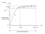
- Transmission video data (a) The transmission video data (a) will be described with reference to FIG.
- Content data level range indicates a level range from 0% to 100% * N of the input video data.
- V_100 * N indicates a level of video data (output video data) after applying the gamma curve, which corresponds to a level of 100% * N of the input video data.
- V_100 indicates the level of video data (output video data) after applying the gamma curve, which corresponds to a level of 100% of the input video data.
- Encoder Input Pixel data range indicates a level range from 0 to V_100 of transmission video data. For example, the number of gradations from 0 to V_100 is represented by a predetermined bit, for example, 8 bits.
- the transmission video data (a) further corresponds to a level of 100% to 100% * N of the input video data with respect to the output video data obtained by applying a gamma curve (see solid line a) to the input video data. It is obtained by performing a clipping process (see broken line b) for converting the level to a level (V_100) corresponding to 100% of the input video data.
- the transmission video data (a) has a level corresponding to a level of 0% to 100% of the input video data, and takes the form of low dynamic range video data.
- Transmission video data (b) The transmission video data (b) will be described with reference to FIG. “Content data level range”, “V_100 * N”, and “Encoder Input Pixel data range” are the same as those in FIG. “V_th” indicates a threshold clipping level (Threshold_clipping_level) which is a threshold value equal to or lower than a level corresponding to 100% of the input video data.
- Theshold_clipping_level is a threshold value equal to or lower than a level corresponding to 100% of the input video data.
- the transmission video data (b) has a threshold value (V_th) equal to or lower than the level corresponding to 100% of the input video data with respect to the output video data obtained by applying the gamma curve (see solid line a) to the input video data.
- V_th a threshold value
- This transmission video data (b) has a level corresponding to a level from 0% to 100% of the input video data, and takes the form of video data with a low dynamic range.
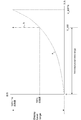
- Transmission video data (c) The transmission video data (c) will be described with reference to FIG. “Content data level range” and “V_100 * N” are the same as those in FIG. “Encoder Input Pixel data range” indicates a level range of 0 to V_100 * N of transmission video data.
- the transmission video data (c) is output video data obtained by applying a gamma curve (see solid line a) to the input video data.
- This transmission video data (c) has a level corresponding to a level of 0% to 100% * N of the input video data, and takes the form of high dynamic range video data.
- the transmission device 100 inserts the above-described gamma curve information into the video stream layer.
- this information includes “extended_range_white_level”, “nominal_black_level_code_value”, “nominal_white_level_code_value”, “extended_white_level_code_value”, and the like.
- “Extended_range_white_level” indicates a percentage (100% * N) of an integer multiple (N times) when “nominal white level” is 100%.
- “Nominal_black_level_code_value” indicates a luminance sample value with respect to the standard black level. When video data is encoded with 8 bits, the black level is set to “16”.
- “Nominal_white_level_code_value” indicates a luminance sample value with respect to the standard white level. When video data is encoded with 8 bits, the white level is set to “235”, for example.
- “Extended_white_level_code_value” indicates a luminance sample value of “extended_range_white_level”.
- the transmitting apparatus 100 inserts auxiliary information for converting the level range on the high level side of the transmission video data on the receiving side into the layer of the video stream.
- This auxiliary information includes filter information, conversion curve information, and the like. Details of this auxiliary information will be described later.
- the transmission device 100 inserts identification information indicating that gamma curve information and auxiliary information are inserted into the layer of the video stream into the layer of the transport stream TS.
- this identification information is inserted under a program map table (PMT: Program Map Table) included in the transport stream TS. Based on the identification information, it is possible to know whether or not gamma curve information or auxiliary information has been inserted without decoding the video stream. Details of this identification information will be described later.
- PMT Program Map Table
- the receiving device 200 receives the transport stream TS transmitted from the transmitting device 100 on a broadcast wave.
- the transport stream TS has a video stream including encoded video data.
- the receiving apparatus 200 acquires video data for display by performing processing such as decoding of a video stream.
- Gamma curve information and auxiliary information are inserted into the video stream layer as described above. Also, identification information indicating whether or not gamma curve information or auxiliary information is inserted into the video stream layer is inserted into the transport stream TS layer. Based on this identification information, the receiving apparatus 200 recognizes that gamma curve information and auxiliary information are inserted in the layer of the video stream, acquires these information from the video stream, and uses them for processing.
- the receiving apparatus 200 converts the high-level level range of the decoded video data (transmission video data) so that the maximum level becomes a predetermined level based on the auxiliary information.
- the receiving apparatus 200 determines the predetermined level based on, for example, N information included in the auxiliary information and information on the luminance dynamic range of the monitor.
- the reception device 200 When the transmission video data is the transmission video data (a), the transmission video data (b), or the transmission video data (c), the reception device 200 performs a conversion process as described below. By this conversion processing, it is possible to display with an appropriate luminance dynamic range on the receiving side.
- “Decoded pixel data range” indicates a level range from 0 to V_100 of input video data (transmission video data).
- “Display Level range” indicates a level range from 0% luminance to 100% * N luminance of the monitor (display).
- the solid line a is a curve indicating the gamma characteristic of the monitor, and is the reverse of the above-described gamma curve (see the solid line a in FIG. 2).
- the receiving apparatus 200 applies the filter specified by the filter information included in the auxiliary information to the level of each pixel data of the transmission video data whose level is V_100, from V_100 to a predetermined level (V_100 * N or less). Convert between levels.
- pixel data at the level of V_100 is converted to a level that generates 100% or more luminance on the monitor (display), as indicated by a dashed line b.
- the converted video data has a predetermined level higher than V_100 as the maximum level, and becomes video data with a high dynamic range.
- “Decoded pixel data range” indicates a level range from 0 to V_100 of input video data (transmission video data).
- “Display Level range” indicates a level range from 0% luminance to 100% * N luminance of the monitor (display).
- the solid line a is a curve indicating the gamma characteristic of the monitor, and is the reverse of the above-described gamma curve (see the solid line a in FIG. 3).
- the receiving apparatus 200 applies the filter information or the conversion curve information included in the auxiliary information to the level of each pixel data of the transmission video data from V_th to V_100, and applies a predetermined level (V_100 * N or less) from V_th Convert to a level between.
- pixel data of a level from V_th to V_100 in the transmission video data before conversion is converted to a level that generates 100% or more luminance on the monitor (display), as indicated by a dashed line b.
- the converted video data has a predetermined level higher than V_100 as the maximum level, and becomes video data with a high dynamic range.
- FIG. 8 shows an example of the relationship between the luminance sample value and the pixel frequency (frequency) in the video data.
- FIG. 8A shows the state of input video data in the transmission apparatus 100, and the maximum sample value is V_N * 100.
- FIG. 8B shows the state of transmission video data (output video data) after applying the gamma curve in the transmission apparatus 100, and the maximum sample value is suppressed to V_100.
- the pixel of the sample value in the range indicated by the broken line is affected by the mapping process, and deviates from the original level.
- FIG. 8C shows a state after the conversion process in the receiving apparatus 200.
- the pixels existing in the sample values in the range indicated by the broken line have been subjected to conversion processing (remapping processing).
- conversion processing remapping processing
- the level of each pixel affected by the mapping process is brought closer to the level before the mapping process.
- the maximum sample value is V_N * 100.
- the maximum sample value is set to a level smaller than V_N * 100.
- “Decoded pixel data range” indicates a level range from 0 to V_100 * N of input video data (transmission video data).
- “Display Level range” indicates a level range from 0% luminance to 100% * L luminance of the monitor (display).
- a solid line a is a curve indicating the gamma characteristic of the monitor, and is a characteristic opposite to the above-described gamma curve (see the solid line a in FIG. 4).
- the receiving apparatus 200 applies the conversion curve information included in the auxiliary information to the level of each pixel data of the transmission video data from V_th to V_100 * N, and between V_th and a predetermined level (V_100 * L). Convert to level.
- pixel data of a level from V_th to V_100 * N is converted to a level that generates a luminance of 100 * L or less on the monitor (display) as shown by a dashed line b. Is done.
- the converted video data has a predetermined level lower than V_100 * N as the maximum level, and becomes video data with a low dynamic range.
- FIG. 10 illustrates a configuration example of the transmission device 100.
- the transmission apparatus 100 includes a control unit 101, a camera 102, a color space conversion unit 103, a gamma processing unit 104, a video encoder 105, a system encoder 106, and a transmission unit 107.
- the control unit 101 includes a CPU (Central Processing Unit), and controls the operation of each unit of the transmission device 100 based on a control program stored in a predetermined storage.
- CPU Central Processing Unit
- the camera 102 images a subject and outputs HDR (High Dynamic Range) video data.
- This video data has a level of 0 to 100% * N, for example, 0 to 400% or 0 to 800%.
- the level of 100% corresponds to a white luminance value of 100 cd / m2.
- the color space conversion unit 103 converts the video data output from the camera 102 from the RGB color space to the YUV color space.
- the gamma processing unit 104 applies a gamma curve to the video data after color space conversion, and further performs processing (mapping processing, clipping processing) for converting a high-luminance level as necessary to transmit the transmission video data. (See FIGS. 2 to 4).
- the transmission video data is represented by 8 bits in the case of transmission video data (a) and (b), and is represented by 9 bits or more in the case of transmission video data (c).
- the video encoder 105 performs encoding such as MPEG4-AVC, MPEG2 video, or HEVC (high Efficiency Video Coding) on the converted video data to obtain encoded video data. Further, the video encoder 105 generates a video stream (video elementary stream) including the encoded video data by a stream formatter (not shown) provided in the subsequent stage.
- encoding such as MPEG4-AVC, MPEG2 video, or HEVC (high Efficiency Video Coding) on the converted video data to obtain encoded video data. Further, the video encoder 105 generates a video stream (video elementary stream) including the encoded video data by a stream formatter (not shown) provided in the subsequent stage.
- the video encoder 105 inserts gamma curve information and auxiliary information into the layer of the video stream.
- This auxiliary information is information for converting a high luminance level on the receiving side, and includes filter information, conversion curve information, and the like.
- the system encoder 106 generates a transport stream TS including the video stream generated by the video encoder 105. Then, the transmitting unit 107 transmits this transport stream TS to the receiving apparatus 200 on a broadcast wave or a net packet.
- the system encoder 106 inserts identification information indicating whether or not gamma curve information or auxiliary information is inserted into the layer of the video stream into the layer of the transport stream TS. Further, the system encoder 106 further inserts conversion curve data in the layer of the transport stream TS. For example, the system encoder 106 inserts identification information and conversion curve data under a video elementary loop (Video ES loop) of a program map table (PMT: Program Map Table) included in the transport stream TS. .
- PMT Program Map Table
- HDR video data obtained by imaging with the camera 102 is converted from the RGB color space to the YUV color space by the color space conversion unit 103 and then supplied to the gamma processing unit 104.
- a gamma curve is applied to the video data after color space conversion, and further, processing (mapping processing, clipping processing) for converting a high luminance level is performed as necessary, and transmission video data Is obtained.
- This transmission video data is supplied to the video encoder 105.
- the video encoder 105 performs encoding such as MPEG4-AVC (MVC), MPEG2 video, or HEVC (high Efficiency Video Coding) on the transmission video data to obtain encoded video data.
- the video encoder 105 generates a video stream (video elementary stream) including the encoded video data.
- the video encoder 105 inserts gamma curve information into the layer of the video stream and also inserts auxiliary information including filter information and conversion curve information for converting a high luminance level on the receiving side.
- the video stream generated by the video encoder 105 is supplied to the system encoder 106.
- the system encoder 106 generates an MPEG2 transport stream TS including a video stream.
- the system encoder 106 inserts identification information indicating that gamma curve information and auxiliary information are inserted into the layer of the video stream, and further conversion curve data into the layer of the transport stream TS.
- the transport stream TS is transmitted on a broadcast wave by the transmission unit 107 and transmitted.
- gamma curve information and auxiliary information are inserted into the layer of the video stream.
- the auxiliary information is stored in the access unit (AU) “ The SEI message is inserted as a SEI message.
- Gamma curve information is inserted as tone mapping information SEI message (Tone mapping information SEI message). Further, the auxiliary information is inserted as an HDR / conversion / SEI message (HDR conversion SEI message).
- FIG. 11 shows the top access unit of GOP (Group Of Pictures) when the encoding method is HEVC.
- FIG. 12 shows access units other than the head of GOP (Group Of Pictures) when the encoding method is HEVC.
- a decoding SEI message group “Prefix_SEIs” is arranged before a slice (slices) in which pixel data is encoded, and a display SEI message group “ “Suffix_SEIs” is arranged.
- the tone mapping information SEI message (Tone mapping information SEI message) and the HDR conversion SEI message (HDR conversion SEI message) are arranged as a SEI message group “Suffix_SEIs”. .
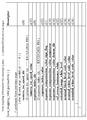
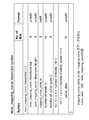
- FIG. 13 and FIG. 14 show a structural example (Syntax) of “Tone mapping information SEI message”.
- FIG. 15 shows the contents (Semantics) of main information in the structural example.
- “Tone mapping_cancel_flag” is 1-bit flag information. “1” indicates that the message state of the previous tone mapping ((Tone mapping) is cancelled. “0” indicates that each element is transmitted and the previous state is refreshed.
- coded_data_bit_depth indicates the bit length of the encoded data, and for example, 8 to 14 bits are used.
- “Target_bit_depth” indicates the maximum bit length assumed as the output (output) bit length of processing by the tone mapping information SEI message, and can take up to 16 bits.
- ref_screen_luminance_white indicates the standard white level of the reference monitor, and its unit is "cd / m2.”
- Extended_range_white_level indicates a percentage (100% * N) of an integer multiple (N times) where “nominal white level (standard white level)” is 100%.
- Nominal_black_level_code_value indicates a luminance sample value with respect to the standard black level. When video data is encoded with 8 bits, the black level is set to “16”.
- “Nominal_white_level_code_value” indicates a luminance sample value with respect to the standard white level. When video data is encoded with 8 bits, the white level is set to “235”.
- Extended_white_level_code_value indicates a luminance sample value of “extended_range_white_level”.
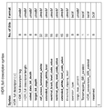
- FIG. 16 shows a structural example (Syntax) of “HDR_conversion SEI message”.
- FIG. 17 shows the contents (Semantics) of main information in the structural example.
- “HDR_conversion_cancel_flag” is 1-bit flag information. “1” indicates that the previous message state of HDR conversion (HDR_conversion) is canceled. “0” indicates that each element is transmitted, so that the previous state is refreshed.
- the 16-bit field of “threshold_clipping_level” indicates the threshold value of luminance, that is, V_th, which is converted into the conventional encoding range by non-linear tone mapping in the HDR range (see FIG. 3).
- the 8-bit field of “operator_type” indicates a filter type used when marking a luminance level exceeding V_th (threshold_clipping_level).
- the 8-bit field of “range_max_percent” represents N of 100% * N.
- the 8-bit field of “level_mapping_curve_type” indicates the type of function that converts a luminance level exceeding V_th (threshold_clipping_level) into a target luminance level.
- the 8-bit field of “level_mapping_curve_type” is arranged only when “threshold_clipping_level” ⁇ “nominal_white_level_code_value” is satisfied, that is, when V_th is less than 100% in luminance.
- gamma curve information and auxiliary information are inserted into the video stream layer under the video elementary loop (Video ES loop) of the program map table (PMT) of the transport stream TS. Identification information indicating that it has been inserted is inserted.
- FIG. 18 shows a structural example (Syntax) of an HDR simple descriptor (HDR_simple descriptor) as identification information.
- FIG. 19 shows the contents (Semantics) of main information in the structural example.
- the 8-bit field of“ HDR_simple ”descriptor“ tag ” indicates a descriptor type, and here indicates that it is an HDR simple descriptor.
- the 8-bit field of “HDR_simple descriptor length” indicates the length (size) of the descriptor, and indicates the number of subsequent bytes as the descriptor length.
- the 1-bit field of “Tonemapping_SEI_existed” is flag information indicating whether or not tone mapping SEI information (gamma curve information) is present in the video layer (video stream layer). “1” indicates that tone mapping SEI information exists, and “0” indicates that tone mapping SEI information does not exist.
- the 1-bit field of “HDR_conversion_SEI_existed” is flag information indicating whether HDR / conversion SEI information (auxiliary information) exists in the video layer (video stream layer). “1” indicates that HDR / conversion SEI information exists, and “0” indicates that HDR / conversion SEI information does not exist.
- FIG. 20 shows a structural example (Syntax) of an HDR full descriptor (HDR_full descriptor) as identification information.
- the 8-bit field of “HDR_full descriptor tag” indicates a descriptor type, and here indicates that it is an HDR full descriptor.
- the 8-bit field of “HDR_full descriptor length” indicates the length (size) of the descriptor, and indicates the number of subsequent bytes as the descriptor length.
- the HDR full descriptor includes the above-described tone mapping information SEI message (FIGS. 13 and 14) together with information included in the HDR simple descriptor (see FIG. 18). And the information included in the HDR / conversion / SEI message (see FIG. 16).
- the HDR full descriptor includes not only the presence / absence of tone mapping SEI information and HDR / conversion SEI information in the video layer. It becomes possible to grasp the information content.
- the conversion curve data is inserted under the video elementary loop (Video ES loop) of the program map table (PMT) of the transport stream TS.
- FIG. 21 shows a structural example (Syntax) of a level mapping curve descriptor (level_mapping_curve descriptor) as conversion curve data.
- “8-bit field of“ level_mapping_curve descriptor tag ” indicates a descriptor type, and here indicates a level mapping curve descriptor.
- the 8-bit field of “level_mapping_curve descriptor length” indicates the length (size) of the descriptor, and indicates the number of subsequent bytes as the descriptor length.
- mapping_curve_table_id indicates the identifier (id) of the table of the mapping curve (mapping curve).
- the 16-bit field of “number of levels N” indicates the number of levels included in the conversion target level range of transmission video data.
- the conversion target level range is, for example, a range from V_th to V_100 in the case of transmission video data (b) (see FIG. 7), and a range from V_th to V_100 * N in the case of transmission video data (c). (See FIG. 9).
- number curve types C indicates the type of conversion curve (mapping curve). This “number curvecurtypes C” enables several types of conversion curves with different conversion characteristics. Here, as the case where the conversion characteristics are different, for example, the maximum level after conversion is different, or the case where the maximum level after conversion is the same but the intermediate conversion level is different.
- the 16-bit field of “curve_data” represents the value after conversion of the conversion curve (mapping curve).
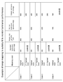
- FIG. 22 shows examples of three types of conversion curves (mapping curves) (a), (b), and (c). In this example, the maximum level after conversion is V_100 * N, and the intermediate conversion level is different.
- FIG. 23 schematically shows a mapping curve (mapping / curve) table corresponding to the three types of conversion curves (mapping curves) (a), (b), and (c) shown in FIG.
- FIG. 24 shows a configuration example of the transport stream TS.
- the transport stream TS includes a PES packet “PID1: video PES1” of the video elementary stream.
- PES packet “PID1: video PES1” of the video elementary stream.
- tone mapping SEI information and HDR / conversion SEI information are inserted.
- the transport stream TS includes a PMT (Program Map Table) as PSI (Program Specific Information).
- PSI Program Specific Information
- This PSI is information describing to which program each elementary stream included in the transport stream belongs.
- the transport stream TS includes an EIT (Event Information Table) as SI (Serviced Information) for managing events (programs).
- the PMT there is an elementary loop having information related to each elementary stream.
- a video elementary loop (Video ES loop).
- information such as a stream type and a packet identifier (PID) is arranged corresponding to the above one video elementary stream, and information related to the video elementary stream is described.
- a descriptor is also arranged.
- the HDR simple descriptor (HDR_simple descriptor) or the HDR full descriptor (HDR_full descriptor) is arranged under the video elementary loop (Video ES loop) of the PMT. As described above, these descriptors indicate that tone mapping SEI information or HDR / conversion SEI information is inserted in the video stream. Further, a level mapping curve descriptor (level_mapping_curve descriptor) is arranged under the video elementary loop (Video ES loop) of the PMT.
- FIG. 25 illustrates a configuration example of the receiving device 200.
- the receiving apparatus 200 includes a control unit 201, a receiving unit 202, a system decoder 203, a video decoder 204, an HDR processing unit 205, a color space conversion unit 206, and a display unit 207.
- the control unit 201 includes a CPU (Central Processing Unit), and controls the operation of each unit of the reception device 200 based on a control program stored in a predetermined storage.
- CPU Central Processing Unit
- the receiving unit 202 receives the transport stream TS transmitted from the transmitting device 100 on a broadcast wave.
- the system decoder 203 extracts a video stream (elementary stream) from the transport stream TS. Further, the system decoder 203 extracts the above-described HDR simple descriptor (HDR_simple descriptor) or HDR ⁇ full descriptor (HDR_full descriptor) from the transport stream TS, and transmits the extracted HDR simple descriptor (HDR_full descriptor) to the control unit 201.
- HDR simple descriptor HDR_simple descriptor
- HDR ⁇ full descriptor HDR_full descriptor
- the control unit 201 can recognize from the descriptor whether tone mapping SEI information or HDR / conversion SEI information is inserted in the video stream.
- the control unit 203 recognizes that there is such SEI information, for example, the video decoder 204 can be controlled to actively acquire the SEI information.
- the system decoder 203 extracts a level mapping curve descriptor (level_mapping_curve descriptor) from the transport stream TS and sends it to the control unit 201.
- the control unit 201 can control the conversion process using the conversion curve information in the HDR processing unit 205 based on a mapping curve (mapping / curve) table included in the descriptor.
- the video decoder 204 performs decoding processing on the video stream extracted by the system decoder 203 to obtain baseband video data (transmission video data).
- the video decoder 204 extracts the SEI message inserted in the video stream and sends it to the control unit 201.
- This SEI message includes a tone mapping information SEI message (Tone mapping information SEI message) and an HDR conversion SEI message (HDR conversion SEI message).
- the control unit 201 controls decoding processing and display processing based on the SEI information.
- the HDR processing unit 205 converts the high-level level range of the video data (transmission video data) obtained by the video decoder 204 so that the maximum level becomes a predetermined level based on the auxiliary information. In this case, as described above, the HDR processing unit 205 performs processing corresponding to the transmission video data (a), (b), and (c) (see FIGS. 6, 7, and 9). Details of the HDR processing unit 205 will be described later.
- the color space conversion unit 206 converts the video data obtained by the HDR processing unit 205 from the YUV color space to the RGB color space.
- the display unit 207 displays an image using the video data after color space conversion.
- FIG. 26 illustrates a configuration example of the HDR processing unit 205.
- the HDR processing unit 205 includes a clipping processing unit 251, a marking processing unit 252, and a range mapping processing unit 253.
- the transmission video data (a) (see FIG. 6)
- the transmission video data (decoded pixel data) is input to the clipping processing unit 251 and processing using the filter information is performed.
- transmission video data (b) when V_th (threshold_clipping_level) ⁇ V_100, both processing using filter information and processing using conversion curve information are possible.
- transmission video data (decoded pixel data) is input to the clipping processing unit 251.
- transmission video data (decoded pixel data) is input to the range mapping processing unit 253.
- transmission video data (decoded pixel data) is input to the range mapping processing unit 253, and processing using conversion curve information is performed.
- the clipping processing unit 251 uses the threshold clipping level (Threshold_clipping_level) from the pixel data constituting the transmission video data, and extracts pixel data of this level or higher as a target of remapping processing.
- the threshold clipping level (Threshold_clipping_level) is V_100.
- FIG. 27A shows a part of pixel data constituting transmission video data, and it is assumed that only pixel data shown in white is above the threshold clipping level.
- the clipping processing unit 251 pixel data to be subjected to remapping processing is extracted as shown in white in FIG. Note that pixel data that is not subject to remapping processing has the same value as the output of the HDR processing unit 205.
- the marking processing unit 252 performs the filtering operation of the filter type indicated by the operator type (Operator_type) for each pixel data subjected to the remapping processing, using the surrounding pixel data, and classifies the level.
- FIG. 27C shows a state in which each pixel data subject to remapping processing is divided into levels.
- FIG. 27D shows, for example, three stages, that is, (1) “highest level” and (2) “2nd”. highest level ”, (3)“ 3rd The state is divided into “highest level”.
- the level division stage is set to three stages for easy understanding, but actually, it is set more finely.
- the range mapping processing unit 253 maps the value of each pixel data to a value according to the level-divided stage, and outputs it.
- the range mapping processing unit 253 performs mapping by using a range maximum percentage (renge_max_percent), that is, a value of N and a monitor luminance dynamic range (Monitor Luminance dynamic range).
- renge_max_percent a range maximum percentage
- monitor luminance dynamic range Monitoring Luminance dynamic range
- FIG. 28 shows an example of range mapping. This example shows a case where the range maximum, the percentage (renge_max_percent) is “4”, and the monitor luminance dynamic range is 400%.
- the pixel data of “highest level” is mapped to a value at which the output luminance percentage, which is the output luminance of the display unit 207, is 400%.
- (2) "2nd The pixel data of the “highest level” is mapped to a value at which the output luminance percentage is 300%.
- (3) “3rd The pixel data of the “highest level” is mapped to a value with an output luminance percentage of 200%.
- FIG. 29 shows another example of range mapping.
- the marking processing unit 252 (1) “highest level” and (2) “2nd” in order to simplify the explanation. It is assumed that the level is divided into two levels of “highest level”.
- the example of “Case 1” indicates a case where the range max percent is “8” and the monitor luminance dynamic range is “800%”.
- the pixel data of “highest level” is mapped to a value with an output luminance percentage of 800%.
- (2) "2nd The pixel data of “highest level” is mapped to a value at which the output luminance percentage is 400%.
- the example of “Case 2” shows a case where the range max percent is “4” and the monitor luminance dynamic range is 800%.
- the pixel data of “highest level” is mapped to a value with an output luminance percentage of 400%.
- (2) "2nd The pixel data of the “highest level” is mapped to a value with an output luminance percentage of 200%.
- the dynamic range of the video data is up to 400%, even if the dynamic range of the monitor luminance is up to 800%, the maximum value of the output luminance percentage is 400% of the dynamic range of the video data. Selected to correspond. Thereby, it is suppressed that a high-intensity part becomes unnecessarily bright and unnatural.
- the example of “Case 3” shows a case where the range max percent is “8” and the monitor luminance dynamic range is 400%.
- the pixel data of “highest level” is mapped to a value with an output luminance percentage of 400%.
- (2) "2nd The pixel data of the “highest level” is mapped to a value with an output luminance percentage of 200%.
- the maximum value of the output luminance percentage is the dynamic range of the monitor luminance video data. Is selected to correspond to 400%. As a result, display video data matching the dynamic range of the monitor luminance can be obtained, and a so-called white-out state where the high luminance side is crushed can be avoided.
- the example of “Case 4” shows a case where the range max percent is “8” and the monitor luminance dynamic range is 100%.
- the pixel data of “highest level” is mapped to a value at which the output luminance percentage becomes 100%.
- (2) "2nd The pixel data of the “highest level” is mapped to a value with an output luminance percentage of less than 100%.
- the range mapping processing unit 253 maps the value of each pixel data in the conversion target level range from V_th to V_100 * N in the transmission video data with reference to the mapping curve table, and outputs the data.
- the conversion curve has a range max percentage (renge_max_percent), that is, the value of N and the maximum level after conversion determined using the monitor luminance dynamic range (Monitor Luminance dynamic range) Is used.
- the method for determining the maximum level after the conversion is performed in the same manner as in the case of using the filter information described above (see FIG. 29). For example, if the range max percentage is “8” and the monitor luminance dynamic range is “800%”, the maximum level is determined to be a value at which the output luminance percentage is 800%. For example, when the range max percentage is “4” and the monitor luminance dynamic range is 800%, the maximum level is determined to be a value at which the output luminance percentage is 400%.
- the value as it is is set as the output of the range mapping processing unit 253, and hence the output of the HDR processing unit 205.
- FIG. 30 shows an example of range mapping (Case IV 5). This example shows a case where the range max, the percentage (renge_max_percent) is “4”, and the monitor luminance dynamic range (Monitor Luminance dynamic range) is 200%. In this case, the maximum level is determined to be a value at which the output luminance percentage is 200%. In this example, “960”, which is the maximum level of transmission video data, is converted to level “480”.
- the range mapping processing unit 253 uses information on monitor luminance dynamic range (Monitor Luminance dynamic range).
- monitor luminance dynamic range can be determined based on information obtained from the EDID on the monitor side via HDMI. Further, “Range_max_percent” and each element of the SEI message and descriptor can be shared by the set-top box and the monitor by defining them in Vender Specific Info Frame.
- HDMI is a registered trademark.
- the reception unit 202 receives the transport stream TS transmitted from the transmission device 100 on a broadcast wave.
- This transport stream TS is supplied to the system decoder 203.
- the system decoder 203 extracts a video stream (elementary stream) from the transport stream TS.
- the system decoder 203 extracts an HDR simple descriptor (HDR_simpleordescriptor) or an HDR full descriptor (HDR_full descriptor) from the transport stream TS and sends the extracted HDR / simple descriptor (HDR_full descriptor) to the control unit 201.
- HDR simple descriptor HDR_simpleordescriptor
- HDR full descriptor HDR_full descriptor
- the control unit 201 recognizes whether or not tone mapping SEI information or HDR / conversion SEI information is inserted in the video stream by this descriptor.
- the control unit 203 recognizes that there is such SEI information, for example, the video decoder 204 is controlled to actively acquire the SEI information.
- the video stream extracted by the system decoder 204 is supplied to the video decoder 204.
- the video decoder 204 decodes the video stream to generate baseband video data. Further, the video decoder 204 extracts the SEI message inserted in this video stream and sends it to the control unit 201.
- This SEI message includes tone mapping information SEI message (Tone mapping information SEI message) and HDR conversion SEI message (HDR conversion SEI message).
- the control unit 201 controls the decoding process and the display process based on the SEI information.
- Video data (transmission video data) obtained by the video decoder 204 is supplied to the HDR processing unit 205.
- the level range on the high level side of the transmission video data is converted based on the auxiliary information so that the maximum level becomes a predetermined level.
- the video data obtained by the HDR processing unit 206 is converted from the YUV color space to the RGB color space by the color space conversion unit 206 and then supplied to the display unit 207.
- the display unit 207 displays an image based on the received video data in a luminance dynamic range corresponding to the luminance dynamic range of the transmitted video data and further the luminance dynamic range of the monitor.
- the transmission apparatus 100 receives transmission video data obtained by applying a gamma curve to input video data having a level range of 0% to 100% * N. It is transmitted together with auxiliary information for converting the high luminance level on the side. Therefore, for example, on the receiving side, it is possible to convert the high-luminance level of the transmission video data by this auxiliary information, and it is possible to display in the appropriate luminance dynamic range on the receiving side.
- identification information indicating that auxiliary information is inserted in the layer of the video stream is inserted in the layer of the transport stream TS transmitted from the transmission device 100 to the reception device 200. Is. Therefore, the receiving side can know that auxiliary information is inserted in the video stream without decoding the video stream, and can appropriately extract the auxiliary information from the video stream.
- FIG. 31 shows a configuration example of the stream distribution system 30.
- This stream distribution system 30 is an MPEG-DASH based stream distribution system.
- N IPTV clients 33-1, 33-2,..., 33-N are connected to a DASH segment streamer 31 and a DASH ⁇ ⁇ MPD server 32 via a CDN (Content32Delivery Network) 34.
- CDN Content32Delivery Network
- the DASH segment streamer 31 generates a DASH specification stream segment (hereinafter referred to as “DASH segment”) based on media data (video data, audio data, subtitle data, etc.) of predetermined content, and HTTP from the IPTV client. Send segments on demand.
- DASH segment streamer 31 may be a dedicated server for streaming, or may be used as a web server.
- the DASH segment streamer 31 responds to a request for a segment of a predetermined stream sent from the IPTV client 33 (33-1, 33-2,..., 33-N) via the CDN 14, and receives the stream. Are sent to the requesting IPTV client 33 via the CDN 34.
- the IPTV client 33 refers to the rate value described in the MPD (Media Presentation Description) file and selects the stream with the optimum rate according to the state of the network environment where the client is placed. Make a request.
- the DASH MPD server 32 is a server that generates an MPD file for acquiring a DASH segment generated in the DASH segment streamer 31.
- the MPD file is generated based on the content metadata from the content management server (not shown in FIG. 31) and the segment address (url) generated in the DASH segment streamer 31.
- each attribute is described using an element called “Representation” for each stream such as video and audio.
- representations are described by dividing the representation.
- the IPTV client 33 can select an optimum stream according to the state of the network environment in which the IPTV client 33 is placed, with reference to the rate value, as described above.
- FIG. 32 shows an example of the relationship between the structures arranged hierarchically in the MPD file described above.
- a media presentation Media Presentation
- a media presentation includes a plurality of periods (Periods) separated by time intervals. For example, the first period starts from 0 seconds, the next period starts from 100 seconds, and so on.
- the plurality of representations include a group of representations related to video data streams having the same content with different stream attributes, for example, rates, grouped by the above-described adaptation set (AdaptationSet).
- the representation includes segment info (SegmentInfo).
- SegmentInfo As shown in FIG. 32 (d), a plurality of media segments (Media) in which information for each initialization segment (Initialization Segment) and each segment (Segment) obtained by further dividing the period is described. Segment) exists. In the media segment, there is information on an address (url) for actually acquiring segment data such as video and audio.
- stream switching can be freely performed between a plurality of representations grouped in the adaptation set. This makes it possible to select an optimal rate stream according to the state of the network environment where the IPTV client is placed, and to enable continuous video distribution.
- FIG. 33 (a) shows the segment structure. There are three types of segments depending on the difference in constituent elements. The first is a structure having a plurality of “Media Segment” for storing fragmented video data in addition to the initialization information “Initialization Segment” of the codec. Second, there is only one “Media Segment”. The third is a structure using “Media Segment” integrated with codec initialization information “Initialization Segment”.
- FIGS. 33B and 33C show “examples of data formats of segments corresponding to ISOBMFF and MPEG-2TS when a structure having only one Media Segment is used.
- the tone mapping information SEI message (Tone mapping information SEI message) and HDR conversion SEI message (HDR conversion) are included in the "Media Segment” part.
- a video stream in which SEI (message) is inserted is arranged.
- FIG. 34 shows the information included in “Initialization Segment” and the information included in “Media Segment” in the segment data format corresponding to MPEG-2 TS (see FIG. 33C) in the transport stream. It shows schematically which information.
- the IPTV client 33 33-1, 33-2,..., 33-N
- the address url
- “Initialization Segment” and “Media Segment” are acquired and image display is performed.
- an SEI message having gamma curve information and additional information for remapping is inserted into the video stream layer, and the SEI message is inserted into the system layer (container layer).
- a descriptor having identification information on the presence or absence of the message is inserted. Therefore, the IPTV client 33 can perform the same processing as the reception device 200 in the transmission / reception system 10 shown in FIG.
- MMT MPEG Media Transport
- FIG. 35 shows a configuration example of a transmission / reception system 40 that handles an MMT structure transmission stream.
- the transmission / reception stem 40 includes a transport packet transmission device 300 and a transport packet reception device 400.
- the transmitting apparatus 300 generates a transport stream including an MMT structure (see ISO / IEC CD 23008-1), that is, an MMT packet, and transmits this transport stream through an RF transmission line or a communication network transmission line. Send to.
- a first MMT packet including video or audio transmission media in the payload and a second MMT packet including information related to the transmission medium in the payload are time-divisionally divided at least in the size of the fragmented packet. Are multiplexed.
- the receiving device 400 receives the above-described transmission stream from the transmission side through the RF transmission line or the communication network transmission line.
- the receiving apparatus 400 processes the transmission medium extracted from the transmission stream using the decoding time and the display time acquired based on the time information, displays an image, and outputs a sound.
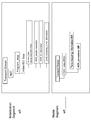
- FIG. 36 shows the structure of the MMT packet in a tree format.
- the MMT packet includes an MMT packet header (MMTMMPacket Header), an MMT payload header (MMT Payload Header), and an MMT payload (MMT Payload).
- MMT payload includes a message (Message), an MPU (Media Processing Unit), an FEC correction symbol (FEC Repair Symbol), and the like, and the signaling is performed by a payload type (payload_type) included in the MMT payload header.
- payload_type payload type
- the MPU may be fragmented and subdivided into MFU (MMTMMFragment Unit).
- MFU Header an MFU header
- the MMT payload includes an MPU related to media data such as video and audio, and an MPU related to metadata.
- the MMT packet including each MPU can be identified by a packet ID (Packet_ID) present in the MMT packet header.
- a tone mapping information SEI message (HoneSEmapping information SEI message) or HDR ⁇ conversion ⁇ SEI message (HDR conversion SEI message) is included in the MMT payload.
- the inserted video stream is arranged.
- an HDR description table including the same contents as the above-described HDR simple descriptor (HDR_simple descriptor) or HDR full descriptor (HDR_full descriptor), and level mapping curve descriptor (level_mapping_curve descriptor) A message with (HDR description table) is defined.
- FIG. 37 shows a structure example (Syntax) of an HDR description message (HDR description message) having an HDR simple description table.
- a 16-bit field of “message_id” indicates an HDR description message.
- the 8-bit field of “version” indicates the version of this message.
- a 16-bit field of “lengh” indicates the length (size) of this message, and indicates the number of subsequent bytes.
- This HDR description message includes an HDR simple description table (HDR simple description table).
- FIG. 38 shows a structural example (Syntax) of the HDR simple description table.
- An 8-bit field of “table_id” indicates an HDR simple description table.
- the 8-bit field of “version” indicates the version of this table.
- “Table_id” and “version” are uniquely assigned in the system.
- the 16-bit field of “length” indicates the overall (size) of this table.
- the 16-bit field of “packet_id” is the same as “packet_id” included in the MMT packet header. Thereby, the association at the asset level is performed.
- tone mapping SEI information (gamma curve information) is present in the video layer (video stream layer) as in the HDR simple descriptor (HDR_simple descriptor) of FIG. Flag information indicating whether or not. “1” indicates that tone mapping SEI information exists, and “0” indicates that tone mapping SEI information does not exist.
- HDR / conversion SEI information (additional information) exists in the video layer (video stream layer) as in the HDR simple descriptor (HDR_simple descriptor) of FIG. Flag information indicating whether or not. “1” indicates that HDR / conversion SEI information exists, and “0” indicates that HDR / conversion SEI information does not exist.
- FIG. 39 shows another structural example (Syntax) of an HDR description message (HDR description message) having an HDR description table.
- a 16-bit field of “message_id” indicates an HDR description message.
- the 8-bit field of “version” indicates the version of this message.
- a 16-bit field of “length” indicates the length (size) of this message, and indicates the number of subsequent bytes.
- This HDR description message includes an HDR full description table (HDR full description table).
- FIG. 40 shows a structural example (Syntax) of the HDR full description table.
- An 8-bit field of “table_id” indicates an HDR simple description table.
- the 8-bit field of “version” indicates the version of this table.
- “Table_id” and “version” are uniquely assigned in the system.
- the 16-bit field of “length” indicates the overall (size) of this table.
- the 16-bit field of “packet_id” is the same as “packet_id” included in the MMT packet header. Thereby, the association at the asset level is performed.
- this HDR full description table includes the same information as in the HDR full descriptor (HDR_full descriptor) of FIG. 20 including “tone_mapping_SEI_existed” and “HDR_conversion_SEI_existed”. ing.
- FIG. 41 is a diagram showing a structure example of an HDR description message having a level mapping curve table.
- a 16-bit field of “message_id” indicates an HDR description message.
- the 8-bit field of “version” indicates the version of this message.
- a 16-bit field of “length” indicates the length (size) of this message, and indicates the number of subsequent bytes.
- This HDR description message includes a level mapping curve table (Level_mapping_curve_table).
- FIG. 42 shows a structural example (Syntax) of the level mapping curve table.
- the 8-bit field of “table_id” indicates a level mapping curve table.
- the 8-bit field of “version” indicates the version of this table. “Table_id” and “version” are uniquely assigned in the system.
- the 16-bit field of “length” indicates the overall (size) of this table.
- the 16-bit field of “packet_id” is the same as “packet_id” included in the MMT packet header. Thereby, the association at the asset level is performed.
- mapping_curve_table_id “number of levels N”, “number of curve types C” and “curve_data” are the same as the level mapping curve descriptor (level_mapping_curve descriptor) in FIG. Contains information.
- the IPTV client 33 (33-1, 33-2,..., 33-N) has an address (url) existing in the MPD file. Based on the information, “Initialization Segment” and “Media Segment” are acquired and image display is performed. At that time, processing using the SEI message can be performed in the same manner as the receiving apparatus 200 in the transmission / reception system 10 shown in FIG.
- an SEI message having gamma curve information and additional information for remapping is inserted into the video stream layer, and the SEI message is inserted into the system layer (container layer).
- a description table having presence / absence identification information is inserted. Therefore, the transport packet receiving apparatus 400 can perform the same processing as the receiving apparatus 200 in the transmission / reception system 10 shown in FIG.
- this technique can also take the following structures.
- a transmission device comprising: a transmission unit configured to transmit the transmission video data together with auxiliary information for converting a high-luminance level on the reception side.
- the transmission unit transmits a container of a predetermined format including a video stream obtained by encoding the transmission video data,
- the transmission apparatus according to (1) further including an auxiliary information insertion unit that inserts the auxiliary information into the layer of the video stream and / or the layer of the container.
- the transmission apparatus further including: an identification information insertion unit that inserts identification information indicating that the auxiliary information is inserted into the video stream layer into the container layer.
- the processing unit For the output video data obtained by applying the gamma curve to the input video data, a level corresponding to a level of 100% to 100% * N of the input video data is further set to 100% of the input video data.
- the transmission apparatus according to any one of (1) to (3), wherein the transmission video data is obtained by performing processing for conversion to a level corresponding to.
- the auxiliary information includes information on a filter applied to pixel data at a level corresponding to 100% of the input video data of the transmission video data.
- the processing unit The output video data obtained by applying the gamma curve to the input video data further corresponds to 100% * N of the input video data from a threshold value equal to or lower than the level corresponding to 100% of the input video data.
- the transmission video data is obtained by performing a process of converting the level up to a level between the threshold value and a level corresponding to 100% of the input video data. Any one of (1) to (3) Transmitter device.
- the auxiliary information includes information on a filter applied to pixel data from the threshold value of the transmission video data to a level corresponding to 100% of the input video data.
- auxiliary information includes information on a conversion curve applied to pixel data from the threshold value of the transmission video data to a level corresponding to 100% of the input video data.
- the processing unit The transmission apparatus according to any one of (1) to (3), wherein output video data obtained by applying the gamma curve to the input video data is used as the transmission video data as it is.
- the auxiliary information includes information on a conversion curve applied to a high level side of the transmission video data.
- a receiving unit that receives transmission video data obtained by applying a gamma curve to input video data having a level range of 0% to 100% * N (N is a number greater than 1);
- a receiving apparatus comprising: a processing unit that converts a level range on the high level side of the transmission video data based on auxiliary information received together with the transmission video data so that the maximum level becomes a predetermined level.
- the processing unit The receiving apparatus according to (12), wherein the predetermined level is determined based on the N information included in the auxiliary information and information on a luminance dynamic range of the monitor.
- the transmission video data has a level corresponding to a level of 100% to 100% * N of the input video data with respect to the output video data obtained by applying the gamma curve to the input video data.
- the processing unit Applying a filter specified by the filter information included in the auxiliary information to the level of each pixel data corresponding to 100% of the input video data of the transmission video data, 100% of the input video data
- the receiving device according to (12) or (13), wherein the receiving device converts the level to a level between the level corresponding to 1 and the predetermined level.
- the transmission video data is further compared with the output video data obtained by applying the gamma curve to the input video data from a threshold value equal to or lower than a level corresponding to 100% of the input video data.
- Video data obtained by performing processing for converting a level corresponding to 100% * N of data to a level between the threshold and a level corresponding to 100% of the input video data The processing unit Applying a filter specified by filter information included in the auxiliary information to each pixel data from the threshold value to a level corresponding to 100% of the input video data of the transmission video data, The receiving device according to (12) or (13), wherein the receiving device converts the level to a level up to a level. (16)
- the transmission video data is further compared with the output video data obtained by applying the gamma curve to the input video data from a threshold value equal to or lower than a level corresponding to 100% of the input video data.
- Video data obtained by performing processing for converting a level corresponding to 100% * N of data to a level between the threshold and a level corresponding to 100% of the input video data The processing unit Applying the conversion curve information included in the auxiliary information to each pixel data of the transmission video data from the threshold value to a level corresponding to 100% of the input video data, between the threshold value and the predetermined level.
- the receiving device according to (12) or (13).
- the transmission video data is the video data as is of the output video data obtained by applying the gamma curve to the input video data
- the processing unit Conversion curve information included in the auxiliary information includes each pixel data of the transmission video data from a threshold value equal to or lower than a level corresponding to 100% of the input video data to a level corresponding to 100% * N of the input video data. Is applied to convert the level from the threshold value to a level between the predetermined level corresponding to L% * 100 (L is a number equal to or less than N) of the input video data. (12) or (13) Receiver device.
- auxiliary information filter information, conversion curve information
- filter information for converting the transmission video data obtained by applying a gamma curve to HDR input video data to a high luminance level on the receiving side.
- DESCRIPTION OF SYMBOLS 10 ... Transmission / reception system 30 ... Stream delivery system 31 ... DASH segment streamer 32 ... DASH MPD server 33-1 to 33-N ... IPTV client 34 ... CDN DESCRIPTION OF SYMBOLS 40 ... Transmission / reception system 100 ... Transmission apparatus 101 ... Control part 102 ... Camera 103 ... Color space conversion part 104 ... Gamma processing part 105 ... Video encoder 106 ... System encoder DESCRIPTION OF SYMBOLS 107 ... Transmission part 200 ... Reception apparatus 201 ... Control part 202 ... Reception part 203 ... System decoder 204 ... Video decoder 205 ... HDR processing part 206 ... Color space conversion 207: Display unit 251: Clipping processing unit 252 ... Marking processing unit 253 ... Range mapping processing unit 300 ... Transport packet transmitting device 400 ... Transport packet receiving device
Landscapes
- Engineering & Computer Science (AREA)
- Multimedia (AREA)
- Signal Processing (AREA)
- Picture Signal Circuits (AREA)
- Two-Way Televisions, Distribution Of Moving Picture Or The Like (AREA)
- Compression Or Coding Systems Of Tv Signals (AREA)
- Studio Devices (AREA)
Abstract
Description
0%から100%*N(Nは1より大きい数)のレベル範囲を持つ入力ビデオデータにガンマカーブを適用して伝送ビデオデータを得る処理部と、
上記伝送ビデオデータを、受信側で高輝度のレベルを変換するための補助情報と共に送信する送信部とを備える
送信装置にある。
0%から100%*N(Nは1より大きい数)のレベル範囲を持つ入力ビデオデータにガンマカーブを適用して得られた伝送ビデオデータを受信する受信部と、
上記伝送ビデオデータの高レベル側のレベル範囲を、該伝送ビデオデータと共に受信される補助情報に基づいて、最大レベルが所定レベルとなるように変換する処理部とを備える
受信装置にある。
1.実施の形態
2.変形例
[送受信システムの構成例]
図1は、実施の形態としての送受信システム10の構成例を示している。この送受信システム10は、送信装置100および受信装置200により構成されている。
図2を参照して、伝送ビデオデータ(a)について説明する。「Content data level range」は、入力ビデオデータの0%から100%*Nまでのレベル範囲を示す。「V_100*N」は、入力ビデオデータの100%*Nのレベルに相当する、ガンマカーブ適用後のビデオデータ(出力ビデオデータ)のレベルを示す。「V_100」は、入力ビデオデータの100%のレベルに相当する、ガンマカーブ適用後のビデオデータ(出力ビデオデータ)のレベルを示す。「Encoder Input Pixel data range」は、伝送ビデオデータの0からV_100までのレベル範囲を示す。例えば、0~V_100の階調数は、所定ビット、例えば8ビットで表される。
図3を参照して、伝送ビデオデータ(b)について説明する。「Content data level range」、「V_100*N」、「Encoder Input Pixel data range」は、図2と同じである。「V_th」は、入力ビデオデータの100%のレベルに相当するレベル以下の閾値であるスレッショルド・クリッピング・レベル(Threshold_clipping_level)を示す。
図4を参照して、伝送ビデオデータ(c)について説明する。「Content data level range」、「V_100*N」は、図2と同じである。「Encoder Input Pixel data range」は、伝送ビデオデータの0からV_100*Nのレベル範囲を示す。伝送ビデオデータ(c)は、入力ビデオデータにガンマカーブ(実線a参照)を適用して得られた出力ビデオデータそのままである。この伝送ビデオデータ(c)は、入力ビデオデータの0%から100%*Nのレベルに相当するレベルを持ち、高ダイナミックレンジのビデオデータの体裁をとる。
図6を参照して、伝送ビデオデータ(a)に対する変換処理について説明する。「Decoded pixel data range」は、入力ビデオデータ(伝送ビデオデータ)の0からV_100までのレベル範囲を示す。「Display Level range」は、モニタ(ディスプレイ)の0%の輝度から100%*Nの輝度までのレベル範囲を示す。そして、実線aは、モニタのガンマ特性を示すカーブであり、上述したガンマカーブ(図2の実線a参照)とは逆の特性となる。
図7を参照して、伝送ビデオデータ(b)に対する変換処理について説明する。「Decoded pixel data range」は、入力ビデオデータ(伝送ビデオデータ)の0からV_100までのレベル範囲を示す。「Display Level range」は、モニタ(ディスプレイ)の0%の輝度から100%*Nの輝度までのレベル範囲を示す。そして、実線aは、モニタのガンマ特性を示すカーブであり、上述したガンマカーブ(図3の実線a参照)とは逆の特性となる。
図9を参照して、伝送ビデオデータ(b)に対する変換処理について説明する。「Decoded pixel data range」は、入力ビデオデータ(伝送ビデオデータ)の0からV_100*Nまでのレベル範囲を示す。「Display Level range」は、モニタ(ディスプレイ)の0%の輝度から100%*Lの輝度までのレベル範囲を示す。そして、実線aは、モニタのガンマ特性を示すカーブであり、上述したガンマカーブ(図4の実線a参照)とは逆の特性となる。
図10は、送信装置100の構成例を示している。この送信装置100は、制御部101と、カメラ102と、色空間変換部103と、ガンマ処理部104と、ビデオエンコーダ105と、システムエンコーダ106と、送信部107を有している。制御部101は、CPU(Central Processing Unit)を備えて構成され、所定のストレージに格納されている制御プログラムに基づいて、送信装置100の各部の動作を制御する。
上述したように、ビデオストリームのレイヤに、ガンマカーブ情報や補助情報が挿入される。例えば、符号化方式がMPEG4-AVCである場合、または、HEVCのような、NALパケットなどの符号化構造が似通っている符号化方式である場合、この補助情報は、アクセスユニット(AU)の“SEIs”の部分に、SEIメッセージとして挿入される。
図25は、受信装置200の構成例を示している。この受信装置200は、制御部201と、受信部202と、システムデコーダ203と、ビデオデコーダ204と、HDR処理部205と、色空間変換部206と、表示部207を有している。制御部201は、CPU(Central Processing Unit)を備えて構成され、所定のストレージに格納されている制御プログラムに基づいて、受信装置200の各部の動作を制御する。
このHDR処理部205の詳細については、後述する。
図26は、HDR処理部205の構成例を示している。HDR処理部205は、クリッピング処理部251と、マーキング処理部252と、レンジマッピング処理部253とを有している。伝送ビデオデータ(a)の場合(図6参照)、伝送ビデオデータ(decoded pixel data)はクリッピング処理部251に入力され、フィルタ情報を用いた処理が行われる。
[MPEG-DASHベースのストリーム配信システムへの適用]
なお、上述実施の形態においては、コンテナがトランスポートストリーム(MPEG-2 TS)である例を示した。しかし、本技術は、インターネット等のネットワークを利用して受信端末に配信される構成のシステムにも同様に適用できる。インターネットの配信では、MP4やそれ以外のフォーマットのコンテナで配信されることが多い。
近年、次世代放送向けのトランスポート構造としてMMT(MPEG Media Transport)構造が脚光を浴びつつある。このMMT構造は、IPネットワークとの共存が主な特徴である。このMMT構造伝送ストリームを扱う送受信システムに本技術を適用することも考えられる。
(1)0%から100%*N(Nは1より大きい数)のレベル範囲を持つ入力ビデオデータにガンマカーブを適用して伝送ビデオデータを得る処理部と、
上記伝送ビデオデータを、受信側で高輝度のレベルを変換するための補助情報と共に送信する送信部とを備える
送信装置。
(2)上記送信部は、上記伝送ビデオデータが符号化されて得られたビデオストリームを含む所定フォーマットのコンテナを送信し、
上記ビデオストリームのレイヤおよび/または上記コンテナのレイヤに上記補助情報を挿入する補助情報挿入部を備える
前記(1)に記載の送信装置。
(3)上記ビデオストリームのレイヤに上記補助情報の挿入があることを示す識別情報を上記コンテナのレイヤに挿入する識別情報挿入部を備える
前記(2)に記載の送信装置。
(4)上記処理部は、
上記入力ビデオデータに上記ガンマカーブを適用して得られた出力ビデオデータに対し、さらに、上記入力ビデオデータの100%から100%*Nのレベルに相当するレベルを、上記入力ビデオデータの100%に相当するレベルに変換する処理を行って上記伝送ビデオデータを得る
前記(1)から(3)のいずれかに記載の送信装置。
(5)上記補助情報は、上記伝送ビデオデータの上記入力ビデオデータの100%に相当するレベルの画素データに適用するフィルタの情報を含む
前記(4)に記載の送信装置。
(6)上記処理部は、
上記入力ビデオデータに上記ガンマカーブを適用して得られた出力ビデオデータに対し、さらに、上記入力ビデオデータの100%に相当するレベル以下の閾値から上記入力ビデオデータの100%*Nに相当するレベルまでを、上記閾値から上記入力ビデオデータの100%に相当するレベルまでの間のレベルに変換する処理を行って上記伝送ビデオデータを得る
前記(1)から(3)のいずれかに記載の送信装置。
(7)上記補助情報は、上記伝送ビデオデータの上記閾値から上記入力ビデオデータの100%に相当するレベルまでの画素データに適用するフィルタの情報を含む
前記(6)に記載の送信装置。
(8)上記補助情報は、上記伝送ビデオデータの上記閾値から上記入力ビデオデータの100%に相当するレベルまでの画素データに適用する変換カーブの情報を含む
前記(6)に記載の送信装置。
(9)上記処理部は、
上記入力ビデオデータに上記ガンマカーブを適用して得られた出力ビデオデータをそのまま上記伝送ビデオデータにする
前記(1)から(3)のいずれかに記載の送信装置。
(10)上記補助情報は、上記伝送ビデオデータの高レベル側に適用する変換カーブの情報を含む
前記(9)に記載の送信装置。
(11)0%から100%*N(Nは1より大きい数)のレベル範囲を持つ入力ビデオデータにガンマカーブを適用して伝送ビデオデータを得る処理ステップと、
上記伝送ビデオデータを、受信側で高輝度のレベルを変換するための補助情報と共に送信する送信ステップとを備える
送信方法。
(12)0%から100%*N(Nは1より大きい数)のレベル範囲を持つ入力ビデオデータにガンマカーブを適用して得られた伝送ビデオデータを受信する受信部と、
上記伝送ビデオデータの高レベル側のレベル範囲を、該伝送ビデオデータと共に受信される補助情報に基づいて、最大レベルが所定レベルとなるように変換する処理部とを備える
受信装置。
(13)上記処理部は、
上記所定レベルを、上記補助情報に含まれる上記Nの情報およびモニタの輝度ダイナミックレンジの情報に基づいて決定する
前記(12)に記載の受信装置。
(14)上記伝送ビデオデータは、上記入力ビデオデータに上記ガンマカーブを適用して得られた出力ビデオデータに対し、さらに、上記入力ビデオデータの100%から100%*Nのレベルに相当するレベルを、上記入力ビデオデータの100%に相当するレベルに変換する処理を行って得られたビデオデータであり、
上記処理部は、
上記伝送ビデオデータの、上記入力ビデオデータの100%に相当するレベルの各画素データのレベルを、上記補助情報に含まれるフィルタ情報で特定されるフィルタを適用して、上記入力ビデオデータの100%に相当するレベルから上記所定のレベルまでの間のレベルに変換する
前記(12)または(13)に記載の受信装置。
(15)上記伝送ビデオデータは、上記入力ビデオデータに上記ガンマカーブを適用して得られた出力ビデオデータに対し、さらに、上記入力ビデオデータの100%に相当するレベル以下の閾値から上記入力ビデオデータの100%*Nに相当するレベルまでを、上記閾値から上記入力ビデオデータの100%に相当するレベルまでの間のレベルに変換する処理を行って得られたビデオデータであり、
上記処理部は、
上記伝送ビデオデータの、上記閾値から上記入力ビデオデータの100%に相当するレベルまでの各画素データを、上記補助情報に含まれるフィルタ情報で特定されるフィルタを適用して、上記閾値から上記所定レベルまでの間のレベルに変換する
前記(12)または(13)に記載の受信装置。
(16)上記伝送ビデオデータは、上記入力ビデオデータに上記ガンマカーブを適用して得られた出力ビデオデータに対し、さらに、上記入力ビデオデータの100%に相当するレベル以下の閾値から上記入力ビデオデータの100%*Nに相当するレベルまでを、上記閾値から上記入力ビデオデータの100%に相当するレベルまでの間のレベルに変換する処理を行って得られたビデオデータであり、
上記処理部は、
上記伝送ビデオデータの、上記閾値から上記入力ビデオデータの100%に相当するレベルまでの各画素データを、上記補助情報に含まれる変換カーブ情報を適用して、上記閾値から上記所定レベルまでの間のレベルに変換する
前記(12)または(13)に記載の受信装置。
(17)上記伝送ビデオデータは、上記入力ビデオデータに上記ガンマカーブを適用して得られた出力ビデオデータそのままのビデオデータであり、
上記処理部は、
上記伝送ビデオデータの、上記入力ビデオデータの100%に相当するレベル以下の閾値から上記入力ビデオデータの100%*Nに相当するレベルまでの各画素データを、上記補助情報に含まれる変換カーブ情報を適用して、上記閾値から上記入力ビデオデータのL%*100(LはN以下の数)に相当する上記所定レベルまでの間のレベルに変換する
前記(12)または(13)に記載の受信装置。
(18)0%から100%*N(Nは1より大きい数)のレベル範囲を持つ入力ビデオデータにガンマカーブを適用して得られた伝送ビデオデータを受信する受信ステップと、
上記伝送ビデオデータの高レベル側のレベル範囲を、該伝送ビデオデータと共に受信される補助情報に基づいて、最大レベルが所定レベルとなるように変換する処理ステップとを備える
受信方法。
30・・・ストリーム配信システム
31・・・DASHセグメントストリーマ
32・・・DASH MPDサーバ
33-1~33-N・・・IPTVクライアント
34・・・CDN
40・・・送受信システム
100・・・送信装置
101・・・制御部
102・・・カメラ
103・・・色空間変換部
104・・・ガンマ処理部
105・・・ビデオエンコーダ
106・・・システムエンコーダ
107・・・送信部
200・・・受信装置
201・・・制御部
202・・・受信部
203・・・システムデコーダ
204・・・ビデオデコーダ
205・・・HDR処理部
206・・・色空間変換部
207・・・表示部
251・・・クリッピング処理部
252・・・マーキング処理部
253・・・レンジマッピング処理部
300・・・トランスポートパケット送信装置
400・・・トランスポートパケット受信装置
Claims (18)
- 0%から100%*N(Nは1より大きい数)のレベル範囲を持つ入力ビデオデータにガンマカーブを適用して伝送ビデオデータを得る処理部と、
上記伝送ビデオデータを、受信側で高輝度のレベルを変換するための補助情報と共に送信する送信部とを備える
送信装置。 - 上記送信部は、上記伝送ビデオデータが符号化されて得られたビデオストリームを含む所定フォーマットのコンテナを送信し、
上記ビデオストリームのレイヤおよび/または上記コンテナのレイヤに上記補助情報を挿入する補助情報挿入部を備える
請求項1に記載の送信装置。 - 上記ビデオストリームのレイヤに上記補助情報の挿入があることを示す識別情報を上記コンテナのレイヤに挿入する識別情報挿入部を備える
請求項2に記載の送信装置。 - 上記処理部は、
上記入力ビデオデータに上記ガンマカーブを適用して得られた出力ビデオデータに対し、さらに、上記入力ビデオデータの100%から100%*Nのレベルに相当するレベルを、上記入力ビデオデータの100%に相当するレベルに変換する処理を行って上記伝送ビデオデータを得る
請求項1に記載の送信装置。 - 上記補助情報は、上記伝送ビデオデータの上記入力ビデオデータの100%に相当するレベルの画素データに適用するフィルタの情報を含む
請求項4に記載の送信装置。 - 上記処理部は、
上記入力ビデオデータに上記ガンマカーブを適用して得られた出力ビデオデータに対し、さらに、上記入力ビデオデータの100%に相当するレベル以下の閾値から上記入力ビデオデータの100%*Nに相当するレベルまでを、上記閾値から上記入力ビデオデータの100%に相当するレベルまでの間のレベルに変換する処理を行って上記伝送ビデオデータを得る
請求項1に記載の送信装置。 - 上記補助情報は、上記伝送ビデオデータの上記閾値から上記入力ビデオデータの100%に相当するレベルまでの画素データに適用するフィルタの情報を含む
請求項6に記載の送信装置。 - 上記補助情報は、上記伝送ビデオデータの上記閾値から上記入力ビデオデータの100%に相当するレベルまでの画素データに適用する変換カーブの情報を含む
請求項6に記載の送信装置。 - 上記処理部は、
上記入力ビデオデータに上記ガンマカーブを適用して得られた出力ビデオデータをそのまま上記伝送ビデオデータにする
請求項1に記載の送信装置。 - 上記補助情報は、上記伝送ビデオデータの高レベル側に適用する変換カーブの情報を含む
請求項9に記載の送信装置。 - 0%から100%*N(Nは1より大きい数)のレベル範囲を持つ入力ビデオデータにガンマカーブを適用して伝送ビデオデータを得る処理ステップと、
上記伝送ビデオデータを、受信側で高輝度のレベルを変換するための補助情報と共に送信する送信ステップとを備える
送信方法。 - 0%から100%*N(Nは1より大きい数)のレベル範囲を持つ入力ビデオデータにガンマカーブを適用して得られた伝送ビデオデータを受信する受信部と、
上記伝送ビデオデータの高レベル側のレベル範囲を、該伝送ビデオデータと共に受信される補助情報に基づいて、最大レベルが所定レベルとなるように変換する処理部とを備える
受信装置。 - 上記処理部は、
上記所定レベルを、上記補助情報に含まれる上記Nの情報およびモニタの輝度ダイナミックレンジの情報に基づいて決定する
請求項12に記載の受信装置。 - 上記伝送ビデオデータは、上記入力ビデオデータに上記ガンマカーブを適用して得られた出力ビデオデータに対し、さらに、上記入力ビデオデータの100%から100%*Nのレベルに相当するレベルを、上記入力ビデオデータの100%に相当するレベルに変換する処理を行って得られたビデオデータであり、
上記処理部は、
上記伝送ビデオデータの、上記入力ビデオデータの100%に相当するレベルの各画素データのレベルを、上記補助情報に含まれるフィルタ情報で特定されるフィルタを適用して、上記入力ビデオデータの100%に相当するレベルから上記所定のレベルまでの間のレベルに変換する
請求項12に記載の受信装置。 - 上記伝送ビデオデータは、上記入力ビデオデータに上記ガンマカーブを適用して得られた出力ビデオデータに対し、さらに、上記入力ビデオデータの100%に相当するレベル以下の閾値から上記入力ビデオデータの100%*Nに相当するレベルまでを、上記閾値から上記入力ビデオデータの100%に相当するレベルまでの間のレベルに変換する処理を行って得られたビデオデータであり、
上記処理部は、
上記伝送ビデオデータの、上記閾値から上記入力ビデオデータの100%に相当するレベルまでの各画素データを、上記補助情報に含まれるフィルタ情報で特定されるフィルタを適用して、上記閾値から上記所定レベルまでの間のレベルに変換する
請求項12に記載の受信装置。 - 上記伝送ビデオデータは、上記入力ビデオデータに上記ガンマカーブを適用して得られた出力ビデオデータに対し、さらに、上記入力ビデオデータの100%に相当するレベル以下の閾値から上記入力ビデオデータの100%*Nに相当するレベルまでを、上記閾値から上記入力ビデオデータの100%に相当するレベルまでの間のレベルに変換する処理を行って得られたビデオデータであり、
上記処理部は、
上記伝送ビデオデータの、上記閾値から上記入力ビデオデータの100%に相当するレベルまでの各画素データを、上記補助情報に含まれる変換カーブ情報を適用して、上記閾値から上記所定レベルまでの間のレベルに変換する
請求項12に記載の受信装置。 - 上記伝送ビデオデータは、上記入力ビデオデータに上記ガンマカーブを適用して得られた出力ビデオデータそのままのビデオデータであり、
上記処理部は、
上記伝送ビデオデータの、上記入力ビデオデータの100%に相当するレベル以下の閾値から上記入力ビデオデータの100%*Nに相当するレベルまでの各画素データを、上記補助情報に含まれる変換カーブ情報を適用して、上記閾値から上記入力ビデオデータのL%*100(LはN以下の数)に相当する上記所定レベルまでの間のレベルに変換する
請求項12に記載の受信装置。 - 0%から100%*N(Nは1より大きい数)のレベル範囲を持つ入力ビデオデータにガンマカーブを適用して得られた伝送ビデオデータを受信する受信ステップと、
上記伝送ビデオデータの高レベル側のレベル範囲を、該伝送ビデオデータと共に受信される補助情報に基づいて、最大レベルが所定レベルとなるように変換する処理ステップとを備える
受信方法。
Priority Applications (13)
| Application Number | Priority Date | Filing Date | Title |
|---|---|---|---|
| CN201480023446.4A CN105165001B (zh) | 2013-04-30 | 2014-04-16 | 发送设备、发送方法、接收设备、以及接收方法 |
| JP2015514806A JP6510404B2 (ja) | 2013-04-30 | 2014-04-16 | 送信装置、送信方法、受信装置および受信方法 |
| EP14791888.2A EP2993886A4 (en) | 2013-04-30 | 2014-04-16 | SENDING DEVICE, TRANSMISSION PROCEDURE, RECEPTION DEVICE AND RECEPTION PROCEDURE |
| BR112015026979-6A BR112015026979B1 (pt) | 2013-04-30 | 2014-04-16 | Dispositivos e métodos de transmissão e recepção |
| CN201910696258.2A CN110418166B (zh) | 2013-04-30 | 2014-04-16 | 发送接收方法、设备及系统 |
| EP21169413.8A EP3926963A3 (en) | 2013-04-30 | 2014-04-16 | Transmitting device, transmitting method, receiving device, and receiving method |
| RU2015145812A RU2657473C2 (ru) | 2013-04-30 | 2014-04-16 | Устройство передачи, способ передачи, устройство приема и способ приема |
| KR1020157030252A KR102241672B1 (ko) | 2013-04-30 | 2014-04-16 | 송신 장치, 송신 방법, 수신 장치 및 수신 방법 |
| US14/784,353 US9860505B2 (en) | 2013-04-30 | 2014-04-16 | Transmitting device, transmitting method, receiving device, and receiving method |
| US15/829,388 US10560674B2 (en) | 2013-04-30 | 2017-12-01 | Transmitting device, transmitting method, receiving device, and receiving method |
| US16/736,218 US11575866B2 (en) | 2013-04-30 | 2020-01-07 | Transmitting device, transmitting method, receiving device, and receiving method |
| US18/077,550 US12425656B2 (en) | 2013-04-30 | 2022-12-08 | Transmitting device, transmitting method, receiving device, and receiving method |
| US19/309,709 US20260059069A1 (en) | 2013-04-30 | 2025-08-26 | Transmitting device, transmitting method, receiving device, and receiving method |
Applications Claiming Priority (2)
| Application Number | Priority Date | Filing Date | Title |
|---|---|---|---|
| JP2013-096056 | 2013-04-30 | ||
| JP2013096056 | 2013-04-30 |
Related Child Applications (2)
| Application Number | Title | Priority Date | Filing Date |
|---|---|---|---|
| US14/784,353 A-371-Of-International US9860505B2 (en) | 2013-04-30 | 2014-04-16 | Transmitting device, transmitting method, receiving device, and receiving method |
| US15/829,388 Continuation US10560674B2 (en) | 2013-04-30 | 2017-12-01 | Transmitting device, transmitting method, receiving device, and receiving method |
Publications (1)
| Publication Number | Publication Date |
|---|---|
| WO2014178286A1 true WO2014178286A1 (ja) | 2014-11-06 |
Family
ID=51843420
Family Applications (1)
| Application Number | Title | Priority Date | Filing Date |
|---|---|---|---|
| PCT/JP2014/060877 Ceased WO2014178286A1 (ja) | 2013-04-30 | 2014-04-16 | 送信装置、送信方法、受信装置および受信方法 |
Country Status (8)
| Country | Link |
|---|---|
| US (5) | US9860505B2 (ja) |
| EP (2) | EP3926963A3 (ja) |
| JP (3) | JP6510404B2 (ja) |
| KR (1) | KR102241672B1 (ja) |
| CN (2) | CN110418166B (ja) |
| BR (1) | BR112015026979B1 (ja) |
| RU (1) | RU2657473C2 (ja) |
| WO (1) | WO2014178286A1 (ja) |
Cited By (48)
| Publication number | Priority date | Publication date | Assignee | Title |
|---|---|---|---|---|
| WO2015190246A1 (ja) * | 2014-06-13 | 2015-12-17 | ソニー株式会社 | 送信装置、送信方法、受信装置および受信方法 |
| WO2016072347A1 (ja) * | 2014-11-07 | 2016-05-12 | ソニー株式会社 | 送信装置、送信方法、受信装置および受信方法 |
| WO2016080233A1 (ja) * | 2014-11-17 | 2016-05-26 | ソニー株式会社 | 送信装置、ハイダイナミックレンジ画像データ送信方法、受信装置、ハイダイナミックレンジ画像データ受信方法およびプログラム |
| WO2016088344A1 (ja) * | 2014-12-03 | 2016-06-09 | パナソニックIpマネジメント株式会社 | データ生成方法、データ再生方法、データ生成装置及びデータ再生装置 |
| JP2016111692A (ja) * | 2014-12-03 | 2016-06-20 | パナソニックIpマネジメント株式会社 | データ生成方法、データ再生方法、データ生成装置及びデータ再生装置 |
| WO2016108268A1 (ja) * | 2014-12-29 | 2016-07-07 | ソニー株式会社 | 送信装置、送信方法、受信装置および受信方法 |
| JP2016122985A (ja) * | 2014-12-25 | 2016-07-07 | 株式会社東芝 | 画像処理システム、画像処理装置および画像処理方法 |
| WO2016132836A1 (ja) * | 2015-02-16 | 2016-08-25 | ソニー株式会社 | 情報処理装置、情報記録媒体、および情報処理方法、並びにプログラム |
| WO2016147625A1 (en) * | 2015-03-17 | 2016-09-22 | Canon Kabushiki Kaisha | Signal processing apparatus, signal processing method, and image capturing apparatus |
| JP2016195450A (ja) * | 2015-03-24 | 2016-11-17 | ソニー株式会社 | 送信装置および送信方法 |
| WO2016194362A1 (en) * | 2015-06-04 | 2016-12-08 | Canon Kabushiki Kaisha | Image display apparatus, image output apparatus, and control methods thereof |
| WO2016204712A1 (en) * | 2015-06-16 | 2016-12-22 | Intel IP Corporation | Adaptive video content for cellular communication |
| WO2017022513A1 (ja) * | 2015-07-31 | 2017-02-09 | ソニー株式会社 | 映像信号処理装置および映像信号処理方法、ならびに表示装置 |
| CN106464966A (zh) * | 2014-05-12 | 2017-02-22 | 索尼公司 | 通信装置、通信方法和计算机程序 |
| JP2017063398A (ja) * | 2015-09-25 | 2017-03-30 | 日立マクセル株式会社 | 放送受信装置 |
| WO2017051808A1 (ja) * | 2015-09-25 | 2017-03-30 | 日立マクセル株式会社 | 放送受信装置 |
| WO2017053860A1 (en) * | 2015-09-23 | 2017-03-30 | Arris Enterprises Llc | High dynamic range adaptation operations at a video decoder |
| JP2017069934A (ja) * | 2015-09-29 | 2017-04-06 | 日立マクセル株式会社 | 放送受信装置 |
| JP2017069937A (ja) * | 2015-10-01 | 2017-04-06 | 日立マクセル株式会社 | 放送受信装置 |
| JP2017069935A (ja) * | 2015-09-30 | 2017-04-06 | 日立マクセル株式会社 | 放送受信装置 |
| JP2017069933A (ja) * | 2015-09-28 | 2017-04-06 | 日立マクセル株式会社 | 放送受信装置 |
| WO2017061297A1 (ja) * | 2015-10-09 | 2017-04-13 | ソニー株式会社 | 情報処理装置および情報処理方法 |
| JP2017103622A (ja) * | 2015-12-02 | 2017-06-08 | 日本電気株式会社 | 映像符号化装置、映像システム、映像符号化方法、及び映像符号化プログラム |
| WO2017102606A1 (en) | 2015-12-17 | 2017-06-22 | Koninklijke Philips N.V. | Dynamic range coding for images and video |
| JP2017151308A (ja) * | 2016-02-25 | 2017-08-31 | キヤノン株式会社 | 情報処理装置および情報処理方法 |
| JP2017181828A (ja) * | 2016-03-31 | 2017-10-05 | シャープ株式会社 | 階調値変換装置、テレビジョン受像機、階調値変換方法、制御プログラム、および記録媒体 |
| CN107534798A (zh) * | 2015-04-22 | 2018-01-02 | Lg 电子株式会社 | 广播信号发送设备、广播信号接收设备、广播信号发送方法和广播信号接收方法 |
| WO2018070255A1 (ja) * | 2016-10-11 | 2018-04-19 | ソニー株式会社 | 送信装置、送信方法、受信装置および受信方法 |
| JP2018074199A (ja) * | 2016-10-24 | 2018-05-10 | キヤノン株式会社 | 画像処理装置及び画像処理方法、プログラム、並びに記憶媒体 |
| WO2018096925A1 (ja) * | 2016-11-22 | 2018-05-31 | ソニー株式会社 | 送信装置、送信方法、受信装置および受信方法 |
| EP3361736A4 (en) * | 2015-10-07 | 2018-08-15 | Panasonic Intellectual Property Management Co., Ltd. | Video transmission method, video reception method, video transmission device, and video reception device |
| JP2018524863A (ja) * | 2015-06-05 | 2018-08-30 | アップル インコーポレイテッド | 高ダイナミックレンジのコンテンツのレンダリング及び表示 |
| JP2018530942A (ja) * | 2015-08-24 | 2018-10-18 | トムソン ライセンシングThomson Licensing | コード化および復号方法ならびに対応するデバイス |
| JP2018537030A (ja) * | 2015-11-09 | 2018-12-13 | トムソン ライセンシングThomson Licensing | エレメンタリーストリームから復号されたビデオコンテンツをディスプレイの特性に適応させる方法およびデバイス |
| JP2019502287A (ja) * | 2015-10-28 | 2019-01-24 | トムソン ライセンシングThomson Licensing | 共通の情報データセットによって駆動される候補プロセスセットから、ビデオデータに適用されるプロセスを選択するための方法及び装置 |
| EP3425896A4 (en) * | 2016-03-04 | 2019-02-27 | Sony Corporation | SIGNAL PROCESSING DEVICE, SIGNAL PROCESSING METHOD AND CAMERA SYSTEM |
| JP2019513323A (ja) * | 2016-03-18 | 2019-05-23 | インターデジタル ヴイシー ホールディングス, インコーポレイテッド | 高ダイナミックレンジピクチャを符号化する方法及び装置、対応する符号化方法及並びに符号化装置 |
| JP2019118151A (ja) * | 2019-04-25 | 2019-07-18 | ソニー株式会社 | 送信装置、送信方法、受信装置および受信方法 |
| JP2019525677A (ja) * | 2016-08-24 | 2019-09-05 | クゥアルコム・インコーポレイテッドQualcomm Incorporated | メディアデータストリーミングのためのseiトラックのシステムレベルシグナリング |
| CN110278345A (zh) * | 2014-05-16 | 2019-09-24 | 松下知识产权经营株式会社 | 变换方法、变换装置以及图像显示装置 |
| JP2020074572A (ja) * | 2019-04-25 | 2020-05-14 | ソニー株式会社 | 送信装置、送信方法、受信装置および受信方法 |
| US10708647B2 (en) | 2015-09-25 | 2020-07-07 | Maxell, Ltd. | Broadcast receiving apparatus |
| JP2020123974A (ja) * | 2015-03-05 | 2020-08-13 | ソニー株式会社 | 送信装置、送信方法、受信装置および受信方法 |
| EP3700211A1 (en) * | 2015-09-14 | 2020-08-26 | Panasonic Intellectual Property Management Co., Ltd. | Video reception method, video transmission method, video reception device, and video transmission device |
| JP2020178292A (ja) * | 2019-04-19 | 2020-10-29 | キヤノン株式会社 | 撮像装置およびその制御方法、プログラム |
| EP3739564A1 (en) * | 2015-08-31 | 2020-11-18 | LG Electronics Inc. | Image display apparatus |
| US11317170B2 (en) | 2015-10-22 | 2022-04-26 | Sony Corporation | Transmission device, transmission method, reception device, and reception method |
| JP2022087351A (ja) * | 2015-10-07 | 2022-06-09 | パナソニックIpマネジメント株式会社 | 映像送信方法、映像受信方法、映像送信装置及び映像受信装置 |
Families Citing this family (24)
| Publication number | Priority date | Publication date | Assignee | Title |
|---|---|---|---|---|
| WO2014052449A1 (en) | 2012-09-25 | 2014-04-03 | The Board Of Trustees Of The University Of Arkansas | Device and method for in vivo photoacoustic diagnosis and photothermal purging of infected blood |
| WO2014178286A1 (ja) | 2013-04-30 | 2014-11-06 | ソニー株式会社 | 送信装置、送信方法、受信装置および受信方法 |
| JP2015005878A (ja) | 2013-06-20 | 2015-01-08 | ソニー株式会社 | 再生装置、再生方法、および記録媒体 |
| US20150032845A1 (en) * | 2013-07-26 | 2015-01-29 | Samsung Electronics Co., Ltd. | Packet transmission protocol supporting downloading and streaming |
| EP3099062A4 (en) * | 2014-01-24 | 2017-09-20 | Sony Corporation | Transmission device, transmission method, receiving device and receiving method |
| MX385654B (es) * | 2014-06-27 | 2025-03-18 | Panasonic Ip Man Co Ltd | Dispositivo de salida de datos, metodo de salida de datos y metodo de generacion de datos. |
| JP6466258B2 (ja) | 2014-08-07 | 2019-02-06 | パナソニック インテレクチュアル プロパティ コーポレーション オブ アメリカPanasonic Intellectual Property Corporation of America | 再生装置、再生方法および記録媒体 |
| WO2016021120A1 (ja) | 2014-08-07 | 2016-02-11 | パナソニック インテレクチュアル プロパティ コーポレーション オブ アメリカ | 再生装置、再生方法および記録媒体 |
| US9800898B2 (en) * | 2014-10-06 | 2017-10-24 | Microsoft Technology Licensing, Llc | Syntax structures indicating completion of coded regions |
| EP3123710B1 (en) * | 2014-11-21 | 2018-08-08 | SZ DJI Technology Co., Ltd. | System and method of fast adaptive blending for high dynamic range imaging |
| WO2016089093A1 (ko) * | 2014-12-04 | 2016-06-09 | 엘지전자 주식회사 | 방송 신호 송수신 방법 및 장치 |
| CN112954353B (zh) | 2015-09-14 | 2024-09-13 | 松下知识产权经营株式会社 | 解码装置和解码方法 |
| KR102446181B1 (ko) * | 2016-02-17 | 2022-09-22 | 삼성전자주식회사 | 멀티미디어 시스템에서 미디어 데이터를 송수신하는 방법 및 장치 |
| US10587934B2 (en) * | 2016-05-24 | 2020-03-10 | Qualcomm Incorporated | Virtual reality video signaling in dynamic adaptive streaming over HTTP |
| CN106101679B (zh) * | 2016-08-23 | 2018-01-12 | 青岛海信电器股份有限公司 | 高动态范围信号的处理方法及处理系统 |
| US11244635B2 (en) * | 2017-10-12 | 2022-02-08 | Saturn Licensing Llc | Image processing apparatus, image processing method, transmission apparatus, transmission method, and reception apparatus |
| CN109605429B (zh) * | 2018-12-06 | 2020-10-09 | 蒋玉素 | 可清洗型弯头式去胡刀 |
| US11265580B2 (en) * | 2019-03-22 | 2022-03-01 | Tencent America LLC | Supplemental enhancement information messages for neural network based video post processing |
| US10855998B1 (en) * | 2019-07-01 | 2020-12-01 | Sony Corporation | Embedded codec circuitry for block based gamma correction of a raw image block |
| CN112686809B (zh) | 2019-10-18 | 2024-11-22 | 华为技术有限公司 | 处理高动态范围图像的方法和装置 |
| CN117296321A (zh) * | 2021-04-02 | 2023-12-26 | 抖音视界有限公司 | 使用可缩放性维度信息 |
| JP7786120B2 (ja) * | 2021-10-12 | 2025-12-16 | ヤマハ株式会社 | 映像信号処理方法及び映像信号処理装置 |
| WO2023150074A1 (en) * | 2022-02-01 | 2023-08-10 | Dolby Laboratories Licensing Corporation | Beta scale dynamic display mapping |
| CN120345022A (zh) * | 2023-09-13 | 2025-07-18 | 夏普Nec显示器解决方案株式会社 | 显示系统、显示方法、显示器控制器以及显示器控制器的影像信号处理方法 |
Citations (4)
| Publication number | Priority date | Publication date | Assignee | Title |
|---|---|---|---|---|
| JP2005287037A (ja) * | 1993-07-16 | 2005-10-13 | Sony Corp | 編集システム |
| JP2006287323A (ja) * | 2005-03-31 | 2006-10-19 | Nikon Corp | 撮像装置 |
| JP2007049329A (ja) * | 2005-08-09 | 2007-02-22 | Seiko Epson Corp | 画像記録装置、画像記録方法、画像表示装置、画像表示方法、及び画像表示システム |
| JP2009017172A (ja) * | 2007-07-04 | 2009-01-22 | Nikon Corp | 画像処理装置および画像処理方法 |
Family Cites Families (33)
| Publication number | Priority date | Publication date | Assignee | Title |
|---|---|---|---|---|
| US5534948A (en) * | 1989-08-15 | 1996-07-09 | Rank Cintel Limited | Method and apparatus for reducing the effect of alias components produced through non-linear digital signal processing, such as gamma correction, by selective attenuation |
| DE69434007T2 (de) * | 1993-07-16 | 2005-09-15 | Sony Corp. | Bildeditiersystem |
| KR100206792B1 (ko) * | 1996-07-16 | 1999-07-01 | 구자홍 | 감마보정에 의한 티브이 화질 개선장치 |
| JP3697997B2 (ja) * | 2000-02-18 | 2005-09-21 | ソニー株式会社 | 画像表示装置と階調補正データ作成方法 |
| JP4178548B2 (ja) * | 2003-01-17 | 2008-11-12 | 富士フイルム株式会社 | 撮像装置 |
| JP4368127B2 (ja) * | 2003-04-04 | 2009-11-18 | ソニー株式会社 | 撮像装置におけるガンマ補正装置 |
| CN1259795C (zh) * | 2003-07-25 | 2006-06-14 | 金宝电子工业股份有限公司 | 高动态范围的数字视讯信号处理电路及其中的电路元件 |
| JP2006081037A (ja) * | 2004-09-10 | 2006-03-23 | Eastman Kodak Co | 撮像装置 |
| JP2006267323A (ja) | 2005-03-23 | 2006-10-05 | Matsushita Electric Ind Co Ltd | 画質調整方法および画質調整装置 |
| CN1852414B (zh) * | 2005-11-28 | 2010-05-05 | 华为技术有限公司 | 一种视频码流伽玛特性校正方法及多点控制单元 |
| KR100782826B1 (ko) * | 2005-12-10 | 2007-12-06 | 삼성전자주식회사 | 영상 획득 장치 및 방법과 그 방법을 수행하는 프로그램이기록된 기록매체 |
| US8149283B2 (en) * | 2007-01-23 | 2012-04-03 | Nikon Corporation | Image processing device, electronic camera, image processing method, and image processing program |
| US7957322B2 (en) | 2007-02-02 | 2011-06-07 | Silver Sring Networks, Inc. | Flow-through provisioning in utility AMR/AMI networks |
| KR100886099B1 (ko) * | 2007-06-26 | 2009-03-04 | 주식회사 코아로직 | 감마 보정 곡선의 자동 산출 장치 및 방법 |
| US8279351B2 (en) * | 2008-10-27 | 2012-10-02 | Rgb Systems, Inc. | Method and apparatus for hardware-efficient continuous gamma curve adjustment |
| US9077905B2 (en) * | 2009-02-06 | 2015-07-07 | Canon Kabushiki Kaisha | Image capturing apparatus and control method thereof |
| CN104486605B (zh) * | 2009-03-10 | 2017-04-12 | 杜比实验室特许公司 | 扩展动态范围和扩展维数图像信号转换 |
| JP2011010108A (ja) * | 2009-06-26 | 2011-01-13 | Seiko Epson Corp | 撮像制御装置、撮像装置及び撮像制御方法 |
| JP5509729B2 (ja) | 2009-08-24 | 2014-06-04 | ソニー株式会社 | 画像表示装置、画像表示方法及び画像処理装置 |
| US9131033B2 (en) * | 2010-07-20 | 2015-09-08 | Qualcomm Incoporated | Providing sequence data sets for streaming video data |
| US9596447B2 (en) * | 2010-07-21 | 2017-03-14 | Qualcomm Incorporated | Providing frame packing type information for video coding |
| WO2012035476A1 (en) | 2010-09-16 | 2012-03-22 | Koninklijke Philips Electronics N.V. | Apparatuses and methods for improved encoding of images |
| US8737736B2 (en) * | 2010-12-31 | 2014-05-27 | Microsoft Corporation | Tone mapping of very large aerial image mosaic |
| RU2616158C2 (ru) | 2011-04-28 | 2017-04-12 | Конинклейке Филипс Н.В. | Устройства и способы для кодирования и декодирования hdr-изображений |
| WO2013039730A2 (en) * | 2011-09-15 | 2013-03-21 | Dolby Laboratories Licensing Corporation | Method and system for backward compatible, extended dynamic range encoding of video |
| PH12017502053B1 (en) * | 2011-09-27 | 2024-06-21 | Koninklijke Philips Electronics Nv | Apparatus and method for dynamic range transforming of images |
| EP2579591A1 (en) * | 2011-10-04 | 2013-04-10 | Thomson Licensing | Method of and device for encoding an HDR image, method of and device for reconstructing an HDR image and non-transitory storage medium |
| US8935425B2 (en) | 2011-10-05 | 2015-01-13 | Qualcomm Incorporated | Switching between representations during network streaming of coded multimedia data |
| EP3506644B1 (en) * | 2012-01-19 | 2020-12-30 | Vid Scale, Inc. | Methods and systems for video delivery supporting adaption to viewing conditions |
| US9014504B2 (en) * | 2012-05-31 | 2015-04-21 | Apple Inc. | Systems and methods for highlight recovery in an image signal processor |
| WO2014178286A1 (ja) | 2013-04-30 | 2014-11-06 | ソニー株式会社 | 送信装置、送信方法、受信装置および受信方法 |
| CN107113457B (zh) * | 2014-12-29 | 2020-12-04 | 索尼公司 | 发送装置、发送方法、接收装置和接收方法 |
| WO2017030425A1 (ko) * | 2015-08-20 | 2017-02-23 | 엘지전자 주식회사 | 방송 신호 송신 장치, 방송 신호 수신 장치, 방송 신호 송신 방법, 및 방송 신호 수신 방법 |
-
2014
- 2014-04-16 WO PCT/JP2014/060877 patent/WO2014178286A1/ja not_active Ceased
- 2014-04-16 CN CN201910696258.2A patent/CN110418166B/zh active Active
- 2014-04-16 US US14/784,353 patent/US9860505B2/en active Active
- 2014-04-16 EP EP21169413.8A patent/EP3926963A3/en active Pending
- 2014-04-16 RU RU2015145812A patent/RU2657473C2/ru active
- 2014-04-16 EP EP14791888.2A patent/EP2993886A4/en not_active Withdrawn
- 2014-04-16 KR KR1020157030252A patent/KR102241672B1/ko active Active
- 2014-04-16 BR BR112015026979-6A patent/BR112015026979B1/pt active IP Right Grant
- 2014-04-16 JP JP2015514806A patent/JP6510404B2/ja active Active
- 2014-04-16 CN CN201480023446.4A patent/CN105165001B/zh active Active
-
2017
- 2017-12-01 US US15/829,388 patent/US10560674B2/en active Active
-
2019
- 2019-04-04 JP JP2019071858A patent/JP6742467B2/ja active Active
-
2020
- 2020-01-07 US US16/736,218 patent/US11575866B2/en active Active
- 2020-07-28 JP JP2020127429A patent/JP7087028B2/ja active Active
-
2022
- 2022-12-08 US US18/077,550 patent/US12425656B2/en active Active
-
2025
- 2025-08-26 US US19/309,709 patent/US20260059069A1/en active Pending
Patent Citations (4)
| Publication number | Priority date | Publication date | Assignee | Title |
|---|---|---|---|---|
| JP2005287037A (ja) * | 1993-07-16 | 2005-10-13 | Sony Corp | 編集システム |
| JP2006287323A (ja) * | 2005-03-31 | 2006-10-19 | Nikon Corp | 撮像装置 |
| JP2007049329A (ja) * | 2005-08-09 | 2007-02-22 | Seiko Epson Corp | 画像記録装置、画像記録方法、画像表示装置、画像表示方法、及び画像表示システム |
| JP2009017172A (ja) * | 2007-07-04 | 2009-01-22 | Nikon Corp | 画像処理装置および画像処理方法 |
Non-Patent Citations (1)
| Title |
|---|
| See also references of EP2993886A4 * |
Cited By (222)
| Publication number | Priority date | Publication date | Assignee | Title |
|---|---|---|---|---|
| CN106464966A (zh) * | 2014-05-12 | 2017-02-22 | 索尼公司 | 通信装置、通信方法和计算机程序 |
| EP3678359A1 (en) * | 2014-05-16 | 2020-07-08 | Panasonic Intellectual Property Management Co., Ltd. | Converting method and converting apparatus |
| CN110278345A (zh) * | 2014-05-16 | 2019-09-24 | 松下知识产权经营株式会社 | 变换方法、变换装置以及图像显示装置 |
| US11057600B2 (en) | 2014-05-16 | 2021-07-06 | Panasonic Intellectual Property Management Co., Ltd. | Method for converting luminance range of picture signal |
| US11375168B2 (en) | 2014-05-16 | 2022-06-28 | Panasonic Intellectual Property Management Co., Ltd. | Method for converting luminance range of picture signal |
| US10708565B2 (en) | 2014-05-16 | 2020-07-07 | Panasonic Intellectual Property Management Co., Ltd. | Method for converting luminance range of picture signal |
| WO2015190246A1 (ja) * | 2014-06-13 | 2015-12-17 | ソニー株式会社 | 送信装置、送信方法、受信装置および受信方法 |
| US11418753B2 (en) | 2014-06-13 | 2022-08-16 | Sony Corporation | Transmission device, transmission method, reception device, and reception method |
| JPWO2015190246A1 (ja) * | 2014-06-13 | 2017-04-20 | ソニー株式会社 | 送信装置、送信方法、受信装置および受信方法 |
| US11916594B2 (en) | 2014-11-07 | 2024-02-27 | Sony Group Corporation | Transmission apparatus, transmission method, reception apparatus, and reception method |
| US10924184B2 (en) | 2014-11-07 | 2021-02-16 | Sony Corporation | Transmission apparatus, transmission method, reception apparatus, and reception method |
| US11563490B2 (en) | 2014-11-07 | 2023-01-24 | Sony Corporation | Transmission apparatus, transmission method, reception apparatus, and reception method |
| EP3833033A1 (en) | 2014-11-07 | 2021-06-09 | Sony Corporation | Transmission apparatus, reception apparatus, and reception method |
| WO2016072347A1 (ja) * | 2014-11-07 | 2016-05-12 | ソニー株式会社 | 送信装置、送信方法、受信装置および受信方法 |
| CN107148780B (zh) * | 2014-11-07 | 2020-06-16 | 索尼公司 | 发送装置、发送方法、接收装置和接收方法 |
| EP3217672A4 (en) * | 2014-11-07 | 2018-06-13 | Sony Corporation | Transmission device, transmission method, reception device, and reception method |
| CN107148780A (zh) * | 2014-11-07 | 2017-09-08 | 索尼公司 | 发送装置、发送方法、接收装置和接收方法 |
| JPWO2016072347A1 (ja) * | 2014-11-07 | 2017-08-17 | ソニー株式会社 | 送信装置、送信方法、受信装置および受信方法 |
| US10623805B2 (en) | 2014-11-17 | 2020-04-14 | Sony Corporation | Sending device, method of sending high dynamic range image data, receiving device, and method of receiving high dynamic range image data |
| WO2016080233A1 (ja) * | 2014-11-17 | 2016-05-26 | ソニー株式会社 | 送信装置、ハイダイナミックレンジ画像データ送信方法、受信装置、ハイダイナミックレンジ画像データ受信方法およびプログラム |
| JPWO2016080233A1 (ja) * | 2014-11-17 | 2017-08-24 | ソニー株式会社 | 送信装置、ハイダイナミックレンジ画像データ送信方法、受信装置、ハイダイナミックレンジ画像データ受信方法およびプログラム |
| EP4231651A1 (en) * | 2014-12-03 | 2023-08-23 | Panasonic Intellectual Property Management Co., Ltd. | Data generation method, data reproduction method, data generation device and data reproduction device |
| US11968404B2 (en) | 2014-12-03 | 2024-04-23 | Panasonic Intellectual Property Management Co., Ltd. | Data generation method, data reproduction method, data generation device and data reproduction device |
| JP7685717B2 (ja) | 2014-12-03 | 2025-05-30 | パナソニックIpマネジメント株式会社 | データ生成装置、データ出力装置、符号化装置及び復号装置 |
| JP7689314B2 (ja) | 2014-12-03 | 2025-06-06 | パナソニックIpマネジメント株式会社 | データ生成装置、データ出力装置、符号化装置及び復号装置 |
| JP7685716B2 (ja) | 2014-12-03 | 2025-05-30 | パナソニックIpマネジメント株式会社 | データ生成装置、データ出力装置、符号化装置及び復号装置 |
| US12309432B2 (en) | 2014-12-03 | 2025-05-20 | Panasonic Intellectual Property Management Co., Ltd. | Data generation method, data reproduction method, data generation device and data reproduction device |
| CN107005726A (zh) * | 2014-12-03 | 2017-08-01 | 松下知识产权经营株式会社 | 数据生成方法、数据再现方法、数据生成装置及数据再现装置 |
| US12363349B2 (en) | 2014-12-03 | 2025-07-15 | Panasonic Intellectual Property Management Co., Ltd. | Data generation method, data reproduction method, data generation device and data reproduction device |
| JP2025107462A (ja) * | 2014-12-03 | 2025-07-17 | パナソニックIpマネジメント株式会社 | データ生成装置、データ出力装置、符号化装置及び復号装置 |
| JP2021090226A (ja) * | 2014-12-03 | 2021-06-10 | パナソニックIpマネジメント株式会社 | データ生成装置 |
| US12301884B2 (en) | 2014-12-03 | 2025-05-13 | Panasonic Intellectual Property Management Co., Ltd. | Data generation method, data reproduction method, data generation device and data reproduction device |
| US12368898B2 (en) | 2014-12-03 | 2025-07-22 | Panasonic Intellectual Property Management Co., Ltd. | Data generation method, data reproduction method, data generation device and data reproduction device |
| US12284395B2 (en) | 2014-12-03 | 2025-04-22 | Panasonic Intellectual Property Management Co., Ltd. | Data generation method, data reproduction method, data generation device and data reproduction device |
| CN111432238B (zh) * | 2014-12-03 | 2021-04-23 | 松下知识产权经营株式会社 | 数据生成装置 |
| EP4482156A1 (en) * | 2014-12-03 | 2024-12-25 | Panasonic Intellectual Property Management Co., Ltd. | Data generation method, data reproduction method, data generation device and data reproduction device |
| CN111432240B (zh) * | 2014-12-03 | 2021-06-22 | 松下知识产权经营株式会社 | 数据生成装置 |
| CN111432239B (zh) * | 2014-12-03 | 2021-03-16 | 松下知识产权经营株式会社 | 数据生成装置 |
| EP3214840A4 (en) * | 2014-12-03 | 2017-11-29 | Panasonic Intellectual Property Management Co., Ltd. | Data generation method, data reproduction method, data generation device and data reproduction device |
| CN112492319A (zh) * | 2014-12-03 | 2021-03-12 | 松下知识产权经营株式会社 | 数据生成方法及解码装置 |
| CN112492315A (zh) * | 2014-12-03 | 2021-03-12 | 松下知识产权经营株式会社 | 数据生成方法及解码装置 |
| EP4482155A1 (en) * | 2014-12-03 | 2024-12-25 | Panasonic Intellectual Property Management Co., Ltd. | Data generation method, data reproduction method, data generation device and data reproduction device |
| EP4447429A3 (en) * | 2014-12-03 | 2024-12-25 | Panasonic Intellectual Property Management Co., Ltd. | Data generation method, data reproduction method, data generation device and data reproduction device |
| CN112492320A (zh) * | 2014-12-03 | 2021-03-12 | 松下知识产权经营株式会社 | 解码装置及解码方法 |
| JP2024098037A (ja) * | 2014-12-03 | 2024-07-19 | パナソニックIpマネジメント株式会社 | データ生成装置、データ出力装置、符号化装置及び復号装置 |
| US12375731B2 (en) | 2014-12-03 | 2025-07-29 | Panasonic Intellectual Property Management Co., Ltd. | Data generation method, data reproduction method, data generation device and data reproduction device |
| CN112492317A (zh) * | 2014-12-03 | 2021-03-12 | 松下知识产权经营株式会社 | 数据生成方法及解码装置 |
| JP2024098036A (ja) * | 2014-12-03 | 2024-07-19 | パナソニックIpマネジメント株式会社 | データ生成装置、データ出力装置、符号化装置及び復号装置 |
| JP2024096499A (ja) * | 2014-12-03 | 2024-07-12 | パナソニックIpマネジメント株式会社 | データ生成装置、データ出力装置、符号化装置及び復号装置 |
| CN112492316A (zh) * | 2014-12-03 | 2021-03-12 | 松下知识产权经营株式会社 | 解码装置及解码方法 |
| CN112492318A (zh) * | 2014-12-03 | 2021-03-12 | 松下知识产权经营株式会社 | 数据生成装置 |
| JP2021036714A (ja) * | 2014-12-03 | 2021-03-04 | パナソニックIpマネジメント株式会社 | データ生成方法及び復号装置 |
| JP2024096498A (ja) * | 2014-12-03 | 2024-07-12 | パナソニックIpマネジメント株式会社 | データ生成装置、データ出力装置、符号化装置及び復号装置 |
| JP2021036715A (ja) * | 2014-12-03 | 2021-03-04 | パナソニックIpマネジメント株式会社 | データ生成方法及び復号装置 |
| JP7496568B2 (ja) | 2014-12-03 | 2024-06-07 | パナソニックIpマネジメント株式会社 | データ生成装置及びデータ出力装置 |
| CN112492320B (zh) * | 2014-12-03 | 2024-06-04 | 松下知识产权经营株式会社 | 解码装置及解码方法 |
| JP2020102884A (ja) * | 2014-12-03 | 2020-07-02 | パナソニックIpマネジメント株式会社 | データ生成装置 |
| CN112492316B (zh) * | 2014-12-03 | 2024-03-26 | 松下知识产权经营株式会社 | 解码装置及解码方法 |
| EP4637274A3 (en) * | 2014-12-03 | 2025-12-24 | Panasonic Intellectual Property Management Co., Ltd. | Encoding device, decoding device and video elementary stream |
| JP2021036713A (ja) * | 2014-12-03 | 2021-03-04 | パナソニックIpマネジメント株式会社 | データ生成方法及び復号装置 |
| JP2021036716A (ja) * | 2014-12-03 | 2021-03-04 | パナソニックIpマネジメント株式会社 | データ生成方法及び復号装置 |
| WO2016088344A1 (ja) * | 2014-12-03 | 2016-06-09 | パナソニックIpマネジメント株式会社 | データ生成方法、データ再生方法、データ生成装置及びデータ再生装置 |
| JP2016111692A (ja) * | 2014-12-03 | 2016-06-20 | パナソニックIpマネジメント株式会社 | データ生成方法、データ再生方法、データ生成装置及びデータ再生装置 |
| US11765392B2 (en) | 2014-12-03 | 2023-09-19 | Panasonic Intellectual Property Management Co., Ltd. | Data generation method, data reproduction method, data generation device and data reproduction device |
| CN107005726B (zh) * | 2014-12-03 | 2020-12-08 | 松下知识产权经营株式会社 | 数据生成方法、数据再现方法、数据生成装置及数据再现装置 |
| CN111432241B (zh) * | 2014-12-03 | 2021-08-10 | 松下知识产权经营株式会社 | 数据生成装置 |
| CN112492315B (zh) * | 2014-12-03 | 2021-10-12 | 松下知识产权经营株式会社 | 数据生成方法及解码装置 |
| JP2023041959A (ja) * | 2014-12-03 | 2023-03-24 | パナソニックIpマネジメント株式会社 | データ生成装置及びデータ出力装置 |
| CN112492319B (zh) * | 2014-12-03 | 2021-10-12 | 松下知识产权经营株式会社 | 数据生成方法及解码装置 |
| JP7228859B2 (ja) | 2014-12-03 | 2023-02-27 | パナソニックIpマネジメント株式会社 | データ生成装置、データ再生方法及びデータ再生装置 |
| CN112492317B (zh) * | 2014-12-03 | 2021-12-28 | 松下知识产权经营株式会社 | 数据生成方法及解码装置 |
| EP4093036A1 (en) * | 2014-12-03 | 2022-11-23 | Panasonic Intellectual Property Management Co., Ltd. | Data generation method, data reproduction method, data generation device and data reproduction device |
| EP4093035A1 (en) * | 2014-12-03 | 2022-11-23 | Panasonic Intellectual Property Management Co., Ltd. | Data generation method, data reproduction method, data generation device and data reproduction device |
| JP2020025277A (ja) * | 2014-12-03 | 2020-02-13 | パナソニックIpマネジメント株式会社 | データ符号化方法、データ復号方法、データ符号化装置及びデータ復号装置 |
| CN112492318B (zh) * | 2014-12-03 | 2022-02-18 | 松下知识产权经营株式会社 | 数据生成装置 |
| EP3624459A1 (en) * | 2014-12-03 | 2020-03-18 | Panasonic Intellectual Property Management Co., Ltd. | Data generation method, data reproduction method, data generation device and data reproduction device |
| JP7685718B2 (ja) | 2014-12-03 | 2025-05-30 | パナソニックIpマネジメント株式会社 | データ生成装置、データ出力装置、符号化装置及び復号装置 |
| JP7026318B2 (ja) | 2014-12-03 | 2022-02-28 | パナソニックIpマネジメント株式会社 | データ生成装置 |
| JP2020127208A (ja) * | 2014-12-03 | 2020-08-20 | パナソニックIpマネジメント株式会社 | データ生成装置 |
| EP3697097A1 (en) * | 2014-12-03 | 2020-08-19 | Panasonic Intellectual Property Management Co., Ltd. | Data generation method, data reproduction method, data generation device and data reproduction device |
| EP3687177A1 (en) * | 2014-12-03 | 2020-07-29 | Panasonic Intellectual Property Management Co., Ltd. | Data generation method, data reproduction method, data generation device and data reproduction device |
| CN111432240A (zh) * | 2014-12-03 | 2020-07-17 | 松下知识产权经营株式会社 | 数据生成装置 |
| CN111432238A (zh) * | 2014-12-03 | 2020-07-17 | 松下知识产权经营株式会社 | 数据生成装置 |
| US11350133B2 (en) | 2014-12-03 | 2022-05-31 | Panasonic Intellectual Property Management Co., Ltd. | Data generation method, data reproduction method, data generation device and data reproduction device |
| CN111432241A (zh) * | 2014-12-03 | 2020-07-17 | 松下知识产权经营株式会社 | 数据生成装置 |
| US11317120B2 (en) | 2014-12-03 | 2022-04-26 | Panasonic Intellectual Property Management Co., Ltd. | Data generation method, data reproduction method, data generation device and data reproduction device |
| JP2022044758A (ja) * | 2014-12-03 | 2022-03-17 | パナソニックIpマネジメント株式会社 | データ生成装置、データ再生方法及びデータ再生装置 |
| JP2020096393A (ja) * | 2014-12-03 | 2020-06-18 | パナソニックIpマネジメント株式会社 | データ生成装置 |
| JP2020096392A (ja) * | 2014-12-03 | 2020-06-18 | パナソニックIpマネジメント株式会社 | データ生成装置 |
| JP2016122985A (ja) * | 2014-12-25 | 2016-07-07 | 株式会社東芝 | 画像処理システム、画像処理装置および画像処理方法 |
| US10609327B2 (en) | 2014-12-29 | 2020-03-31 | Sony Corporation | Transmission device, transmission method, reception device, and reception method |
| CN107113457A (zh) * | 2014-12-29 | 2017-08-29 | 索尼公司 | 发送装置、发送方法、接收装置和接收方法 |
| US12015872B2 (en) | 2014-12-29 | 2024-06-18 | Sony Group Corporation | Transmission device, transmission method, reception device, and reception method |
| JP7384234B2 (ja) | 2014-12-29 | 2023-11-21 | ソニーグループ株式会社 | 送信装置、送信方法、受信装置および受信方法 |
| JP7067652B2 (ja) | 2014-12-29 | 2022-05-16 | ソニーグループ株式会社 | 送信装置、送信方法、受信装置および受信方法 |
| JP2021103898A (ja) * | 2014-12-29 | 2021-07-15 | ソニーグループ株式会社 | 送信装置、送信方法、受信装置および受信方法 |
| JP2022097593A (ja) * | 2014-12-29 | 2022-06-30 | ソニーグループ株式会社 | 送信装置、送信方法、受信装置および受信方法 |
| US11394920B2 (en) | 2014-12-29 | 2022-07-19 | Sony Corporation | Transmission device, transmission method, reception device, and reception method |
| WO2016108268A1 (ja) * | 2014-12-29 | 2016-07-07 | ソニー株式会社 | 送信装置、送信方法、受信装置および受信方法 |
| JPWO2016108268A1 (ja) * | 2014-12-29 | 2017-10-12 | ソニー株式会社 | 送信装置、送信方法、受信装置および受信方法 |
| JPWO2016132836A1 (ja) * | 2015-02-16 | 2017-11-24 | ソニー株式会社 | 情報処理装置、情報記録媒体、および情報処理方法、並びにプログラム |
| EP3261339A4 (en) * | 2015-02-16 | 2018-08-22 | Sony Corporation | Information processing device, information recording medium and information processing method, and program |
| WO2016132836A1 (ja) * | 2015-02-16 | 2016-08-25 | ソニー株式会社 | 情報処理装置、情報記録媒体、および情報処理方法、並びにプログラム |
| US11057547B2 (en) | 2015-03-05 | 2021-07-06 | Sony Corporation | Transmitting device, transmitting method, receiving device, and receiving method |
| JP7103475B2 (ja) | 2015-03-05 | 2022-07-20 | ソニーグループ株式会社 | 送信装置、送信方法、受信装置および受信方法 |
| JP2021129325A (ja) * | 2015-03-05 | 2021-09-02 | ソニーグループ株式会社 | 送信装置、送信方法、受信装置および受信方法 |
| JP7548367B2 (ja) | 2015-03-05 | 2024-09-10 | ソニーグループ株式会社 | 送信方法 |
| JP2023087092A (ja) * | 2015-03-05 | 2023-06-22 | ソニーグループ株式会社 | 送信方法 |
| JP7396401B2 (ja) | 2015-03-05 | 2023-12-12 | ソニーグループ株式会社 | 送信装置、送信方法、受信装置および受信方法 |
| JP2020123974A (ja) * | 2015-03-05 | 2020-08-13 | ソニー株式会社 | 送信装置、送信方法、受信装置および受信方法 |
| JP2022125280A (ja) * | 2015-03-05 | 2022-08-26 | ソニーグループ株式会社 | 送信装置、送信方法、受信装置および受信方法 |
| US10397487B2 (en) | 2015-03-17 | 2019-08-27 | Canon Kabushiki Kaisha | Signal processing apparatus, signal processing method, and image capturing apparatus |
| KR20170129218A (ko) * | 2015-03-17 | 2017-11-24 | 캐논 가부시끼가이샤 | 신호 처리장치, 신호 처리방법 및 촬상장치 |
| JP2016174315A (ja) * | 2015-03-17 | 2016-09-29 | キヤノン株式会社 | 信号処理装置、信号処理方法および撮像装置 |
| WO2016147625A1 (en) * | 2015-03-17 | 2016-09-22 | Canon Kabushiki Kaisha | Signal processing apparatus, signal processing method, and image capturing apparatus |
| KR101981161B1 (ko) | 2015-03-17 | 2019-05-22 | 캐논 가부시끼가이샤 | 신호 처리장치, 신호 처리방법 및 촬상장치 |
| JP2016195450A (ja) * | 2015-03-24 | 2016-11-17 | ソニー株式会社 | 送信装置および送信方法 |
| JPWO2016152684A1 (ja) * | 2015-03-24 | 2018-01-11 | ソニー株式会社 | 送信装置、送信方法、受信装置および受信方法 |
| EP3288270A4 (en) * | 2015-04-22 | 2018-10-10 | LG Electronics Inc. | Broadcasting signal transmission device, broadcasting signal reception device, broadcasting signal transmission method, and broadcasting signal reception method |
| US10270989B2 (en) | 2015-04-22 | 2019-04-23 | Lg Electronics Inc. | Broadcasting signal transmission device, broadcasting signal reception device, broadcasting signal transmission method, and broadcasting signal reception method |
| CN107534798A (zh) * | 2015-04-22 | 2018-01-02 | Lg 电子株式会社 | 广播信号发送设备、广播信号接收设备、广播信号发送方法和广播信号接收方法 |
| JP2017005310A (ja) * | 2015-06-04 | 2017-01-05 | キヤノン株式会社 | 画像再生装置、画像出力装置、画像再生方法、及び、画像出力方法 |
| US10839758B2 (en) | 2015-06-04 | 2020-11-17 | Canon Kabushiki Kaisha | Image display apparatus, image output apparatus, and control methods thereof |
| WO2016194362A1 (en) * | 2015-06-04 | 2016-12-08 | Canon Kabushiki Kaisha | Image display apparatus, image output apparatus, and control methods thereof |
| JP2018524863A (ja) * | 2015-06-05 | 2018-08-30 | アップル インコーポレイテッド | 高ダイナミックレンジのコンテンツのレンダリング及び表示 |
| WO2016204712A1 (en) * | 2015-06-16 | 2016-12-22 | Intel IP Corporation | Adaptive video content for cellular communication |
| JPWO2017022513A1 (ja) * | 2015-07-31 | 2018-06-14 | ソニー株式会社 | 映像信号処理装置および映像信号処理方法、ならびに表示装置 |
| WO2017022513A1 (ja) * | 2015-07-31 | 2017-02-09 | ソニー株式会社 | 映像信号処理装置および映像信号処理方法、ならびに表示装置 |
| US10777148B2 (en) | 2015-07-31 | 2020-09-15 | Sony Corporation | Image signal luminance processing method, device and display apparatus |
| US11263984B2 (en) | 2015-07-31 | 2022-03-01 | Sony Group Corporation | Image signal luminance processing method, device and display apparatus |
| JP2021013172A (ja) * | 2015-08-24 | 2021-02-04 | インターデジタル ヴイシー ホールディングス, インコーポレイテッド | コード化および復号方法ならびに対応するデバイス |
| JP2018530942A (ja) * | 2015-08-24 | 2018-10-18 | トムソン ライセンシングThomson Licensing | コード化および復号方法ならびに対応するデバイス |
| US11222410B2 (en) | 2015-08-31 | 2022-01-11 | Lg Electronics Inc. | Image display apparatus |
| EP3739564A1 (en) * | 2015-08-31 | 2020-11-18 | LG Electronics Inc. | Image display apparatus |
| EP3700211A1 (en) * | 2015-09-14 | 2020-08-26 | Panasonic Intellectual Property Management Co., Ltd. | Video reception method, video transmission method, video reception device, and video transmission device |
| KR102243844B1 (ko) | 2015-09-23 | 2021-04-22 | 애리스 엔터프라이지즈 엘엘씨 | 비디오 디코더에서의 높은 동적 범위 적응 동작들 |
| KR20180043807A (ko) * | 2015-09-23 | 2018-04-30 | 애리스 엔터프라이지즈 엘엘씨 | 비디오 디코더에서의 높은 동적 범위 적응 동작들 |
| US9819956B2 (en) | 2015-09-23 | 2017-11-14 | Arris Enterprises Llc | High dynamic range adaptation operations at a video decoder |
| US11153589B2 (en) | 2015-09-23 | 2021-10-19 | Arris Enterprises Llc | High dynamic range adaptation operations at a video decoder |
| US12028542B2 (en) | 2015-09-23 | 2024-07-02 | Arris Enterprises Llc | High dynamic range adaptation operations at a video decoder |
| US10116954B2 (en) | 2015-09-23 | 2018-10-30 | Arris Enterprises Llc | High dynamic range adaptation operations at a video decoder |
| US10432955B2 (en) | 2015-09-23 | 2019-10-01 | Arris Enterprises Llc | High dynamic range adaptation operations at a video decoder |
| WO2017053860A1 (en) * | 2015-09-23 | 2017-03-30 | Arris Enterprises Llc | High dynamic range adaptation operations at a video decoder |
| US12452444B2 (en) | 2015-09-23 | 2025-10-21 | Arris Enterprises Llc | High dynamic range adaptation operations at a video decoder |
| US10708647B2 (en) | 2015-09-25 | 2020-07-07 | Maxell, Ltd. | Broadcast receiving apparatus |
| WO2017051808A1 (ja) * | 2015-09-25 | 2017-03-30 | 日立マクセル株式会社 | 放送受信装置 |
| US11445239B2 (en) | 2015-09-25 | 2022-09-13 | Maxell, Ltd. | Broadcast receiving apparatus |
| US11895353B2 (en) | 2015-09-25 | 2024-02-06 | Maxell, Ltd. | Broadcast receiving apparatus |
| US12389062B2 (en) | 2015-09-25 | 2025-08-12 | Maxell, Ltd. | Broadcast receiving apparatus |
| US11102541B2 (en) | 2015-09-25 | 2021-08-24 | Maxell, Ltd. | Broadcast receiving apparatus |
| JP2017063398A (ja) * | 2015-09-25 | 2017-03-30 | 日立マクセル株式会社 | 放送受信装置 |
| JP2017069933A (ja) * | 2015-09-28 | 2017-04-06 | 日立マクセル株式会社 | 放送受信装置 |
| JP2019180103A (ja) * | 2015-09-28 | 2019-10-17 | マクセル株式会社 | 表示制御方法 |
| JP2020036342A (ja) * | 2015-09-28 | 2020-03-05 | マクセル株式会社 | 表示制御方法 |
| JP2020061780A (ja) * | 2015-09-29 | 2020-04-16 | マクセル株式会社 | 放送システム |
| JP2021182767A (ja) * | 2015-09-29 | 2021-11-25 | マクセル株式会社 | 表示方法 |
| JP2017069934A (ja) * | 2015-09-29 | 2017-04-06 | 日立マクセル株式会社 | 放送受信装置 |
| JP7159415B2 (ja) | 2015-09-29 | 2022-10-24 | マクセル株式会社 | 表示方法 |
| JP2020145742A (ja) * | 2015-09-29 | 2020-09-10 | マクセル株式会社 | 表示装置 |
| JP2023002632A (ja) * | 2015-09-29 | 2023-01-10 | マクセル株式会社 | 表示装置 |
| JP7516475B2 (ja) | 2015-09-29 | 2024-07-16 | マクセル株式会社 | 表示装置 |
| JP2020061779A (ja) * | 2015-09-29 | 2020-04-16 | マクセル株式会社 | 受信装置 |
| JP2020145744A (ja) * | 2015-09-30 | 2020-09-10 | マクセル株式会社 | 放送システム |
| JP2022022278A (ja) * | 2015-09-30 | 2022-02-03 | マクセル株式会社 | 表示装置 |
| JP2020061781A (ja) * | 2015-09-30 | 2020-04-16 | マクセル株式会社 | 受信装置 |
| JP2020061782A (ja) * | 2015-09-30 | 2020-04-16 | マクセル株式会社 | 放送システム |
| JP2017069935A (ja) * | 2015-09-30 | 2017-04-06 | 日立マクセル株式会社 | 放送受信装置 |
| JP7239666B2 (ja) | 2015-09-30 | 2023-03-14 | マクセル株式会社 | 表示装置 |
| JP2020145743A (ja) * | 2015-09-30 | 2020-09-10 | マクセル株式会社 | 表示装置 |
| JP2021016187A (ja) * | 2015-09-30 | 2021-02-12 | マクセル株式会社 | 表示装置 |
| JP2019024269A (ja) * | 2015-10-01 | 2019-02-14 | マクセル株式会社 | 表示制御方法および受信装置 |
| JP2019024270A (ja) * | 2015-10-01 | 2019-02-14 | マクセル株式会社 | 番組コンテンツの伝送、受信、および表示方法、および送受信システム |
| JP2020102850A (ja) * | 2015-10-01 | 2020-07-02 | マクセル株式会社 | 表示制御方法 |
| JP2017069937A (ja) * | 2015-10-01 | 2017-04-06 | 日立マクセル株式会社 | 放送受信装置 |
| JP2020080566A (ja) * | 2015-10-01 | 2020-05-28 | マクセル株式会社 | 表示制御方法 |
| JP2022087351A (ja) * | 2015-10-07 | 2022-06-09 | パナソニックIpマネジメント株式会社 | 映像送信方法、映像受信方法、映像送信装置及び映像受信装置 |
| EP3783901A1 (en) * | 2015-10-07 | 2021-02-24 | Panasonic Intellectual Property Management Co., Ltd. | Video transmission method, video reception method, video transmission device, and video reception device |
| EP4258673A3 (en) * | 2015-10-07 | 2023-12-13 | Panasonic Intellectual Property Management Co., Ltd. | Video transmission method, video reception method, video transmission device, and video reception device |
| JP2021072635A (ja) * | 2015-10-07 | 2021-05-06 | パナソニックIpマネジメント株式会社 | 映像送信方法、映像受信方法、映像送信装置及び映像受信装置 |
| EP3361736A4 (en) * | 2015-10-07 | 2018-08-15 | Panasonic Intellectual Property Management Co., Ltd. | Video transmission method, video reception method, video transmission device, and video reception device |
| JP7281759B2 (ja) | 2015-10-07 | 2023-05-26 | パナソニックIpマネジメント株式会社 | 映像送信方法、映像受信方法、映像送信装置及び映像受信装置 |
| JP7108864B2 (ja) | 2015-10-07 | 2022-07-29 | パナソニックIpマネジメント株式会社 | 映像送信方法、映像受信方法、映像送信装置及び映像受信装置 |
| WO2017061297A1 (ja) * | 2015-10-09 | 2017-04-13 | ソニー株式会社 | 情報処理装置および情報処理方法 |
| US11317170B2 (en) | 2015-10-22 | 2022-04-26 | Sony Corporation | Transmission device, transmission method, reception device, and reception method |
| JP6990179B2 (ja) | 2015-10-28 | 2022-01-12 | インターデジタル ヴイシー ホールディングス, インコーポレイテッド | 共通の情報データセットによって駆動される候補プロセスセットから、ビデオデータに適用されるプロセスを選択するための方法及び装置 |
| JP2019502287A (ja) * | 2015-10-28 | 2019-01-24 | トムソン ライセンシングThomson Licensing | 共通の情報データセットによって駆動される候補プロセスセットから、ビデオデータに適用されるプロセスを選択するための方法及び装置 |
| US10972698B2 (en) | 2015-10-28 | 2021-04-06 | Interdigital Vc Holdings, Inc. | Method and device for selecting a process to be applied on video data from a set of candidate processes driven by a common set of information data |
| US11711569B2 (en) | 2015-11-09 | 2023-07-25 | Interdigital Vc Holdings, Inc. | Method and device for adapting the video content decoded from elementary streams to the characteristics of a display |
| JP7370360B2 (ja) | 2015-11-09 | 2023-10-27 | インターデジタル ヴイシー ホールディングス, インコーポレイテッド | エレメンタリーストリームから復号されたビデオコンテンツをディスプレイの特性に適応させる方法およびデバイス |
| JP2021184617A (ja) * | 2015-11-09 | 2021-12-02 | インターデジタル ヴイシー ホールディングス, インコーポレイテッド | エレメンタリーストリームから復号されたビデオコンテンツをディスプレイの特性に適応させる方法およびデバイス |
| JP2018537030A (ja) * | 2015-11-09 | 2018-12-13 | トムソン ライセンシングThomson Licensing | エレメンタリーストリームから復号されたビデオコンテンツをディスプレイの特性に適応させる方法およびデバイス |
| JP2017103622A (ja) * | 2015-12-02 | 2017-06-08 | 日本電気株式会社 | 映像符号化装置、映像システム、映像符号化方法、及び映像符号化プログラム |
| US10645421B2 (en) | 2015-12-02 | 2020-05-05 | Nec Corporation | Video encoding method, video encoding device, video decoding method, video decoding device, program, and video system |
| RU2720446C2 (ru) * | 2015-12-17 | 2020-04-29 | Конинклейке Филипс Н.В. | Простое, но гибкое кодирование динамического диапазона |
| US10152777B2 (en) | 2015-12-17 | 2018-12-11 | Koninklijke Philips N.V. | Dynamic range coding for images and video |
| WO2017102606A1 (en) | 2015-12-17 | 2017-06-22 | Koninklijke Philips N.V. | Dynamic range coding for images and video |
| US10997454B2 (en) | 2016-02-25 | 2021-05-04 | Canon Kabushiki Kaisha | Information-processing apparatus and information-processing method for generating waveform information of input image data |
| JP2017151308A (ja) * | 2016-02-25 | 2017-08-31 | キヤノン株式会社 | 情報処理装置および情報処理方法 |
| EP3425896A4 (en) * | 2016-03-04 | 2019-02-27 | Sony Corporation | SIGNAL PROCESSING DEVICE, SIGNAL PROCESSING METHOD AND CAMERA SYSTEM |
| US10560640B2 (en) | 2016-03-04 | 2020-02-11 | Sony Corporation | Signal processing device, signal processing method, and camera system |
| US11128810B2 (en) | 2016-03-04 | 2021-09-21 | Sony Corporation | Signal processing device, signal processing method, and camera system |
| US11032579B2 (en) | 2016-03-18 | 2021-06-08 | Interdigital Vc Holdings, Inc. | Method and a device for encoding a high dynamic range picture, corresponding decoding method and decoding device |
| JP2019513323A (ja) * | 2016-03-18 | 2019-05-23 | インターデジタル ヴイシー ホールディングス, インコーポレイテッド | 高ダイナミックレンジピクチャを符号化する方法及び装置、対応する符号化方法及並びに符号化装置 |
| JP2017181828A (ja) * | 2016-03-31 | 2017-10-05 | シャープ株式会社 | 階調値変換装置、テレビジョン受像機、階調値変換方法、制御プログラム、および記録媒体 |
| JP2019525677A (ja) * | 2016-08-24 | 2019-09-05 | クゥアルコム・インコーポレイテッドQualcomm Incorporated | メディアデータストリーミングのためのseiトラックのシステムレベルシグナリング |
| JPWO2018070255A1 (ja) * | 2016-10-11 | 2019-07-25 | ソニー株式会社 | 送信装置、送信方法、受信装置および受信方法 |
| JP7113746B2 (ja) | 2016-10-11 | 2022-08-05 | ソニーグループ株式会社 | 送信装置、送信方法、受信装置および受信方法 |
| CN108370451A (zh) * | 2016-10-11 | 2018-08-03 | 索尼公司 | 发送装置、发送方法、接收装置以及接收方法 |
| WO2018070255A1 (ja) * | 2016-10-11 | 2018-04-19 | ソニー株式会社 | 送信装置、送信方法、受信装置および受信方法 |
| CN108370451B (zh) * | 2016-10-11 | 2021-10-01 | 索尼公司 | 发送装置、发送方法、接收装置以及接收方法 |
| US10757361B2 (en) | 2016-10-11 | 2020-08-25 | Sony Corporation | Transmission apparatus, transmission method, reception apparatus, and reception method |
| US11317055B2 (en) | 2016-10-11 | 2022-04-26 | Saturn Licensing Llc | Transmission apparatus, transmission method, reception apparatus, and reception method |
| JP2018074199A (ja) * | 2016-10-24 | 2018-05-10 | キヤノン株式会社 | 画像処理装置及び画像処理方法、プログラム、並びに記憶媒体 |
| WO2018096925A1 (ja) * | 2016-11-22 | 2018-05-31 | ソニー株式会社 | 送信装置、送信方法、受信装置および受信方法 |
| US10382834B2 (en) | 2016-11-22 | 2019-08-13 | Sony Corporation | Transmission device, transmission method, receiving device, and receiving method |
| JPWO2018096925A1 (ja) * | 2016-11-22 | 2019-10-17 | ソニー株式会社 | 送信装置、送信方法、受信装置および受信方法 |
| JP7195925B2 (ja) | 2016-11-22 | 2022-12-26 | ソニーグループ株式会社 | 送信装置、送信方法、受信装置および受信方法 |
| JP2020178292A (ja) * | 2019-04-19 | 2020-10-29 | キヤノン株式会社 | 撮像装置およびその制御方法、プログラム |
| US11778336B2 (en) | 2019-04-19 | 2023-10-03 | Canon Kabushiki Kaisha | Image capturing apparatus and control method thereof |
| JP7365133B2 (ja) | 2019-04-19 | 2023-10-19 | キヤノン株式会社 | 通信装置およびその制御方法、プログラム |
| JP2020074572A (ja) * | 2019-04-25 | 2020-05-14 | ソニー株式会社 | 送信装置、送信方法、受信装置および受信方法 |
| JP2019118151A (ja) * | 2019-04-25 | 2019-07-18 | ソニー株式会社 | 送信装置、送信方法、受信装置および受信方法 |
Also Published As
| Publication number | Publication date |
|---|---|
| KR102241672B1 (ko) | 2021-04-16 |
| EP3926963A2 (en) | 2021-12-22 |
| BR112015026979A2 (pt) | 2017-07-25 |
| CN110418166B (zh) | 2022-04-29 |
| RU2657473C2 (ru) | 2018-06-14 |
| EP2993886A4 (en) | 2016-11-23 |
| US10560674B2 (en) | 2020-02-11 |
| JP6510404B2 (ja) | 2019-05-08 |
| JP7087028B2 (ja) | 2022-06-20 |
| US20180160090A1 (en) | 2018-06-07 |
| EP2993886A1 (en) | 2016-03-09 |
| US20260059069A1 (en) | 2026-02-26 |
| US12425656B2 (en) | 2025-09-23 |
| JP2020188495A (ja) | 2020-11-19 |
| US9860505B2 (en) | 2018-01-02 |
| CN110418166A (zh) | 2019-11-05 |
| KR20160002804A (ko) | 2016-01-08 |
| JPWO2014178286A1 (ja) | 2017-02-23 |
| JP6742467B2 (ja) | 2020-08-19 |
| CN105165001B (zh) | 2019-08-09 |
| BR112015026979B1 (pt) | 2023-04-11 |
| US20160080714A1 (en) | 2016-03-17 |
| EP3926963A3 (en) | 2022-01-26 |
| US20230104968A1 (en) | 2023-04-06 |
| US20200145632A1 (en) | 2020-05-07 |
| CN105165001A (zh) | 2015-12-16 |
| US11575866B2 (en) | 2023-02-07 |
| JP2019149808A (ja) | 2019-09-05 |
| RU2015145812A (ru) | 2017-04-26 |
Similar Documents
| Publication | Publication Date | Title |
|---|---|---|
| JP7087028B2 (ja) | 受信装置、受信方法および表示装置 | |
| JP7626187B2 (ja) | 処理装置 | |
| US11838564B2 (en) | Transmission apparatus, transmission method, reception apparatus, and reception method | |
| JPWO2019017362A1 (ja) | 送信装置、送信方法、受信装置および受信方法 |
Legal Events
| Date | Code | Title | Description |
|---|---|---|---|
| WWE | Wipo information: entry into national phase |
Ref document number: 201480023446.4 Country of ref document: CN |
|
| 121 | Ep: the epo has been informed by wipo that ep was designated in this application |
Ref document number: 14791888 Country of ref document: EP Kind code of ref document: A1 |
|
| ENP | Entry into the national phase |
Ref document number: 2015514806 Country of ref document: JP Kind code of ref document: A |
|
| WWE | Wipo information: entry into national phase |
Ref document number: 14784353 Country of ref document: US |
|
| ENP | Entry into the national phase |
Ref document number: 20157030252 Country of ref document: KR Kind code of ref document: A |
|
| ENP | Entry into the national phase |
Ref document number: 2015145812 Country of ref document: RU Kind code of ref document: A |
|
| WWE | Wipo information: entry into national phase |
Ref document number: 2014791888 Country of ref document: EP |
|
| NENP | Non-entry into the national phase |
Ref country code: DE |
|
| REG | Reference to national code |
Ref country code: BR Ref legal event code: B01A Ref document number: 112015026979 Country of ref document: BR |
|
| ENP | Entry into the national phase |
Ref document number: 112015026979 Country of ref document: BR Kind code of ref document: A2 Effective date: 20151023 |