WO2014178570A1 - Séparateur de composant - Google Patents
Séparateur de composant Download PDFInfo
- Publication number
- WO2014178570A1 WO2014178570A1 PCT/KR2014/003578 KR2014003578W WO2014178570A1 WO 2014178570 A1 WO2014178570 A1 WO 2014178570A1 KR 2014003578 W KR2014003578 W KR 2014003578W WO 2014178570 A1 WO2014178570 A1 WO 2014178570A1
- Authority
- WO
- WIPO (PCT)
- Prior art keywords
- chamber
- component separator
- upper chamber
- lower chamber
- diaphragm
- Prior art date
- Legal status (The legal status is an assumption and is not a legal conclusion. Google has not performed a legal analysis and makes no representation as to the accuracy of the status listed.)
- Ceased
Links
Images


Classifications
-
- A—HUMAN NECESSITIES
- A61—MEDICAL OR VETERINARY SCIENCE; HYGIENE
- A61J—CONTAINERS SPECIALLY ADAPTED FOR MEDICAL OR PHARMACEUTICAL PURPOSES; DEVICES OR METHODS SPECIALLY ADAPTED FOR BRINGING PHARMACEUTICAL PRODUCTS INTO PARTICULAR PHYSICAL OR ADMINISTERING FORMS; DEVICES FOR ADMINISTERING FOOD OR MEDICINES ORALLY; BABY COMFORTERS; DEVICES FOR RECEIVING SPITTLE
- A61J1/00—Containers specially adapted for medical or pharmaceutical purposes
- A61J1/05—Containers specially adapted for medical or pharmaceutical purposes for collecting, storing or administering blood, plasma or medical fluids ; Infusion or perfusion containers
-
- A—HUMAN NECESSITIES
- A61—MEDICAL OR VETERINARY SCIENCE; HYGIENE
- A61M—DEVICES FOR INTRODUCING MEDIA INTO, OR ONTO, THE BODY; DEVICES FOR TRANSDUCING BODY MEDIA OR FOR TAKING MEDIA FROM THE BODY; DEVICES FOR PRODUCING OR ENDING SLEEP OR STUPOR
- A61M1/00—Suction or pumping devices for medical purposes; Devices for carrying-off, for treatment of, or for carrying-over, body-liquids; Drainage systems
- A61M1/02—Blood transfusion apparatus
- A61M1/0259—Apparatus for treatment of blood or blood constituents not otherwise provided for
-
- A—HUMAN NECESSITIES
- A61—MEDICAL OR VETERINARY SCIENCE; HYGIENE
- A61M—DEVICES FOR INTRODUCING MEDIA INTO, OR ONTO, THE BODY; DEVICES FOR TRANSDUCING BODY MEDIA OR FOR TAKING MEDIA FROM THE BODY; DEVICES FOR PRODUCING OR ENDING SLEEP OR STUPOR
- A61M1/00—Suction or pumping devices for medical purposes; Devices for carrying-off, for treatment of, or for carrying-over, body-liquids; Drainage systems
- A61M1/02—Blood transfusion apparatus
-
- A—HUMAN NECESSITIES
- A61—MEDICAL OR VETERINARY SCIENCE; HYGIENE
- A61M—DEVICES FOR INTRODUCING MEDIA INTO, OR ONTO, THE BODY; DEVICES FOR TRANSDUCING BODY MEDIA OR FOR TAKING MEDIA FROM THE BODY; DEVICES FOR PRODUCING OR ENDING SLEEP OR STUPOR
- A61M2202/00—Special media to be introduced, removed or treated
- A61M2202/04—Liquids
- A61M2202/0413—Blood
- A61M2202/0429—Red blood cells; Erythrocytes
- A61M2202/0437—Blood stem cells
Definitions
- the present invention relates to a component separator, and more particularly, it is possible to ensure the purity of the components, such as stem cells or blood isolated while simplifying the process compared to the prior art, to prevent air pollution during the component separation process, structure Relates to a simple component separator.
- Stem cells are cells that have the capacity to self renewal and to differentiate into other cells.
- Stem cells can be largely divided into embryonic stem cells and adult stem cells. Other classifications can be divided into autologous cells and taga cells.
- Taga stem cell groups include umbilical cord blood stem cells, umbilical cord stem cells, and villus (placental) stem cells.
- derived stem cells and Adipose derived stem cells (ADSC). Their main cells are hematopoietic stem cells (HSC) and mesenchymal stem cells (MSC).
- the method of separating the existing stem cells proceeds by applying the extraction method in the laboratory, the extraction method is very difficult, difficult to learn, takes a lot of time, and in addition to the minor carelessness during the extraction process There is a disadvantage that it may cause pollution and contamination by the instrument, and that the efficiency of the extraction depends on the extractor. For this reason, there is a need for easier and simpler methods of preventing pollution.
- Platelets one of the constituents of blood, contain many growth factors such as PDGF and TGF-BETA, which are related to wound healing, and treatment using these growth factors has been shown to have good effects on skin diseases and wound healing. .
- Growth factors in these platelets are being used in the form of Platelet Rich Plasma (PRP).
- PRP Platelet Rich Plasma
- Plasma in the blood (Plasma, PPP (Platelet Poor Plasma)) has been used for various medical purposes.
- the amount of the extract is small relative to the volume of the entire stock solution (a mixture of fat and collagenase solution), so that it is difficult to obtain high purity stem cells using a conventional method.
- the object of the present invention devised to solve the above problems, while simplifying the process compared to the prior art, it is possible to ensure the purity of the components, such as separated stem cells or blood, and to prevent air pollution during the component separation process
- the present invention provides a component separator having a simple structure.
- an upper chamber having an upper space therein and one or more upper ports;
- a lower chamber connected to the upper chamber and having a lower space communicating with the upper space and having at least one lower port;
- an isolation means installed in the upper chamber or the lower chamber to close the upper chamber and the lower chamber to isolate the upper space from the lower chamber.
- a neck is formed between the upper chamber and the lower chamber.
- the upper chamber is characterized in that the filtering net for filtering the object to be supplied from the upper port is installed.
- the isolation means may include an isolation rod movable up and down with respect to the upper chamber, and a diaphragm formed at an end of the isolation rod to close between the upper chamber and the lower chamber.
- a male screw is formed on an outer circumferential surface of the isolation rod, and a female screw threaded to the male screw is formed in the upper chamber.
- a male screw is formed on an outer circumferential surface of the isolation rod, and a rotation nut screwed to the male screw is rotatably installed in the upper chamber, and a guide groove formed in the diaphragm of the isolation rod is coupled to a guide formed in the upper chamber. It is characterized by.
- the diaphragm may be in contact with a lower portion of the upper chamber or an upper portion of the lower chamber.
- the lower portion of the upper chamber has an inclined surface, and the diaphragm is in contact with the inclined surface.
- the diaphragm is in contact with the side wall of the upper chamber, characterized in that the through groove is formed on the edge of the diaphragm.
- lock nut is installed on the upper side of the isolation rod.
- the isolation means may include a cover that is movable up and down while covering an upper portion of the upper chamber, an isolation rod formed on the cover, and formed at an end of the isolation rod to close between the upper chamber and the lower chamber. It characterized in that it comprises a diaphragm.
- the upper port is characterized in that formed on the cover.
- the lower part of the cover is characterized in that the filtering net for filtering the object to be supplied from the upper port is installed.
- the lower chamber is characterized in that it has a collecting portion at the bottom.
- the isolation means is fixed to the frame installed in the upper chamber or the lower chamber, is disposed in the opening of the neck is an opening plug for closing the neck.
- the lower chamber is composed of a lower chamber upper half and a lower chamber lower half, the lower chamber upper half is formed integrally with the upper chamber, and the lower chamber lower half is formed by the lower chamber upper half and the gap adjusting part. It is characterized in that it is coupled to be movable.
- the upper extension tube formed in the lower portion of the upper chamber and the lower extension tube formed in the upper portion of the lower chamber is coupled to each other to form the neck, the neck plug is installed in any one of the upper extension tube and the lower extension tube. By closing the neck.
- the lower port is inclined to the upper side of the lower chamber, it is easy to extract the target material located in the collecting portion of the lower chamber.
- the present invention it is possible to separate the bone marrow stem cells and PRP. Since blood components move from the blood collection to the separation process from the inside of the component separator to the outside air, contamination by air can be prevented.
- Example 1 is an exploded perspective view of a component separator according to Example 1 of the present invention.
- FIG. 2 is a sectional view of the diaphragm in an open state of the component separator of FIG. 1.
- FIG. 3 is a cross-sectional view of the diaphragm of the component separator of FIG. 1 in a closed state.
- FIG. 4 is a cross-sectional view of the syringe mounted to the component separator in FIG.
- FIG. 20 is a cross-sectional view of an open state of a diaphragm of the component separator according to Embodiment 2 of the present invention.
- FIG. 21 is a sectional view of the diaphragm of the component separator of FIG. 20 in a closed state.
- Fig. 22 is a sectional view of the diaphragm in an open state of the component separator according to Embodiment 3 of the present invention.
- FIG. 23 is a cross-sectional view of the diaphragm of the component separator of FIG. 22 in a closed state.
- Fig. 24 is a sectional view of the diaphragm in an open state of the component separator according to Embodiment 4 of the present invention.
- 25 and 26 are sectional views of a component separator according to Embodiment 5 of the present invention.
- Fig. 27 is a sectional view of the diaphragm in an open state of the component separator according to Embodiment 6 of the present invention.
- FIG. 28 is a cross sectional view of the diaphragm in the component separator of FIG. 27; FIG.
- FIG. 29 is a sectional view of an open state of a diaphragm of the component separator according to Embodiment 7 of the present invention.
- FIG. 30 is a cross-sectional view of the diaphragm of the component separator of FIG. 29 in a closed state.
- FIG. 31 is a sectional view of an open state of a diaphragm of the component separator according to a modification of Embodiment 7 of the present invention.
- FIG. 32 is a cross-sectional view of the diaphragm of the component separator of FIG. 31 in a closed state.
- Example 33 is a sectional view of a component separator according to Example 8 of the present invention.
- Fig. 34 is a sectional view of an open state of the diaphragm of the component separator according to Embodiment 9 of the present invention.
- 35 is a cross sectional view of the diaphragm of the component separator of FIG. 34 in a closed state.
- FIG. 36 is a sectional view of an open state of a diaphragm of the component separator according to Embodiment 10 of the present invention.
- FIG. 37 is a cross-sectional view of the diaphragm of the component separator of FIG. 36 in a closed state.
- Example 38 is a sectional view of a component separator according to Example 11 of the present invention.
- Fig. 39 is a sectional view of the open state of the opening plug of the component separator according to the twelfth embodiment of the present invention.
- FIG. 40 is a cross-sectional view of the closing plug of the opening plug of the component separator of FIG. 39.
- 41 and 42 are sectional views of a modification of the lower chamber in the component separator of Example 12;
- Fig. 43 is a sectional view of the open state of the opening plug of the component separator according to the thirteenth embodiment of the present invention.
- FIG. 44 is a sectional view of the closing plug of the component separator of FIG. 43; FIG.
- Fig. 45 is a sectional view of the open state of the opening plug of the component separator according to Embodiment 14 of the present invention.
- FIG. 46 is a cross sectional view of the opening plug of the component separator of FIG. 45; FIG.
- Fig. 47 is a sectional view of the open state of the neck plug of the component separator according to the fifteenth embodiment of the present invention.
- FIG. 48 is a cross sectional view of the opening plug of the component separator of FIG. 47; FIG.
- Fig. 49 is a sectional view of the open state of the opening plug of the component separator according to Embodiment 16 of the present invention.
- FIG. 50 is a cross sectional view of the opening plug of the component separator of FIG. 49; FIG.
- Fig. 51 is a sectional view of the open state of the opening plug of the component separator according to Embodiment 17 of the present invention.
- Fig. 52 is a sectional view of the closing plug of the opening plug of the component separator of Fig. 51.
- Fig. 53 is a sectional view of the open state of the opening plug of the component separator according to Embodiment 18 of the present invention.
- Fig. 54 is a sectional view of the closing plug of the opening plug of the component separator of Fig. 53.
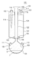
- Reference numeral 100 in Figs. 1 to 3 denotes a component separator according to an embodiment of the present invention.
- the component separator 100 basically includes an upper chamber 102 having an upper space therein, a lower chamber 104 having a lower space connected to the upper chamber 102 and communicating with the upper space, and the upper portion. It is provided in the chamber 102 includes an isolation means 120 to close between the upper chamber 102 and the lower chamber 104 to isolate the upper space and the lower space.
- Shapes of the upper chamber 102 and the lower chamber 104 are not limited, and a neck 106 may be formed between the upper chamber 102 and the lower chamber 104. As a result, it is easier to close between the upper chamber 102 and the lower chamber 104 by the isolation means 120.
- One or more lower ports 108 and 109 are formed in the wall of the lower chamber 104.
- One or more of the lower ports 108 and 109 may be installed, and in Example 1 of the present invention, two are installed.
- the lower ports 108 and 109 may be opened and closed by lower port stoppers 110 and 111, and as shown in FIG. 4, the lower ports 108 and 109 may be connected to separate instruments, for example, syringes 10 and 20.
- upper ports 112 and 113 may be formed in the upper chamber 102, and body fluids such as fat or blood may be supplied as separated substances through the upper ports 112 and 113.
- the upper ports 112 and 113 may also be opened and closed by upper port stoppers 116 and 117.
- One or more of the upper ports 112 and 113 may be installed, and in Example 1 of the present invention, two are installed.
- the upper chamber 102 is provided with a strainer 114 for filtering the separated object supplied from the upper port 112.
- the sieve 114 is not limited in shape as long as filtration of the separated material is possible.
- the isolating means 120, the isolation rod 122 is installed to be movable up and down with respect to the upper chamber 102, and formed at the end of the isolation rod 122, the upper chamber 102 and the lower A diaphragm 126 that closes between the chambers 104.
- the isolation rod Male threads 124 are formed on the outer circumferential surface of 122, and female threads 118 are formed in the upper chamber 102 to be screwed to the male threads 124.
- a handle 128 may be formed at an upper end of the isolation rod 122 to facilitate gripping the isolation rod 122.
- a lower portion of the upper chamber 102 has an inclined surface 103, and the diaphragm 126 abuts on the inclined surface 103. That is, the diaphragm 126 covers the upper side of the neck 106 to close between the upper chamber 102 and the lower chamber 104 as shown in FIG. 3. As a result, the upper chamber 102 and the lower chamber 104 are insulated from each other.
- the component separator 100 according to Embodiment 1 of the present invention is basically configured as described above. Hereinafter, the component separation process by the component separator 100 will be described.
- the method for isolating adipose derived stem cells will be described.
- the method such as inhalation.
- the obtained fat is subjected to decanting or centrifugation to remove water and obtain pure fat.
- the collagenase solution mixed with saline and collagenase is mixed with pure fat, and a process (incubation process) is performed to allow the stem cells existing between the adipocytes to be sufficiently released, and then decanted or After centrifugation, the target solution containing the stem cells collected at the lower side is charged to the component separator 100 through the upper port 112.
- the pure fat and the collagenase solution may be mixed and immediately placed in the component separator 100 to perform an incubation process in which the stem cells existing between the adipocytes are released in the component separator 100.
- the upper chamber 102 and the lower chamber 104 are in communication with each other.
- the upper ports 112 and 113 and the lower ports 108 and 109 of the component separator 100 are closed by the upper port stoppers 116 and 117 and the lower port stoppers 110 and 111, respectively.
- the component separator 100 is inserted into a centrifuge (not shown) to separate the target solution into layers.
- the upper chamber 102 and the lower chamber 104 are isolated using the isolation means 120, and then a syringe is inserted into the lower ports 108 and 109 of the upper chamber 102.
- the stem cell fraction located in the form of pellets (Pellet) at the bottom of the lower chamber 104 is suspended in the supernatant to extract the stem cell fluid.
- the lower ports 108 and 109 of the lower chamber 104 are located at the top of the lower chamber 104 where the pellets (stem cell fractions) are formed, rather than the bottom bottom of the lower chamber 104.
- the pellets stem cell fractions
- the stem cell solution obtained above is put into a new component separator 100 or the washed component separator 100, and the washing solution is supplied to the component separator 100 again.
- the component separator 100 into which the washing solution is charged is put back into the centrifuge and the layers are separated.
- the stem cell fraction (1) located in the form of pellets at the bottom of the lower chamber 104 is suspended in the supernatant (2) again to extract the stem cell fluid.
- the washing solution is injected again, and the stem cell solution is finally obtained by repeating the separation of the layers in a centrifuge 3 to 4 times.
- the upper chamber 102 is provided with a sieve 114 is installed, it does not need to go through a separate cell filtration process, and can reduce the extraction time and can prevent contamination by air and equipment .
- Plasma (6,9) containing a buffy coat layer (5,8) is called platelet rich plasma (PRP), plasma (6,9) that does not include a buffy coat layer (5,8) It is called PPP (Platelet Poor Plasma).
- PRP platelet rich plasma
- PPP Platelet Poor Plasma
- the upper chamber 102 and the lower chamber 104 are isolated using the isolation means 120.
- the connection pipette 24 is injected through the upper port 113 to include the entire buffy coat layer 5 from top to bottom in the plasma 6 in the upper chamber 102. Extract until (primary extraction). Thereafter, the whole plasma including the first extracted buffy coat layer 5 is charged into the new component separator 100 or the washed component separator 100. Thereafter, secondary centrifugation is performed as shown in FIG. 12.
- only plasma PRP, 9 is collected in the lower chamber 104, and the PRP including the buffy coat layer 8 is collected. In this case, as shown in FIG.
- bone marrow-derived stem cells first, bone marrow is extracted using a special bone marrow extraction needle at a site such as an iliac bone. Bone marrow extract has a similar pattern to blood, and can be extracted in the same manner as the above-mentioned blood component separation method.
- lymphocytes, immune cells, umbilical cord blood stem cells, etc. can also be separated using the specific gravity of the cells. That is, allogeneic cells or heterologous cells can be separated by the above method using specific gravity of cells.
- FIG. 15 to 17 show a component separator 132 of a variation of Embodiment 1 of the present invention.
- the component separator 132 is different from the component separator 100 in that one lower port 108 is installed in the lower chamber 104.
- FIG. 18 shows a component separator 134 of yet another variation of Embodiment 1 of the present invention.
- the component separator 134 can easily observe that the bottom part of the lower chamber 136 has a conical or pyramid-shaped collection part, and thus the collection of the pellet-shaped stem cell fractions located at the bottom of the lower chamber 136 is completed. have.
- Fig. 19 shows a component separator 138 of yet another variation of Embodiment 1 of the present invention.
- the component separator 138 has a collection part 142 of a conical or pyramidal shape protruding from the bottom of the lower chamber 140, so that the collection of the stem cell fraction of the pellet form located at the bottom of the lower chamber 140 It can be easily observed that it is completed.
- FIG. 20 and 21 show a component separator 200 according to Embodiment 2 of the present invention.
- the component separator 200 is basically the same as the component separator 100 of the first embodiment (a detailed description of the same parts will be omitted), but the diaphragm 226 is inserted into the neck 206 from the upper side to the lower side.
- the upper chamber 202 and the lower chamber 204 are separated from each other. Therefore, preferably, when the diaphragm 226 has a wedge shape, and the neck 206 has a shape corresponding to the diaphragm 226, insertion is easy and a closing effect is improved.
- 20 is an open state in which the diaphragm 226 is raised
- FIG. 21 is a closed state in which the diaphragm 226 is lowered and inserted into the neck 206.
- the component separator 300 is basically the same as the component separator 100 of the first embodiment, except that the lower port 308 is elongated to penetrate the upper chamber 302. Therefore, when connecting a syringe or the like as shown in Figure 23, the height of the lower port 308, the upper port 312 is similar, there is an advantage that it is convenient to use.
- the component separator 400 is basically the same as the component separator 100 of the first embodiment, except that the lower ports 408 and 409 extend long to penetrate the upper chamber 402. Therefore, when connecting a syringe or the like, the lower port (408, 409), the height of the upper port 412 has the advantage that it is convenient to use.
- the component separator 500 is basically the same as the component separator 100 of the first embodiment (a detailed description of the same parts will be omitted), but the extension pipes 509 and 515 may be installed at the lower ports 508 and 511 so that the upper chamber ( There is a difference extending upward of 502). Therefore, when connecting a syringe or the like, the upper port (512, 513), the height of the upper end of the extension pipe (509, 515) has the advantage that it is convenient to use.
- FIG. 27 and 28 show a component separator 700 according to Embodiment 6 of the present invention.
- the component separator 700 is basically the same as the component separator 200 of the second embodiment (a detailed description of the same parts is omitted), but the diaphragm 726 of the isolation rod 722 is connected to the lower chamber 704. There is a difference extending to the inside of.
- the isolation rod 722 is open when lowered, and as shown in FIG. 28, the isolation rod 722 is closed when raised.
- FIG. 29 and 30 show a component separator 800 according to Embodiment 7 of the present invention.
- the component separator 800 is basically the same as the component separator 100 of the first embodiment (a detailed description of the same parts is omitted), but the diaphragm 826 of the isolation rod 822 is the lower chamber 804. There is a difference extending to the inside of. Thus, as shown in FIG. 29, the isolation rod 822 is open when descending, and as shown in FIG. 30, the isolation rod 822 is closed when raised.
- FIG. 31 and 32 show a component separator 801 according to a modification of Embodiment 7 of the present invention.
- the component separator 801 is basically the same as the component separator 800 of the seventh embodiment (a detailed description of the same parts is omitted), but the lock nut 832 is installed above the isolation rod 822. Therefore, there is an advantage that the position of the isolation rod 822 is strongly fixed, so that its position does not change even in disturbance.
- FIG. 33 shows a component separator 900 according to Example 8.
- the component separator 900 is basically the same as the component separator 801 of the seventh embodiment (a detailed description of the same parts will be omitted), but the sieve 914 has an annular cross section inside the upper chamber 902. It is formed to be. Therefore, the volume inside the sieve 914 increases, thereby improving the filtration rate of the sieve 914 and having the advantage of being able to process a large amount of separated material at a time.
- the isolation means 1020 is different from the first through eighth embodiments. There is no neck between the upper chamber 1002 and the lower chamber 1004 and the diaphragm 1026 is enlarged to contact the inclined surface 1003 of the upper chamber 1002 so that the upper chamber 1002 and the lower chamber Isolation of the chamber 1004 is performed.
- the isolation rod 1022 on which the diaphragm 1026 is installed is integrally formed on the cover 1028, and the cover 1028 is fitted to the upper end of the upper chamber 1002 by the fitting or screwing. It is movable up and down with respect to the chamber 1002.
- the cover 1028 is lifted with respect to the upper chamber 1002 to open, or as shown in FIG. 35, the cover 1028 may be opened to the upper chamber 1002. It can be lowered to the closed state.
- the cover 1028 is provided with an upper port 1030, the lower surface of the cover 1028 is provided with a strainer 1032 for filtering the object to be supplied to the upper port 1030.
- an additional upper port 1024 may be formed in the cover 1028 so as to easily discharge the liquid inside the upper chamber 1002 to the outside.
- Lower ports 1008 and 1009 are formed in the lower chamber 1004, and the lower ports 1008 and 1009 can be opened and closed by lower port stoppers 1010 and 1011.
- the component separator 1100 is basically the same as the component separator 1000 of the ninth embodiment (a detailed description of the same parts is omitted), but there is a difference in the shape of the diaphragm 1126.
- the diaphragm 1126 of the component separator 1100 is formed to abut on the inner wall of the upper chamber 1102, and thus penetrates the diaphragm 1126 to allow the fluid to move in the open state as shown in FIG. Grooves 1138 are formed.
- the bottom surface of the diaphragm 1126 contacts the inclined surface 1103 of the upper chamber 1102, so that the upper chamber 1102 and the lower chamber 1104 are isolated.
- the component separator 1200 is basically the same as the component separator 1000 of the ninth embodiment (a detailed description of the same parts is omitted), but the isolation rod 1222 is formed by the rotating nut 1236 without using a cover. There is a difference to move in the vertical direction.
- the component separator 1200 is installed to allow the isolation rod 1222 to penetrate the upper portion of the upper chamber 1202.
- the rotation nut 1236 coupled to the rotation nut seat 1201 formed on the upper side of the upper chamber 1202 and the male screw 1225 formed on the outer circumferential surface of the isolation rod 1222 are screwed together. Therefore, the isolation rod 1222 is moved up and down by rotating the rotary nut 1236. Since the isolation rod 1222 must move up and down in a non-rotating state, a guide groove 1240 is formed at a side of the diaphragm 1226 formed at an end of the isolation rod 1222, and the guide groove 1240. Is in contact with the guide 1238 inside the upper chamber 1202 so that the diaphragm 1226 can only move up and down in a state in which rotational movement is constrained.
- Upper ports 1224 and 1230 are installed in the upper chamber 1202, and a strainer 1232 is installed inside the upper chamber 1202 to filter the object to be supplied to the upper port 1230.
- Lower ports 1208 and 1209 are formed in the lower chamber 1204, and the lower ports 1208 and 1209 can be opened and closed by lower port stoppers 1210 and 1211.
- the component separator 1300 is different from the embodiment in which the isolation means is the previous embodiment.
- the upper chamber 1302 has an upper extension tube 1306, and the lower chamber 1304 has a lower extension tube 1305.
- the upper extension tube 1306 is inserted into the lower extension tube 1305.
- An opening plug 1324 is fixed to the inside of the lower chamber 1304 by a frame 1322.
- the opening plug 1324 is a block having a slope to close the end of the upper extension tube 1306. Therefore, by communicating the upper chamber 1302 relative to the lower chamber 1304, it is possible to open and close the communication between the upper chamber 1302 and the lower chamber 1304. That is, as shown in FIG.
- the frame 1330 has a shape having two or more legs installed on the bottom surface of the lower chamber 1304.
- the component separator 1342 is basically the same as the component separator 1300 of Example 12 (a detailed description of the same parts is omitted), but the frame 1346 in which the opening plug 1349 is fixed to the lower chamber 1344. ), But is located inside the upper chamber 1302, and is installed around the opening of the upper extension tube 1306.
- FIG. 44 when the opening plug 1349 is spaced apart from the upper chamber 1302 and the lower chamber 1344 so as to contact the opening of the upper extension tube 1306, the upper chamber 1302 is disposed.
- the lower chamber 1344 are closed to each other. On the contrary, as shown in FIG.
- the opening plug 1349 functions as a stopper for limiting the separation distance between the upper chamber 1302 and the lower chamber 1344.
- the component separator 1348 is basically the same as the component separator 1342 of the thirteenth embodiment (a detailed description of the same parts is omitted), but a frame in which the opening plug 1352 is installed inside the upper chamber 1302. 1350 is fixed.
- the component separator 1354 is basically the same as the component separator 1300 of Example 12 (a detailed description of the same parts is omitted), but instead of the opening plug, the neck plug 1356 is inside the upper extension tube 1306. In the frame 1355. Accordingly, the lower extension tube 1305 is closed by contacting the neck plug 1356 while being inserted into the upper extension tube 1306. In addition, when the lower extension pipe 1305 is spaced apart from the neck plug 1356, the upper chamber 1302 and the lower chamber 1344 communicate with each other.
- the component separator 1400 is basically the same as the component separator 1300 of Example 12 (a detailed description of the same parts will be omitted), but the lower chamber has a lower chamber upper half 1405 and a lower chamber lower half 1404. There is a difference of).
- the neck 1406 is disposed between the upper chamber 1402 and the lower chamber upper half 1405, and the lower chamber lower half 1404 is formed by the lower chamber upper half 1405 and the gap adjusting unit 1407. It is fixed to adjust the gap up and down. Accordingly, the position of the lower chamber lower half 1404 may be moved up and down with respect to the lower chamber upper half 1405.
- the gap adjusting unit 1407 is formed so that the upper end of the lower chamber lower half (1404) and the lower end of the lower chamber upper half (1405) partially overlap each other, the length can be adjusted up and down by sliding or screwing Part.
- the component separator 1426 is basically the same as the component separator 1400 of the sixteenth embodiment (a detailed description of the same parts is omitted), but the opening plug 1424 is formed on the upper side of the neck 1406, that is, the upper chamber ( There is a difference disposed within 1402.
- the component separator 1434 is basically the same as the component separator 1400 of the seventeenth embodiment (a detailed description of the same parts is omitted), but the lower part of the lower chamber 1438 is divided into branches. There is a difference that is installed in).
Landscapes
- Health & Medical Sciences (AREA)
- Heart & Thoracic Surgery (AREA)
- General Health & Medical Sciences (AREA)
- Hematology (AREA)
- Life Sciences & Earth Sciences (AREA)
- Animal Behavior & Ethology (AREA)
- Public Health (AREA)
- Veterinary Medicine (AREA)
- Engineering & Computer Science (AREA)
- Anesthesiology (AREA)
- Biomedical Technology (AREA)
- Vascular Medicine (AREA)
- Pharmacology & Pharmacy (AREA)
- External Artificial Organs (AREA)
Abstract
La présente invention concerne un séparateur de composant qui : peut simplifier un procédé par comparaison à l'état de la technique; peut garantir la pureté d'un composant tel qu'une cellule souche ou du sang séparé(e) et similaire ; est apte à prévenir la pollution de l'air durant une étape de séparation de composant ; et possède une structure simple, le séparateur de composant comprenant : un compartiment supérieur ayant un espace supérieur à l'intérieur et un ou plusieurs orifice(s) supérieur(s) ; un compartiment inférieur qui est connecté au compartiment supérieur, et qui a un espace inférieur en communication avec l'espace supérieur et un ou plusieurs orifice(s) inférieur(s) ; et un moyen d'isolement placé dans le compartiment supérieur ou le compartiment inférieur afin de fermer un espace entre le compartiment supérieur et le compartiment inférieur, et l'isolement de l'espace supérieur vis-à-vis de l'espace inférieur.
Applications Claiming Priority (2)
| Application Number | Priority Date | Filing Date | Title |
|---|---|---|---|
| KR1020130049940A KR101343577B1 (ko) | 2013-05-03 | 2013-05-03 | 성분 분리기 |
| KR10-2013-0049940 | 2013-05-03 |
Publications (1)
| Publication Number | Publication Date |
|---|---|
| WO2014178570A1 true WO2014178570A1 (fr) | 2014-11-06 |
Family
ID=49988786
Family Applications (1)
| Application Number | Title | Priority Date | Filing Date |
|---|---|---|---|
| PCT/KR2014/003578 Ceased WO2014178570A1 (fr) | 2013-05-03 | 2014-04-24 | Séparateur de composant |
Country Status (2)
| Country | Link |
|---|---|
| KR (1) | KR101343577B1 (fr) |
| WO (1) | WO2014178570A1 (fr) |
Cited By (1)
| Publication number | Priority date | Publication date | Assignee | Title |
|---|---|---|---|---|
| CN114100871A (zh) * | 2021-11-21 | 2022-03-01 | 黄红 | 血液分离器具 |
Citations (4)
| Publication number | Priority date | Publication date | Assignee | Title |
|---|---|---|---|---|
| KR20100095952A (ko) * | 2009-02-23 | 2010-09-01 | 차의과학대학교 산학협력단 | 원심분리용 분리장치 및 원심 분리방법 |
| KR20100105282A (ko) * | 2009-03-16 | 2010-09-29 | 문상호 | 피알피 및 필러 추출과 피브린 생성을 위한 혈액분리 및 농축용기 |
| KR20110045479A (ko) * | 2009-10-27 | 2011-05-04 | 도병록 | 재생성 세포 추출 시스템 |
| KR20110080245A (ko) * | 2010-01-05 | 2011-07-13 | 방시열 | 일체형 분리장치 |
Family Cites Families (1)
| Publication number | Priority date | Publication date | Assignee | Title |
|---|---|---|---|---|
| US4268393A (en) | 1980-05-05 | 1981-05-19 | The Institutes Of Medical Sciences | Apparatus for centrifugal separation of platelet-rich plasma |
-
2013
- 2013-05-03 KR KR1020130049940A patent/KR101343577B1/ko active Active
-
2014
- 2014-04-24 WO PCT/KR2014/003578 patent/WO2014178570A1/fr not_active Ceased
Patent Citations (4)
| Publication number | Priority date | Publication date | Assignee | Title |
|---|---|---|---|---|
| KR20100095952A (ko) * | 2009-02-23 | 2010-09-01 | 차의과학대학교 산학협력단 | 원심분리용 분리장치 및 원심 분리방법 |
| KR20100105282A (ko) * | 2009-03-16 | 2010-09-29 | 문상호 | 피알피 및 필러 추출과 피브린 생성을 위한 혈액분리 및 농축용기 |
| KR20110045479A (ko) * | 2009-10-27 | 2011-05-04 | 도병록 | 재생성 세포 추출 시스템 |
| KR20110080245A (ko) * | 2010-01-05 | 2011-07-13 | 방시열 | 일체형 분리장치 |
Cited By (1)
| Publication number | Priority date | Publication date | Assignee | Title |
|---|---|---|---|---|
| CN114100871A (zh) * | 2021-11-21 | 2022-03-01 | 黄红 | 血液分离器具 |
Also Published As
| Publication number | Publication date |
|---|---|
| KR101343577B1 (ko) | 2013-12-20 |
Similar Documents
| Publication | Publication Date | Title |
|---|---|---|
| WO2011052946A2 (fr) | Système d'extraction de cellules régénératives | |
| WO2011052910A2 (fr) | Kit de séparation centrifuge, et procédé de séparation centrifuge utilisant ledit kit | |
| DE69503512D1 (de) | Zentrifugenspritzgerät und verfahren | |
| WO2017164467A1 (fr) | Culture de cellules souches mésenchymateuses pour la prévention ou le traitement d'une maladie immunitaire ou d'une maladie inflammatoire et procédé de préparation associé | |
| WO2013141436A1 (fr) | Récipient pour la centrifugation du sang | |
| WO2018097540A9 (fr) | Kit à ajout de milieu de culture de cellules immunitaires sans sérum, méthode de culture de cellules immunitaires utilisant ledit kit, culture de cellules immunitaires sans sérum obtenue au moyen dudit kit ou de ladite méthode de culture, et composition cosmétique comprenant ladite culture | |
| WO2016072821A1 (fr) | Composition pour l'induction de la différenciation d'adipocyte contenant un exosome dérivé de cellules souches, la régénération de tissus adipeux, et la décoloration de la peau ou l'atténuation des rides | |
| WO2014168409A1 (fr) | Récipient pour séparation du sang permettant d'extraire les plaquettes en vue d'une auto-transfusion | |
| KR101306455B1 (ko) | 줄기세포 분리 키트 | |
| WO2014178570A1 (fr) | Séparateur de composant | |
| WO2014168311A1 (fr) | Séparateur de composants | |
| WO2019103313A2 (fr) | Dispositif pour centrifugation de composants sanguins | |
| WO2013094819A1 (fr) | Dispositif de séparation du sang | |
| KR101749932B1 (ko) | 지방조직 유래 기질혈관분획 분리용 키트 및 이를 이용한 지방조직 유래 기질혈관분획의 분리 방법 | |
| WO2020256520A1 (fr) | Procédé de production d'exosomes par stimulation électrique | |
| WO2016006788A1 (fr) | Fonction favorisant la repousse des poils des cellules souches de petites tailles et son utilisation | |
| WO2017213305A1 (fr) | Cuve pour centrifugeuse et procédé d'isolation de svf utilisant celle-ci. | |
| KR101489264B1 (ko) | 줄기세포 분리 키트 및 줄기세포 분리 방법 | |
| WO2011062313A1 (fr) | Procédé pour la séparation de cellules souches | |
| WO2015037845A1 (fr) | Séparateur de constituants | |
| WO2021045567A1 (fr) | Composition de prévention ou de traitement des maladies des glandes salivaires en utilisant une vésicule dérivée de cellules | |
| WO2016006850A1 (fr) | Récipient de séparation de cellules, système de séparation de cellules et procédé de séparation de cellules | |
| WO2019156353A1 (fr) | Bouchon d'évacuation de jus, ensemble d'évacuation de jus et centrifugeuse | |
| WO2023055222A1 (fr) | Composition comprenant des composants dérivés de milieu de culture de cellules souches pluripotentes induites, et ses utilisations | |
| WO2013051816A9 (fr) | Système d'application d'une thérapie cellulaire destinée à traiter des imperfections de la peau, et unité de récolte de cellules, unité de pulvérisation, et unité d'atomisation de celles-ci |
Legal Events
| Date | Code | Title | Description |
|---|---|---|---|
| 121 | Ep: the epo has been informed by wipo that ep was designated in this application |
Ref document number: 14792090 Country of ref document: EP Kind code of ref document: A1 |
|
| NENP | Non-entry into the national phase |
Ref country code: DE |
|
| 122 | Ep: pct application non-entry in european phase |
Ref document number: 14792090 Country of ref document: EP Kind code of ref document: A1 |