WO2014181419A1 - 可変焦点レンズ - Google Patents
可変焦点レンズ Download PDFInfo
- Publication number
- WO2014181419A1 WO2014181419A1 PCT/JP2013/062998 JP2013062998W WO2014181419A1 WO 2014181419 A1 WO2014181419 A1 WO 2014181419A1 JP 2013062998 W JP2013062998 W JP 2013062998W WO 2014181419 A1 WO2014181419 A1 WO 2014181419A1
- Authority
- WO
- WIPO (PCT)
- Prior art keywords
- medium
- elastic film
- space
- focus lens
- tension
- Prior art date
- Legal status (The legal status is an assumption and is not a legal conclusion. Google has not performed a legal analysis and makes no representation as to the accuracy of the status listed.)
- Ceased
Links
Images


Classifications
-
- G—PHYSICS
- G02—OPTICS
- G02B—OPTICAL ELEMENTS, SYSTEMS OR APPARATUS
- G02B3/00—Simple or compound lenses
- G02B3/12—Fluid-filled or evacuated lenses
- G02B3/14—Fluid-filled or evacuated lenses of variable focal length
-
- G—PHYSICS
- G02—OPTICS
- G02B—OPTICAL ELEMENTS, SYSTEMS OR APPARATUS
- G02B27/00—Optical systems or apparatus not provided for by any of the groups G02B1/00 - G02B26/00, G02B30/00
- G02B27/0025—Optical systems or apparatus not provided for by any of the groups G02B1/00 - G02B26/00, G02B30/00 for optical correction, e.g. distorsion, aberration
Definitions
- the present invention relates to a variable focus lens.
- Patent Document 1 and Non-Patent Document 1 below describe a variable focus lens having a configuration in which an elastic film is disposed at a boundary portion between a first liquid and a second liquid.
- the refractive index of the first liquid is different from the refractive index of the second liquid, and the elastic film is used to maintain the boundary surface shape of these two liquids.
- variable focus lens by applying pressure to one of the liquids (for example, the second liquid), the curvature of the elastic film (that is, the curvature of the interface shape between the two liquids) can be changed.
- the refractive power (so-called lens power) can be adjusted.
- the specific gravity (or density) of the first liquid and the second liquid having different refractive indexes it is difficult to make the specific gravity (or density) of the first liquid and the second liquid having different refractive indexes completely equal.
- the density difference between the two liquids in a certain temperature range can be brought close to 0, but usually the density difference becomes large in a different temperature range.
- An object of the present invention is to provide a variable focus lens capable of exhibiting high lens performance.
- Another object of the present invention is to provide a variable focus lens capable of maintaining the lens performance even when the lens diameter is increased.
- the present invention has a configuration described in any of the following items.
- the housing is configured such that light can pass along the optical axis direction of the lens,
- the said accommodating part is equipped with the 1st space arranged along the said optical axis direction, and the 2nd space,
- the first elastic film is disposed between the first space and the second space, and is extended in a direction intersecting the optical axis direction, whereby the first space and the second space are It is configured to partition between The first space is filled with the first medium,
- the second space is filled with the second medium,
- the refractive indexes of the first medium and the second medium are different from each other,
- the first elastic film is disposed between the first medium and the second medium,
- the first elastic film is configured to be elastically deformable by a pressure difference between the first medium and the second medium
- the drive unit is configured to change the curvature of the first elastic film by changing the pressure or volume of the first medium or
- the drive unit causes a pressure difference between the first medium and the second medium by changing the pressure or volume of the first medium or the second medium, and as a result, changes the curvature of the first elastic film. Can do.
- the first tension applying unit is A holding portion for holding an outer periphery of the first elastic membrane; An isotropic tensile stress is generated in the first elastic film by pressing the vicinity of the outer periphery of the first elastic film held by the holding portion substantially uniformly along the optical axis direction.
- (Item 4) Item 4.
- the accommodating portion further includes a third space,
- the third space is disposed at a position along the optical axis direction with respect to the first space and the second space,
- the second elastic film is disposed between the second space and the third space, and is extended in a direction intersecting the optical axis direction, whereby the second space, the third space, It is configured to partition between The third space is filled with the third medium,
- the refractive index of the third medium is different from the refractive index of the first medium or the second medium
- the second elastic film is disposed between the second medium and the third medium,
- the second elastic film is configured to be elastically deformable by a pressure difference between the second medium and the third medium
- the drive unit is configured to change the curvature of the second elastic film by changing the pressure or volume of the second medium or the third medium, 5.
- the variable focus lens according to any one of items 1 to 4, wherein the second tension applying unit is configured to apply iso
- the drive unit causes a pressure difference between the second medium and the third medium by changing the pressure or volume of the second medium or the third medium, and as a result, changes the curvature of the second elastic film. Can do.
- (Item 9) A projection apparatus comprising the variable focus lens according to any one of items 1 to 7.
- the present invention has the above-described configuration, it is possible to provide a variable focus lens that can exhibit high lens performance even at low lens power. Furthermore, according to the present invention, it is possible to provide a large aperture variable focus lens having high lens performance.
- FIG. 1 is a schematic cross-sectional view of a variable focus lens according to a first embodiment of the present invention. It is explanatory drawing which expanded the principal part of FIG. It is explanatory drawing of the isotropic tension
- the vertical axis of the graph (b) represents the root mean square of the difference between the ideal wavefront and the wavefront estimated by the finite element method (so-called wavefront aberration), and the horizontal axis represents the lens refractive power.
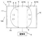
- the lens according to the present embodiment includes a housing unit 1, a first elastic film 2, a first medium 3, a second medium 4, a driving unit 5, and a first tension applying unit 6.
- the housing part 1 is configured such that light can pass along the direction of the optical axis 100 of the lens (indicated by a dashed line in FIG. 1).
- the storage unit 1 includes a first window portion 11 and a second window portion 12 that are spaced apart from each other in the optical axis direction.
- the 1st window part 11 and the 2nd window part 12 are made transparent in the part through which light passes, and light can pass in the direction of the optical axis 100 through these window parts 11 and 12 by this.
- the term “transparent” means that the amount of attenuation with respect to light in the wavelength band targeted for lens action is as small as practically necessary.
- the lens of this embodiment is for visible light unless otherwise specified.
- the accommodating part 1 of this embodiment is made into the cylindrical shape by which both ends were closed by the 1st window part 11 and the 2nd window part 12, it is not restricted to this, For example, appropriate shapes, such as a rectangular tube shape, are used. Selectable.
- the housing unit 1 includes a first space 13 and a second space 14 arranged along the direction of the optical axis 100. More specifically, the accommodating part 1 of this embodiment is provided with the cylindrical side wall 15 which connects these between the 1st window part 11 and the 2nd window part 12, By these, the accommodating part 1 is provided. An internal space is formed in the interior. As described later, the first space 13 and the second space 14 are formed by partitioning the internal space by the first elastic film 2. In other words, the first space 13 and the second space 14 are partitioned by the first elastic film 2.
- the first elastic film 2 is disposed between the first space 13 and the second space 14, and is extended in a direction intersecting the optical axis 100 direction (a direction orthogonal in this example). Thereby, as described above, the first elastic film 2 partitions the first space 13 and the second space 14.
- the first space 13 is filled with the first medium 3, and the second space 14 is filled with the second medium 4.
- first space 13 and the second space 14 it is not essential that the first space 13 and the second space 14 be sealed, and either the first medium 3 or the second medium 4 is substantially open to the outside ( That is, it may be in a state under atmospheric pressure).
- the medium to be pressurized or depressurized is preferably sealed so that the pressure can be varied.
- the refractive indexes of the first medium 3 and the second medium 4 are different from each other.
- the specific gravity (density) of the first medium 3 and the second medium 4 is preferably as equal as possible in the temperature range assumed for use.
- a combination of such media can be selected as appropriate.
- a combination of PDMS (Poly-Dimethyl-Siloxane) and pure water can be used.
- the refractive indices are 1.40 and 1.33 mm, respectively. Either of them may be the first medium 3.
- liquid is used as the first medium 3 and the second medium 4.
- these media can be in the form of a sol, a gel, or an elastic body in addition to the liquid.
- any medium can be used as long as the change in the pressing force received from the drive unit 5 can be applied to the interface between the two media to bulge the interface toward one side.
- the first elastic film 2 is disposed between the first medium 3 and the second medium 4.
- a material of the first elastic film 2 for example, a highly transparent silicone resin can be used.
- the first elastic film 2 is not limited to a silicone resin, and may be any material that can be elastically deformed by a pressure difference between the first medium 3 and the second medium 4.
- the first elastic film 2 of this example is formed in a thin circular sheet shape.
- the first medium 3 and the second medium 4 are in direct contact with the first elastic film 2, but these media are in contact with the first elastic film 2 indirectly through some pressure transmission material. You may do it. In short, it is sufficient that the pressure from the first medium 3 or the second medium 4 can be transmitted to the first elastic film 2.
- the drive unit 5 is configured to change the curvature of the first elastic film 2 by changing the pressure or volume of the first medium 3 or the second medium 4. More specifically, the drive unit 5 of this example is connected to the second space 14 and is configured to be able to increase or decrease the pressure of the second medium 4.
- achieving the drive part 5 is not restrict
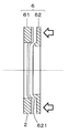
- the first tension applying unit 6 is configured to apply isotropic tension to the first elastic film 2. More specifically, the first tension applying unit 6 of this example includes a holding unit 61 that holds the outer periphery of the first elastic membrane 2, and an area near the outer periphery of the first elastic membrane 2 that is held by the holding unit 61. And a pressing portion 62 that generates isotropic tensile stress on the first elastic film 2 by pressing substantially uniformly along the direction of the optical axis 100 (see FIG. 2). 2 exaggerates the thickness of the elastic film 2, and the overall dimensions are not accurate.
- the outer periphery of the first elastic film 2 and the holding portion 61 can be fixed by, for example, welding of the contact surface by plasma treatment or adhesion with an adhesive.
- the pressing portion 62 has a protruding portion 621 that protrudes in the direction of the optical axis 100.
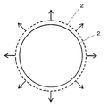
- isotropic tension is applied to the first elastic film 2.
- Stress see FIG. 3 can be applied.
- FIG. 3 schematically illustrates the direction of the tensile stress, and the dimensions are not accurate.
- the protruding portion 621 of this example has an annular shape when viewed from the optical axis direction.
- the pressure difference between the first medium 3 and the second medium 4 is set to 0 [Pa]. That is, both hydrostatic pressures are made equal.
- the first elastic membrane 2 in this state is indicated by a two-dot chain line in FIG.
- the conventional variable focus lens due to the subtle difference in density between the two media, unintended minute deformation may occur in the elastic film between the media due to the influence of gravity. For this reason, the conventional lens may not exhibit sufficient optical performance particularly when the lens power is small (that is, when the curvature of the film is small).
- the first tension applying unit 6 applies isotropic tensile stress to the first elastic film 2. Even if there is a small density difference between the two media 4, the deformation of the first elastic film 2 can be kept small. That is, in this embodiment, there is an advantage that the optical performance of the lens can be improved particularly when the lens power is small by reducing the influence of gravity due to the density difference between the media. Further, since the influence of gravity as described above becomes conspicuous as the diameter of the lens increases, the lens of this embodiment also has an advantage that it is suitable for increasing the diameter. That is, according to the present embodiment, it is possible to provide a variable aperture lens having a large aperture and high performance.
- the drive unit 5 pressurizes the second medium 4. Then, a pressure difference is generated between the first medium 3 and the second medium 4, and the boundary between both moves to a position where the pressures of both the media are balanced.
- the shape of the first elastic film 2 can be expanded into a dome shape or a paraboloid shape.
- the lens power can be changed.
- the first elastic film 2 is bulged in the left direction in the figure, but the first elastic film 2 is bulged in the opposite direction by setting the pressure to the second medium 4 to a negative pressure. You can also.
- the hydrostatic pressure of the second medium 4 is changed by the drive unit 5, but the shape of the first elastic film 2 is changed by pressurization or decompression of the first medium 3. It is also possible to change.
- the hydrostatic pressure of each medium is changed by moving the position of the holding unit 61 that holds the first elastic film 2 along the optical axis direction (for example, moving left and right in FIG. 1).
- a configuration in which the shape of the first elastic film 2 is changed is also possible. This has the advantage that the size of the entire lens including the drive unit can be reduced.
- the color dispersion characteristics of the first medium 3 and the color dispersion characteristics of the second medium 4 can be different characteristics. This has the advantage that the chromatic aberration of the entire lens can be reduced.
- the lens of the present embodiment since the tension is applied to the first elastic film 2 in advance, the speed until the deformed elastic film 2 returns to the initial position can be improved. For this reason, according to this lens, there is an advantage that the moving cycle of the lens focal position can be speeded up.
- First medium pure water (refractive index 1.33, density 0.997 g / cm 3 )
- Second medium PDMS liquid (poly-dimethyl-siloxane liquid) (refractive index 1.40, density 0.975 g / cm 3 )
- First elastic membrane circular sheet with a diameter of 30 mm, thickness 0.1 mm, Young's modulus 5 MPa, Poisson's ratio 0.45
- the ⁇ marks indicate the results when no pre-tension is applied to the film (that is, the comparative example), and the ⁇ marks indicate the results when the pre-tension is applied to the film (that is, this example).
- the external pressure means the pressure applied to the second medium 4 by the drive unit 5.
- the vertical axis of FIG. 4A shows how far the point where the displacement in the elastic film is the largest is located from the center of the film (that is, the center of the light beam or the optical axis). The closer to 0, the more the interface shape symmetry is maintained (that is, good optical performance can be obtained).
- the same refractive power can be obtained, for example, when the refractive power is 0.3 [1 / m], in the example of no tension (marked with a circle in the figure), the deviation amount is about 0.7 mm, but there is tension (see FIG. In the example of the middle ⁇ mark), the amount of deviation is suppressed to as low as about 0.1 mm. Therefore, according to the present embodiment, it can be seen that a variable lens having high optical performance can be provided even in a low refractive power region.
- the vertical axis in FIG. 4B shows the root-means-square-error (RMSE) of the difference between the ideal wavefront and the wavefront estimated by the finite element method (so-called wavefront aberration).
- RMSE root-means-square-error
- variable focus lens according to the second embodiment further includes a second elastic film 7, a third medium 8, and a second tension applying unit 9.
- the accommodating portion 1 of the present embodiment further includes a third space 16.
- the third space 16 is arranged at a position along the direction of the optical axis 100 with respect to the first space 13 and the second space 14. More specifically, the third space is a region surrounded by the second elastic film 7, the second window portion 12, and the side wall 15.
- the second elastic film 7 is disposed between the second space 14 and the third space 16 and is extended in a direction intersecting the optical axis 100 (specifically, an orthogonal direction), whereby the second space 14 and the third space 16 are partitioned.
- the second elastic film 7 is disposed between the second medium 4 and the third medium 8. Further, the second elastic film 7 is configured to be elastically deformable by a pressure difference between the second medium 4 and the third medium 8.
- the color dispersion characteristics of the first elastic film 2 and the color dispersion characteristics of the second elastic film 7 are different characteristics.
- the second elastic film 7 can be configured in the same manner as the first elastic film 2.
- the third space 16 is filled with the third medium 8.
- the refractive index of the third medium 8 is different from the refractive index of the first medium 3 and / or the second medium 4 so that the lens action can be exhibited.
- the third medium 8 can be configured in the same manner as the first medium 3 and the second medium 4.
- the drive unit 5 is configured to change the curvature of the second elastic film 7 by changing the pressure or volume of the second medium 4 or the third medium 8. More specifically, the drive unit 5 of this example can drive both the first elastic film 2 and the second elastic film 7 by changing the pressure of the second medium 4.
- the initial pressures of the first medium 3 and the third medium 4 are the same, and the pressure difference between these two media and the second medium 4 is equal.
- the second tension applying unit 9 is configured to apply isotropic tension to the second elastic film 7.
- the tension applied to the first elastic film 2 and the tension applied to the second elastic film 7 have different magnitudes.
- the second tension applying unit 9 is configured in the same manner as the first tension applying unit 6.
- variable focus lens of the second embodiment As in the first embodiment, the first elastic film 2 and the second elastic film 7 in the initial state are in a flat state (state indicated by a two-dot chain line in FIG. 5). .
- the drive unit 5 varies the pressure of the second medium 4. Thereby, the curvature of the 1st elastic film 2 and the 2nd elastic film 7 can be changed.
- both the first elastic film 2 and the second elastic film 7 (more specifically, the interface between the three media) exhibit the lens action. Therefore, in the second embodiment, a variable focus lens having a plurality of single lenses can be provided.
- the tension applied to the first elastic film 2 and the tension applied to the second elastic film 7 have different magnitudes. Furthermore, in this embodiment, the initial pressures of the first medium 3 and the third medium 4 are the same, and the pressure difference between these two media and the second medium 4 is equal. Then, the refractive power generated in both elastic films changes according to the tension applied to each film (see the solid line in FIG. 5). Thus, in 2nd Embodiment, the several lens from which refractive power differs can be provided by adjusting the tension
- the chromatic dispersion characteristics of the first elastic film 2 and the chromatic dispersion characteristics of the second elastic film 7 are different from each other, so that the chromatic aberration of the entire lens can be reduced. There is also.
- the film thickness and the distance between the elastic films in this embodiment can be appropriately designed so as to be suitable for a zoom lens.
- the pressure of the second medium 4 is changed.
- the pressure of the other medium may be changed.
- a drive unit for changing the medium may be prepared separately, or the drive unit described above may be shared.
- the color dispersion characteristics in the first elastic film 2 and the color dispersion characteristics in the second elastic film 7 are different characteristics, but the same characteristics are possible.
- tensile_strength provision part 9 was comprised similarly to the 1st tension
- the second elastic film and the third medium are further provided.
- a structure in which a larger number of elastic films and mediums are stacked is also possible.
- a complicated lens configuration can be realized. Since the configuration of the elastic film and the like in this case can be understood from the above, detailed description is omitted.
- An imaging device such as a camera or a projection device such as a liquid crystal projector can be configured using the lens of each embodiment described above.
- each of the embodiments and examples is merely an example, and does not indicate a configuration essential to the present invention.
- the configuration of each part is not limited to the above as long as the gist of the present invention can be achieved.
- tension is applied to the elastic film using the pressing portion 62.
- the present invention is not limited to this.
- the elastic film is attached to a frame having a higher thermal expansion coefficient than the elastic film and heated. After applying tension to the elastic membrane, it is also possible to maintain the tension applied to the elastic membrane by attaching this frame to another highly rigid support.
- the refractive index of each medium described above can be variously set according to the design purpose of the lens.
Landscapes
- Physics & Mathematics (AREA)
- General Physics & Mathematics (AREA)
- Optics & Photonics (AREA)
- Mechanical Light Control Or Optical Switches (AREA)
- Lenses (AREA)
Abstract
Description
収容部と、第1弾性膜と、第1媒質と、第2媒質と、駆動部と、第1張力付与部とを備えており、
前記収容部は、レンズの光軸方向に沿って光が通過可能とされており、
かつ、前記収容部は、前記光軸方向に沿って配列された第1空間と、第2空間とを備えており、
前記第1弾性膜は、前記第1空間と前記第2空間との間に配置され、かつ、前記光軸方向に交差する方向に延長されることによって、前記第1空間と前記第2空間との間を仕切る構成とされており、
前記第1空間には、前記第1媒質が充填されており、
前記第2空間には、前記第2媒質が充填されており、
前記第1媒質と前記第2媒質の屈折率は、互いに異なるものとされており、
前記第1弾性膜は、前記第1媒質と前記第2媒質との間に配置されており、
かつ、前記第1弾性膜は、前記第1媒質と前記第2媒質との間の圧力差によって弾性変形可能な構成とされており、
前記駆動部は、前記第1媒質又は前記第2媒質の圧力又は体積を変動させることにより、前記第1弾性膜の曲率を変化させる構成となっており、
前記第1張力付与部は、前記第1弾性膜に対して、等方的な張力を付与する構成とされている
ことを特徴とする可変焦点レンズ。
前記第1媒質及び前記第2媒質は、いずれも液体である
ことを特徴とする項目1に記載の可変焦点レンズ。
前記第1張力付与部は、
前記第1弾性膜の外周を保持する保持部と、
前記保持部に保持された状態の前記第1弾性膜の外周近傍を、前記光軸方向に沿ってほぼ一様に押圧することによって、前記第1弾性膜に等方的な引張応力を発生させる押圧部と
を備える項目1又は2に記載の可変焦点レンズ。
前記第1媒質の色分散特性と、前記第2媒質の色分散特性とは、異なる特性とされている
項目1~3のいずれか1項に記載の可変焦点レンズ。
第2弾性膜と、第3媒質と、第2張力付与部とをさらに備えており、
前記収容部は、第3空間をさらに備えており、
前記第3空間は、前記第1空間及び第2空間に対して、前記光軸方向に沿う位置に配置されており、
前記第2弾性膜は、前記第2空間と前記第3空間との間に配置され、かつ、前記光軸方向に交差する方向に延長されることによって、前記第2空間と前記第3空間との間を仕切る構成とされており、
前記第3空間には、前記第3媒質が充填されており、
前記第3媒質の屈折率は、第1媒質又は前記第2媒質の屈折率とは異なるものとされており、
前記第2弾性膜は、前記第2媒質と前記第3媒質との間に配置されており、
かつ、前記第2弾性膜は、前記第2媒質と前記第3媒質との間の圧力差によって弾性変形可能な構成とされており、
前記駆動部は、前記第2媒質又は第3媒質の圧力又は体積を変動させることにより、前記第2弾性膜の曲率を変化させる構成となっており、
前記第2張力付与部は、前記第2弾性膜に対して、等方的な張力を付与する構成とされている
項目1~4のいずれか1項に記載の可変焦点レンズ。
前記第1弾性膜に付与された前記張力と、前記第2弾性膜に付与された前記張力とは、異なる大きさとされている
項目5に記載の可変焦点レンズ。
前記第1弾性膜における色分散特性と、前記第2弾性膜における色分散特性とは、異なる特性とされている
項目5又は6に記載の可変焦点レンズ。
項目1~7のいずれか1項に記載された可変焦点レンズを備えた撮像装置。
項目1~7のいずれか1項に記載された可変焦点レンズを備えた投射装置。
以下、本発明の第1実施形態に係る可変焦点レンズ(以下単に「レンズ」と略称することがある)を、添付の図面に基づいて説明する。本実施形態のレンズは、収容部1と、第1弾性膜2と、第1媒質3と、第2媒質4と、駆動部5と、第1張力付与部6とを備えている。
次に、本実施形態に係る可変焦点レンズの動作について説明する。
前記した第1実施形態の可変焦点レンズの性能を検証するため、有限要素解析法(finite element analysis)を用いてシミュレーションを行った。条件は以下のとおりである。
第2媒質:PDMS液(poly-dimethyl-siloxane liquid)(屈折率1.40、密度0.975g/cm3)
第1弾性膜:直径30mmの円形シート状、厚さ0.1mm、ヤング率5MPa、ポアソン比0.45
次に、本発明の第2実施形態に係る可変焦点レンズを、図5を参照しながら説明する。この第2実施形態の説明においては、前記した第1実施形態のレンズと基本的に共通する構成要素については、同一符号を付すことによって、説明の煩雑を避ける。
第2実施形態の可変焦点レンズにおいても、第1実施形態と同様に、初期状態の第1弾性膜2及び第2弾性膜7は、平坦状態(図5において二点鎖線で示す状態)にある。ついで、第2実施形態の可変焦点レンズでは、駆動部5によって第2媒質4の圧力を変動させる。これにより、第1弾性膜2及び第2弾性膜7の曲率を変化させることができる。第2実施形態のレンズにおいては、第1弾性膜2及び第2弾性膜7の両方(より具体的には三つの媒質間の界面)がレンズ作用を発揮する。したがって、第2実施形態では、複数の単レンズを有する可変焦点レンズを提供することができる。
Claims (9)
- 収容部と、第1弾性膜と、第1媒質と、第2媒質と、駆動部と、第1張力付与部とを備えており、
前記収容部は、レンズの光軸方向に沿って光が通過可能とされており、
かつ、前記収容部は、前記光軸方向に沿って配列された第1空間と、第2空間とを備えており、
前記第1弾性膜は、前記第1空間と前記第2空間との間に配置され、かつ、前記光軸方向に交差する方向に延長されることによって、前記第1空間と前記第2空間との間を仕切る構成とされており、
前記第1空間には、前記第1媒質が充填されており、
前記第2空間には、前記第2媒質が充填されており、
前記第1媒質と前記第2媒質の屈折率は、互いに異なるものとされており、
前記第1弾性膜は、前記第1媒質と前記第2媒質との間に配置されており、
かつ、前記第1弾性膜は、前記第1媒質と前記第2媒質との間の圧力差によって弾性変形可能な構成とされており、
前記駆動部は、前記第1媒質又は前記第2媒質の圧力又は体積を変動させることにより、前記第1弾性膜の曲率を変化させる構成となっており、
前記第1張力付与部は、前記第1弾性膜に対して、等方的な張力を付与する構成とされている
ことを特徴とする可変焦点レンズ。 - 前記第1媒質及び前記第2媒質は、いずれも液体である
ことを特徴とする請求項1に記載の可変焦点レンズ。 - 前記第1張力付与部は、
前記第1弾性膜の外周を保持する保持部と、
前記保持部に保持された状態の前記第1弾性膜の外周近傍を、前記光軸方向に沿ってほぼ一様に押圧することによって、前記第1弾性膜に等方的な引張応力を発生させる押圧部と
を備える請求項1又は2に記載の可変焦点レンズ。 - 前記第1媒質の色分散特性と、前記第2媒質の色分散特性とは、異なる特性とされている
請求項1~3のいずれか1項に記載の可変焦点レンズ。 - 第2弾性膜と、第3媒質と、第2張力付与部とをさらに備えており、
前記収容部は、第3空間をさらに備えており、
前記第3空間は、前記第1空間及び第2空間に対して、前記光軸方向に沿う位置に配置されており、
前記第2弾性膜は、前記第2空間と前記第3空間との間に配置され、かつ、前記光軸方向に交差する方向に延長されることによって、前記第2空間と前記第3空間との間を仕切る構成とされており、
前記第3空間には、前記第3媒質が充填されており、
前記第3媒質の屈折率は、第1媒質又は前記第2媒質の屈折率とは異なるものとされており、
前記第2弾性膜は、前記第2媒質と前記第3媒質との間に配置されており、
かつ、前記第2弾性膜は、前記第2媒質と前記第3媒質との間の圧力差によって弾性変形可能な構成とされており、
前記駆動部は、前記第2媒質又は第3媒質の圧力又は体積を変動させることにより、前記第2弾性膜の曲率を変化させる構成となっており、
前記第2張力付与部は、前記第2弾性膜に対して、等方的な張力を付与する構成とされている
請求項1~4のいずれか1項に記載の可変焦点レンズ。 - 前記第1弾性膜に付与された前記張力と、前記第2弾性膜に付与された前記張力とは、異なる大きさとされている
請求項5に記載の可変焦点レンズ。 - 前記第1弾性膜における色分散特性と、前記第2弾性膜における色分散特性とは、異なる特性とされている
請求項5又は6に記載の可変焦点レンズ。 - 請求項1~7のいずれか1項に記載された可変焦点レンズを備えた撮像装置。
- 請求項1~7のいずれか1項に記載された可変焦点レンズを備えた投射装置。
Priority Applications (5)
| Application Number | Priority Date | Filing Date | Title |
|---|---|---|---|
| EP13883877.6A EP2995976A4 (en) | 2013-05-09 | 2013-05-09 | Varifocal lens |
| JP2015515689A JP6143274B2 (ja) | 2013-05-09 | 2013-05-09 | 可変焦点レンズ |
| CN201380076359.0A CN105209939B (zh) | 2013-05-09 | 2013-05-09 | 可变焦距透镜 |
| PCT/JP2013/062998 WO2014181419A1 (ja) | 2013-05-09 | 2013-05-09 | 可変焦点レンズ |
| US14/889,819 US20160103253A1 (en) | 2013-05-09 | 2013-05-09 | Varifocal lens |
Applications Claiming Priority (1)
| Application Number | Priority Date | Filing Date | Title |
|---|---|---|---|
| PCT/JP2013/062998 WO2014181419A1 (ja) | 2013-05-09 | 2013-05-09 | 可変焦点レンズ |
Publications (1)
| Publication Number | Publication Date |
|---|---|
| WO2014181419A1 true WO2014181419A1 (ja) | 2014-11-13 |
Family
ID=51866923
Family Applications (1)
| Application Number | Title | Priority Date | Filing Date |
|---|---|---|---|
| PCT/JP2013/062998 Ceased WO2014181419A1 (ja) | 2013-05-09 | 2013-05-09 | 可変焦点レンズ |
Country Status (5)
| Country | Link |
|---|---|
| US (1) | US20160103253A1 (ja) |
| EP (1) | EP2995976A4 (ja) |
| JP (1) | JP6143274B2 (ja) |
| CN (1) | CN105209939B (ja) |
| WO (1) | WO2014181419A1 (ja) |
Cited By (8)
| Publication number | Priority date | Publication date | Assignee | Title |
|---|---|---|---|---|
| GB2542638A (en) * | 2015-09-28 | 2017-03-29 | Adiens Ltd | An adjustable fluid-filled lens assembly and method for assembling the same |
| CN107690597A (zh) * | 2015-06-03 | 2018-02-13 | 韦伯斯特资本有限责任公司 | 具有可变孔的光学设备 |
| US10151961B2 (en) | 2016-12-29 | 2018-12-11 | Facebook Technologies, Llc | Switchable bragg gratings for chromatic error correction of pancharatnam berry phase (PBP) components |
| US10248001B1 (en) * | 2016-11-16 | 2019-04-02 | Facebook Technologies, Llc | Varifocal structure comprising a liquid lens structure in optical series with a liquid crystal lens in a head-mounted display |
| US10379419B1 (en) | 2016-11-23 | 2019-08-13 | Facebook Technologies, Llc | Focus adjusting pancharatnam berry phase liquid crystal lenses in a head-mounted display |
| US10901205B1 (en) | 2016-08-09 | 2021-01-26 | Facebook Technologies, Llc | Focus adjusting liquid crystal lenses in a head-mounted display |
| KR20210104171A (ko) * | 2017-03-22 | 2021-08-24 | 매직 립, 인코포레이티드 | 동적 시야 가변 초점 디스플레이 시스템 |
| JP2021535430A (ja) * | 2018-08-22 | 2021-12-16 | オプトチューン アーゲー | 配向非依存性コマ補償液体レンズ |
Families Citing this family (4)
| Publication number | Priority date | Publication date | Assignee | Title |
|---|---|---|---|---|
| WO2016003367A1 (en) * | 2014-07-02 | 2016-01-07 | Heptagon Micro Optics Pte. Ltd. | Techniques for reducing distortion of optical beam shaping elements |
| US10690921B1 (en) * | 2018-03-26 | 2020-06-23 | Facebook Technologies, Llc | Apparatuses, systems, and methods for coordinated lens adjustments |
| CN108873377A (zh) * | 2018-07-17 | 2018-11-23 | 安徽启慧信息科技有限公司 | 一种多用眼镜 |
| EP3910398B1 (en) * | 2020-05-13 | 2023-11-01 | Essilor International | Three-state optical article and method for controlling same |
Citations (8)
| Publication number | Priority date | Publication date | Assignee | Title |
|---|---|---|---|---|
| JPH01302301A (ja) * | 1988-05-31 | 1989-12-06 | Asahi Optical Co Ltd | 液体封入光学素子 |
| JP2000507415A (ja) * | 1996-03-26 | 2000-06-13 | マンネスマン・アクチエンゲゼルシャフト | 工業用途のための光電式結像システム |
| JP2004233945A (ja) | 2003-01-29 | 2004-08-19 | Futofumi Nagao | 光学装置 |
| JP2011128492A (ja) * | 2009-12-21 | 2011-06-30 | Canon Inc | 液体レンズ |
| JP2011158826A (ja) * | 2010-02-03 | 2011-08-18 | Canon Inc | 屈折力可変素子 |
| JP2012093471A (ja) * | 2010-10-26 | 2012-05-17 | Canon Inc | 形状可変素子及びそれを有するレンズ装置 |
| JP2012520477A (ja) * | 2009-03-13 | 2012-09-06 | オプトチューン アクチェンゲゼルシャフト | レンズシステム |
| JP2013068875A (ja) * | 2011-09-26 | 2013-04-18 | Panasonic Corp | 可変焦点レンズおよびその製造方法ならびに可変焦点レンズを備えた撮像装置 |
Family Cites Families (8)
| Publication number | Priority date | Publication date | Assignee | Title |
|---|---|---|---|---|
| US2300251A (en) * | 1941-01-23 | 1942-10-27 | Bausch & Lomb | Variable focus lens |
| US3161718A (en) * | 1961-07-12 | 1964-12-15 | William Kurasch | Variable power fluid lens |
| JPS5536857A (en) * | 1978-09-06 | 1980-03-14 | Matsushita Electric Ind Co Ltd | Vari-focal lens |
| US5684637A (en) * | 1995-07-19 | 1997-11-04 | Floyd; Johnnie E. | Fluid filled and pressurized lens with flexible optical boundary having variable focal length |
| GB9805977D0 (en) * | 1998-03-19 | 1998-05-20 | Silver Joshua D | Improvements in variable focus optical devices |
| US7948683B2 (en) * | 2006-05-14 | 2011-05-24 | Holochip Corporation | Fluidic lens with manually-adjustable focus |
| US8699141B2 (en) * | 2009-03-13 | 2014-04-15 | Knowles Electronics, Llc | Lens assembly apparatus and method |
| CN101950078B (zh) * | 2010-09-07 | 2012-03-28 | 华中科技大学 | 基于逆压电效应的可变焦双液体透镜 |
-
2013
- 2013-05-09 US US14/889,819 patent/US20160103253A1/en not_active Abandoned
- 2013-05-09 JP JP2015515689A patent/JP6143274B2/ja active Active
- 2013-05-09 CN CN201380076359.0A patent/CN105209939B/zh not_active Expired - Fee Related
- 2013-05-09 WO PCT/JP2013/062998 patent/WO2014181419A1/ja not_active Ceased
- 2013-05-09 EP EP13883877.6A patent/EP2995976A4/en not_active Withdrawn
Patent Citations (8)
| Publication number | Priority date | Publication date | Assignee | Title |
|---|---|---|---|---|
| JPH01302301A (ja) * | 1988-05-31 | 1989-12-06 | Asahi Optical Co Ltd | 液体封入光学素子 |
| JP2000507415A (ja) * | 1996-03-26 | 2000-06-13 | マンネスマン・アクチエンゲゼルシャフト | 工業用途のための光電式結像システム |
| JP2004233945A (ja) | 2003-01-29 | 2004-08-19 | Futofumi Nagao | 光学装置 |
| JP2012520477A (ja) * | 2009-03-13 | 2012-09-06 | オプトチューン アクチェンゲゼルシャフト | レンズシステム |
| JP2011128492A (ja) * | 2009-12-21 | 2011-06-30 | Canon Inc | 液体レンズ |
| JP2011158826A (ja) * | 2010-02-03 | 2011-08-18 | Canon Inc | 屈折力可変素子 |
| JP2012093471A (ja) * | 2010-10-26 | 2012-05-17 | Canon Inc | 形状可変素子及びそれを有するレンズ装置 |
| JP2013068875A (ja) * | 2011-09-26 | 2013-04-18 | Panasonic Corp | 可変焦点レンズおよびその製造方法ならびに可変焦点レンズを備えた撮像装置 |
Non-Patent Citations (2)
| Title |
|---|
| LIHUI WANG; HIROMASA OKU; MASATOSHI ISHIKAWA: "Variable-focus lens with 30mm optical aperture based on liquid-membrane-liquid structure", APPL. PHYS. LETT., vol. 102, 2013, pages 131111 |
| See also references of EP2995976A4 * |
Cited By (22)
| Publication number | Priority date | Publication date | Assignee | Title |
|---|---|---|---|---|
| CN107690597A (zh) * | 2015-06-03 | 2018-02-13 | 韦伯斯特资本有限责任公司 | 具有可变孔的光学设备 |
| CN107690597B (zh) * | 2015-06-03 | 2020-05-19 | 韦伯斯特资本有限责任公司 | 具有可变孔的光学设备 |
| GB2542638A (en) * | 2015-09-28 | 2017-03-29 | Adiens Ltd | An adjustable fluid-filled lens assembly and method for assembling the same |
| RU2721305C2 (ru) * | 2015-09-28 | 2020-05-18 | Эдленз Лтд | Заполненный текучей средой регулируемый линзовый блок и способ его сборки |
| US10901205B1 (en) | 2016-08-09 | 2021-01-26 | Facebook Technologies, Llc | Focus adjusting liquid crystal lenses in a head-mounted display |
| US10248001B1 (en) * | 2016-11-16 | 2019-04-02 | Facebook Technologies, Llc | Varifocal structure comprising a liquid lens structure in optical series with a liquid crystal lens in a head-mounted display |
| US10371872B1 (en) | 2016-11-16 | 2019-08-06 | Facebook Technologies, Llc | Varifocal structure comprising a liquid lens structure in optical series with a liquid crystal lens in a head-mounted display and method of adjusting an optical power of the varifocal structure |
| US10539829B1 (en) | 2016-11-16 | 2020-01-21 | Facebook Technologies, Llc | Method of selecting a state of a switchable half waveplate and selecting an optical power of a liquid lens structure in optical series with a liquid crystal lens in a head-mounted display |
| US11009765B1 (en) | 2016-11-23 | 2021-05-18 | Facebook Technologies, Llc | Focus adjusting pancharatnam berry phase liquid crystal lenses in a head-mounted display |
| US10379419B1 (en) | 2016-11-23 | 2019-08-13 | Facebook Technologies, Llc | Focus adjusting pancharatnam berry phase liquid crystal lenses in a head-mounted display |
| US10690930B1 (en) | 2016-12-29 | 2020-06-23 | Facebook Technologies, Llc | Optical structure comprising a structure of stacked optical elements that receives circularly polarized light having a first handedness and outputs circularly polarized light having a second handedness to a focal point |
| US10317772B1 (en) | 2016-12-29 | 2019-06-11 | Facebook Technologies, Llc | Switchable bragg gratings for chromatic error correction of pancharatnam berry phase (PBP) components |
| US10935804B1 (en) | 2016-12-29 | 2021-03-02 | Facebook Technologies, Llc | Optical structure comprising a plurality of stacked optical elements that receive light having a first polarization and output light having a second polarization to a focal point |
| US10151961B2 (en) | 2016-12-29 | 2018-12-11 | Facebook Technologies, Llc | Switchable bragg gratings for chromatic error correction of pancharatnam berry phase (PBP) components |
| US11231593B1 (en) | 2016-12-29 | 2022-01-25 | Facebook Technologies, Llc | Optical structure comprising a plurality of optical elements each configured to convert received light having a first polarization into output light having a second polarization focused to a common focal point |
| KR20210104171A (ko) * | 2017-03-22 | 2021-08-24 | 매직 립, 인코포레이티드 | 동적 시야 가변 초점 디스플레이 시스템 |
| KR102438618B1 (ko) * | 2017-03-22 | 2022-08-30 | 매직 립, 인코포레이티드 | 동적 시야 가변 초점 디스플레이 시스템 |
| US12007573B2 (en) | 2017-03-22 | 2024-06-11 | Magic Leap, Inc. | Dynamic field of view variable focus display system |
| JP2021535430A (ja) * | 2018-08-22 | 2021-12-16 | オプトチューン アーゲー | 配向非依存性コマ補償液体レンズ |
| JP2024045375A (ja) * | 2018-08-22 | 2024-04-02 | オプトチューン スウィツァランド アーゲー | 配向非依存性コマ補償液体レンズ |
| JP7500542B2 (ja) | 2018-08-22 | 2024-06-17 | オプトチューン スウィツァランド アーゲー | 配向非依存性コマ補償液体レンズ |
| US12546916B2 (en) | 2018-08-22 | 2026-02-10 | Optotune Ag | Orientation independent coma compensating liquid lens |
Also Published As
| Publication number | Publication date |
|---|---|
| EP2995976A1 (en) | 2016-03-16 |
| CN105209939B (zh) | 2017-09-22 |
| JPWO2014181419A1 (ja) | 2017-02-23 |
| CN105209939A (zh) | 2015-12-30 |
| EP2995976A4 (en) | 2017-03-29 |
| US20160103253A1 (en) | 2016-04-14 |
| JP6143274B2 (ja) | 2017-06-07 |
Similar Documents
| Publication | Publication Date | Title |
|---|---|---|
| JP6143274B2 (ja) | 可変焦点レンズ | |
| Chen et al. | Electrically tunable lenses: a review | |
| ES2989061T3 (es) | Conjunto de lente para estabilización óptica de imagen y ajuste de enfoque | |
| US8605361B2 (en) | Fluidic lens with reduced optical aberration | |
| US5973852A (en) | Variable power fluid lens | |
| US6891679B2 (en) | Optical system and image pickup apparatus | |
| US9703019B2 (en) | Adaptive optic and acoustic devices | |
| JP6389273B2 (ja) | 短距離光拡大モジュール、眼鏡、ヘルメットおよび仮想現実システム | |
| US20110038028A1 (en) | Optical Imaging Lens systems and components | |
| JP2012518197A5 (ja) | ||
| KR102824232B1 (ko) | 응력 분산 지지 구조체를 가지는 광학 요소 | |
| JP2009543152A (ja) | ズーム光学系、並びにそれを備えたカメラ及びデバイス | |
| WO2009099585A1 (en) | Mechanical lenses | |
| KR20130091201A (ko) | 가변 초점 렌즈 | |
| KR102274385B1 (ko) | 매크로 렌즈 | |
| CN101470256A (zh) | 变焦镜头 | |
| WO2021052044A1 (zh) | 镜头模组及电子设备 | |
| JP2021521483A5 (ja) | ||
| Fuh et al. | Characterization of adjustable fluidic lenses and capability for aberration correction of defocus and astigmatism | |
| Santiago-Alvarado et al. | Simulating the functioning of variable focus length liquid-filled lenses using the finite element method (FEM) | |
| Zhao et al. | A miniaturized camera objective with 2X optical zoom | |
| Wang et al. | PDMS gel-type adaptive lens array driven by piezoelectric ceramics | |
| Zhang et al. | The analysis of the wavefront aberration caused by the gravity of the tunable-focus liquid-filled membrane lens | |
| Wang et al. | An adaptive achromatic doublet design by double variable focus lenses | |
| JPH0467001A (ja) | 焦点距離可変レンズ及びレンズの焦点距離可変方法 |
Legal Events
| Date | Code | Title | Description |
|---|---|---|---|
| 121 | Ep: the epo has been informed by wipo that ep was designated in this application |
Ref document number: 13883877 Country of ref document: EP Kind code of ref document: A1 |
|
| WWE | Wipo information: entry into national phase |
Ref document number: 2013883877 Country of ref document: EP |
|
| ENP | Entry into the national phase |
Ref document number: 2015515689 Country of ref document: JP Kind code of ref document: A |
|
| WWE | Wipo information: entry into national phase |
Ref document number: 14889819 Country of ref document: US |
|
| NENP | Non-entry into the national phase |
Ref country code: DE |