WO2014181446A1 - Système de communication, dispositif de commande et procédé de commande - Google Patents
Système de communication, dispositif de commande et procédé de commande Download PDFInfo
- Publication number
- WO2014181446A1 WO2014181446A1 PCT/JP2013/063091 JP2013063091W WO2014181446A1 WO 2014181446 A1 WO2014181446 A1 WO 2014181446A1 JP 2013063091 W JP2013063091 W JP 2013063091W WO 2014181446 A1 WO2014181446 A1 WO 2014181446A1
- Authority
- WO
- WIPO (PCT)
- Prior art keywords
- communication device
- communication
- signal
- terminal
- measurement signal
- Prior art date
- Legal status (The legal status is an assumption and is not a legal conclusion. Google has not performed a legal analysis and makes no representation as to the accuracy of the status listed.)
- Ceased
Links
Images






Classifications
-
- H—ELECTRICITY
- H04—ELECTRIC COMMUNICATION TECHNIQUE
- H04W—WIRELESS COMMUNICATION NETWORKS
- H04W24/00—Supervisory, monitoring or testing arrangements
- H04W24/10—Scheduling measurement reports ; Arrangements for measurement reports
Definitions
- the present invention relates to a communication system, a control device, and a control method.
- LTE Long Term Evolution
- LTE-A Long Term Evolution-Advanced
- an object of the present invention is to provide a communication system, a control device, and a control method capable of measuring communication quality while suppressing interference.
- FIG. 1A is a diagram of an example of a communication system according to the first embodiment.
- 1B is a diagram illustrating an example of a signal flow in the communication system illustrated in FIG. 1A.
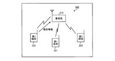
- FIG. 2A is a diagram (part 1) illustrating an example of a communication system according to a second embodiment.
- FIG. 2B is a diagram (part 2) illustrating an example of a communication system according to the second embodiment.
- FIG. 2C is a diagram (part 3) illustrating an example of a communication system according to the second embodiment.
- FIG. 2D is a diagram (part 4) illustrating an example of a communication system according to the second embodiment.
- FIG. 3 is a diagram illustrating an example of correspondence information between the waveform pattern parameter and the transmission power of the measurement signal.
- FIG. 4A is a diagram illustrating an example of a configuration of a base station.
- 4B is a diagram illustrating an example of a signal flow in the configuration of the base station illustrated in FIG. 4A.
- FIG. 5A is a diagram illustrating an exemplary configuration of a terminal.
- FIG. 5B is a diagram illustrating an example of a signal flow in the configuration of the terminal illustrated in FIG. 5A.
- FIG. 6 is a flowchart illustrating an example of processing by the base station.
- FIG. 7 is a flowchart illustrating an example of processing by the terminal.
- FIG. 8 is a sequence diagram illustrating an example of a measurement operation in the communication system.
- FIG. 9 is a diagram illustrating an example of PSS transmission timing.
- FIG. 10 is a diagram illustrating an example of grouping of transmission powers of measurement signals.
- FIG. 11 is a flowchart illustrating an example of processing for determining the transmission power of a measurement signal.
- FIG. 1A is a diagram of an example of a communication system according to the first embodiment.
- 1B is a diagram illustrating an example of a signal flow in the communication system illustrated in FIG. 1A.
- the communication system 100 according to the first embodiment includes a first communication device 110, a second communication device 120, a third communication device 130, and a control device 140.
- the first communication device 110, the second communication device 120, and the third communication device 130 are devices capable of wireless communication.
- the control device 140 can communicate with the second communication device 120 and the third communication device 130 via wireless communication by the first communication device 110.
- the control device 140 can communicate with the first communication device 110 outside the first communication device 110. It may be a device.
- the first communication device 110 includes a transmission unit 111 and a control device 140.
- the transmission unit 111 wirelessly transmits a synchronization signal.
- the synchronization signal is a periodic signal having a predetermined waveform pattern for another communication device to synchronize wireless communication with the first communication device 110.
- At least one of the second communication device 120 and the third communication device 130 is a communication device that is wirelessly connected to the first communication device 110.
- both the second communication device 120 and the third communication device 130 are wirelessly connected to the first communication device 110, but one of the second communication device 120 and the third communication device 130 is
- the wireless communication device may be wirelessly connected to another communication device that can communicate with the first communication device 110.
- the second communication device 120 and the third communication device 130 can directly communicate with each other wirelessly.
- the control device 140 includes a control unit 141 and a reception unit 142.
- the control unit 141 has a waveform pattern orthogonal to the synchronization signal transmitted by the transmission unit 111 and the measurement signal having the same frequency band as the synchronization signal transmitted by the transmission unit 111 in accordance with the transmission timing of the synchronization signal by the transmission unit 111. Control to wirelessly transmit from the second communication device 120 is performed.
- the control unit 141 transmits a measurement signal from the second communication device 120 by transmitting a control signal including a parameter capable of deriving a waveform pattern orthogonal to the synchronization signal transmitted by the transmission unit 111 to the second communication device 120. Let it transmit wirelessly. Further, the control unit 141 may further notify the second communication device 120 of the frequency of the measurement signal. The control unit 141 may also transmit a control signal including a parameter that can derive a waveform pattern orthogonal to the synchronization signal transmitted by the transmission unit 111 to the third communication device 130.
- the receiving unit 142 receives from the third communication device 130 the reception result of the measurement signal wirelessly transmitted from the second communication device 120 by the third communication device 130 under the control of the control unit 141.
- the second communication device 120 includes a reception unit 121 and a transmission unit 122.
- the receiving unit 121 receives a control signal transmitted from the control device 140. Then, the reception unit 121 outputs the parameters included in the received control signal to the transmission unit 122.
- the transmission unit 122 generates a measurement signal whose waveform pattern is orthogonal to the synchronization signal wirelessly transmitted by the first communication device 110 based on the parameter output from the reception unit 121. Then, the transmission unit 122 wirelessly transmits the generated measurement signal in accordance with the transmission timing of the synchronization signal by the first communication device 110.
- the reception unit 131 outputs the reception result of the measurement signal to the transmission unit 132.
- the reception result of the measurement signal can be, for example, the reception power (reception power) of the measurement signal in the third communication device 130.
- the reception result of the measurement signal may be a propagation loss (path loss) based on a comparison between the transmission power of the measurement signal in the second communication device 120 and the reception power of the measurement signal in the third communication device 130.
- the transmission unit 132 transmits the reception result output from the reception unit 131 to the control device 140. Accordingly, the control device 140 can obtain a reception result of the measurement signal wirelessly transmitted from the second communication device 120 in the third communication device 130. For this reason, the communication quality between the 2nd communication apparatus 120 and the 3rd communication apparatus 130 can be measured.
- the second communication device 120 and the second communication device 120 are connected to the second communication device 120 using the measurement signal of the same radio resource (time and frequency) as the synchronization signal wirelessly transmitted by the first communication device 110.
- the communication quality with the three communication devices 130 can be measured. Thereby, it is possible to measure the communication quality between the second communication device 120 and the third communication device 130 without vacating radio resources for the measurement signal. For this reason, the compression of the radio
- the cross-correlation value between the synchronization signal and the measurement signal can be obtained by using the measurement signal whose waveform pattern is orthogonal to the synchronization signal. Can be lowered. For this reason, the interference by the measurement signal with respect to the synchronous signal which the 1st communication apparatus 110 transmits can be suppressed.
- the communication quality between the second communication device 120 and the third communication device 130 can be measured while suppressing interference with the communication of the first communication device 110.
- the transmission power of the measurement signal from the second communication device 120 may be determined by the control device 140.
- the second communication device 120, the third communication device 130, and the control device 140 share correspondence information that associates the waveform pattern parameter notified by the control device 140 with the transmission power of the measurement signal.
- the control device 140 selects a parameter corresponding to the determined transmission power among the parameters capable of deriving a waveform pattern orthogonal to the synchronization signal transmitted by the transmission unit 111 based on the correspondence information. Then, control device 140 transmits a control signal including the selected parameter to second communication device 120 and third communication device 130.
- the transmission unit 122 of the second communication device 120 wirelessly transmits the measurement signal with the transmission power corresponding to the parameter included in the control signal received by the reception unit 121 based on the correspondence information.
- the receiving unit 131 of the third communication device 130 specifies the transmission power corresponding to the parameter included in the control signal transmitted from the control device 140 based on the correspondence information. Then, the reception unit 131 calculates the propagation loss of the measurement signal based on the comparison between the specified transmission power and the reception power of the received measurement signal.
- the transmission power of the measurement signal can be notified to the second communication device 120 and the third communication device 130 using the parameter for notifying the waveform pattern of the measurement signal. Thereby, the information amount of a control signal can be reduced.
- the control device 140 may calculate the propagation loss of the measurement signal based on a comparison between the determined transmission power of the measurement signal and the reception power transmitted as the reception result from the third communication device 130. .
- the base station 210 transmits PSS (Primary Synchronization Signal) periodically (every 5 ms in the latest 3GPP LTE specifications).
- PSS Primary Synchronization Signal
- the waveform pattern of the PSS transmitted by the base station 210 is associated with the cell ID of the base station 210, for example.
- SSS Secondary Synchronization Signal
- both PSS and SSS are transmitted on the radio downlink.
- the physical layer ID (PCI: Physical Cell ID) of each radio cell (Cell) of the base station is associated with both PSS and SSS, and the terminal receives both PSS and SSS so that they are transmitted. It becomes possible to know the PCI of the wireless cell.
- one base station forms a plurality of radio cells, and one radio cell is composed of only Pcell (Primary Cell), or further composed of Pcell and one or more Scell (Secondary Cell).
- the first terminal 221, the second terminal 222, and the third terminal 223 are wireless communication terminals capable of wireless communication with the base station 210.
- the wireless communication terminal is also called UE (User Equipment) or MS (Mobile Station).
- the first terminal 221, the second terminal 222, and the third terminal 223 can synchronize wireless communication with the base station 210 by detecting the PSS transmitted from the base station 210.
- a PSS is transmitted for each radio cell of a base station, and the parameter values for determining the PSS signal waveform are set to be different between PSSs transmitted between the radio cells. The same value may be used between different wireless cells.
- the first terminal 221 and the second terminal 222 can directly communicate with each other wirelessly under moderate control by the base station 210.
- the first communication device 110 and the control device 140 illustrated in FIGS. 1A and 1B can be realized by the base station 210, for example.
- the second communication device 120 illustrated in FIGS. 1A and 1B can be realized by the first terminal 221, for example.
- the third communication device 130 illustrated in FIGS. 1A and 1B can be realized by the second terminal 222, for example.
- the base station 210 determines whether direct communication between the first terminal 221 and the second terminal 222 is possible. For this purpose, the base station 210 performs control to cause the measurement signal from the first terminal 221 to be wirelessly transmitted and the measurement signal from the first terminal 221 to be received by the second terminal 222 as illustrated in FIG. 2B.
- the second terminal 222 wirelessly transmits to the base station 210 report information indicating a reception result at the second terminal 222 of the measurement signal wirelessly transmitted from the first terminal 221.
- Base station 210 determines whether direct communication between first terminal 221 and second terminal 222 is possible based on the report information received from second terminal 222.
- the base station 210 determines that direct communication is possible, the base station 210 transmits a control signal to the first terminal 221 and the second terminal 222, as shown in FIG. 2 Direct communication with the terminal 222 is started.
- the band in the direct communication between the first terminal 221 and the second terminal 222 may be a band used by the base station 210 with the terminal, for example.
- the base station 210 causes the first terminal 221 to transmit a measurement signal whose waveform pattern is orthogonal to the PSS transmitted by the base station 210 at the same time and frequency as the PSS transmitted by the base station 210.
- the communication quality between the first terminal 221 and the second terminal 222 can be measured without vacating radio resources for the measurement signal. For this reason, it is possible to suppress the compression of radio resources due to the measurement signal.
- the cross-correlation value between the PSS of the base station 210 and the measurement signal can be lowered. For this reason, the interference by the measurement signal with respect to the PSS transmitted from the base station 210 can be suppressed. For example, interference by the measurement signal from the first terminal 221 when the third terminal 223 detects and synchronizes the PSS transmitted by the base station 210 can be suppressed.
- FIG. 3 is a diagram illustrating an example of correspondence information between the waveform pattern parameter and the transmission power of the measurement signal.
- the base station 210, the first terminal 221 and the second terminal 222 store, for example, correspondence information 300 shown in FIG. 3 in respective memories.
- the parameter u of the correspondence information 300 is a parameter that can derive a waveform pattern in which the waveform pattern is orthogonal to the PSS transmitted by the base station 210.
- the transmission power (P1, P2,...) Of the correspondence information 300 is the transmission power of the measurement signal (for example, the absolute value of the transmission power).
- the base station 210 determines the transmission power of the measurement signal
- the base station 210 selects the parameter u corresponding to the determined power from the parameters u of the correspondence information 300. Then, the base station 210 transmits a control signal including the selected parameter u to the first terminal 221 and the second terminal 222.
- the control signal for example, PDCCH (Physical Downlink Control Channel: physical downlink control channel) or E-PDCCH (Enhanced-Physical Downlink Control Channel: extended physical downlink control channel) can be used.
- PDSCH Physical Downlink Shared Channel
- Layer2 Mac Layer
- the first terminal 221 generates and transmits a parameter pattern PSS based on the parameter u included in the control signal received from the base station 210 and the above equation (1) as a measurement signal. In addition, the first terminal 221 sets the transmission power of the measurement signal as the transmission power corresponding to the parameter u in the correspondence information 300.
- the second terminal 222 generates a replica signal having a waveform pattern based on the parameter u included in the control signal received from the base station 210 and the above equation (1). Then, the second terminal 222 detects the measurement signal transmitted from the first terminal 221 by comparing the received signal with the replica signal. Further, the second terminal 222 acquires the transmission power corresponding to the parameter u in the correspondence information 300, and compares it with the received power of the detected measurement signal, thereby causing a path loss between the first terminal 221 and the second terminal 222. Is calculated. Then, the second terminal 222 transmits report information including the calculated path loss to the base station 210. This report information may include other radio measurement results.
- the report information is transmitted to the base station 210 using PUSCH (Physical Uplink Shared Channel) used in the radio uplink.
- PUSCH Physical Uplink Shared Channel
- PUCCH Physical Uplink Control Channel
- Various radio parameters of PUSCH or PUCCH to be used and resource information of PUSCH or PUCCH used by the terminal (information indicating the frequency position of PRB: Physical Resource Block directly or indirectly) is previously determined using the PDSCH. Or notified to the terminal using PDCCH or E-PDCCH.
- PRB information indicating the frequency location of the Physical Resource Block directly or indirectly
- information indicating directly or indirectly that the PUSCH or PUCCH is used for the purpose of transmitting report information may be included.
- the transmission power of the measurement signal can be notified to the first terminal 221 and the second terminal 222 using the parameter u for notifying the waveform pattern of the measurement signal. Thereby, the information amount of a control signal can be reduced.
- the parameter u may not be directly associated with the transmission power, but may be information that associates the parameter u with the difference between the transmission power of the reference signal from the base station 210.
- the reference signal is a reference signal transmitted by the base station 210, and is, for example, CRS (cell specific reference signal) or CSI RS.
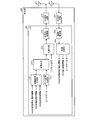
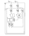
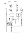
- FIG. 4A is a diagram illustrating an example of a configuration of a base station.
- 4B is a diagram illustrating an example of a signal flow in the configuration of the base station illustrated in FIG. 4A.
- the base station 210 shown in FIGS. 2A to 2D can be realized by the base station 400 shown in FIGS. 4A and 4B, for example.
- the base station 400 includes a control signal generation unit 411, a data signal generation unit 412, multiplexing units 413 and 414, an encoding / modulation unit 415, an RF transmission circuit 416, and a transmission antenna 417.
- the base station 400 includes a reception antenna 421, an RF reception circuit 422, a demodulation / decoding unit 423, and a demultiplexing unit 424.
- the control signal generation unit 411, the data signal generation unit 412, the multiplexing units 413 and 414, the encoding / modulation unit 415, the demodulation / decoding unit 423, and the demultiplexing unit 424 are, for example, LSI 401 (Large Scale Integration: large scale integrated circuit). Can be realized.
- the control signal generation unit 411 generates a control signal for the base station 400 to wirelessly transmit.
- the control signal generated by the control signal generation unit 411 includes, for example, PSS transmission instruction information, PSS transmission stop instruction information, PSS detection instruction information, and other control information.
- the control signal generation unit 411 outputs the generated control signal to the multiplexing unit 413.
- the data signal generator 412 generates a data signal for the base station 400 to wirelessly transmit based on the input user data. Then, the data signal generation unit 412 outputs the generated data signal to the multiplexing unit 413.
- the encoding / modulation unit 415 encodes and modulates the signal output from the multiplexing unit 414.
- the encoding by the encoding / modulation unit 415 includes, for example, addition of a parity code for error correction and generation of a code string having an encoding rate that provides required characteristics. Then, encoding / modulation section 415 outputs a signal obtained by encoding and modulation to RF transmission circuit 416.
- the demodulation / decoding unit 423 performs demodulation and decoding of the signal output from the RF reception circuit 422.
- Demodulation / decoding section 423 outputs a signal obtained by demodulation and decoding to demultiplexing section 424.
- the demultiplexing unit 424 demultiplexes the signal output from the demodulation / decoding unit 423. Then, the demultiplexing unit 424 outputs each demultiplexed signal.
- Each signal output from the demultiplexing unit 424 includes, for example, PSS reception result report information, other control information, user data, and the like.
- the 1A and 1B can be realized by an RF transmission circuit 416 and a transmission antenna 417, for example.
- the control unit 141 shown in FIGS. 1A and 1B can be realized by, for example, a control signal generation unit 411, a multiplexing unit 413, a multiplexing unit 414, an encoding / modulation unit 415, an RF transmission circuit 416, and a transmission antenna 417. it can.
- the receiving unit 142 illustrated in FIGS. 1A and 1B can be realized by, for example, the receiving antenna 421, the RF receiving circuit 422, the demodulation / decoding unit 423, and the demultiplexing unit 424.
- FIG. 5A is a diagram illustrating an exemplary configuration of a terminal.
- FIG. 5B is a diagram illustrating an example of a signal flow in the configuration of the terminal illustrated in FIG. 5A.
- Each of first terminal 221 and second terminal 222 shown in FIGS. 2A to 2D can be realized by terminal 500 shown in FIGS. 5A and 5B, for example.
- the terminal 500 includes a data signal generation unit 511, a control signal generation unit 512, a multiplexing unit 513, a PSS generation unit 514, a switch 515, an encoding / modulation unit 516, an RF transmission circuit 517, and a transmission antenna. 518.
- Terminal 500 includes a receiving antenna 521, an RF receiving circuit 522, a demodulation / decoding unit 523, a demultiplexing unit 524, and a PSS detection unit 525.
- the data signal generation unit 511, the control signal generation unit 512, the multiplexing unit 513, the PSS generation unit 514, the switch 515, the encoding / modulation unit 516, the demodulation / decoding unit 523, the demultiplexing unit 524, and the PSS detection unit 525 are, for example, It can be realized by the LSI 501.
- the control signal generation unit 512 generates a control signal for the terminal 500 to wirelessly transmit.
- the control signal generated by the control signal generator 512 includes, for example, PSS reception result report information and other control information.
- the control signal generation unit 512 outputs the generated control signal to the multiplexing unit 513.
- the multiplexing unit 513 multiplexes the input pilot signal (or reference signal), the data signal output from the data signal generation unit 511, and the control signal output from the control signal generation unit 512. Then, multiplexing section 513 outputs a signal obtained by multiplexing to switch 515.
- the PSS generation unit 514 When the PSS transmission instruction information is output from the demultiplexing unit 524, the PSS generation unit 514 generates a PSS based on the PSS transmission instruction information. Specifically, the PSS generator 514 generates a waveform pattern PSS based on the parameter u included in the transmission instruction information and the above equation (1). Then, the PSS generation unit 514 outputs the generated PSS to the switch 515. Further, when the PSS transmission stop instruction information is output from the demultiplexing unit 524, the PSS generation unit 514 stops generating the PSS.
- the encoding / modulation unit 516 encodes and modulates the signal output from the switch 515.
- the encoding by the encoding / modulation unit 516 includes, for example, addition of a parity code for error correction, generation of a code string having an encoding rate that provides required characteristics, and the like. Then, encoding / modulation section 516 outputs a signal obtained by encoding and modulation to RF transmission circuit 517.
- the receiving antenna 521 receives a signal wirelessly transmitted from another communication device (for example, the base station 400). Then, the reception antenna 521 outputs the received signal to the RF reception circuit 522.
- the RF reception circuit 522 performs an RF reception process on the signal output from the reception antenna 521.
- the RF reception processing performed by the RF reception circuit 522 includes, for example, frequency conversion and analog to digital conversion.
- the RF reception circuit 522 outputs a signal obtained by the RF reception process to the demodulation / decoding unit 523 and the PSS detection unit 525.
- the demultiplexing unit 524 demultiplexes the signal output from the demodulation / decoding unit 523. Then, the demultiplexing unit 524 outputs each demultiplexed signal.
- Each signal output from the demultiplexing unit 524 includes, for example, PSS transmission instruction information, PSS transmission stop instruction information, PSS detection instruction information, other control information, user data, and the like.
- the demultiplexing unit 524 outputs the PSS transmission instruction information and the PSS transmission stop instruction information to the PSS generation unit 514. Further, the demultiplexing unit 524 outputs PSS detection instruction information to the PSS detection unit 525.
- the PSS detection unit 525 detects the PSS transmitted from the base station 400 from the signal output from the RF reception circuit 522. For example, the PSS detection unit 525 generates replica signals having a plurality of predetermined waveform patterns. Then, the PSS detection unit 525 detects the PSS transmitted as the measurement signal from the base station 400 by comparing the signal output from the RF reception circuit 522 with the replica signal.
- the PSS detection unit 525 when the PSS detection instruction information is output from the demultiplexing unit 524, the PSS detection unit 525, among the signals output from the RF reception circuit 522, the PSS transmitted as a measurement signal from another terminal 500. Detection is performed. For example, the PSS detector 525 generates a replica signal of a waveform pattern based on the parameter u included in the detection instruction information and the above equation (1). Then, the PSS detection unit 525 detects the PSS transmitted from the other terminal 500 as the measurement signal by comparing the signal output from the RF reception circuit 522 with the replica signal. Then, PSS detection section 525 outputs report information of the PSS reception result based on the PSS detection result to control signal generation section 512.
- 1A and 1B can be realized by, for example, the reception antenna 521, the RF reception circuit 522, the demodulation / decoding unit 523, and the demultiplexing unit 524.
- 1A and 1B is implemented by, for example, a PSS detection unit 525, a control signal generation unit 512, a multiplexing unit 513, a switch 515, an encoding / modulation unit 516, an RF transmission circuit 517, and a transmission antenna 518. can do.
- FIG. 6 is a flowchart illustrating an example of processing by the base station.
- the base station 400 executes, for example, each step shown in FIG. First, the base station 400 determines whether or not the first terminal 221 and the second terminal 222 are in the same cell (step S601), and the first terminal 221 and the second terminal 222 are in the same cell. (Step S601: No loop).
- step S601 when the first terminal 221 and the second terminal 222 are in the same cell (step S601: Yes), the base station 400 determines the waveform pattern and transmission power of the PSS transmitted by the first terminal 221. (Step S602). In step S602, the base station 400 determines a waveform pattern orthogonal to the PSS waveform pattern transmitted from the own station as the PSS waveform pattern transmitted from the first terminal 221.
- the base station 400 transmits PSS transmission instruction information to the first terminal 221 (step S603).
- the transmission instruction information includes the waveform pattern determined in step S602 and the parameter u indicating the transmission power.
- the base station 400 transmits the PSS detection instruction information from the first terminal 221 to the second terminal 222 (step S604).
- the detection instruction information includes the waveform pattern determined in step S602 and the parameter u indicating the transmission power. Note that the order of steps S603 and S604 may be changed.
- the base station 400 sets a timer for measuring a predetermined time (step S605).
- the base station 400 determines whether or not PSS reception result report information has been received from the second terminal 222 (step S606).
- the base station 400 determines whether or not the timer set in step S605 has expired (step S607).
- the base station 400 returns to step S606.
- step S607 when the set timer expires (step S607: Yes), the base station 400 transmits PSS transmission stop instruction information to the first terminal 221 (step S608), and ends a series of processing. In this case, the base station 400 does not start processing for causing direct communication between the first terminal 221 and the second terminal 222.
- step S606 when report information is received (step S606: Yes), the base station 400 transmits PSS transmission stop instruction information to the first terminal 221 (step S609).
- step S610 the base station 400 starts processing for direct communication between the first terminal 221 and the second terminal 222 based on the report information received in step S606 (step S610), and performs a series of processing. finish.
- the base station 400 compares the communication quality between the first terminal 221 and the second terminal 222 based on the report information received in step S606 with a threshold value, for example. And if the communication quality is less than a threshold value, the base station 400 does not start direct communication between the first terminal 221 and the second terminal 222.
- FIG. 7 is a flowchart illustrating an example of processing by the terminal.
- the terminal 500 executes, for example, each step shown in FIG. First, terminal 500 determines whether or not PSS transmission instruction information has been received from base station 400 (step S701). If transmission instruction information has not been received (step S701: No), terminal 500 determines whether or not PSS detection instruction information has been received from base station 400 (step S702). If the detection instruction information has not been received (step S702: No), the terminal 500 returns to step S701.
- step S702 when the detection instruction information is received (step S702: Yes), the terminal 500 sets a timer for measuring a predetermined time (step S703). Next, terminal 500 determines whether or not a PSS based on the received detection instruction information has been received from another terminal (step S704).
- the PSS based on the detection instruction information is a PSS having a waveform pattern derived from the parameter u included in the detection instruction information.
- step S704 when the PSS based on the detection instruction information is not received (step S704: No), the terminal 500 determines whether or not the timer set in step S703 has expired (step S705). If the timer has not expired (step S705: No), the terminal 500 returns to step S704. If the timer has expired (step S705: Yes), the terminal 500 returns to step S701.
- step S701 when transmission instruction information is received (step S701: Yes), terminal 500 starts transmission of PSS based on the received transmission instruction information (step S707).
- the PSS based on the transmission instruction information is a PSS having a waveform pattern derived from the parameter u included in the transmission instruction information.
- terminal 500 determines whether or not PSS transmission stop instruction information has been received from base station 400 (step S708), and waits until reception stop instruction information is received (step S708: No loop).
- step S708: Yes the terminal 500 stops the transmission of the PSS started in step S707 (step S709).
- terminal 500 ends a series of processes and waits for next instruction information from base station 400 (for example, returns to step S701).
- FIG. 8 is a sequence diagram illustrating an example of a measurement operation in the communication system.
- base station 210 transmits PSS transmission instruction information including parameter u to first terminal 221 (step S801).
- the base station 210 transmits PSS detection instruction information including the parameter u to the second terminal 222 (step S802).
- the first terminal 221 starts periodic transmission of PSS based on the transmission instruction information transmitted in step S801. That is, the first terminal 221 transmits the PSS in accordance with the PSS transmission timing of the base station 210 (step S803). Then, the first terminal 221 transmits the PSS in accordance with the transmission timing next to the PSS of the base station 210 (step S804).
- the second terminal 222 transmits report information indicating the average value of the results of receiving two PSSs.
- the second terminal 222 detects each PSS transmitted in steps S803 and S804 based on the detection instruction information transmitted in step S802. Then, the second terminal 222 transmits report information indicating an average value of the detected reception results of each PSS to the base station 210 (step S805).
- FIG. 9 is a diagram illustrating an example of PSS transmission timing.
- the horizontal axis represents time.
- the base station 210 wirelessly transmits PSSs 911, 912,... With a period of, for example, 5 [ms].
- the transmission time of the PSS 911 is time t1.
- the first terminal 221 receives PSS911 at time t1 + T2.
- the second terminal 222 receives the PSS 911 at time t1 + T3.
- the first terminal 221 transmits the PSS 921 at the time t2 when 5 [ms] + ⁇ T has elapsed from the time t1 + T2 at which the PSS 911 is received.
- ⁇ T is determined by the base station 210 and notified from the base station 210 to the first terminal 221.
- PSS921 is a measurement signal having a waveform pattern orthogonal to PSS911, 912,... And the same frequency as PSS911, 912,.
- the second terminal 222 receives the PSS 921 almost simultaneously with the PSS 912, but the PSS 921 can detect the PSS 921 with high accuracy because the waveform pattern is orthogonal to the PSS 912.
- FIG. 10 is a diagram illustrating an example of grouping of transmission powers of measurement signals.
- the base station 210 may store the group information 1000 illustrated in FIG. 10 in a memory.
- each transmission power of the measurement signal (P1 ⁇ P2 ⁇ P3 ⁇ P4 ⁇ P5 ⁇ ...) Is divided into “low”, “medium”, and “high” groups.
- FIG. 11 is a flowchart showing an example of processing for determining the transmission power of a measurement signal.
- the base station 210 executes, for example, each step shown in FIG. First, the base station 210 acquires a path loss PL1 between the first terminal 221 and the base station 210 (step S1101). In addition, the base station 210 acquires a path loss PL2 between the second terminal 222 and the base station 210 (step S1102). Note that the order of steps S1101 and S1102 may be changed.
- the base station 210 determines whether interference suppression request information has been received from an adjacent base station (step S1103). If the request information has been received (step S1103: Yes), the base station 210 determines whether at least one of the path loss PL1 and PL2 acquired in steps S1101 and S1102 is greater than the threshold value Pth (step S1104). ).
- the threshold value Pth is a path loss that serves as a reference for determining whether or not the terminal is located near the cell edge.
- step S1104 when at least one of the path loss PL1 and PL2 is larger than the threshold value Pth (step S1104: Yes), the base station 210 moves to step S1106. That is, the base station 210 selects transmission power from the “low” group of the group information 1000 shown in FIG. 10 (step S1106), and ends a series of determination processes.
- step S1103 if the request information has not been received (step S1103: No), the base station 210 proceeds to step S1107. That is, the base station 210 determines whether or not at least one of the path losses PL1 and PL2 acquired in steps S1101 and S1102 is larger than the threshold value Pth (step S1107).
- step S1107 when both the path loss PL1 and PL2 are equal to or smaller than the threshold value Pth (step S1107: No), the base station 210 proceeds to step S1108. That is, the base station 210 selects transmission power from the “high” or “medium” group of the group information 1000 shown in FIG. 10 (step S1108), and ends a series of determination processes.
- the base station 210 determines the transmission power selected in any of steps S1105, S1106, S1108, and S1109 as the transmission power of the measurement signal. Thus, the base station 210 determines the transmission power of the measurement signal based on at least one of the path loss PL1 between the first terminal 221 and the path loss PL2 between the second terminal 222, for example. To do.
- the transmission power of the measurement signal can be determined according to the magnitude of the influence of the interference caused by the measurement signal.
- communication quality can be measured while suppressing interference.
- wireless terminals in cellular communication, communication between wireless terminals is performed via a wireless base station.
- the radio base station controls radio resources used for radio communication with radio terminals and provides stable quality radio communication.
- communication is performed between two wireless terminals, even if each wireless terminal is located at a short distance, communication between those terminals is established with each wireless base station. It is performed by wireless communication using a wireless line, and direct wireless communication between terminals is not performed.
- a signal having a good cross-correlation characteristic (a sufficiently low cross-correlation value can be obtained in practice) is transmitted on the terminal side.
- the terminal generates and transmits this as a measurement radio signal in accordance with the transmission timing of the base station.
- the parameter u is set so that it can be considered to be practically orthogonal to the signal output by the base station.
- a radio signal having the same signal waveform format as that of a synchronization signal periodically transmitted from the radio base station in the radio downlink is transmitted to the terminal.
- the communication quality between terminals is measured by using a signal whose waveform pattern is orthogonal with the same resource as the synchronization signal of the base station. And interference with communication between wireless terminals can be suppressed.
Landscapes
- Engineering & Computer Science (AREA)
- Computer Networks & Wireless Communication (AREA)
- Signal Processing (AREA)
- Mobile Radio Communication Systems (AREA)
Abstract
Selon la présente invention, un premier dispositif de communication (110) transmet sans fil des signaux synchrones. Un deuxième dispositif de communication (120) et un troisième dispositif de communication (130) peuvent communiquer directement les uns avec les autres et au moins l'un d'eux est connecté sans fil au premier dispositif de communication (110). Un dispositif de commande (140) : envoie sans fil, depuis le deuxième dispositif de communication (120) et en même temps que la transmission des signaux synchrones, un signal de mesure ayant un motif de forme d'onde orthogonal aux signaux synchrones et ayant la même bande de fréquence, et reçoit du troisième dispositif de communication (130) les résultats de réception pour le signal de mesure dans le troisième dispositif de communication (130).
Priority Applications (1)
| Application Number | Priority Date | Filing Date | Title |
|---|---|---|---|
| PCT/JP2013/063091 WO2014181446A1 (fr) | 2013-05-09 | 2013-05-09 | Système de communication, dispositif de commande et procédé de commande |
Applications Claiming Priority (1)
| Application Number | Priority Date | Filing Date | Title |
|---|---|---|---|
| PCT/JP2013/063091 WO2014181446A1 (fr) | 2013-05-09 | 2013-05-09 | Système de communication, dispositif de commande et procédé de commande |
Publications (1)
| Publication Number | Publication Date |
|---|---|
| WO2014181446A1 true WO2014181446A1 (fr) | 2014-11-13 |
Family
ID=51866947
Family Applications (1)
| Application Number | Title | Priority Date | Filing Date |
|---|---|---|---|
| PCT/JP2013/063091 Ceased WO2014181446A1 (fr) | 2013-05-09 | 2013-05-09 | Système de communication, dispositif de commande et procédé de commande |
Country Status (1)
| Country | Link |
|---|---|
| WO (1) | WO2014181446A1 (fr) |
Cited By (1)
| Publication number | Priority date | Publication date | Assignee | Title |
|---|---|---|---|---|
| WO2019030934A1 (fr) * | 2017-08-10 | 2019-02-14 | 株式会社Nttドコモ | Dispositif utilisateur et procédé de mesure |
Citations (3)
| Publication number | Priority date | Publication date | Assignee | Title |
|---|---|---|---|---|
| WO2010079553A1 (fr) * | 2009-01-08 | 2010-07-15 | パナソニック株式会社 | Appareil de communication, système de communication, procédé de communication, programme et circuit intégré |
| JP2012244424A (ja) * | 2011-05-19 | 2012-12-10 | Ntt Docomo Inc | 移動通信方法 |
| JP2013034165A (ja) * | 2011-06-27 | 2013-02-14 | Ntt Docomo Inc | 無線通信方法、無線通信システム及び移動局 |
-
2013
- 2013-05-09 WO PCT/JP2013/063091 patent/WO2014181446A1/fr not_active Ceased
Patent Citations (3)
| Publication number | Priority date | Publication date | Assignee | Title |
|---|---|---|---|---|
| WO2010079553A1 (fr) * | 2009-01-08 | 2010-07-15 | パナソニック株式会社 | Appareil de communication, système de communication, procédé de communication, programme et circuit intégré |
| JP2012244424A (ja) * | 2011-05-19 | 2012-12-10 | Ntt Docomo Inc | 移動通信方法 |
| JP2013034165A (ja) * | 2011-06-27 | 2013-02-14 | Ntt Docomo Inc | 無線通信方法、無線通信システム及び移動局 |
Cited By (1)
| Publication number | Priority date | Publication date | Assignee | Title |
|---|---|---|---|---|
| WO2019030934A1 (fr) * | 2017-08-10 | 2019-02-14 | 株式会社Nttドコモ | Dispositif utilisateur et procédé de mesure |
Similar Documents
| Publication | Publication Date | Title |
|---|---|---|
| US11032785B2 (en) | Method and device for transmitting/receiving sync signal of device-to-device communication terminal in wireless communication system | |
| KR102479882B1 (ko) | 위치기준신호의 전송 방법 및 장치 | |
| US11304165B2 (en) | Method and apparatus for performing sidelink communication in wireless communication system | |
| US20200178280A1 (en) | Communication method and communications device | |
| JP7427735B2 (ja) | 端末装置、基地局装置、および通信方法 | |
| CN110062408B (zh) | 用于测量干扰的方法和无线电网络节点 | |
| JP6204926B2 (ja) | チャネル推定のための方法および装置 | |
| JP6419084B2 (ja) | 無線接続時ステムにおいてチャネル品質指示情報を送受信する方法及びそれを支援する装置 | |
| US9935807B2 (en) | Discovery signal design | |
| US10045242B2 (en) | User terminal, radio base station and inter-frequency measurement method | |
| AU2021320067B2 (en) | Coverage enhancement of Msg3 and MsgA transmissions on physical uplink shared channel | |
| EP3051864B1 (fr) | Station de base sans fil, terminal d'utilisateur, et procédé de commande de communication | |
| JPWO2017183252A1 (ja) | 端末装置、基地局装置、通信方法 | |
| WO2018030016A1 (fr) | Dispositif de communication, procédé de communication, et programme | |
| KR102443678B1 (ko) | 잔여 최소 시스템 정보 통신 방법 및 관련 장치 | |
| JP2017208587A (ja) | 端末装置、基地局装置、通信方法 | |
| JP2022549552A (ja) | 通信のための方法、端末装置及びコンピュータ可読媒体 | |
| WO2018083929A1 (fr) | Dispositif terminal, dispositif de station de base et procédé | |
| US20190069260A1 (en) | Method for executing rstd measurement-related operation in wireless communication system | |
| JP2020017780A (ja) | 無線通信システム、及び参照信号送信方法 | |
| JP6466560B2 (ja) | ワイヤレス通信ネットワークにおける方法およびノード | |
| WO2014181446A1 (fr) | Système de communication, dispositif de commande et procédé de commande | |
| HK40003471A (en) | Adapting between synchronous and asynchronous operations based on numerology |
Legal Events
| Date | Code | Title | Description |
|---|---|---|---|
| 121 | Ep: the epo has been informed by wipo that ep was designated in this application |
Ref document number: 13883942 Country of ref document: EP Kind code of ref document: A1 |
|
| NENP | Non-entry into the national phase |
Ref country code: DE |
|
| 122 | Ep: pct application non-entry in european phase |
Ref document number: 13883942 Country of ref document: EP Kind code of ref document: A1 |
|
| NENP | Non-entry into the national phase |
Ref country code: JP |