WO2014181462A1 - Batterie de charge, systeme de charge, et dispositif electronique - Google Patents
Batterie de charge, systeme de charge, et dispositif electronique Download PDFInfo
- Publication number
- WO2014181462A1 WO2014181462A1 PCT/JP2013/063149 JP2013063149W WO2014181462A1 WO 2014181462 A1 WO2014181462 A1 WO 2014181462A1 JP 2013063149 W JP2013063149 W JP 2013063149W WO 2014181462 A1 WO2014181462 A1 WO 2014181462A1
- Authority
- WO
- WIPO (PCT)
- Prior art keywords
- receiving coil
- power receiving
- battery
- rechargeable battery
- outer peripheral
- Prior art date
- Legal status (The legal status is an assumption and is not a legal conclusion. Google has not performed a legal analysis and makes no representation as to the accuracy of the status listed.)
- Ceased
Links
Images











Classifications
-
- H—ELECTRICITY
- H01—ELECTRIC ELEMENTS
- H01M—PROCESSES OR MEANS, e.g. BATTERIES, FOR THE DIRECT CONVERSION OF CHEMICAL ENERGY INTO ELECTRICAL ENERGY
- H01M10/00—Secondary cells; Manufacture thereof
- H01M10/42—Methods or arrangements for servicing or maintenance of secondary cells or secondary half-cells
- H01M10/46—Accumulators structurally combined with charging apparatus
-
- H—ELECTRICITY
- H01—ELECTRIC ELEMENTS
- H01M—PROCESSES OR MEANS, e.g. BATTERIES, FOR THE DIRECT CONVERSION OF CHEMICAL ENERGY INTO ELECTRICAL ENERGY
- H01M50/00—Constructional details or processes of manufacture of the non-active parts of electrochemical cells other than fuel cells, e.g. hybrid cells
- H01M50/10—Primary casings; Jackets or wrappings
- H01M50/102—Primary casings; Jackets or wrappings characterised by their shape or physical structure
- H01M50/107—Primary casings; Jackets or wrappings characterised by their shape or physical structure having curved cross-section, e.g. round or elliptic
-
- H—ELECTRICITY
- H02—GENERATION; CONVERSION OR DISTRIBUTION OF ELECTRIC POWER
- H02J—ELECTRIC POWER NETWORKS; CIRCUIT ARRANGEMENTS OR SYSTEMS FOR SUPPLYING OR DISTRIBUTING ELECTRIC POWER; SYSTEMS FOR STORING ELECTRIC ENERGY
- H02J50/00—Circuit arrangements or systems for wireless supply or distribution of electric power
- H02J50/10—Circuit arrangements or systems for wireless supply or distribution of electric power using inductive coupling
- H02J50/12—Circuit arrangements or systems for wireless supply or distribution of electric power using inductive coupling of the resonant type
-
- H—ELECTRICITY
- H02—GENERATION; CONVERSION OR DISTRIBUTION OF ELECTRIC POWER
- H02J—ELECTRIC POWER NETWORKS; CIRCUIT ARRANGEMENTS OR SYSTEMS FOR SUPPLYING OR DISTRIBUTING ELECTRIC POWER; SYSTEMS FOR STORING ELECTRIC ENERGY
- H02J50/00—Circuit arrangements or systems for wireless supply or distribution of electric power
- H02J50/70—Circuit arrangements or systems for wireless supply or distribution of electric power involving the reduction of electric, magnetic or electromagnetic leakage fields
-
- H—ELECTRICITY
- H02—GENERATION; CONVERSION OR DISTRIBUTION OF ELECTRIC POWER
- H02J—ELECTRIC POWER NETWORKS; CIRCUIT ARRANGEMENTS OR SYSTEMS FOR SUPPLYING OR DISTRIBUTING ELECTRIC POWER; SYSTEMS FOR STORING ELECTRIC ENERGY
- H02J7/00—Circuit arrangements for charging or discharging batteries or for supplying loads from batteries
- H02J7/02—Circuit arrangements for charging or discharging batteries or for supplying loads from batteries for charging batteries from AC mains by converters
-
- H—ELECTRICITY
- H02—GENERATION; CONVERSION OR DISTRIBUTION OF ELECTRIC POWER
- H02J—ELECTRIC POWER NETWORKS; CIRCUIT ARRANGEMENTS OR SYSTEMS FOR SUPPLYING OR DISTRIBUTING ELECTRIC POWER; SYSTEMS FOR STORING ELECTRIC ENERGY
- H02J7/00—Circuit arrangements for charging or discharging batteries or for supplying loads from batteries
- H02J7/70—Circuit arrangements for charging or discharging batteries or for supplying loads from batteries characterised by the mechanical construction
-
- H—ELECTRICITY
- H01—ELECTRIC ELEMENTS
- H01M—PROCESSES OR MEANS, e.g. BATTERIES, FOR THE DIRECT CONVERSION OF CHEMICAL ENERGY INTO ELECTRICAL ENERGY
- H01M2220/00—Batteries for particular applications
- H01M2220/30—Batteries in portable systems, e.g. mobile phone, laptop
-
- Y—GENERAL TAGGING OF NEW TECHNOLOGICAL DEVELOPMENTS; GENERAL TAGGING OF CROSS-SECTIONAL TECHNOLOGIES SPANNING OVER SEVERAL SECTIONS OF THE IPC; TECHNICAL SUBJECTS COVERED BY FORMER USPC CROSS-REFERENCE ART COLLECTIONS [XRACs] AND DIGESTS
- Y02—TECHNOLOGIES OR APPLICATIONS FOR MITIGATION OR ADAPTATION AGAINST CLIMATE CHANGE
- Y02E—REDUCTION OF GREENHOUSE GAS [GHG] EMISSIONS, RELATED TO ENERGY GENERATION, TRANSMISSION OR DISTRIBUTION
- Y02E60/00—Enabling technologies; Technologies with a potential or indirect contribution to GHG emissions mitigation
- Y02E60/10—Energy storage using batteries
Definitions
- the present invention relates to a rechargeable battery, a charging system, and an electronic device.
- the charging method for the rechargeable battery includes a method for charging the rechargeable battery via a metal contact and a wireless charging method for charging the battery without using a metal contact or the like.
- the wireless charging method can contribute to the convenience of the user because there is no inconvenience of contacting the battery with the metal contact of the charger.
- a magnetic field is generated by supplying power from a power source to a power transmission coil, and an induced electromotive force is generated in the power receiving coil by the magnetic field.
- the power receiving coil is built in the battery, and the battery is charged by the induced electromotive force.
- the wireless charging method can be divided into an electromagnetic induction method and a magnetic resonance method. Both are distinguished according to the coupling coefficient and the Q value between the power transmission coil and the receiving coil, and those with a small Q value and a large coupling coefficient are called electromagnetic induction methods. Conversely, the Q value is large and the coupling coefficient is small. This is often called a magnetic resonance method.
- the power receiving coil and the power transmitting coil In the electromagnetic induction method, in order to increase the transmission efficiency of power, the power receiving coil and the power transmitting coil must face each other, which is inconvenient because the positional relationship between the power receiving coil and the power transmitting coil is limited.
- a battery body having a cylindrical outer peripheral side surface, and a power receiving coil that is wound at most on the outer peripheral side surface and electrically connected to the battery main body,
- a rechargeable battery in which a coil is spirally wound around the outer peripheral side surface while opening a gap where the outer peripheral side surface is exposed.
- a charging system is provided that is spirally wound around the outer peripheral side surface while opening a gap where the outer peripheral side surface is exposed.
- the battery includes a battery body having a cylindrical outer peripheral side surface and a power receiving coil that is wound at most on the outer peripheral side surface and electrically connected to the battery main body.
- a battery body having a cylindrical outer peripheral side surface and a power receiving coil that is wound at most on the outer peripheral side surface and electrically connected to the battery main body.
- an electronic apparatus having a battery, wherein the power receiving coil is spirally wound around the outer peripheral side surface while opening a gap where the outer peripheral side surface is exposed.
- the power receiving coil is wound in a spiral shape with a gap that exposes the outer peripheral side surface of the battery body.
- FIG. 1 is a schematic diagram of a charging system using an electromagnetic induction method.
- FIG. 2 is a schematic cross-sectional view of a jig used for positioning the power transmission coil and the battery body.
- FIG. 3 is a schematic diagram of a charging system using a magnetic field resonance method.
- FIG. 4 is a developed view of a power receiving coil used in the magnetic field resonance method.
- FIG. 5 is a side view of the rechargeable battery viewed from the bottom of the battery body.
- FIG. 6 is a side view of the rechargeable battery used for the study.
- FIG. 7 is a diagram obtained by simulating the relationship between the rolling angle of the rechargeable battery used in the study and the efficiency of power transfer.
- FIG. 1 is a schematic diagram of a charging system using an electromagnetic induction method.
- FIG. 2 is a schematic cross-sectional view of a jig used for positioning the power transmission coil and the battery body.
- FIG. 3 is a schematic diagram of a charging system using a
- FIG. 8 is a cross-sectional view of a rechargeable battery studied in order to suppress cancellation of induced currents.
- 9 is a cross-sectional view of the rechargeable battery of FIG. 8 when the rolling angle is 0 °.
- FIG. 10 is a diagram obtained by simulating the relationship between the rolling angle of the rechargeable battery and the efficiency of power transfer.
- FIG. 11 is a perspective view of a charging system using the magnetic field resonance method according to the first embodiment.
- FIG. 12 is a perspective view of the rechargeable battery according to the first embodiment.
- FIG. 13 is a side view of the rechargeable battery according to the first embodiment viewed from a direction parallel to the second axis.
- FIG. 14 is a side view of the rechargeable battery according to the first embodiment.
- FIG. 15 is a side view for explaining the rolling angle in the first embodiment.
- FIG. 16 is a diagram showing conditions used for the simulation.
- FIG. 17 is a diagram obtained by simulating the relationship between the rolling angle and the efficiency of the rechargeable battery according to the first embodiment.
- FIG. 18 is a diagram obtained by simulating the relationship between the rolling angle and efficiency of the rechargeable battery according to the comparative example.
- FIG. 19 is a graph obtained by investigating the relationship between the number of turns of the power receiving coil and efficiency in the first embodiment.
- FIG. 20A is a side view of the rechargeable battery according to the first embodiment
- FIG. 20B is a side view of the rechargeable battery according to the comparative example.
- FIG. 21A and 21B are side views of a rechargeable battery for explaining the reason why the efficiency varies depending on the rolling angle in the second embodiment.
- FIG. 22 is a cross-sectional view of the rechargeable battery according to the first example of the second embodiment.
- FIG. 23 is a cross-sectional view of a rechargeable battery according to a second example of the second embodiment.
- FIG. 24 is a cross-sectional view of a rechargeable battery according to a third example of the second embodiment.
- FIG. 25 is a cross-sectional view of a rechargeable battery according to a fourth example of the second embodiment.
- FIG. 26 is a cross-sectional view of the electronic apparatus according to the first example of the second embodiment.
- FIG. 22 is a cross-sectional view of the rechargeable battery according to the first example of the second embodiment.
- FIG. 23 is a cross-sectional view of a rechargeable battery according to a second example of the second embodiment.
- FIG. 24 is a cross-sectional view of a
- FIG. 27 is a cross-sectional view of an electronic apparatus according to a second example of the second embodiment.
- FIG. 28 is a cross-sectional view of an electronic apparatus according to a third example of the second embodiment.
- FIG. 29 is a cross-sectional view of an electronic apparatus according to a fourth example of the second embodiment.
- FIG. 30 is a schematic diagram of a charging system according to a first example of the third embodiment.
- FIG. 31 is a schematic diagram of a charging system according to a second example of the third embodiment.
- FIG. 32 is a perspective view showing an example of how to wind the second resonance coil in the third embodiment.
- FIG. 33 is a schematic diagram of a charging system according to a third example of the third embodiment.
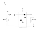
- FIG. 34 is a circuit diagram of a rechargeable battery according to a first example of the fourth embodiment.
- FIG. 35 is a circuit diagram of a rechargeable battery according to a second example of the fourth embodiment.
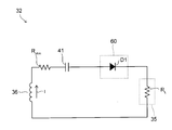
- FIG. 36 is a circuit diagram of a rechargeable battery according to a third example of the fourth embodiment.
- FIG. 37 is a schematic diagram illustrating a method for charging a rechargeable battery according to another embodiment.
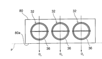
- FIG. 38 is a cross-sectional view of a battery pack according to another embodiment.
- the wireless charging method includes an electromagnetic induction method and a magnetic field resonance method.
- FIG. 1 is a schematic diagram of a charging system using an electromagnetic induction method.
- the charging system 1 includes a rechargeable battery 5 to be charged and a power transmission coil 2 for transmitting power to the rechargeable battery 5 wirelessly.
- An AC power supply 6 is connected to the power transmission coil 2, and a magnetic field H is generated around the power transmission coil 2 by a current supplied from the AC power supply 6 to the power transmission coil 2.
- the rechargeable battery 5 includes a battery body 4 and a power receiving coil 3 wound around the outer peripheral side surface thereof.
- An induced electromotive force is generated in the power receiving coil 3 by the magnetic field H, and the battery body 4 is charged by the induced electromotive force.
- the above-mentioned induced electromotive force is proportional to the number of turns of the receiving coil 3. For this reason, in this charging system 1, the power receiving coil 3 is wound around the outer peripheral side surface of the battery main body 4 without gaps, and the number of turns of the power receiving coil 3 is increased. It can be charged efficiently.
- the central axis C of the battery body 4 is tilted from the coil surface 2a of the power transmission coil 2, the interlinkage magnetic flux passing through the power reception coil 3 is reduced and the electromotive force of the power reception coil 3 is reduced. It is preferable to align the battery body 4 with the battery body 4 in advance.
- FIG. 2 is a schematic cross-sectional view of a jig used for such alignment.
- the jig 7 is used to charge a plurality of rechargeable batteries 5 at the same time by electromagnetic induction.
- the jig 7 incorporates the above-described power transmission coil 2 and accommodates the rechargeable batteries 5 inside.
- Housing 7a The bottom surface of the housing 7a is provided with a plurality of recesses 7b into which the rechargeable battery 5 standing vertically upward is fitted.
- the center axis C of the rechargeable battery 5 is oriented in the vertical direction by fitting the rechargeable battery 5 in the recess 7b, the center axis C is prevented from being inclined from the coil surface 2a, and the power receiving coil 3 is It can suppress that the interlinkage magnetic flux which penetrates can reduce.
- FIG. 3 is a schematic diagram of a charging system using a magnetic field resonance method.
- the charging system 10 includes a rechargeable battery 15 to be charged, and a power transmission coil 11 for transmitting power to the rechargeable battery 15 wirelessly.
- An AC power supply 12 and a resonance first capacitor 16 are connected to the power transmission coil 11, and a magnetic field H is generated around the power transmission coil 11 by a current supplied from the AC power supply 12 to the power transmission coil 11.
- the rechargeable battery 15 has a battery main body 14 and a power receiving coil 13 wound around the outer peripheral side surface thereof.
- the battery body 14 has an electrolyte and an electrode (not shown) inside a metal cylinder, and is charged by an electromotive force generated in the receiving coil 13 by receiving the magnetic field H.
- FIG. 4 is a developed view of the power receiving coil 13.
- the power receiving coil 13 is developed in a substantially rectangular shape, and has a first end portion 13a and a second end portion 13b. Under actual use, the end portions 13 a and 13 b are connected to the positive electrode and the negative electrode of the battery body 14, so that the induced electromotive force generated in the power receiving coil 13 can be supplied to the battery body 14.
- the power receiving coil 13 is also provided with a second capacitor 17 for resonance.
- the magnetic field resonance method relaxes the alignment of the coils 11 and 13 by increasing the Q value of the power receiving coil 13, but it is known that the Q value is given by the following equation (1). As the resistance R ohm of the power receiving coil 13 increases, the Q value decreases.
- Equation (1) ⁇ is the angular frequency of the current flowing through the power receiving coil 13, and L is the inductance of the power receiving coil 13.
- R rad is a radiation resistance representing the electromagnetic wave radiated from the power receiving coil 13.
- the rectangular receiving coil 13 has a shorter coil length than the closely wound receiving coil 3 as shown in FIG. 1, its resistance R ohm is small, and the Q value can be increased by equation (1).
- the developed shape of the power receiving coil 13 is thus rectangular, so that the outer peripheral side surface of the battery body 14 is largely exposed from the power receiving coil 13 as shown in FIG. 3 and the interlinkage magnetic flux penetrates the inside of the power receiving coil 13. Can be increased.
- FIG. 5 is a side view of the rechargeable battery 15 as viewed from the bottom surface of the cylindrical battery body 14.
- the magnetic field H penetrating the inside of the power receiving coil 13 reaches the battery body 14.
- the battery body 14 has a metal cylinder, an eddy current is generated in the cylinder by the magnetic field H, and the energy of the magnetic field H is used to generate the eddy current.
- this method has an advantage of being able to charge the rechargeable battery 15 lying in a horizontal plane as shown in FIG. 3, energy transfer between the power transmission coil 11 and the power reception coil 13 is not efficient. There's a problem.
- FIG. 6 is a side view of the rechargeable battery 15 studied in order to solve this problem.
- a magnetic sheet 18 containing ferrite or a soft magnetic material is wound around the side surface of the battery body 14.
- the developed shape of the power receiving coil 13 is a rectangular shape as in FIG.
- the magnetic sheet 18 has the property of taking in the magnetic field H therein. Therefore, according to this structure, it is possible to prevent the magnetic field H from reaching the battery body 14, suppress the wasteful consumption of the energy of the magnetic field H to generate eddy currents on the surface of the battery body 14, and It is considered that the energy of H can be effectively utilized for the electromotive force of the power receiving coil 13.
- a part of the magnetic field H taken into the magnetic sheet 18 in this way leaks out above the battery body 14 and generates an induced current I 1 in the power receiving coil 13.
- the direction of the induced current I 1 is opposite to that of the induced current I 2 generated by the magnetic field H in the power receiving coil 13 below the battery body 14.
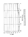
- the inventor of the present application simulated the relationship between the rolling angle ⁇ of the rechargeable battery 15 in the horizontal plane and the power transfer efficiency E.
- the rolling angle ⁇ is an angle between a direction D1 from the central axis C of the battery main body 14 toward the portion where the power receiving coil 13 is not present and a direction D2 of the magnetic field H in a side view, and the counterclockwise rotation about the central axis C.
- the direction of turning to the positive direction was taken as the positive direction.
- the efficiency E was defined as the ratio of the power of the AC power supply 12 and the power induced in the power receiving coil 13.
- an additional resistance that simulates the internal resistance of the rechargeable battery 15 is connected in series to the power receiving coil 13 and the load resistance is calculated for each of 0.1 ⁇ , 0.2 ⁇ , and 0.3 ⁇ .
- the efficiency E is less than 10% at almost all rolling angles ⁇ . Practically, it is preferable that the efficiency E is 50% or more. Therefore, it was found that the rechargeable battery 15 cannot withstand actual use.
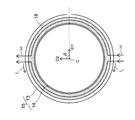
- FIG. 8 is a cross-sectional view of the rechargeable battery 15 studied in order to prevent the induced currents from canceling each other as described above.
- the receiving coil 13 having a rectangular developed shape as shown in FIG.
- the rolling angle ⁇ in this example is an angle between the direction D3 from the central axis C of the battery body 14 toward the end of the power receiving coil 13 and the direction D2 of the magnetic field H in a side view, and the central axis C is The direction that turns counterclockwise is defined as the positive direction.
- the power receiving coil 13 is not exposed to the magnetic field H leaking upward from the battery body 14, and the induced current is offset between the upper side and the lower side of the battery body 14. I can suppress it.
- FIG. 9 is a side view of the rechargeable battery 15 when the rolling angle ⁇ is 0 °.
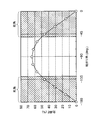
- FIG. 10 is a diagram obtained by simulating the relationship between the rolling angle ⁇ of the rechargeable battery 15 shown in FIGS. 8 and 9 and the power transfer efficiency E.
- FIG. 10 is a diagram obtained by simulating the relationship between the rolling angle ⁇ of the rechargeable battery 15 shown in FIGS. 8 and 9 and the power transfer efficiency E.
- the rolling angle ⁇ at which an efficiency E of 50% or more that can withstand practical use is obtained is limited to a range of ⁇ 40 ° centering on ⁇ 90 °, and the efficiency E that can withstand practical use is obtained in the remaining regions. Absent.
- the rolling angle ⁇ at which the efficiency E is less than 50% is referred to as a blind spot.
- the possibility that the rolling angle ⁇ enters the blind spot when the rechargeable battery 15 is laid in a horizontal plane increases, and the rechargeable battery 15 may not be sufficiently charged.
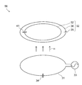
- FIG. 11 is a perspective view of a charging system using the magnetic field resonance method according to the present embodiment.
- the charging system 30 includes a power transmission coil 31 and a rechargeable battery 32.
- the power transmission coil 31 is wound around a first axis X1 oriented in the vertical direction, and generates a magnetic field H parallel to the first axis X1 by the current supplied from the AC power supply 33.
- a first capacitor 34 that forms an LC resonance circuit in cooperation with the power transmission coil 31 is provided between the power transmission coil 31 and the AC power supply 33.
- the power transmission coil 31 for example, a copper wire having good conductivity can be used.
- the rechargeable battery 32 has a cylindrical shape with the second axis X2 as a longitudinal direction and is exposed to the magnetic field H described above.
- the second axis X2 is not particularly limited, but in the following, the second axis X2 is provided in the horizontal plane, so that the cylindrical rechargeable battery 32 is placed in the horizontal plane.
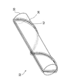
- FIG. 12 is a perspective view of the rechargeable battery 32.
- the rechargeable battery 32 includes a battery main body 35 and a power receiving coil 36.
- the battery body 35 includes a cylindrical outer peripheral side surface 35a, and a power receiving coil 36 is wound around the outer peripheral side surface 35a in a spiral shape.
- the power receiving coil 36 is, for example, a copper wire, and has a first end portion 36a and a second end portion 36b. And between the 1st end part 36a and the 2nd end part 36b, it extends along the longitudinal direction of the battery main body 35, and the linear conducting wire 40 which electrically connects each end part 36a, 36b. Is provided.
- the power receiving coil 36 according to the present embodiment is loosely wound around the battery main body 35, and the battery main body is between adjacent power receiving coils 36. There is a gap S in which 35 is greatly exposed.
- the power receiving coil 36 is represented by a continuous shape without interruption. However, in reality, the power receiving coil 36 is interrupted in the middle, and the power receiving coil 36 is electrically connected to the positive electrode and the negative electrode of the battery body 35 at the point of the interruption.
- the receiving coil 36 generates an electromotive force by being exposed to the magnetic field H, and the battery body 35 is charged by the electromotive force.
- FIG. 13 is a side view of the rechargeable battery 30 viewed from a direction parallel to the second axis X2 (see FIG. 10).
- the battery body 35 includes a metal cylindrical tube 38 and a magnetic sheet 39 surrounding the metal cylinder 38, and an outer peripheral side surface 35 a of the battery body 35 is defined by the surface of the magnetic sheet 39.
- the material of the magnetic sheet 39 is not particularly limited, but here, ferrite or soft magnetic material is used as the material of the magnetic sheet 39.
- the magnetic sheet 39 prevents the magnetic field H from reaching the cylindrical body 38 by taking the magnetic field H into itself. Thereby, generation
- FIG. 14 is a side view of the rechargeable battery 30.
- a second capacitor 41 that forms an LC resonance circuit in cooperation with the power receiving coil 36 is provided in the middle of the conducting wire 40.
- the battery body 35 is cylindrical, when the battery body 35 is rotated around the central axis C, a part of the power receiving coil 36 and the conductive wire 40 are hidden behind the battery body 35.
- the magnetic field H that penetrates the inside of the closed region R is provided as an interlinkage magnetic flux that penetrates the inside of the power receiving coil 36, and generates an induced current I in the power receiving coil 36.
- the magnetic field H passing outside the closed region R does not contribute to the interlinkage magnetic flux penetrating the power receiving coil 36, and therefore does not generate the induced current I in the power receiving coil 36.
- a closed region R through which the interlinkage magnetic flux penetrates is formed by spirally winding the power receiving coil 36 around the battery body 35, and the induced current I flows along the contour of the closed region R.
- the gap S in which the outer peripheral side surface 35a of the battery body 35 is exposed is provided by winding the power receiving coil 36 as sparsely as possible to increase the area of each closed region R when viewed from the side.
- the blind spot is defined as the rolling angle ⁇ at which the efficiency E of the power exchanged between the power transmission coil 31 and the power reception coil 36 is less than 50%.
- FIG. 15 is a side view for explaining the rolling angle ⁇ .
- the rolling angle ⁇ is an angle between the direction D4 from the central axis C toward the conductor 40 in the side view and the first axis X1 facing vertically upward, and the central axis C is counterclockwise.
- the direction of turning to the positive direction was taken as the positive direction.
- the inventor of the present application obtained the relationship between the rolling angle ⁇ and the efficiency E by simulation using the conditions shown in FIG.
- an additional resistance that simulates the internal resistance of the rechargeable battery 32 is connected in series to the power receiving coil 36, and the load resistance is calculated for each of 0.1 ⁇ , 0.2 ⁇ , and 0.3 ⁇ .
- the dead angle of the rolling angle ⁇ where the efficiency E is less than 50% is limited to the range of ⁇ 180 ° to 150 ° and ⁇ 30 ° to 0 °, and the angular region of the rolling angle ⁇ that does not become the dead angle. Reaches 120 °.
- FIG. 18 is a diagram showing a result obtained by performing the same simulation as in FIG. 17 for the comparative example using the power receiving coil 13 having a rectangular developed shape as shown in FIG.
- the diameter of the battery body 35 was 10 mm, and the diameter of the cross section of the power receiving coil 13 was 0.5 mm.
- the capacitance of the second capacitor 17 (see FIG. 4) connected to the power receiving coil 13 was 3470 pF.
- the range of angles that do not become blind spots is limited to 80 °, and the range that becomes blind spots becomes wider than in the present embodiment of FIG.
- the blind spot is thus reduced because the closed region R (see FIG. 14) in which the interlinkage magnetic flux penetrates the gap of the power receiving coil 36 when viewed from the side even when the battery body 35 is rotated around the central axis C. It is thought that it is formed.
- the blind spot is reduced, the possibility that the rolling angle ⁇ enters the blind spot when the user rolls the rechargeable battery 32 on the horizontal plane is reduced. Thereby, the positional relationship between the power transmission coil 31 and the power reception coil 13 for increasing the efficiency of power transfer from the power transmission coil 31 to the power reception coil 13 is relaxed, which can contribute to the convenience of the user.
- the number of turns of the power receiving coil 36 is not particularly limited. However, if the number of turns is large, the resistance R ohm of the power receiving coil 36 increases, so that the induced current I induced in the power receiving coil 36 is reduced. The efficiency E of power exchanged between the two decreases.
- the Q value decreases as the resistance R ohm of the power receiving coil 36 increases. Since the efficiency E is also reduced by a decrease in the Q value, in order to prevent the efficiency E from being decreased due to the decrease in the Q value, the number of turns of the power receiving coil 36 is reduced as much as possible to reduce the resistance R ohm . It is considered preferable to make it smaller.
- FIG. 19 is a graph obtained by investigating the relationship between the number of turns of the receiving coil 36 and the efficiency E by simulation.
- graphs A and B for the magnetic resonance type power receiving coil 36 graphs C and D for the electromagnetic induction type coil were also obtained for comparison.
- the second capacitor 41 (see FIG. 14) is provided in the magnetic resonance type power receiving coil 36. However, in this simulation, no capacitor is provided in the electromagnetic induction type coil.
- Graphs A and D are graphs obtained when the longitudinal direction of the battery body 35 is parallel to the coil surface of the power transmission coil 31.
- Graphs B and C are graphs obtained when the longitudinal direction of the battery body is perpendicular to the coil surface of the power transmission coil 31.
- the highest efficiency is obtained when the number of turns is 1.5.
- the efficiency decreases when the number of turns is less than 1.5. This is because when the number of turns is reduced, the resistance R ohm of the power receiving coil 36 is reduced as compared with the case where the number of turns is 1.5, but the total area of each closed region R is insufficient and the linkage flux is reduced. This is thought to be due to a decrease in efficiency E.
- the efficiency also decreases when the number of turns is more than 1.5. This is presumably because the Q value is lowered due to the increase in the resistance R ohm .
- the resistance R ohm of the power receiving coil 36 increases as the number of turns increases, and the efficiency E and Q value decrease as described above.
- FIG. 20A is a side view of the rechargeable battery 32 according to the present embodiment.
- the first pitch P1 for one turn of the power receiving coil 36 is larger than the second pitch P2 for a half turn of the power receiving coil 32.
- the angle between the induction current I f flowing through the power receiving coil 32 of the portions seen without hiding cell body 35, the induced current I b flowing through the power receiving coil 32 of the portion hidden behind the battery body 35 alpha Can be increased.
- the directions of the induced currents I f and I b are hardly anti-parallel to each other, so that the induced currents I f and I b can be prevented from canceling each other, and a large induced current is induced in the power receiving coil 32. Can do.
- FIG. 20B is a side view of the rechargeable battery 37 according to the comparative example.
- the power receiving coil 32 is spirally wound around the battery body 35 as in the present embodiment.
- the first pitch P1 for one turn of the power receiving coil 32 is set to be equal to or smaller than the second pitch P2 for a half turn of the power receiving coil 32.
- the first pitch P1 is larger than the second pitch P2.
- the aspect ratio is defined as L / R where L is the length in the longitudinal direction of the cylindrical battery body 35 and R is the diameter.
- the inventor of the present application investigated the relationship between the aspect ratio of each of the AAA to AAA batteries and the above-mentioned efficiency E.
- the survey results are shown in Table 1.
- the number of turns of the power receiving coil 36 was set to 1.5 in any of the batteries 1 to 4.
- AA to AAA batteries the ones with the highest market demand are AA batteries and AAA batteries. According to Table 1, the aspect ratios of both AA batteries and AAA batteries are 3.5 or more. Therefore, by winding the power receiving coil 36 around the battery body 35 having an aspect ratio of 3.5 or more, a rechargeable battery that is easily accepted by the market can be provided.
- the efficiency E is highest when the rolling angle ⁇ is ⁇ 90 °, and the efficiency is 0 when the rolling angle ⁇ is ⁇ 180 ° and 0 °. Obviously.
- FIG. 21A is a side view of the rechargeable battery 32 as viewed from the line-of-sight direction parallel to the magnetic field H when the rolling angle ⁇ is 0 °.
- the directions of the induced currents I1 to I3 in the portion flowing through the conductor 40 are not the same in all the closed regions R1 to R3, and the direction of the induced current I2 is different from the directions of the induced currents I1 and I3. Therefore, when the rolling angle ⁇ is 0 °, the currents I1 to I3 cancel each other and the efficiency becomes zero.
- the induced current I1 and the induced current I2 have different directions because the receiving coil 36 of the portion hidden behind the battery body 35 at the contact point A of the closed regions R1 and R2 through which the induced currents I1 and I2 flow. Is considered to be caused by the crossing of the conductor 40.
- FIG. 21B is a side view of the rechargeable battery 32 as viewed from the viewing direction parallel to the magnetic field H when the rolling angle ⁇ is ⁇ 90 °.
- the reason for the difference in efficiency depending on the rolling angle ⁇ is that the contact point A between the power receiving coil 36 and the conductor 40 hidden behind the battery body 35 may or may not appear depending on the direction of the line of sight. It is in.
- first direction D 0 the line-of-sight direction in which the contact point A does not appear as shown in FIG. 21B is referred to as a first direction D 0 .
- the efficiency E is maximized as follows.
- FIG. 22 is a cross-sectional view of the rechargeable battery 32 according to the first example of the present embodiment.
- the rechargeable battery 32 includes a case 45 that houses the battery main body 35 and the power receiving coil 36 described in the first embodiment.
- Case 45 is a cross-sectional shape is a polygon, and a flat surface 45a perpendicular to the first direction D 0.
- FIG. 23 is a cross-sectional view of the rechargeable battery 32 according to the second example of the present embodiment.
- the rechargeable battery 32 has a case 45 that houses the battery main body 35 and the power receiving coil 36 described in the first embodiment.
- the case 45 has a cylindrical shape and houses a plurality of weights 49 inside thereof.
- the way of arranging the weight 49 is not particularly limited.
- six weights 49 are arranged on the inner surface of the case 45 at every 60 ° angle about the central axis C of the battery body 35. At least one of the six weights 49, is positioned in the first direction D 0.
- the posture of the rechargeable battery 32 is stable with the first direction D 0 oriented vertically downward, and the rolling angle ⁇ is ⁇ 90 ° and the efficiency E is maximized without the user being aware of the rolling angle ⁇ .
- FIG. 24 is a cross-sectional view of the rechargeable battery 32 according to the third example of the present embodiment.
- a plurality of weights 49 are provided on the rechargeable battery 32 as in the second example of FIG.
- the sum of the moments of gravity acting on Kakutsumu 49 becomes 0 when facing the first direction D 0 vertically downward Like that.
- the posture of the rechargeable battery 32 is stabilized in a state where the first direction D 0 is directed vertically downward, and the efficiency E becomes the maximum value.
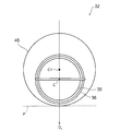
- FIG. 25 is a cross-sectional view of the rechargeable battery 32 according to the fourth example of the present embodiment.
- the rechargeable battery 32 has a cylindrical case 45 that houses the battery main body 35 and the power receiving coil 36 described in the first embodiment.
- the central axis C of the battery body 35 offset from the center axis C1 of the case 45 in a first direction D 0.
- the center of gravity of the rechargeable battery 32 is shifted in the first direction D 0 , when the rechargeable battery 32 is placed on the horizontal plane P, the posture of the rechargeable battery 32 is stabilized in a state where the first direction D 0 is directed vertically downward. It becomes like this. Therefore, even if the user is not aware of the rolling angle ⁇ , the rolling angle ⁇ is automatically ⁇ 90 °, and the efficiency E can be maximized.
- the rechargeable battery 32 has been described. However, these examples are applied to electronic devices such as smartphones, tablet PCs (Personal Computers), TV remote controllers, and home game machines as follows. It can also be applied.
- electronic devices such as smartphones, tablet PCs (Personal Computers), TV remote controllers, and home game machines as follows. It can also be applied.
- 26 to 29 are cross-sectional views of the electronic apparatus according to the present embodiment.
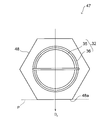
- FIG. 26 is a cross-sectional view of the electronic device 47 according to the first example of the present embodiment.
- the electronic device 47 includes a housing 48 that houses the rechargeable battery 32 of the first embodiment. Similar to the case 45 in FIG. 22, the casing 48 has a polygonal cross-sectional shape and includes a flat surface 48 a orthogonal to the first direction D 0 .
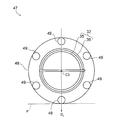
- FIG. 27 is a cross-sectional view of an electronic device 47 according to a second example of the present embodiment.
- the electronic apparatus 47 includes a cylindrical casing 48 that houses the rechargeable battery 32 of the first embodiment, and includes a plurality of weights 49 inside the casing 48.
- Each weight 49 is arranged in the same manner as in the example of FIG. 23, and the sum of the moments of gravity acting on each weight 49 when the center axis C3 of the cylindrical casing 48 is used as a reference is zero. Therefore, as described with reference to FIG. 23, the posture of the rechargeable battery 32 even in a state where the first direction D 0 is directed vertically downwards in the electronic apparatus 47 is stabilized. Therefore, even if the user is not aware of the rolling angle ⁇ of the rechargeable battery 32, the rolling angle ⁇ can be ⁇ 90 ° and the efficiency E can be maximized.
- FIG. 28 is a cross-sectional view of an electronic device 47 according to a third example of the present embodiment.
- a plurality of weights 49 are provided in a plurality of electronic devices 47 as in the second example of FIG.
- each weight 49 is the same as that described with reference to FIG. Therefore, in this case as well, since the sum of the moments of gravity acting on each weight 49 is 0, the rolling angle ⁇ is ⁇ 90 ° and the efficiency E is maximized without the user being aware of the rolling angle ⁇ . be able to.
- FIG. 29 is a cross-sectional view of an electronic device 47 according to a fourth example of this embodiment.
- This electronic device 47 has a cylindrical casing 48 that houses the rechargeable battery 32 of the first embodiment.
- the central axis C of the cell body 35 in the present embodiment offset from the center axis C3 of the housing 48 in a first direction D 0.
- the orientation of the rechargeable battery 32 is stabilized in a state where the angle direction D 0 is vertically downward, so that the rolling angle ⁇ is automatically set to ⁇ 90 °.
- the efficiency E can be maximized.
- a resonance coil is used together with the power transmission coil 31 and the power reception coil 36. According to the position where the resonance coil is provided, the present embodiment is roughly divided into the following first to third examples.
- FIG. 30 is a schematic diagram of the charging system according to the first example of the present embodiment.
- the first resonance coil 51 is provided in parallel with the power transmission coil 31, and the resonance first capacitor 34 is provided in the first resonance coil 51.
- the overall impedance of the charging system 55 varies as the internal resistance of the battery body 35 changes.
- the internal resistance of the battery main body 35 changes as a factor which changes the internal resistance of the battery main body 35.
- a temperature change of the battery main body 35 for example.
- an impedance matching device is provided in the power transmission coil 31 to prevent a change in impedance of the entire system.
- the width of the impedance that can be adjusted in the impedance matching unit is increased as compared with the case where there are only two coils, which can contribute to the convenience of the user.
- FIG. 31 is a schematic diagram of a charging system according to a second example of the present embodiment.
- FIG. 31 the same elements as those described in FIG. 30 are denoted by the same reference numerals as those in FIG. 30, and description thereof will be omitted below.
- the second resonance coil 52 is provided in parallel with the power receiving coil 36, and the second capacitor 41 is provided in the second resonance coil 52.
- FIG. 32 is a perspective view showing an example of how to wind the second resonance coil 36.
- the second resonant coil 52 is spirally wound around the battery body 35 in the same manner as the power receiving coil 36.
- FIG. 33 is a schematic diagram of a charging system according to a third example of the present embodiment.
- the charging system 57 is a combination of the first example and the second example, and uses the first resonance coil 51 and the second resonance coil 52 in combination. Use a coil.
- the range in which the impedance of the entire system can be adjusted can be further increased as compared with the first and second examples having three coils.
- the induced current is converted into direct current using a rectifier circuit as follows, and the rechargeable battery is charged with the direct current.
- FIG. 34 is a circuit diagram of the rechargeable battery 32 according to the first example of the present embodiment.
- the rechargeable battery 32 includes the battery main body 35, the power receiving coil 36, the second capacitor 41, and the rectifier circuit 60 described in the first embodiment.
- the resistance R ohm is the resistance of the power receiving coil 36
- the resistance R L is the internal resistance of the battery body 35.
- the rectifier circuit 60 is a full-wave rectifier circuit formed by bridge-connecting the first to fourth diodes D1 to D4, and has a function of limiting the induced current I flowing through the power receiving coil 36 in one direction.
- FIG. 35 is a circuit diagram of the rechargeable battery 32 according to the second example of the present embodiment.
- the second diode D2 and the fourth diode D4 are omitted from the rectifier circuit 60 in the first example (see FIG. 34), and the rectifier circuit 60 is a half-wave rectifier circuit.
- FIG. 36 is a circuit diagram of the rechargeable battery 32 according to the third example of the present embodiment.
- the first diode D1 is used as the rectifier circuit 60, and the direction in which the induced current I flows is limited to the forward direction of the first diode D1.
- the battery body 35 can be charged with the direct current.
- a diode is used for the rectifier circuit 60.
- rectifier circuit 60 according to the first to third examples may be used in combination with each of the first to third examples of the third embodiment.
- Table 2 is a table showing combinations of the number of coils on the battery body 35 side and the first to third examples of the present embodiment.
- the third example in which the number of coils on the battery main body 35 side is 2 and only one diode is applied is the viewpoint of reducing the cost of the rechargeable battery 32. To most preferred.
- the charging method of the rechargeable battery 32 is not limited to the first to fourth embodiments described above.
- FIG. 11 illustrates the case where one rechargeable battery 32 is charged by the magnetic field resonance method
- a plurality of rechargeable batteries 32 may be charged at a time as shown in FIG.
- the power transmission coil 31 is provided on the charging stand 70 parallel to the horizontal plane, and a plurality of rechargeable batteries 32 may be rolled on the charging stand 70. Since the blind spot of the rechargeable battery 32 is reduced as described above, even if a plurality of rechargeable batteries 32 are rolled in this manner, the possibility that the rolling angle of each rechargeable battery 32 enters the blind spot is reduced. It can be charged efficiently.
- the method of using the rechargeable battery 32 is not limited to the first to fourth embodiments described above.
- FIG. 38 is a cross-sectional view showing an example of how to use the rechargeable battery 32.
- a plurality of rechargeable batteries 32 are used as the battery pack 80.
- the cross-sectional shape of the battery pack 80 is, for example, a rectangular shape.
Landscapes
- Engineering & Computer Science (AREA)
- Power Engineering (AREA)
- General Chemical & Material Sciences (AREA)
- Chemical & Material Sciences (AREA)
- Chemical Kinetics & Catalysis (AREA)
- Electrochemistry (AREA)
- Computer Networks & Wireless Communication (AREA)
- Manufacturing & Machinery (AREA)
- Electromagnetism (AREA)
- Physics & Mathematics (AREA)
- Charge And Discharge Circuits For Batteries Or The Like (AREA)
- Secondary Cells (AREA)
- Battery Mounting, Suspending (AREA)
Abstract
Le but de l'invention est de relâcher la relation de position entre une bobine de réception de puissance et une bobine d'émission de puissance dans une batterie de charge, un système de charge et un dispositif électronique. Une batterie de charge possède : un corps principal de batterie (35), la surface latérale circonférentielle externe (35a) de celui-ci étant cylindrique ; et une bobine de réception de puissance (36) enroulée au plus une fois autour de la surface latérale circonférentielle externe (35a) et connectée électriquement au corps principal de batterie (35). Dans la batterie de charge, la bobine de réception de puissance (36) est enroulée autour de la surface latérale circonférentielle externe (35a) d'une manière hélicoïdale tout en donnant un espace pour présenter la surface latérale circonférentielle externe (35a).
Priority Applications (3)
| Application Number | Priority Date | Filing Date | Title |
|---|---|---|---|
| PCT/JP2013/063149 WO2014181462A1 (fr) | 2013-05-10 | 2013-05-10 | Batterie de charge, systeme de charge, et dispositif electronique |
| JP2015515729A JP6337889B2 (ja) | 2013-05-10 | 2013-05-10 | 充電池及び充電システム |
| US14/926,743 US10276900B2 (en) | 2013-05-10 | 2015-10-29 | Rechargeable battery, charging system, and electronic device |
Applications Claiming Priority (1)
| Application Number | Priority Date | Filing Date | Title |
|---|---|---|---|
| PCT/JP2013/063149 WO2014181462A1 (fr) | 2013-05-10 | 2013-05-10 | Batterie de charge, systeme de charge, et dispositif electronique |
Related Child Applications (1)
| Application Number | Title | Priority Date | Filing Date |
|---|---|---|---|
| US14/926,743 Continuation US10276900B2 (en) | 2013-05-10 | 2015-10-29 | Rechargeable battery, charging system, and electronic device |
Publications (1)
| Publication Number | Publication Date |
|---|---|
| WO2014181462A1 true WO2014181462A1 (fr) | 2014-11-13 |
Family
ID=51866963
Family Applications (1)
| Application Number | Title | Priority Date | Filing Date |
|---|---|---|---|
| PCT/JP2013/063149 Ceased WO2014181462A1 (fr) | 2013-05-10 | 2013-05-10 | Batterie de charge, systeme de charge, et dispositif electronique |
Country Status (3)
| Country | Link |
|---|---|
| US (1) | US10276900B2 (fr) |
| JP (1) | JP6337889B2 (fr) |
| WO (1) | WO2014181462A1 (fr) |
Cited By (3)
| Publication number | Priority date | Publication date | Assignee | Title |
|---|---|---|---|---|
| JP2022148257A (ja) * | 2021-03-24 | 2022-10-06 | 日油株式会社 | 起爆雷管用充電装置 |
| US12119670B2 (en) | 2019-03-18 | 2024-10-15 | Murata Manufacturing Co., Ltd. | Power reception device for wireless power supply system |
| US12126184B2 (en) | 2019-06-03 | 2024-10-22 | Murata Manufacturing Co., Ltd. | Power receiver for wireless power supply system and electronic device |
Families Citing this family (4)
| Publication number | Priority date | Publication date | Assignee | Title |
|---|---|---|---|---|
| US10516304B2 (en) * | 2015-12-22 | 2019-12-24 | Intel Corporation | Wireless charging coil placement for reduced field exposure |
| US10411492B2 (en) | 2015-12-23 | 2019-09-10 | Intel Corporation | Wireless power transmitter shield with capacitors |
| CN109314287B (zh) * | 2016-11-01 | 2022-05-27 | Tdk株式会社 | 便携式电子设备及无线电力传输装置 |
| DE102020205153A1 (de) * | 2020-04-23 | 2021-10-28 | Sivantos Pte. Ltd. | Batteriemodul und Hörvorrichtung |
Citations (3)
| Publication number | Priority date | Publication date | Assignee | Title |
|---|---|---|---|---|
| JP2005117748A (ja) * | 2003-10-06 | 2005-04-28 | Keisuke Goto | 非接触型再充電性電池及びその充電器 |
| JP2005124324A (ja) * | 2003-10-17 | 2005-05-12 | Kami Electronics Ind Co Ltd | 非接触式乾電池型充電器 |
| JP2013038967A (ja) * | 2011-08-09 | 2013-02-21 | Fdk Corp | 非接触充電対応型二次電池、非接触充電器 |
Family Cites Families (22)
| Publication number | Priority date | Publication date | Assignee | Title |
|---|---|---|---|---|
| US5212026A (en) * | 1991-10-04 | 1993-05-18 | Mitchell Danny E | Circular battery for flywheel |
| AU3046297A (en) * | 1997-06-16 | 1999-01-04 | Yehuda Binder | Battery substitute pack |
| GB0120697D0 (en) * | 2001-08-24 | 2001-10-17 | Coated Conductors Consultancy | Superconducting coil fabrication |
| GB2388716B (en) * | 2002-05-13 | 2004-10-20 | Splashpower Ltd | Improvements relating to contact-less power transfer |
| WO2004019352A1 (fr) * | 2002-08-26 | 2004-03-04 | Matsushita Electric Industrial Co., Ltd. | Element magnetique a utilisation multiphase et procede de production correspondant |
| US7456606B1 (en) * | 2008-04-23 | 2008-11-25 | International Business Machines Corporation | Battery label with wireless battery charging circuit |
| JP2010021388A (ja) * | 2008-07-11 | 2010-01-28 | Fujitsu Microelectronics Ltd | 半導体装置及びその製造方法 |
| JP4911148B2 (ja) * | 2008-09-02 | 2012-04-04 | ソニー株式会社 | 非接触給電装置 |
| JP5114364B2 (ja) * | 2008-11-04 | 2013-01-09 | 株式会社豊田自動織機 | 非接触電力伝送装置及びその設計方法 |
| WO2010077759A2 (fr) * | 2008-12-16 | 2010-07-08 | Eveready Battery Company, Inc. | Systèmes de batterie inductive et procédés de fonctionnement |
| JP2010193701A (ja) * | 2009-01-22 | 2010-09-02 | Sanyo Electric Co Ltd | 非接触式充電器 |
| JP2010183706A (ja) | 2009-02-04 | 2010-08-19 | Sanyo Electric Co Ltd | 充電台 |
| JP2010246219A (ja) * | 2009-04-03 | 2010-10-28 | Sanyo Electric Co Ltd | 二次電池収容装置 |
| JP2011045236A (ja) * | 2009-07-21 | 2011-03-03 | Sanyo Electric Co Ltd | 非接触式充電器 |
| JP5425571B2 (ja) * | 2009-09-14 | 2014-02-26 | 三洋電機株式会社 | 円柱状の電池ユニット |
| US8335572B2 (en) * | 2009-10-08 | 2012-12-18 | Cardiac Pacemakers, Inc. | Medical device lead including a flared conductive coil |
| US8460816B2 (en) * | 2009-10-08 | 2013-06-11 | Etymotic Research, Inc. | Rechargeable battery assemblies and methods of constructing rechargeable battery assemblies |
| JP2011142748A (ja) * | 2010-01-07 | 2011-07-21 | Sony Corp | ワイヤレス給電システム |
| US8744098B2 (en) * | 2010-02-04 | 2014-06-03 | Apple Inc. | Using an audio cable as an inductive charging coil |
| JP5640530B2 (ja) * | 2010-07-30 | 2014-12-17 | ソニー株式会社 | ワイヤレス給電システム |
| US9812730B2 (en) * | 2011-08-02 | 2017-11-07 | Johnson & Johnson Vision Care, Inc. | Biocompatible wire battery |
| JP5854687B2 (ja) * | 2011-08-03 | 2016-02-09 | 株式会社東芝 | 太陽光発電システム |
-
2013
- 2013-05-10 WO PCT/JP2013/063149 patent/WO2014181462A1/fr not_active Ceased
- 2013-05-10 JP JP2015515729A patent/JP6337889B2/ja not_active Expired - Fee Related
-
2015
- 2015-10-29 US US14/926,743 patent/US10276900B2/en active Active
Patent Citations (3)
| Publication number | Priority date | Publication date | Assignee | Title |
|---|---|---|---|---|
| JP2005117748A (ja) * | 2003-10-06 | 2005-04-28 | Keisuke Goto | 非接触型再充電性電池及びその充電器 |
| JP2005124324A (ja) * | 2003-10-17 | 2005-05-12 | Kami Electronics Ind Co Ltd | 非接触式乾電池型充電器 |
| JP2013038967A (ja) * | 2011-08-09 | 2013-02-21 | Fdk Corp | 非接触充電対応型二次電池、非接触充電器 |
Cited By (4)
| Publication number | Priority date | Publication date | Assignee | Title |
|---|---|---|---|---|
| US12119670B2 (en) | 2019-03-18 | 2024-10-15 | Murata Manufacturing Co., Ltd. | Power reception device for wireless power supply system |
| US12126184B2 (en) | 2019-06-03 | 2024-10-22 | Murata Manufacturing Co., Ltd. | Power receiver for wireless power supply system and electronic device |
| JP2022148257A (ja) * | 2021-03-24 | 2022-10-06 | 日油株式会社 | 起爆雷管用充電装置 |
| JP7608914B2 (ja) | 2021-03-24 | 2025-01-07 | 日油株式会社 | 起爆雷管用充電装置 |
Also Published As
| Publication number | Publication date |
|---|---|
| US20160049698A1 (en) | 2016-02-18 |
| JP6337889B2 (ja) | 2018-06-06 |
| JPWO2014181462A1 (ja) | 2017-02-23 |
| US10276900B2 (en) | 2019-04-30 |
Similar Documents
| Publication | Publication Date | Title |
|---|---|---|
| JP6337889B2 (ja) | 充電池及び充電システム | |
| US10340705B2 (en) | Wirelessly rechargeable battery and components thereof | |
| JP3226466U (ja) | コイルモジュールおよびそれを用いたワイヤレス電気エネルギー送信回路 | |
| CN103308948B (zh) | 检测装置、电力接收装置和电力发送装置 | |
| CN101699711B (zh) | 无接触式电能传输装置及方法 | |
| CN100550570C (zh) | 电能传输系统和在其中使用的初级装置 | |
| JP5490626B2 (ja) | 充電装置 | |
| US20170256990A1 (en) | Receiver Coil Arrangements for Inductive Wireless Power Transfer for Portable Devices | |
| US20130257367A1 (en) | Contactless charging system and charging device | |
| WO2020023284A1 (fr) | Dispositifs de transmission d'énergie sans fil | |
| JP2008301645A (ja) | 非接触式受電装置及びこれを具えた電子機器 | |
| JP5168438B2 (ja) | 電力伝送システム、及び受電ジャケット | |
| JP5952091B2 (ja) | ワイヤレス給電装置、ワイヤレス受電装置、ワイヤレス給電システム、および電機機器 | |
| CN107370249A (zh) | 电力发送装置以及非接触电力提供系统 | |
| JPWO2013111344A1 (ja) | 受電装置、電力伝送システム、及び電力伝送方法 | |
| US20180062441A1 (en) | Segmented and Longitudinal Receiver Coil Arrangements for Wireless Power Transfer | |
| JP6370558B2 (ja) | コイルユニット及びそれを有する給電システム | |
| KR20150110166A (ko) | 무선 충전 장치 | |
| KR20170111308A (ko) | 3축 무선전력 수신기 및 그 제조방법 | |
| JP7272420B2 (ja) | ワイヤレス給電システムの受電装置 | |
| CN104578444B (zh) | 无接点供电机构以及无接点供电机构用二次线圈 | |
| WO2020039502A1 (fr) | Dispositif de réception d'énergie | |
| KR102102567B1 (ko) | 무선 충전식 전지 및 그 구성요소들 |
Legal Events
| Date | Code | Title | Description |
|---|---|---|---|
| 121 | Ep: the epo has been informed by wipo that ep was designated in this application |
Ref document number: 13883986 Country of ref document: EP Kind code of ref document: A1 |
|
| ENP | Entry into the national phase |
Ref document number: 2015515729 Country of ref document: JP Kind code of ref document: A |
|
| NENP | Non-entry into the national phase |
Ref country code: DE |
|
| 122 | Ep: pct application non-entry in european phase |
Ref document number: 13883986 Country of ref document: EP Kind code of ref document: A1 |