WO2014181568A1 - Paire de lentilles de contact, lentille de contact et moyen de stockage - Google Patents
Paire de lentilles de contact, lentille de contact et moyen de stockage Download PDFInfo
- Publication number
- WO2014181568A1 WO2014181568A1 PCT/JP2014/054575 JP2014054575W WO2014181568A1 WO 2014181568 A1 WO2014181568 A1 WO 2014181568A1 JP 2014054575 W JP2014054575 W JP 2014054575W WO 2014181568 A1 WO2014181568 A1 WO 2014181568A1
- Authority
- WO
- WIPO (PCT)
- Prior art keywords
- unit
- contact lens
- lens
- pair
- function
- Prior art date
- Legal status (The legal status is an assumption and is not a legal conclusion. Google has not performed a legal analysis and makes no representation as to the accuracy of the status listed.)
- Ceased
Links
Images







Classifications
-
- G—PHYSICS
- G02—OPTICS
- G02C—SPECTACLES; SUNGLASSES OR GOGGLES INSOFAR AS THEY HAVE THE SAME FEATURES AS SPECTACLES; CONTACT LENSES
- G02C11/00—Non-optical adjuncts; Attachment thereof
- G02C11/10—Electronic devices other than hearing aids
-
- G—PHYSICS
- G02—OPTICS
- G02C—SPECTACLES; SUNGLASSES OR GOGGLES INSOFAR AS THEY HAVE THE SAME FEATURES AS SPECTACLES; CONTACT LENSES
- G02C7/00—Optical parts
- G02C7/02—Lenses; Lens systems ; Methods of designing lenses
- G02C7/04—Contact lenses for the eyes
Definitions
- the present disclosure relates to a pair of contact lenses, a contact lens, and a storage medium.
- contact lenses that are directly attached to the eyeball have been practically used as visual correction devices.
- the contact lens is also used to change the appearance of the eye. In this case, the lens is colored.
- Patent Document 1 discloses a system that simulates and presents an appearance when a user wears a color contact lens in order to reduce economical and material waste of a trial contact lens. .
- Patent Document 2 has been disclosed as an image display device using a contact lens.
- Patent Document 2 proposes a thinned image display device in which a display unit and a lens array unit are integrally provided on a curved surface, and are shaped like a contact lens that can be attached to the eye as a whole.
- Patent Documents 1 and 2 mentioned above there is no mention of a configuration in which a pair of contact lenses respectively attached to the eyes of both eyes operate in cooperation with each other.
- the present disclosure proposes a new and improved pair of contact lenses, contact lenses, and a storage medium in which the pair of contact lenses can operate in cooperation with each other.
- a pair of contact lenses including a second functional unit having a function different from the function of the first functional unit is proposed.
- a lens unit attached to an eyeball a functional unit provided in the lens unit, a communication unit provided in the lens unit and capable of communicating with an external device, and the communication unit from the external device.
- a contact lens is provided that includes a control unit that controls the function unit to operate in cooperation with the external device according to received information.
- a function unit provided in a lens unit attached to an eyeball a communication unit provided in the lens unit, capable of communicating with an external device, and received from the external device by the communication unit.
- a storage medium is proposed that stores a program for functioning as a control unit that controls the function unit to operate in cooperation with the external device.
- a pair of contact lenses can operate in cooperation with each other.
- FIG. 1 is a diagram for describing an outline of a pair of contact lenses 100 according to an embodiment of the present disclosure.
- the pair of contact lenses 100 is a pair of contact lenses including a contact lens 1R attached to the right eye 4R and a contact lens 1L attached to the left eye 4L.
- Each contact lens 1R, 1L is formed by a curved lens portion, and has a configuration that can be attached to and removed from the eyeball 4A so as to cover the iris 2 and the pupil 3 as a whole.
- the contact lenses 1 are also collectively referred to.
- the high-performance contact lens according to each embodiment of the present disclosure has been created by focusing on the above circumstances.
- the contact lens according to each embodiment of the present disclosure operates in cooperation with a contact lens having a different function attached to the other eye, thereby making the contact lens intelligent and greatly improving convenience. it can.
- FIG. 2 is a plan view illustrating an example of an external configuration of the contact lens 1 according to an embodiment of the present disclosure.
- the contact lens 1 according to the present embodiment is formed by a lens unit 10 attached to the eyeball.
- a circle 1 ⁇ / b> C has an inner area 1 ⁇ / b> A and an outer area 1 ⁇ / b> B. It is divided into and.
- the diameter D2 of the circle 1C is approximately equal to or greater than the maximum diameter D1 of the circle 2A inside the iris 2 of the human eye.
- a circuit unit 20 is provided in a region 1B outside the circle 1C.
- a smooth portion made of a transparent synthetic resin or the like is formed outside the circuit portion 20 (on the side facing the eyeball contact surface of the lens portion 10). Thereby, when the user wears the contact lens 1 on the eye, the user's eyelid can move smoothly.
- the circuit unit 20 includes a control unit 21, a wireless communication processing unit 22, an antenna 23, and a functional unit 30, as shown in FIG. Each configuration will be described below.
- the control unit 21 includes, for example, a microcomputer (microchip, IC chip) including a CPU (Central Processing Unit), a ROM (Read Only Memory), and a RAM (Random Access Memory), and controls each configuration of the circuit unit 20. To do.
- a microcomputer microchip, IC chip
- CPU Central Processing Unit
- ROM Read Only Memory
- RAM Random Access Memory
- the functional units 30 (first functional unit 30R and second functional unit 30L) having different functions provided in the pair of contact lenses 100 operate in cooperation with each other. Control to do.
- the antenna 23 is provided, for example, on the outer periphery of the region 1B of the lens unit 10 illustrated in FIG. 1 and wirelessly connects to another contact lens 1 (an example of an external device) attached to the other eye to transmit and receive data. Has the function to perform.
- the wireless communication processing unit 22 has a function of performing various signal processing on data transmitted and received by the antenna 23.
- the function unit 30 exhibits a predetermined function according to the control of the control unit 21.
- the function unit 30 includes, for example, an imaging function, a display function, various sensor functions (including a UI function), an illumination function, a sound collection function (may be used as an example of a UI function), a power supply function, and an external communication function. At least one.
- the arrangement of the function unit 30 illustrated in FIG. 2 is an example.
- the function unit 30 (display unit) having the display function is a circle of the lens unit 10. 1C is provided so as to cover the area 1A inside, and the display image is recognized by the wearer (user).
- the circuit unit 20 is provided in the region 1B as the outer periphery of the display unit 26 so as not to obstruct the image display by the display unit. Provided.
- the pair of contact lenses 100 (contact lenses 1R, 1L) according to the present embodiment includes functional units 30 (first functional unit 30R, second functional unit 30L) having different functions, and a wireless communication processing unit.
- the cooperative operation is performed via the antenna 22 and the antenna 23.
- each functional unit 30 having a different function is separately provided in the pair of contact lenses 100 (contact lenses 1R, 1L), so that the arrangement area can be saved as compared with the case where all the functional units 30 are provided in one contact lens 1. Space can be realized.
- Examples of such combinations of different functions include “imaging function and display / illumination / storage / battery / external communication / UI function”, “display function and illumination / storage / battery / external communication / UI function”, “ A combination of “memory function and battery / external communication / UI function” is conceivable. Further, a combination of subdivided imaging functions such as “special imaging (zoom / infrared / ultraviolet imaging) function and normal imaging” and “far-field imaging and near-field imaging” may be used. As described above, the different combinations of functions are various and are not particularly limited. Specific examples of the cooperative operation of different functions by the pair of contact lenses 100 of the present embodiment will be described in detail in “2. Each embodiment” that follows. To do.
- the configuration of the circuit unit 20 according to the present embodiment is not limited to the example illustrated in FIG. 1, and may further include a battery (power supply unit).
- the antenna 23 and the wireless communication processing unit 22 of the circuit unit 20 may have a function of receiving power. The power can be received from the figure.
- the wireless communication processing unit 22 and the antenna 23 according to the present embodiment are wirelessly connected to other contact lenses 1 mounted on the other eye and wirelessly connected to an external communication terminal (for example, a smartphone owned by the user). May be.
- the arrangement of the components of the circuit unit 20 shown in FIG. 1 is an example, and the circuit unit 20 according to the present embodiment may be arranged differently from FIG.
- FIG. 3 is a block diagram showing a configuration of the contact lens 1L-1 attached to the left eye 4L and the contact lens 1R-1 attached to the right eye 4R forming the pair of contact lenses 100 according to the first embodiment. It is.
- the contact lens 1L-1 includes a control unit 21L-1, a wireless communication processing unit 22, an antenna 23, and a functional unit 30L-1.
- the functional unit 30L-1 includes an imaging unit 24 and a sensor 27.
- the imaging unit 24 includes a lens system including an imaging lens, a diaphragm, a zoom lens, a focus lens, a drive system that causes the lens system to perform a focusing operation and a zoom operation, and imaging light obtained by the lens system. And a solid-state imaging device array that generates an imaging signal by photoelectric conversion.
- the solid-state imaging device array may be realized by, for example, a CCD (Charge Coupled Device) sensor array or a CMOS (Complementary Metal Oxide Semiconductor) sensor array.
- the imaging lens is provided so that the viewing direction of the user wearing the contact lens 1 is the imaging direction.
- the imaging unit 24 has an imaging signal processing unit that performs processing on a signal obtained by the solid-state imaging device and obtains an imaging signal as digital data.
- the imaging signal processing unit may perform blurring correction that corrects blurring of a captured image due to eyeball movement.
- the imaging unit 24 outputs the acquired captured image (digital data) to the control unit 21L-1.
- the sensor 27 is a variety of sensors for detecting external (peripheral) information of the contact lens 1, and is realized by, for example, a piezoelectric sensor (an example of a pressure sensor), an infrared sensor, an acceleration sensor, or the like.
- the sensor 27 according to the present embodiment is used to detect a camera start command, an image capture command, and a camera end command.
- the sensor 27 outputs the detection result to the control unit 21L-1.
- Control unit 21L-1 The control unit 21L-1 detects various commands based on the detection result of the sensor 27, and controls each configuration of the contact lens 1L-1 according to the detected various commands. Further, the control unit 21L-1 controls the contact lens 1L-1 and the contact lens 1R-1 to operate in cooperation. More specifically, for example, the control unit 21L-1 controls to display the captured image captured by the imaging unit 24 on the display unit 26 provided on the other contact lens 1R-1.
- the contact lens 1R-1 includes a control unit 21R-1, a wireless communication processing unit 22, an antenna 23, and a functional unit 30R-1.
- the functional unit 30R-1 includes a display unit 26.
- Display unit 26 A plurality of display elements (not shown) are arranged on the display unit 26.
- Each display element is configured by, for example, a liquid crystal display device, an organic EL (Electroluminescence) display device, a FED (Field Emission Display) display device, or the like.
- Each display element has a matrix on one curved surface (for example, a substantially spherical curved surface) corresponding to the surface of the human eye (or the eye of the animal when the contact lens 1 is attached to another animal). Arranged. Further, each display element has a display area, and each display element may display an independent image, or may display one image as a whole.
- the display area is arranged over the entire area 1A (see FIG. 1) in the circle 1C.
- the diameter D2 of the circle 1C is set to a value equal to or greater than the maximum diameter of the pupil (pupil) 3 (the maximum diameter of the circle 2A inside the iris 2) D1.
- the display area always exists over the entire pupil 3. Therefore, the light of the image in a larger display area is surely formed on the retina of the eyeball.
- the diameter D2 of the circle 1C is smaller than the diameter D3 of the circle 2B outside the iris 2, but may be larger.
- the display elements are densely arranged at a pitch that allows one person to recognize one image as a whole (so that the image is not locally lost).
- the display unit 26 transmits external light when the image is not displayed, the user can visually recognize the external image (real space scenery).
- Control unit 21R-1 controls the display unit 26 to display the captured image transmitted from the contact lens 1L-1 via the antenna 23 and the wireless communication processing unit 22.
- the configuration of the contact lens 1L-1 and the contact lens 1R-1 has been specifically described above. With the above configuration, the captured image captured by the contact lens 1L-1 attached to the left eye 4L can be displayed by the contact lens 1R-1 attached to the right eye 4R.
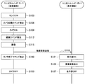
- FIG. 4 is a sequence diagram illustrating an example of cooperation processing according to the first embodiment.
- step S103 the sensor 27 of the contact lens 1L-1 is turned on. Specifically, for example, when the contact lens 1L-1 is supplied with power, or when a predetermined trigger signal is received from the outside (an external communication terminal such as a smartphone or a tablet terminal possessed by the user), Enters.
- the sensor 27 whose power is turned on outputs the detection result to the control unit 21L-1.
- step S106 the control unit 21L-1 detects a camera activation command based on the detection result by the sensor 27. Specifically, for example, when the opening / closing of the eyelid in contact with the contact lens 1L-1 is detected by a piezoelectric sensor (an example of the sensor 27), the control unit 21L-1 indicates that the eyelid is closed twice. It may be detected as a “command”.
- step S109 when the control unit 21L-1 detects a “camera activation command”, the imaging unit 24 is activated.
- step S112 the control unit 21L-1 detects an imaging command (shutter command) based on the detection result by the sensor 27. Specifically, for example, when a wrinkle that contacts the contact lens 1L-1 is consciously closed (for example, when the eyelid is closed for 0.5 seconds or more), the control unit 21L-1 detects it as an “imaging command”. .
- step S115 when the control unit 21L-1 detects the “imaging command”, the imaging unit 24 images the subject.
- step S118 the control unit 21L-1 transmits the captured image captured by the imaging unit 24 to the contact lens 1R-1 via the antenna 23 and the wireless communication processing unit 22.
- step S121 when the control unit 21R-1 of the contact lens 1R-1 receives the captured image from the contact lens 1L-1, the display unit 26 is turned on.
- step S124 the control unit 21R-1 controls to display the captured image received from the contact lens 1L-1 on the display unit 26.
- the control unit 21R-1 controls to display the captured image received from the contact lens 1L-1 on the display unit 26.
- the user can view the captured image captured with one contact lens 1L-1 with the other contact lens 1R-1.
- step S127 the control unit 21R-1 turns off the display unit 26.
- the timing of turning off the display unit 26 may be a timing when a predetermined time has elapsed after displaying the captured image, or may be a timing when a “display unit end command” is detected.
- the “display unit end command” may be transmitted from the contact lens 1L-1, or may be detected based on the detection result of the sensor 27 when the sensor 27 is provided in the contact lens 1R-1. .
- step S130 the control unit 21L-1 of the contact lens 1L-1 detects a “camera end command” based on the detection result by the sensor 27. Specifically, for example, when the eyelid in contact with the contact lens 1L-1 is intentionally closed three times, the control unit 21L-1 detects it as a “camera end command”.
- step S133 when detecting the “camera end command”, the control unit 21L-1 turns off the imaging unit 24.
- the paired contact lenses 100 can realize the cooperative operation of the imaging function and the display function.
- FIG. 5 is a block diagram showing a configuration of a contact lens 1R-2 attached to the right eye 4R according to the second embodiment.
- the pair of contact lenses 100 according to the present embodiment is formed by a contact lens 1L-2 attached to the left eye 4L and a contact lens 1R-2 attached to the right eye 4R. Since the configuration of the contact lens 1L-2 is the same as that of the contact lens 1L-1 shown in FIG. 3, the description thereof is omitted here.
- the contact lens 1R-2 includes a control unit 21R-2, a wireless communication processing unit 22, an antenna 23, and a functional unit 30R-2.
- the functional unit 30R-2 includes an illumination unit 28.
- the illumination unit 28 is provided in the region 1B of the lens unit 10 and includes a light emitting unit and a light emitting circuit that emits light from the light emitting unit.
- the illumination unit 28 performs a light emission operation according to the control of the control unit 21R-2. Since the light emitting unit is attached to illuminate the front in a state where the contact lens 1R-2 is mounted on the user's eyeball 4A, the illumination unit 28 is an imaging unit included in the contact lens 1L-2 It is possible to illuminate 24 imaging directions (similar to the user's viewing direction).
- Control unit 21R-2 controls ON / OFF of the illumination unit 28 according to a command transmitted from the contact lens 1L-2 via the antenna 23 and the wireless communication processing unit 22.
- the configuration of the contact lens 1R-2 has been specifically described above. With the above configuration, the contact lens 1R-2 attached to the right eye 4R can perform illumination control in cooperation with the contact lens 1L-2 attached to the left eye 4L.
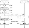
- FIG. 6 is a sequence diagram illustrating an example of cooperation processing according to the second embodiment.
- steps S143 to S152 shown in FIG. 6 is the same as the processing shown in steps S103 to S112 shown in FIG.
- step S155 when detecting the “imaging command” (shutter command), the control unit 21L-1 transmits an illumination ON command to the contact lens 1R-2 via the antenna 23 and the wireless communication processing unit 22. To do.
- step S158 when receiving the illumination ON command from the contact lens 1L-2, the control unit 21R-2 of the contact lens 1R-2 controls the illumination unit 28 to be turned on.
- step S161 the control unit 21L-2 of the contact lens 1L-2 images the subject with the imaging unit 24 in a state where the illumination unit 28 of the contact lens 1R-2 is turned on.
- the captured image captured by the imaging unit 24 may be stored in a memory area included in the control unit 21L-2, or may be stored in an external communication terminal (a smartphone owned by the user) via the antenna 23 and the wireless communication processing unit 22. Etc.).
- step S164 the control unit 21L-2 detects a “camera end command” based on the detection result of the sensor 27. Specifically, for example, when the eyelid in contact with the contact lens 1L-2 is intentionally closed three times, the control unit 21L-2 detects it as a “camera end command”.
- step S167 when detecting the “camera end command”, the control unit 21L-2 transmits an illumination OFF command to the contact lens 1R-2 via the antenna 23 and the wireless communication processing unit 22.
- step S170 the control unit 21R-2 of the contact lens 1R-2 controls the illumination unit 28 to be turned off in accordance with the illumination OFF command received from the contact lens 1L-2.
- step S173 when the control unit 21L-2 of the contact lens 1L-2 detects a “camera end command”, the imaging unit 24 is turned off.
- the paired contact lenses 100 can realize the cooperative operation of the imaging function and the illumination function.
- FIG. 7 is a block diagram showing a configuration of a contact lens 1L-3 attached to the left eye 4L and a contact lens 1R-3 attached to the right eye 4R forming the pair of contact lenses 100 according to the third embodiment. It is.
- the contact lens 1L-3 includes a control unit 21L-3, a wireless communication processing unit 22, an antenna 23, and a functional unit 30L-3.
- the functional unit 30L-3 includes a sensor 27.
- the control unit 21L-3 detects a camera start command, an imaging command, and a camera end command based on the detection result by the sensor 27, and sends each detected command to the contact lens via the antenna 23 and the wireless communication processing unit 22. Send to 1R-3.
- the contact lens 1L-3 has been specifically described above.
- the contact lens 1 ⁇ / b> L- 3 has a UI (user interface) function for accepting a user operation by the sensor 27.
- the contact lens 1R-3 includes a control unit 21R-3, a wireless communication processing unit 22, an antenna 23, and a functional unit 30R-3.
- the functional unit 30R-3 includes the imaging unit 24.
- the control unit 21R-3 controls the imaging operation by the imaging unit 24 in accordance with each command transmitted from the contact lens 1L-3.
- the configuration of the contact lens 1L-3 and the contact lens 1R-3 has been specifically described above.
- a user operation (each command) is detected by the contact lens 1L-3 attached to the left eye 4L, and the contact lens 1R-3 attached to the right eye 4R is detected according to the detected user operation.
- the imaging unit 24 included in is controlled.
- FIG. 8 is a sequence diagram illustrating an example of cooperation processing according to the third embodiment.
- steps S183 and S186 shown in FIG. 8 are the same as the processes shown in steps S103 and S106 shown in FIG. 4, description thereof is omitted here.
- step S189 when the control unit 21L-3 of the contact lens 1L-3 detects the “camera activation command” based on the detection result by the sensor 27, the camera activation command is transmitted to the antenna 23 and the wireless communication processing unit 22. Via the contact lens 1R-3.
- step S192 the control unit 21R-3 of the contact lens 1R-3 activates the imaging unit 24 in accordance with the camera activation command received from the contact lens 1L-3.
- step S195 the control unit 21L-3 of the contact lens 1L-3 detects an imaging command (shutter command) based on the detection result by the sensor 27.
- step S198 the control unit 21L-3 transmits an imaging command to the contact lens 1R-3 via the antenna 23 and the wireless communication processing unit 22.
- step S201 the control unit 21R-3 of the contact lens 1R-3 controls the imaging unit 24 to image the subject according to the imaging command received from the contact lens 1L-3.
- step S204 the control unit 21L-3 of the contact lens 1L-3 detects a “camera end command” based on the detection result by the sensor 27. Specifically, for example, when the eyelid in contact with the contact lens 1L-3 is intentionally closed three times, the control unit 21L-3 detects it as a “camera end command”.
- step S207 the control unit 21L-3 transmits a camera end command to the contact lens 1R-3 via the antenna 23 and the wireless communication processing unit 22.
- step S210 the control unit 21R-3 of the contact lens 1R-3 turns off the imaging unit 24 in accordance with the camera end command received from the contact lens 1L-3.
- the pair of contact lenses 100 can realize the cooperative operation of the UI function (operation input function) and the imaging function.
- the contact lens 1L-3 has a UI function for detecting a user operation (for example, blinking) by the sensor 27 (for example, a piezoelectric sensor), but the UI function according to the present embodiment is as follows. It is not limited to the method detected based on the detection result by the sensor 27. For example, each command (user operation) may be detected based on sound collected by a sound collection unit (microphone, hereinafter also referred to as a microphone).
- a sound collection unit microphone, hereinafter also referred to as a microphone.
- FIG. 9 is a block diagram showing a configuration of a contact lens 1L-4 attached to the left eye 4L according to the fourth embodiment.
- the pair of contact lenses 100 according to the present embodiment is formed by a contact lens 1L-4 attached to the left eye 4L and a contact lens 1R-4 attached to the right eye 4R. Since the configuration of the contact lens 1R-4 is the same as that of the contact lens 1R-3 shown in FIG. 7, the description thereof is omitted here.
- the contact lens 1L-4 includes a control unit 21L-4, a wireless communication processing unit 22, an antenna 23, and a functional unit 30L-4.
- the functional unit 30L-4 includes a microphone (sound collecting unit) 29.
- the microphone 29 is provided in the lens unit 10 and collects external sounds such as a user's voice and outputs the collected audio signals to the control unit 21L-4. Further, the waterproof function may be applied to the microphone 29 according to the present embodiment, or the microphone 29 may be realized by a structure capable of collecting underwater sound.
- Control unit 21L-4 detects a camera start command, an imaging command (shutter command), and a camera end command based on the audio signal collected by the microphone 29. In addition, the control unit 21L-4 controls each detected command to be transmitted to the contact lens 1R-4 via the antenna 23 and the wireless communication processing unit 22.
- the configuration of the contact lens 1L-4 has been specifically described above. With the above configuration, the contact lens 1L-4 attached to the left eye 4L detects a user operation (command) by voice, and the contact lens 1R- attached to the right eye 4R according to each detected command. 4 imaging operations can be controlled.
- FIG. 10 is a sequence diagram illustrating an example of cooperation processing according to the fourth embodiment.
- step S233 the microphone 29 of the contact lens 1L-4 is turned on. Specifically, for example, when power is supplied to the contact lens 1L-4, or when a predetermined trigger signal is received from the outside (an external communication terminal such as a smartphone or tablet terminal possessed by the user), the power supply of the microphone 29 Enters.
- the microphone 29 that is turned on picks up surrounding sounds and outputs the collected sound signals to the control unit 21L-4.
- step S236 the control unit 21L-4 analyzes the voice signal collected by the microphone 29 (voice recognition), and detects a camera activation command.
- step S239 when detecting the “camera activation command”, the control unit 21L-4 transmits the camera activation command to the contact lens 1R-4 via the antenna 23 and the wireless communication processing unit 22.
- step S242 the control unit 21R-4 of the contact lens 1R-4 activates the imaging unit 24 in accordance with the camera activation command received from the contact lens 1L-4.
- step S245 the control unit 21L-4 of the contact lens 1L-4 analyzes the audio signal collected by the microphone 29 and detects an imaging command (shutter command).
- step S248 the control unit 21L-4 transmits an imaging command to the contact lens 1R-4 via the antenna 23 and the wireless communication processing unit 22.
- step S251 the control unit 21R-4 of the contact lens 1R-4 controls the imaging unit 24 to image the subject according to the imaging command received from the contact lens 1L-4.
- step S254 the control unit 21L-4 of the contact lens 1L-4 analyzes the sound signal collected by the microphone 29 and detects a “camera end command”.
- step S257 the control unit 21L-4 transmits a camera end command to the contact lens 1R-4 via the antenna 23 and the wireless communication processing unit 22.
- step S260 the control unit 21R-4 of the contact lens 1R-4 turns off the imaging unit 24 in accordance with the camera end command received from the contact lens 1L-4.
- the pair of contact lenses 100 can realize the cooperative operation of the UI function and the imaging function by voice input.
- each contact lens 1R, 1L has a battery (power supply unit), or each contact lens 1R, 1L has an external power supply device. Is receiving power from
- each configuration of the pair of contact lenses 100 according to the present embodiment is not limited to this, and the battery is provided in one of the contact lenses 1R and 1L, and power is supplied to the other contact lens. An operation may be performed.
- the cooperative operation of such power supply will be described as a fifth embodiment with reference to FIG. 11 to FIG.
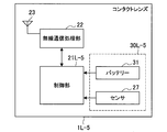
- FIG. 11 is a block diagram showing a configuration of a contact lens 1L-5 attached to the left eye 4L according to the fifth embodiment.
- the pair of contact lenses 100 according to the present embodiment is formed by the contact lens 1L-5 attached to the left eye 4L and having a battery function, and the contact lens 1R-5 attached to the right eye 4R and having an imaging function.
- the Since the configuration of the contact lens 1R-5 is the same as that of the contact lens 1R-3 shown in FIG. 7, the description thereof is omitted here.
- the contact lens 1L-5 includes a control unit 21L-5, a wireless communication processing unit 22, an antenna 23, and a functional unit 30L-5.
- the functional unit 30L-5 includes a sensor 27 and a battery 31.
- the battery 31 has a function of supplying power to each component of the contact lens 1L-5.
- the battery 31 may be realized by, for example, a solar power generation unit, or may be realized by an electric power reception processing unit that performs processing for receiving electric power from an external electric power supply device by the antenna 23.
- the control unit 21L-5 detects a camera start command, an imaging command, and a camera end command based on the detection result by the sensor 27, and sends the detected commands to the contact lens via the antenna 23 and the wireless communication processing unit 22. Send to 1R-5. Further, the control unit 21L-5 controls power transmission to the contact lens 1R-5 according to each detected command.
- the configuration of the contact lens 1L-5 has been specifically described above. With the above configuration, the contact lens 1L-5 attached to the left eye 4L controls power supply to the contact lens 1R-5 attached to the right eye 4R according to each detected command.
- FIG. 12 is a sequence diagram illustrating an example of cooperation processing according to the fifth embodiment.
- step S263 the sensor 27 of the contact lens 1L-5 is turned on.
- step S266 the control unit 21L-5 detects a camera activation command based on the detection result by the sensor 27. Specifically, for example, when the opening / closing of the eyelid in contact with the contact lens 1L-5 is detected by a piezoelectric sensor (an example of the sensor 27), the control unit 21L-5 indicates that the eyelid has been closed twice. It may be detected as a “command”.
- step S269 the control unit 21L-5 controls to transmit the power supplied from the battery 31 to the contact lens 1R-5.
- the power transmission can be realized by, for example, an electromagnetic induction method, a radio wave method, an electromagnetic resonance method, or the like. Further, power transmission to the contact lens 1R-5 is continuously performed thereafter.
- step S272 the control unit 21L-5 transmits a camera activation command to the contact lens 1R-5.
- steps S275 to S287 processing similar to that shown in steps S195 to S210 shown in FIG. 8 is performed. That is, an imaging command (shutter command) and a camera end command are detected in the contact lens 1L-5, and the imaging unit 24 of the contact lens 1R-5 is controlled according to each command. At this time, each component of the contact lens 1R-5 is driven by using electric power continuously transmitted from the contact lens 1L-5.
- step S290 the control unit 21R-5 of the contact lens 1R-5 notifies the contact lens 1L-5 that the imaging unit 24 is turned off.
- step S293 when the control unit 21L-5 of the contact lens 1L-5 receives that the imaging unit 24 is OFF, the control unit 21L-5 stops transmitting power to the contact lens 1R-5.
- the pair of contact lenses 100 can realize the cooperative operation of the battery function (power supply function) and the imaging function.
- the antenna 23 and the wireless communication processing unit 22 included in each contact lens 1R and 1L are used for at least the contact lenses 1R and 1L to communicate with each other. What is necessary is just to have a function.
- a function external communication function
- the external communication terminal is, for example, a communication terminal such as a smartphone, a mobile phone terminal, or a tablet terminal possessed by a user, a server on a network, or the like.
- a cooperative operation of such a communication function and another function for example, an imaging function
- FIG. 13 is a block diagram showing a configuration of a contact lens 1L-6 attached to the left eye 4L and a contact lens 1R-6 attached to the right eye 4R forming the pair of contact lenses 100 according to the sixth embodiment. It is.
- the contact lens 1L-6 includes a control unit 21L-6, a wireless communication processing unit 22, an antenna 23, and a functional unit 30L-6.
- the functional unit 30L-6 includes an external wireless communication processing unit 32 and an antenna 33.
- the antenna 33 is wirelessly connected to a communication terminal such as a smartphone, a mobile phone terminal, and a tablet terminal possessed by the user, and an external communication terminal such as a server on the network.
- the external wireless communication processing unit 32 processes wireless connection with the external communication terminal by the antenna 33.
- the contact lens 1L-6 may perform wireless communication with an external communication terminal via a human body instead of the antenna 33.
- the control unit 21L-6 controls to transmit the captured image received from the contact lens 1R-6 via the antenna 23 and the wireless communication processing unit 22 to the external communication terminal via the antenna 33 and the external wireless communication processing unit 32. To do.
- the contact lens 1R-6 includes a control unit 21R-6, a wireless communication processing unit 22, an antenna 23, and a functional unit 30R-6.
- the functional unit 30R-6 includes an imaging unit 24 and a sensor 27.
- the control unit 21R-6 controls the imaging operation by the imaging unit 24 according to the detection result by the sensor 27, and controls to transmit the captured image captured by the imaging unit 24 to the contact lens 1L-6.
- the configuration of the contact lens 1L-6 and the contact lens 1R-6 has been specifically described above. With the above configuration, the contact lens 1L-6 mounted on the left eye 4L transmits the captured image captured by the imaging unit 24 of the contact lens 1R-6 mounted on the right eye 4R to the external communication terminal. be able to.
- FIG. 14 is a sequence diagram illustrating an example of cooperation processing according to the sixth embodiment.
- steps S303 to S315 shown in FIG. 14 processing similar to the processing shown in steps S103 to S115 shown in FIG. 4 is performed. That is, in the contact lens 1R-6, a camera start command, an imaging command (shutter command), and a camera end command are detected based on the detection result by the sensor 27, and the imaging operation by the imaging unit 24 is controlled according to each command. Is done.
- step S318 the control unit 21R-6 of the contact lens 1R-6 transmits the captured image captured by the imaging unit 24 to the contact lens 1L-6 via the antenna 23 and the wireless communication processing unit 22.
- step S321 the control unit 21L-6 of the contact lens 1L-6 transmits the captured image received from the contact lens 1R-6 to the external communication terminal via the antenna 33 and the external wireless communication processing unit 32. Control as follows.
- step S324 the control unit 21R-6 of the contact lens 1R-6 detects a “camera end command” based on the detection result by the sensor 27. Specifically, for example, when the eyelid in contact with the contact lens 1R-6 is intentionally closed three times, the control unit 21R-6 detects it as a “camera end command”.
- step S327 when the control unit 21R-6 detects a “camera end command”, the imaging unit 24 is turned off.
- the paired contact lenses 100 can realize the cooperative operation of the external communication function and the imaging function.
- the cooperative operation according to the present embodiment is not limited to the external communication function and the imaging function, and may be, for example, an external communication function and a display function.
- one contact lens 1L having an external communication function may receive an image from a predetermined server on the network, and the other contact lens 1R having a display function may display the received image.
- the cooperative operation according to the present embodiment may be an external communication function and a storage function.
- data may be received from an external communication terminal by one contact lens 1L having an external communication function, and data received by the other contact lens 1R having a storage function may be stored.
- the storage function can be realized by a storage unit that records and reproduces data on a predetermined recording medium.
- Various recording media such as a fixed memory such as a flash memory, are conceivable.
- the storage unit may be configured to perform recording and reproduction according to the recording medium employed.
- a computer program for causing hardware such as a CPU, ROM, and RAM incorporated in the circuit unit 20 of the contact lens 1 to perform the functions of the control unit 21 of the contact lens 1 described above.
- a computer-readable storage medium storing the computer program is also provided.
- the contact lens a soft contact lens and a hard contact lens having different lens characteristics and lens diameters are known, but the contact lens 1 according to the present embodiment is applied to any type. obtain.
- the transmission process of each command in each flowchart described above may be terminated with a command completion notification from the transmission destination.
- the “illumination ON command transmission process” shown in S155 of FIG. 6 ends when a command completion notification (illumination ON notification) is received from the contact lens 1R-2, and then the “imaging process” shown in S161 is performed. Is called. As a result, it is possible to avoid the imaging process being performed by the contact lens 1L-2 before the contact lens 1R-2 is illuminated.
- this technique can also take the following structures.
- the pair of contact lenses is the pair of contact lenses according to (1), further including a communication unit that enables communication between the pair of lens units.
- the first and second functional units are at least one of an imaging unit, an illumination unit, a display unit, a storage unit, a sensor, a sound collection unit, and a power supply unit.
- a pair of contact lenses according to claim 1. The pair of contact lenses according to any one of (1) to (4), wherein the pair of contact lenses further includes a control unit that controls the first and second functional units to operate in cooperation with each other. lens. (6) The pair of contact lenses according to (5), wherein the control unit is provided in each of the pair of lens units.
- a functional unit provided in a lens unit attached to the eyeball;
- a communication unit provided in the lens unit and capable of communicating with an external device;
- a control unit for controlling the function unit to operate in cooperation with the external device according to information received from the external device by the communication unit;
- a storage medium storing a program for functioning as a computer.
Landscapes
- Physics & Mathematics (AREA)
- Health & Medical Sciences (AREA)
- Ophthalmology & Optometry (AREA)
- General Health & Medical Sciences (AREA)
- General Physics & Mathematics (AREA)
- Optics & Photonics (AREA)
- Acoustics & Sound (AREA)
- Otolaryngology (AREA)
- Eyeglasses (AREA)
Abstract
Priority Applications (5)
| Application Number | Priority Date | Filing Date | Title |
|---|---|---|---|
| JP2015515800A JP6402711B2 (ja) | 2013-05-09 | 2014-02-25 | 一対のコンタクトレンズ |
| CN201480019662.1A CN105122121B (zh) | 2013-05-09 | 2014-02-25 | 成对的隐形眼镜、隐形眼镜和存储介质 |
| US14/781,130 US9810926B2 (en) | 2013-05-09 | 2014-02-25 | Pair of contact lenses, contact lens and storage medium |
| EP14795063.8A EP2995991B1 (fr) | 2013-05-09 | 2014-02-25 | Paire de lentilles de contact, lentille de contact et moyen de stockage |
| US15/785,482 US10495904B2 (en) | 2013-05-09 | 2017-10-17 | Pair of contact lenses, contact lens and storage medium |
Applications Claiming Priority (2)
| Application Number | Priority Date | Filing Date | Title |
|---|---|---|---|
| JP2013099383 | 2013-05-09 | ||
| JP2013-099383 | 2013-05-09 |
Related Child Applications (2)
| Application Number | Title | Priority Date | Filing Date |
|---|---|---|---|
| US14/781,130 A-371-Of-International US9810926B2 (en) | 2013-05-09 | 2014-02-25 | Pair of contact lenses, contact lens and storage medium |
| US15/785,482 Division US10495904B2 (en) | 2013-05-09 | 2017-10-17 | Pair of contact lenses, contact lens and storage medium |
Publications (1)
| Publication Number | Publication Date |
|---|---|
| WO2014181568A1 true WO2014181568A1 (fr) | 2014-11-13 |
Family
ID=51867054
Family Applications (1)
| Application Number | Title | Priority Date | Filing Date |
|---|---|---|---|
| PCT/JP2014/054575 Ceased WO2014181568A1 (fr) | 2013-05-09 | 2014-02-25 | Paire de lentilles de contact, lentille de contact et moyen de stockage |
Country Status (5)
| Country | Link |
|---|---|
| US (2) | US9810926B2 (fr) |
| EP (1) | EP2995991B1 (fr) |
| JP (3) | JP6402711B2 (fr) |
| CN (1) | CN105122121B (fr) |
| WO (1) | WO2014181568A1 (fr) |
Cited By (5)
| Publication number | Priority date | Publication date | Assignee | Title |
|---|---|---|---|---|
| JP2015062063A (ja) * | 2013-09-23 | 2015-04-02 | ジョンソン・アンド・ジョンソン・ビジョン・ケア・インコーポレイテッドJohnson & Johnson Vision Care, Inc. | 複数の外部デバイスとの無線通信が可能な眼用レンズシステム |
| JP2017219847A (ja) * | 2016-06-10 | 2017-12-14 | ジョンソン・アンド・ジョンソン・ビジョン・ケア・インコーポレイテッドJohnson & Johnson Vision Care, Inc. | 医学的監視機能を備えた電子眼用レンズ |
| WO2019069555A1 (fr) * | 2017-10-05 | 2019-04-11 | ソニー株式会社 | Lentille de contact et accessoire |
| WO2019124000A1 (fr) | 2017-12-22 | 2019-06-27 | ソニー株式会社 | Lentille de contact et système de communication |
| KR20200095481A (ko) | 2017-12-15 | 2020-08-10 | 소니 주식회사 | 콘택트 렌즈 및 통신 시스템 |
Families Citing this family (18)
| Publication number | Priority date | Publication date | Assignee | Title |
|---|---|---|---|---|
| US10456241B2 (en) | 2016-10-20 | 2019-10-29 | Elwha Llc | Switchable lens devices, systems, and related methods |
| US10353463B2 (en) * | 2016-03-16 | 2019-07-16 | RaayonNova LLC | Smart contact lens with eye driven control system and method |
| US10502979B2 (en) * | 2016-12-21 | 2019-12-10 | Johnson & Johnson Vision Care, Inc. | Impedance sensing circuits for ophthalmic devices |
| TWI662316B (zh) * | 2017-07-24 | 2019-06-11 | 麥塔優光學股份有限公司 | 智慧型隱形眼鏡及其透光本體 |
| CN107874901B (zh) * | 2017-10-26 | 2024-09-13 | 杨铭轲 | 角膜接触镜和眼内照明系统 |
| US11333902B2 (en) * | 2017-12-12 | 2022-05-17 | RaayonNova LLC | Smart contact lens with embedded display and image focusing system |
| US10673414B2 (en) * | 2018-02-05 | 2020-06-02 | Tectus Corporation | Adaptive tuning of a contact lens |
| US10963045B2 (en) | 2018-04-25 | 2021-03-30 | International Business Machines Corporation | Smart contact lens system with cognitive analysis and aid |
| US10895762B2 (en) | 2018-04-30 | 2021-01-19 | Tectus Corporation | Multi-coil field generation in an electronic contact lens system |
| US10838239B2 (en) | 2018-04-30 | 2020-11-17 | Tectus Corporation | Multi-coil field generation in an electronic contact lens system |
| US10790700B2 (en) | 2018-05-18 | 2020-09-29 | Tectus Corporation | Power generation necklaces with field shaping systems |
| US10712564B2 (en) * | 2018-07-13 | 2020-07-14 | Tectus Corporation | Advanced optical designs for eye-mounted imaging systems |
| US11137622B2 (en) | 2018-07-15 | 2021-10-05 | Tectus Corporation | Eye-mounted displays including embedded conductive coils |
| US10838232B2 (en) * | 2018-11-26 | 2020-11-17 | Tectus Corporation | Eye-mounted displays including embedded solenoids |
| US10644543B1 (en) | 2018-12-20 | 2020-05-05 | Tectus Corporation | Eye-mounted display system including a head wearable object |
| US10944290B2 (en) | 2019-08-02 | 2021-03-09 | Tectus Corporation | Headgear providing inductive coupling to a contact lens |
| DE102020210593A1 (de) | 2020-08-20 | 2022-02-24 | Robert Bosch Gesellschaft mit beschränkter Haftung | Kontaktlinse, Verfahren zur Detektion eines Körperschalls mithilfe einer Kontaktlinse, Verfahren zur Herstellung einer Kontaktlinse |
| US11687317B2 (en) * | 2020-09-25 | 2023-06-27 | International Business Machines Corporation | Wearable computing device audio interface |
Citations (4)
| Publication number | Priority date | Publication date | Assignee | Title |
|---|---|---|---|---|
| JP2003177449A (ja) * | 2001-07-30 | 2003-06-27 | Hewlett Packard Co <Hp> | 電子装置を制御するシステム及び方法 |
| JP2003195230A (ja) * | 2001-12-21 | 2003-07-09 | Nippon Telegr & Teleph Corp <Ntt> | コンタクトレンズ、コンタクトレンズの探査具及びこれらを用いた探索方法、並びにコンタクトレンズのデータ管理システム |
| JP2006292883A (ja) | 2005-04-07 | 2006-10-26 | Sony Corp | 画像表示装置および方法 |
| JP2010211210A (ja) | 2009-03-11 | 2010-09-24 | Johnson & Johnson Vision Care Inc | インタラクティブ方式コンタクトレンズシミュレーションシステム及び方法 |
Family Cites Families (9)
| Publication number | Priority date | Publication date | Assignee | Title |
|---|---|---|---|---|
| US6570386B2 (en) | 2001-07-30 | 2003-05-27 | Hewlett-Packard Development Company, L.P. | System and method for providing power to electrical devices |
| US20100010336A1 (en) * | 2002-02-07 | 2010-01-14 | Pettegrew Jay W | Method and system for diagnosis of neuropsychiatric disorders including attention deficit hyperactivity disorder (adhd), autism, and schizophrenia |
| WO2008109867A2 (fr) * | 2007-03-07 | 2008-09-12 | University Of Washington | Lentille de contact active |
| US8092013B2 (en) * | 2008-10-28 | 2012-01-10 | Johnson & Johnson Vision Care, Inc. | Apparatus and method for activation of components of an energized ophthalmic lens |
| EP2433176B8 (fr) * | 2009-05-17 | 2017-11-29 | Helmut Binder | Lentille présentant un pouvoir réfringent variable pour l' oeil de l'homme |
| US8628194B2 (en) | 2009-10-13 | 2014-01-14 | Anton Sabeta | Method and system for contact lens care and compliance |
| CN102804032B (zh) * | 2009-12-04 | 2015-09-09 | 派诺特公司 | 电控聚焦眼科装置 |
| CN202837690U (zh) * | 2012-09-21 | 2013-03-27 | 天津三星光电子有限公司 | 一种隐形眼镜 |
| US9050185B2 (en) * | 2013-02-28 | 2015-06-09 | Johnson & Johnson Vision Care, Inc. | Electronic ophthalmic lens with pupil convergence sensor |
-
2014
- 2014-02-25 EP EP14795063.8A patent/EP2995991B1/fr active Active
- 2014-02-25 CN CN201480019662.1A patent/CN105122121B/zh not_active Expired - Fee Related
- 2014-02-25 JP JP2015515800A patent/JP6402711B2/ja active Active
- 2014-02-25 WO PCT/JP2014/054575 patent/WO2014181568A1/fr not_active Ceased
- 2014-02-25 US US14/781,130 patent/US9810926B2/en active Active
-
2017
- 2017-10-17 US US15/785,482 patent/US10495904B2/en active Active
-
2018
- 2018-09-13 JP JP2018171101A patent/JP6773092B2/ja active Active
-
2020
- 2020-06-30 JP JP2020113271A patent/JP7020514B2/ja active Active
Patent Citations (4)
| Publication number | Priority date | Publication date | Assignee | Title |
|---|---|---|---|---|
| JP2003177449A (ja) * | 2001-07-30 | 2003-06-27 | Hewlett Packard Co <Hp> | 電子装置を制御するシステム及び方法 |
| JP2003195230A (ja) * | 2001-12-21 | 2003-07-09 | Nippon Telegr & Teleph Corp <Ntt> | コンタクトレンズ、コンタクトレンズの探査具及びこれらを用いた探索方法、並びにコンタクトレンズのデータ管理システム |
| JP2006292883A (ja) | 2005-04-07 | 2006-10-26 | Sony Corp | 画像表示装置および方法 |
| JP2010211210A (ja) | 2009-03-11 | 2010-09-24 | Johnson & Johnson Vision Care Inc | インタラクティブ方式コンタクトレンズシミュレーションシステム及び方法 |
Non-Patent Citations (1)
| Title |
|---|
| See also references of EP2995991A4 |
Cited By (12)
| Publication number | Priority date | Publication date | Assignee | Title |
|---|---|---|---|---|
| JP2015062063A (ja) * | 2013-09-23 | 2015-04-02 | ジョンソン・アンド・ジョンソン・ビジョン・ケア・インコーポレイテッドJohnson & Johnson Vision Care, Inc. | 複数の外部デバイスとの無線通信が可能な眼用レンズシステム |
| JP2017219847A (ja) * | 2016-06-10 | 2017-12-14 | ジョンソン・アンド・ジョンソン・ビジョン・ケア・インコーポレイテッドJohnson & Johnson Vision Care, Inc. | 医学的監視機能を備えた電子眼用レンズ |
| WO2019069555A1 (fr) * | 2017-10-05 | 2019-04-11 | ソニー株式会社 | Lentille de contact et accessoire |
| KR20200066609A (ko) | 2017-10-05 | 2020-06-10 | 소니 주식회사 | 콘택트 렌즈 및 액세서리 |
| JPWO2019069555A1 (ja) * | 2017-10-05 | 2020-11-05 | ソニー株式会社 | コンタクトレンズおよびアクセサリ |
| US11589817B2 (en) | 2017-10-05 | 2023-02-28 | Sony Corporation | Contact lens and accessory |
| JP7275036B2 (ja) | 2017-10-05 | 2023-05-17 | ソニーグループ株式会社 | コンタクトレンズおよびアクセサリ |
| KR20200095481A (ko) | 2017-12-15 | 2020-08-10 | 소니 주식회사 | 콘택트 렌즈 및 통신 시스템 |
| US11534065B2 (en) | 2017-12-15 | 2022-12-27 | Sony Corporation | Contact lens and communication system |
| WO2019124000A1 (fr) | 2017-12-22 | 2019-06-27 | ソニー株式会社 | Lentille de contact et système de communication |
| KR20200097254A (ko) | 2017-12-22 | 2020-08-18 | 소니 주식회사 | 콘택트 렌즈 및 통신 시스템 |
| US11520168B2 (en) | 2017-12-22 | 2022-12-06 | Sony Corporation | Contact lens and communication system |
Also Published As
| Publication number | Publication date |
|---|---|
| US20180039100A1 (en) | 2018-02-08 |
| CN105122121B (zh) | 2019-10-01 |
| JP2020173468A (ja) | 2020-10-22 |
| US9810926B2 (en) | 2017-11-07 |
| JP6402711B2 (ja) | 2018-10-10 |
| EP2995991A4 (fr) | 2017-01-11 |
| JP6773092B2 (ja) | 2020-10-21 |
| US20160062150A1 (en) | 2016-03-03 |
| JP2019032538A (ja) | 2019-02-28 |
| EP2995991A1 (fr) | 2016-03-16 |
| CN105122121A (zh) | 2015-12-02 |
| JPWO2014181568A1 (ja) | 2017-02-23 |
| JP7020514B2 (ja) | 2022-02-16 |
| EP2995991B1 (fr) | 2022-03-30 |
| US10495904B2 (en) | 2019-12-03 |
Similar Documents
| Publication | Publication Date | Title |
|---|---|---|
| JP7020514B2 (ja) | 一対のコンタクトレンズ | |
| US10962808B2 (en) | Contact lens with image pickup control | |
| US10955689B2 (en) | Contact lens and storage medium | |
| CN109582141B (zh) | 根据眼球焦点控制显示屏的方法和头戴电子设备 | |
| CN112799508B (zh) | 显示方法与装置、电子设备及存储介质 | |
| CN105187726B (zh) | 一种多功能移动图像处理装置、处理方法 | |
| RU2571179C2 (ru) | Электронная офтальмологическая линза с датчиком взгляда глаз | |
| RU2586238C2 (ru) | Электронная офтальмологическая линза с датчиком конвергенции зрачков | |
| CN108205374B (zh) | 一种视频眼镜的眼球追踪模组及其方法、视频眼镜 | |
| WO2017049922A1 (fr) | Appareil de collecte d'informations d'image, procédé de collecte d'image, et application associée | |
| CN113572956A (zh) | 一种对焦的方法及相关设备 | |
| US20170255823A1 (en) | Control system, information processing device, control method, and program | |
| CN204948210U (zh) | 一种图像信息采集装置 | |
| US9474131B2 (en) | Lighting device, lighting system and wearable device having image processor | |
| CN104020578A (zh) | 具有眼睑位置传感器的电子式眼科透镜 | |
| CN105141938A (zh) | 视线定位装置 | |
| JP2014170208A (ja) | 後ろ向きの瞳孔径センサを有する電子眼科用レンズ | |
| JP2016520210A (ja) | プロセッサ制御された眼用レンズのためのシステム及び方法 | |
| CN205017431U (zh) | 一种多功能移动图像处理装置 | |
| WO2022193989A1 (fr) | Procédé et appareil d'exploitation de dispositif électronique, et dispositif électronique | |
| JP2020077271A (ja) | 表示装置、学習装置、及び、表示装置の制御方法 | |
| JP2014033265A (ja) | 撮像装置、撮像方法およびプログラム | |
| US20240267494A1 (en) | Intraocular system that includes an implant with an image formation device | |
| CN103995589A (zh) | 一种数字化隐形眼镜 | |
| US20250247603A1 (en) | Electronic device, control method of electronic device, and non-transitory computer readable medium |
Legal Events
| Date | Code | Title | Description |
|---|---|---|---|
| 121 | Ep: the epo has been informed by wipo that ep was designated in this application |
Ref document number: 14795063 Country of ref document: EP Kind code of ref document: A1 |
|
| ENP | Entry into the national phase |
Ref document number: 2015515800 Country of ref document: JP Kind code of ref document: A |
|
| WWE | Wipo information: entry into national phase |
Ref document number: 2014795063 Country of ref document: EP |
|
| WWE | Wipo information: entry into national phase |
Ref document number: 14781130 Country of ref document: US |
|
| NENP | Non-entry into the national phase |
Ref country code: DE |