WO2014181669A1 - Système d'alimentation électrique sans contact - Google Patents
Système d'alimentation électrique sans contact Download PDFInfo
- Publication number
- WO2014181669A1 WO2014181669A1 PCT/JP2014/061149 JP2014061149W WO2014181669A1 WO 2014181669 A1 WO2014181669 A1 WO 2014181669A1 JP 2014061149 W JP2014061149 W JP 2014061149W WO 2014181669 A1 WO2014181669 A1 WO 2014181669A1
- Authority
- WO
- WIPO (PCT)
- Prior art keywords
- power
- coil
- bag body
- power feeding
- power supply
- Prior art date
- Legal status (The legal status is an assumption and is not a legal conclusion. Google has not performed a legal analysis and makes no representation as to the accuracy of the status listed.)
- Ceased
Links
Images










Classifications
-
- B—PERFORMING OPERATIONS; TRANSPORTING
- B60—VEHICLES IN GENERAL
- B60L—PROPULSION OF ELECTRICALLY-PROPELLED VEHICLES; SUPPLYING ELECTRIC POWER FOR AUXILIARY EQUIPMENT OF ELECTRICALLY-PROPELLED VEHICLES; ELECTRODYNAMIC BRAKE SYSTEMS FOR VEHICLES IN GENERAL; MAGNETIC SUSPENSION OR LEVITATION FOR VEHICLES; MONITORING OPERATING VARIABLES OF ELECTRICALLY-PROPELLED VEHICLES; ELECTRIC SAFETY DEVICES FOR ELECTRICALLY-PROPELLED VEHICLES
- B60L53/00—Methods of charging batteries, specially adapted for electric vehicles; Charging stations or on-board charging equipment therefor; Exchange of energy storage elements in electric vehicles
- B60L53/10—Methods of charging batteries, specially adapted for electric vehicles; Charging stations or on-board charging equipment therefor; Exchange of energy storage elements in electric vehicles characterised by the energy transfer between the charging station and the vehicle
- B60L53/12—Inductive energy transfer
- B60L53/124—Detection or removal of foreign bodies
-
- B—PERFORMING OPERATIONS; TRANSPORTING
- B60—VEHICLES IN GENERAL
- B60L—PROPULSION OF ELECTRICALLY-PROPELLED VEHICLES; SUPPLYING ELECTRIC POWER FOR AUXILIARY EQUIPMENT OF ELECTRICALLY-PROPELLED VEHICLES; ELECTRODYNAMIC BRAKE SYSTEMS FOR VEHICLES IN GENERAL; MAGNETIC SUSPENSION OR LEVITATION FOR VEHICLES; MONITORING OPERATING VARIABLES OF ELECTRICALLY-PROPELLED VEHICLES; ELECTRIC SAFETY DEVICES FOR ELECTRICALLY-PROPELLED VEHICLES
- B60L53/00—Methods of charging batteries, specially adapted for electric vehicles; Charging stations or on-board charging equipment therefor; Exchange of energy storage elements in electric vehicles
- B60L53/10—Methods of charging batteries, specially adapted for electric vehicles; Charging stations or on-board charging equipment therefor; Exchange of energy storage elements in electric vehicles characterised by the energy transfer between the charging station and the vehicle
- B60L53/12—Inductive energy transfer
- B60L53/126—Methods for pairing a vehicle and a charging station, e.g. establishing a one-to-one relation between a wireless power transmitter and a wireless power receiver
-
- B—PERFORMING OPERATIONS; TRANSPORTING
- B60—VEHICLES IN GENERAL
- B60L—PROPULSION OF ELECTRICALLY-PROPELLED VEHICLES; SUPPLYING ELECTRIC POWER FOR AUXILIARY EQUIPMENT OF ELECTRICALLY-PROPELLED VEHICLES; ELECTRODYNAMIC BRAKE SYSTEMS FOR VEHICLES IN GENERAL; MAGNETIC SUSPENSION OR LEVITATION FOR VEHICLES; MONITORING OPERATING VARIABLES OF ELECTRICALLY-PROPELLED VEHICLES; ELECTRIC SAFETY DEVICES FOR ELECTRICALLY-PROPELLED VEHICLES
- B60L53/00—Methods of charging batteries, specially adapted for electric vehicles; Charging stations or on-board charging equipment therefor; Exchange of energy storage elements in electric vehicles
- B60L53/30—Constructional details of charging stations
- B60L53/35—Means for automatic or assisted adjustment of the relative position of charging devices and vehicles
- B60L53/36—Means for automatic or assisted adjustment of the relative position of charging devices and vehicles by positioning the vehicle
-
- B—PERFORMING OPERATIONS; TRANSPORTING
- B60—VEHICLES IN GENERAL
- B60L—PROPULSION OF ELECTRICALLY-PROPELLED VEHICLES; SUPPLYING ELECTRIC POWER FOR AUXILIARY EQUIPMENT OF ELECTRICALLY-PROPELLED VEHICLES; ELECTRODYNAMIC BRAKE SYSTEMS FOR VEHICLES IN GENERAL; MAGNETIC SUSPENSION OR LEVITATION FOR VEHICLES; MONITORING OPERATING VARIABLES OF ELECTRICALLY-PROPELLED VEHICLES; ELECTRIC SAFETY DEVICES FOR ELECTRICALLY-PROPELLED VEHICLES
- B60L53/00—Methods of charging batteries, specially adapted for electric vehicles; Charging stations or on-board charging equipment therefor; Exchange of energy storage elements in electric vehicles
- B60L53/30—Constructional details of charging stations
- B60L53/35—Means for automatic or assisted adjustment of the relative position of charging devices and vehicles
- B60L53/38—Means for automatic or assisted adjustment of the relative position of charging devices and vehicles specially adapted for charging by inductive energy transfer
-
- H—ELECTRICITY
- H01—ELECTRIC ELEMENTS
- H01F—MAGNETS; INDUCTANCES; TRANSFORMERS; SELECTION OF MATERIALS FOR THEIR MAGNETIC PROPERTIES
- H01F38/00—Adaptations of transformers or inductances for specific applications or functions
- H01F38/14—Inductive couplings
-
- H—ELECTRICITY
- H02—GENERATION; CONVERSION OR DISTRIBUTION OF ELECTRIC POWER
- H02J—ELECTRIC POWER NETWORKS; CIRCUIT ARRANGEMENTS OR SYSTEMS FOR SUPPLYING OR DISTRIBUTING ELECTRIC POWER; SYSTEMS FOR STORING ELECTRIC ENERGY
- H02J50/00—Circuit arrangements or systems for wireless supply or distribution of electric power
- H02J50/10—Circuit arrangements or systems for wireless supply or distribution of electric power using inductive coupling
- H02J50/12—Circuit arrangements or systems for wireless supply or distribution of electric power using inductive coupling of the resonant type
-
- H—ELECTRICITY
- H02—GENERATION; CONVERSION OR DISTRIBUTION OF ELECTRIC POWER
- H02J—ELECTRIC POWER NETWORKS; CIRCUIT ARRANGEMENTS OR SYSTEMS FOR SUPPLYING OR DISTRIBUTING ELECTRIC POWER; SYSTEMS FOR STORING ELECTRIC ENERGY
- H02J50/00—Circuit arrangements or systems for wireless supply or distribution of electric power
- H02J50/50—Circuit arrangements or systems for wireless supply or distribution of electric power using additional energy repeaters between transmitting devices and receiving devices
-
- H—ELECTRICITY
- H02—GENERATION; CONVERSION OR DISTRIBUTION OF ELECTRIC POWER
- H02J—ELECTRIC POWER NETWORKS; CIRCUIT ARRANGEMENTS OR SYSTEMS FOR SUPPLYING OR DISTRIBUTING ELECTRIC POWER; SYSTEMS FOR STORING ELECTRIC ENERGY
- H02J50/00—Circuit arrangements or systems for wireless supply or distribution of electric power
- H02J50/60—Circuit arrangements or systems for wireless supply or distribution of electric power responsive to the presence of foreign objects, e.g. detection of living beings
-
- H—ELECTRICITY
- H02—GENERATION; CONVERSION OR DISTRIBUTION OF ELECTRIC POWER
- H02J—ELECTRIC POWER NETWORKS; CIRCUIT ARRANGEMENTS OR SYSTEMS FOR SUPPLYING OR DISTRIBUTING ELECTRIC POWER; SYSTEMS FOR STORING ELECTRIC ENERGY
- H02J50/00—Circuit arrangements or systems for wireless supply or distribution of electric power
- H02J50/70—Circuit arrangements or systems for wireless supply or distribution of electric power involving the reduction of electric, magnetic or electromagnetic leakage fields
-
- H—ELECTRICITY
- H02—GENERATION; CONVERSION OR DISTRIBUTION OF ELECTRIC POWER
- H02J—ELECTRIC POWER NETWORKS; CIRCUIT ARRANGEMENTS OR SYSTEMS FOR SUPPLYING OR DISTRIBUTING ELECTRIC POWER; SYSTEMS FOR STORING ELECTRIC ENERGY
- H02J50/00—Circuit arrangements or systems for wireless supply or distribution of electric power
- H02J50/90—Circuit arrangements or systems for wireless supply or distribution of electric power involving detection or optimisation of position, e.g. alignment
-
- B—PERFORMING OPERATIONS; TRANSPORTING
- B60—VEHICLES IN GENERAL
- B60L—PROPULSION OF ELECTRICALLY-PROPELLED VEHICLES; SUPPLYING ELECTRIC POWER FOR AUXILIARY EQUIPMENT OF ELECTRICALLY-PROPELLED VEHICLES; ELECTRODYNAMIC BRAKE SYSTEMS FOR VEHICLES IN GENERAL; MAGNETIC SUSPENSION OR LEVITATION FOR VEHICLES; MONITORING OPERATING VARIABLES OF ELECTRICALLY-PROPELLED VEHICLES; ELECTRIC SAFETY DEVICES FOR ELECTRICALLY-PROPELLED VEHICLES
- B60L2200/00—Type of vehicles
- B60L2200/32—Waterborne vessels
-
- B—PERFORMING OPERATIONS; TRANSPORTING
- B60—VEHICLES IN GENERAL
- B60M—POWER SUPPLY LINES, AND DEVICES ALONG RAILS, FOR ELECTRICALLY- PROPELLED VEHICLES
- B60M7/00—Power lines or rails specially adapted for electrically-propelled vehicles of special types, e.g. suspension tramway, ropeway, underground railway
- B60M7/003—Power lines or rails specially adapted for electrically-propelled vehicles of special types, e.g. suspension tramway, ropeway, underground railway for vehicles using stored power (e.g. charging stations)
-
- Y—GENERAL TAGGING OF NEW TECHNOLOGICAL DEVELOPMENTS; GENERAL TAGGING OF CROSS-SECTIONAL TECHNOLOGIES SPANNING OVER SEVERAL SECTIONS OF THE IPC; TECHNICAL SUBJECTS COVERED BY FORMER USPC CROSS-REFERENCE ART COLLECTIONS [XRACs] AND DIGESTS
- Y02—TECHNOLOGIES OR APPLICATIONS FOR MITIGATION OR ADAPTATION AGAINST CLIMATE CHANGE
- Y02T—CLIMATE CHANGE MITIGATION TECHNOLOGIES RELATED TO TRANSPORTATION
- Y02T10/00—Road transport of goods or passengers
- Y02T10/60—Other road transportation technologies with climate change mitigation effect
- Y02T10/70—Energy storage systems for electromobility, e.g. batteries
-
- Y—GENERAL TAGGING OF NEW TECHNOLOGICAL DEVELOPMENTS; GENERAL TAGGING OF CROSS-SECTIONAL TECHNOLOGIES SPANNING OVER SEVERAL SECTIONS OF THE IPC; TECHNICAL SUBJECTS COVERED BY FORMER USPC CROSS-REFERENCE ART COLLECTIONS [XRACs] AND DIGESTS
- Y02—TECHNOLOGIES OR APPLICATIONS FOR MITIGATION OR ADAPTATION AGAINST CLIMATE CHANGE
- Y02T—CLIMATE CHANGE MITIGATION TECHNOLOGIES RELATED TO TRANSPORTATION
- Y02T10/00—Road transport of goods or passengers
- Y02T10/60—Other road transportation technologies with climate change mitigation effect
- Y02T10/7072—Electromobility specific charging systems or methods for batteries, ultracapacitors, supercapacitors or double-layer capacitors
-
- Y—GENERAL TAGGING OF NEW TECHNOLOGICAL DEVELOPMENTS; GENERAL TAGGING OF CROSS-SECTIONAL TECHNOLOGIES SPANNING OVER SEVERAL SECTIONS OF THE IPC; TECHNICAL SUBJECTS COVERED BY FORMER USPC CROSS-REFERENCE ART COLLECTIONS [XRACs] AND DIGESTS
- Y02—TECHNOLOGIES OR APPLICATIONS FOR MITIGATION OR ADAPTATION AGAINST CLIMATE CHANGE
- Y02T—CLIMATE CHANGE MITIGATION TECHNOLOGIES RELATED TO TRANSPORTATION
- Y02T90/00—Enabling technologies or technologies with a potential or indirect contribution to GHG emissions mitigation
- Y02T90/10—Technologies relating to charging of electric vehicles
- Y02T90/12—Electric charging stations
-
- Y—GENERAL TAGGING OF NEW TECHNOLOGICAL DEVELOPMENTS; GENERAL TAGGING OF CROSS-SECTIONAL TECHNOLOGIES SPANNING OVER SEVERAL SECTIONS OF THE IPC; TECHNICAL SUBJECTS COVERED BY FORMER USPC CROSS-REFERENCE ART COLLECTIONS [XRACs] AND DIGESTS
- Y02—TECHNOLOGIES OR APPLICATIONS FOR MITIGATION OR ADAPTATION AGAINST CLIMATE CHANGE
- Y02T—CLIMATE CHANGE MITIGATION TECHNOLOGIES RELATED TO TRANSPORTATION
- Y02T90/00—Enabling technologies or technologies with a potential or indirect contribution to GHG emissions mitigation
- Y02T90/10—Technologies relating to charging of electric vehicles
- Y02T90/14—Plug-in electric vehicles
Definitions
- the present invention relates to a non-contact power feeding system.
- This application is filed in Japanese Patent Application No. 2013-100739 filed in Japan on May 10, 2013, Japanese Patent Application No. 2013-101699 filed in Japan on May 13, 2013, and in Japan on May 16, 2013. Claiming priority based on Japanese Patent Application No. 2013-104390 filed and Japanese Patent Application No. 2013-143684 filed in Japan on July 9, 2013, the contents of which are incorporated herein.
- a non-contact power feeding system that can perform power feeding from the power feeding side to the power receiving side in a non-contact manner without connecting the power feeding side and the power receiving side with a wiring (cable) has been used in various applications.
- a non-contact power supply system uses power for charging a battery mounted on a vehicle such as an electric vehicle (EV) or a hybrid vehicle (HV) or a consumer device such as a household appliance. It is used for the purpose of supplying (see, for example, Patent Document 1).
- a power feeding coil (primary coil) provided on the power feeding side
- a power receiving coil (secondary coil) provided on the power receiving side
- the relative positions of the power receiving coil and the power feeding coil provided in the vehicle are appropriately set according to the stop position of the vehicle. It is necessary to.
- Patent Literature 2 a relay device housed in a vertically movable housing portion is arranged between a power feeding coil and a power receiving coil, and the relay device is moved according to the relative position between the power feeding coil and the power receiving coil.
- Patent Document 2 also discloses a technique for providing a foreign matter removing operation unit that removes foreign matter in the vicinity of a power transmission path during power transmission and avoiding adverse effects during power transmission caused by foreign matter different from the power supply target. ing.
- Patent Document 3 discloses a power reception support device that can perform appropriate support regarding correction of the position of a vehicle when receiving power from a power feeding device.
- the power receiving support device adjusts the vehicle height when the power receiving efficiency specifying unit that specifies the power receiving efficiency of the power receiving unit at the current position of the vehicle and the power receiving efficiency specified by the power receiving efficiency specifying unit is less than a threshold value. It is determined whether or not the power receiving efficiency is equal to or higher than a threshold value, and when it is determined that the power receiving efficiency is equal to or higher than the threshold value, a support unit that performs support for adjusting the vehicle height is provided.
- Patent Document 4 discloses a vehicle resonance that can efficiently supply power from the power supply side to the power receiving side by using the vehicle height adjustment function when performing non-contact power supply to an electric vehicle having a vehicle height adjustment function.
- a type non-contact power feeding system is disclosed.
- the vehicle resonance type non-contact power feeding system includes a power feeding side facility including a high frequency power source and a primary side resonance coil, a power receiving facility including a secondary side resonance coil for receiving power from the primary side resonance coil, and a vehicle. And an electric vehicle equipped with a high adjustment device.
- the power receiving facility uses a rectifier that rectifies the power received by the secondary resonance coil, a secondary battery that is supplied with the power rectified by the rectifier, and a vehicle height adjustment device that is used when charging the secondary battery.
- a control device that performs impedance adjustment of a resonance system including a secondary resonance coil and a secondary resonance coil.
- Patent Document 5 is provided in a vehicle capable of receiving and storing electric power from an external power transmission unit in a non-contact manner by a power receiving unit, so that the driver can easily charge and perform charging.
- a parking assistance device that can reduce the feeling of complexity is disclosed.
- the parking assist device includes a vehicle control unit that controls the vehicle so that the power transmission unit and the power reception unit are aligned based on the power reception status of the power reception unit, and a height sensor that detects a change in the vehicle height of the vehicle.
- the vehicle control unit uses the relationship between the power reception status and the distance between the power transmission unit and the power reception unit, which is determined in advance according to the height sensor output, to perform alignment based on the height sensor output and the power reception status. Do.
- Patent Document 6 discloses a technique for filling a space between a power transmission unit and a power reception unit with a bag body and preventing foreign matter from entering the space. Furthermore, Patent Document 7 discloses a technique for detecting and eliminating foreign matter that has entered between a power transmission coil and a power reception coil.
- Japanese Unexamined Patent Publication No. 2010-87353 Japanese Unexamined Patent Publication No. 2013-21886 Japanese Unexamined Patent Publication No. 2010-233394 Japanese Unexamined Patent Publication No. 2012-34468 Japanese Patent No. 4,868,093 Japanese Unexamined Patent Publication No. 2012-196015 Japanese Unexamined Patent Publication No. 2013-59239
- the constants of the coils and capacitors forming the resonator are devised. It is necessary to increase the Q value.
- the distance in which electric power can be transmitted in a non-contact manner is about half of the coil diameter, and thus it is necessary to use a large coil in order to realize long distance transmission.
- the relay device in the power feeding using the relay device, there is an appropriate position of the relay device for efficient non-contact power feeding.
- the distance between the relay coil and the power receiving coil changes. If the device is buried and fixed in the ground, it is not possible to efficiently perform non-contact power feeding from the power feeding device to the power receiving device.
- the withstand voltage level of components used for a power supply or the like is limited, it is limited to the withstand voltage level of the components, and it becomes difficult to sufficiently increase the power supply voltage on the power transmission side. For this reason, when the transmission distance of electric power is long, it is difficult to transmit much electric power in a short time.
- the present invention has been made in view of the above circumstances, and an object thereof is to provide a non-contact power feeding system capable of realizing long-distance transmission of electric power without causing an increase in cost and size. It is another object of the present invention to provide a non-contact power feeding system that can perform non-contact power feeding more efficiently than in the past.
- the present invention reduces the price of the vehicle and simplifies the configuration by not providing a vehicle height adjustment mechanism by disposing the feeding coil and the receiving coil at an appropriate distance with high power transmission efficiency.
- An object of the present invention is to eliminate the possibility that the height sensor is soiled or broken by foreign matters such as sludge and stones without being provided with the height sensor.
- Another object of the present invention is to enable a large amount of power to be transmitted even when the distance between the power feeding coil and the power receiving coil is long by appropriately adjusting the impedance of the system in the non-contact power feeding system.
- a first aspect of the non-contact power feeding system of the present invention includes a power feeding coil disposed on the ground, and a power receiving coil that is disposed above the power feeding coil from the power feeding coil.
- the power supply coil is mounted, and a first bag body capable of adjusting a vertical position of the power supply coil by expanding or contracting, the power supply coil, and the first And a second bag that occupies a space between the power feeding coil and the power receiving coil by being inflated.
- the 2nd aspect which concerns on the non-contact electric power feeding system of this invention is a 1st aspect.
- the 3rd aspect which concerns on the non-contact electric power feeding system of this invention is a 2nd aspect.
- WHEREIN The quantity of the gas which the said air supply / exhaust apparatus supplies to the said 1st bag body, and exhausts from the said 1st bag body. By finely adjusting the amount of gas, the vertical position of the feeding coil is finely adjusted.
- the 4th aspect which concerns on the non-contact electric power feeding system of this invention is a 2nd or 3rd aspect.
- the said air supply / exhaust apparatus expands the said 1st bag body, it is with respect to the said 2nd bag body.
- the first bag body is started after the start of gas exhaust from the first bag body. 2.
- the power supply coil is in contact with the periphery of the first bag body to expand or contract.
- An auxiliary bag body capable of adjusting the position in the horizontal plane is provided.
- a storage mechanism is provided for causing the auxiliary bag body stored in the ground to appear on the ground.
- a seventh aspect of the non-contact power feeding system includes a power feeding device having a power feeding coil, a power receiving device having a power receiving coil, and a relay coil positioned between the power feeding coil and the power receiving coil.
- a non-contact power feeding system that performs non-contact power feeding from the power feeding coil to the power receiving coil via the relay coil, and supports the relay coil and expands or contracts the relay coil to the power feeding coil and the power feeding coil.
- a first bag body moved between the power receiving coil and a gas supply means for supplying gas to the first bag body is provided.
- the eighth aspect includes a second bag body that expands or contracts between the power supply coil and the power reception coil, and the gas supply unit includes: Gas is supplied to the second bag.
- the relay coil is expanded or contracted in a direction orthogonal to a direction connecting the power feeding coil and the power receiving coil.
- a third bag body to be moved is provided, and the gas supply means supplies gas to the third bag body.
- the inside of the first bag body is viewed from a direction connecting the power feeding coil and the power receiving coil.
- the gas supply means supplies gas separately to each divided region of the first bag body.
- An eleventh aspect of the non-contact power feeding system of the present invention includes a power feeding device having a power feeding coil and a power receiving device having a power receiving coil, and performs non-contact power feeding from the power feeding coil to the power receiving coil.
- a power feeding device having a power feeding coil and a power receiving device having a power receiving coil, and performs non-contact power feeding from the power feeding coil to the power receiving coil.
- a first bag body that supports the power supply coil and moves the power supply coil toward the power reception coil by expanding, and a power supply coil supported by the power supply coil and in contact with the power reception device.
- a power supply coil that supplies gas to the first bag body.
- the spacer contacts the power receiving coil of the power receiving device.
- the power receiving device is a vehicle
- the power receiving coil is provided on the bottom surface
- the spacer is a flat top surface.
- the power feeding coil and the first bag body are provided in a recess provided on the ground side where the vehicle can stop. Is provided.
- the fifteenth aspect further includes a movement restricting portion that is provided in the recess and restricts movement of the power feeding coil.
- the spacer is detachable from the power feeding coil.
- a non-contact power feeding coil provided on the ground and a power receiving coil that is mounted on a moving body and that is supplied with power non-contactly from the power feeding coil.
- the second bag body that is provided on the ground side or the moving body side and is inflated between the power supply coil and the power receiving coil during power supply, and the inside of the inflated second bag body, A magnetic body disposed in the middle of a magnetic path formed between the power feeding coil and the power receiving coil.
- the magnetic body is made of powder, and is disposed in the middle of the magnetic path when the second bag body is expanded. And a magnetic material container that can accommodate the magnetic material, and a magnetic material supply device that supplies the magnetic material to the magnetic material container.
- the nineteenth aspect includes recovery means for recovering the magnetic body accommodated in the magnetic body accommodating portion to the magnetic body supply device.
- the magnetic substance accommodating portion is formed of a magnetic substance accommodating bag body that is expanded and contracted together with the second bag body.
- the second bag body is inflated to occupy the space between the power feeding coil and the power receiving coil, and the first bag body is inflated to bring the power feeding coil close to the power receiving coil. Therefore, long-distance transmission of power can be realized without increasing the cost and size of the non-contact power feeding system.
- the first bag body is expanded or contracted by supplying gas, and the relay coil is moved between the power feeding coil and the power receiving coil. It becomes possible to do.
- the power feeding coil and the power receiving coil are connected to each other through the spacer to transfer power between them (hereinafter referred to as “transmission efficiency”). (They may be abbreviated in some cases) and can be arranged to face each other with a distance that increases.
- transmission efficiency the spacer to transfer power between them
- the height sensor since the height sensor is not provided, the height sensor is not soiled or damaged by foreign matter such as splashed mud or stone.
- the non-contact electric power feeding system of this invention is equipped with the magnetic body arrange
- This magnetic body is magnetized by being installed in the middle of the magnetic path, and produces a region having a lower magnetic permeability than air. This region reduces the magnetic resistance between the feeding coil and the receiving coil. Therefore, according to the present invention, by appropriately adjusting the impedance of the non-contact power feeding system, it is possible to transmit a large amount of power even when the distance between the power feeding coil and the power receiving coil is long. Become.
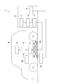
- FIG. 1 is a block diagram showing a configuration of a main part of the contactless power feeding system according to the first embodiment of the present invention.
- the non-contact power supply system 1 includes a power supply device 10, a power supply coil 20, an inner balloon 30a (first bag), an outer balloon 30b (second bag), and a power supply gas supply / exhaust device 40 ( A power supply / exhaust device) for supplying power to the vehicle M on which the battery 53 is mounted in a non-contact manner.
- the non-contact power supply system 1 is installed in, for example, a power supply station or a parking lot, and supplies power to the parked vehicle M without contact.
- the power supply device 10 includes a power source 11, a rectifier circuit 12, a power supply circuit 13, and a power supply control unit 14, generates electric power suitable for non-contact power supply to the vehicle M, and performs non-contact power supply to the vehicle M.
- Various controls necessary for the above are performed.
- the power supply device 10 is described as being installed on the ground. However, the power supply device 10 may be installed in the basement or may be installed above the vehicle M (for example, the ceiling). good.
- the output end of the power source 11 is connected to the input end of the rectifier circuit 12, and the power source 11 supplies the rectifier circuit 12 with AC power necessary for power feeding to the vehicle M.
- the power source 11 is a system power source that supplies three-phase AC power, such as 200 V or 400 V, or single-phase AC power of 100 V, for example.
- the input terminal of the rectifier circuit 12 is connected to the power supply 11 and the output terminal is connected to the power supply circuit 13.
- the rectifier circuit 12 rectifies and converts the AC power supplied from the power supply 11 into DC power.
- the direct current power is output to the power feeding circuit 13.
- the input end of the power supply circuit 13 is connected to the rectifier circuit 12 and the output end is connected to both ends of the power supply coil 20.
- the power supply circuit 13 converts the DC power from the rectifier circuit 12 into AC power and converts it. AC power is output to the feeding coil 20.
- the power supply circuit 13 includes a resonance capacitor that forms a power supply side resonance circuit together with the power supply coil 20. Under the control of the power supply control unit 14, the DC power from the rectifier circuit 12 is supplied to the power supply 11. The power is converted into AC power (high frequency power) having a frequency higher than that of AC power and output to the feeding coil 20.
- the power supply control unit 14 controls the power supply circuit 13 to generate power to be supplied to the vehicle M, and controls the power supply gas supply / exhaust device 40 to expand or contract the inner balloon 30a and the outer balloon 30b. .
- the power supply control unit 14 controls the power supply gas supply / exhaust device 40 to finely adjust the amount of gas supplied to the inner balloon 30a and the amount of gas exhausted from the inner balloon 30a. Then, the position of the feeding coil 20 in the vertical direction (vertical direction) is finely adjusted.
- the power supply control unit 14 includes a CPU (central processing unit), a memory, and the like, and performs the above-described various controls based on a power supply control program prepared in advance.
- As the gas for example, air can be used.
- the power supply coil 20 is a solenoid type coil, and supplies power to the vehicle M in a non-contact manner by generating a magnetic field corresponding to the high frequency power supplied from the power supply circuit 13. Both ends of the feeding coil 20 are connected to the output end of the feeding circuit 13, and the feeding coil 20 is coiled on the inner balloon 30a in an exposed state or molded with a nonmagnetic and nonconductive material such as plastic. It is mounted so that the shaft is substantially horizontal. When the coil type is a circular type, the coil axis is mounted so as to be substantially vertical.
- the inner balloon 30a is a kind of balloon in which a stretchable elastic material such as rubber is formed in a film shape, and is provided for adjusting the vertical position of the feeding coil 20.
- the inner balloon 30a is installed on the ground with the power supply coil 20 mounted on the center upper portion thereof, and is inflated or exhausted by gas supply or exhaust by the power supply gas supply / exhaust device 40. Shrink.
- the feeding coil 20 moves upward due to the expansion of the inner balloon 30a, and the feeding coil 20 moves downward due to the contraction of the inner balloon 30a.
- the planar view shape of the inner side balloon 30a is arbitrary, it is circular or a rectangular shape, for example.
- the outer balloon 30b is formed of a stretchable, non-magnetic and non-conductive elastic material such as rubber in the form of a film, and a central portion of the upper surface (a portion in contact with a power receiving coil 50 described later and a surrounding magnetic flux passing therethrough).
- This is a kind of balloon in which a powder made of a paramagnetic material such as aluminum powder or copper powder is attached to a portion other than a region where the efficiency of non-contact power feeding greatly decreases when affected.
- the central part of the upper surface has both magnetic permeability and expansion / contraction performance, and the remaining part where the paramagnetic powder is mixed and adhered has both the magnetic flux leakage reduction performance and expansion / contraction performance. ing.
- This outer balloon 30b prevents foreign matter from entering the space between the power feeding coil 20 and the power receiving coil 50 provided in the vehicle M, and is a part other than the end face (upper surface) of the power feeding coil 20 facing the power receiving coil 50 side. Provided in order to reduce the magnetic flux (leakage magnetic flux) radiated from.
- the outer balloon 30b is installed on the ground so as to cover (include) both the power supply coil 20 and the inner balloon 30a, and is inflated or exhausted by gas supply or exhaust by the power supply gas supply / exhaust device 40. Shrink. When the outer balloon 30b is inflated, the space between the power feeding coil 20 and the power receiving coil 50 is occupied by the outer balloon 30b. Note that the shape of the outer balloon 30b in plan view is arbitrary as in the case of the inner balloon 30a, but is, for example, circular or rectangular.
- the gas supply / exhaust device for power supply 40 supplies and exhausts gas to and from the inner balloon 30a and the outer balloon 30b under the control of the power supply control unit.
- This power supply gas supply / exhaust device 40 individually supplies gas to the inner balloon 30a, supplies gas to the outer balloon 30b, exhausts gas from the inner balloon 30a, and exhausts gas from the outer balloon 30b. It is possible. For this reason, one or both of the inner balloon 30a and the outer balloon 30b can be easily inflated or deflated.
- the power supply gas supply / exhaust device 40 includes a supply / exhaust pipe communicating with the inner balloon 30a and a supply / exhaust pipe communicating with the outer balloon 30b. In addition, gas is supplied to and exhausted from the outer balloon 30b.
- Vehicle M is an automobile that is driven by a driver and travels on a road, and is, for example, an electric car or a hybrid car that includes a travel motor as a power generation source. As shown in FIG. 1, the vehicle M includes a power receiving coil 50, a power receiving circuit 51, a charging circuit 52, a battery 53, and a power receiving control unit 54. Although omitted in FIG. 1, the vehicle M has a configuration necessary for traveling, such as an engine, the traveling motor, the operation handle, and a brake.
- the power receiving coil 50 is a solenoid-type coil, and is provided at the bottom of the vehicle M in a posture that enables non-contact power feeding with the power feeding coil 20 with high efficiency. Both ends of the power receiving coil 50 are connected to the input ends of the power receiving circuit 51, and the power receiving coil 50 generates an electromotive force by electromagnetic induction when the magnetic field of the power feeding coil 20 acts, and the generated electromotive force is sent to the power receiving circuit 51. Output.
- the sizes and shapes of the power feeding coil 20 and the power receiving coil 50 may be the same or different as long as highly efficient non-contact power feeding is possible.
- the input terminal of the power receiving circuit 51 is connected to both ends of the power receiving coil 50 and the output terminal is connected to the input terminal of the charging circuit 52.
- the power receiving circuit 51 converts the AC power supplied from the power receiving coil 50 into DC power.
- the converted DC power is output to the charging circuit 52.
- the power receiving circuit 51 includes a resonance capacitor that constitutes a power receiving resonance circuit together with the power receiving coil 50.
- the capacitance of the resonance capacitor of the power receiving circuit 51 is set so that the resonance frequency of the power receiving side resonance circuit is the same as the resonance frequency of the power feeding side resonance circuit described above.
- the input terminal of the charging circuit 52 is connected to the output terminal of the power receiving circuit 51 and the output terminal is connected to the input terminal of the battery 53.
- the charging circuit 52 uses the power (DC power) from the power receiving circuit 51 to the battery 53.
- the battery 53 is a rechargeable battery (for example, a secondary battery such as a lithium ion battery or a nickel metal hydride battery) mounted on the vehicle M, and supplies power to a travel motor (not shown).
- the power reception control unit 54 includes a CPU, a memory, and the like, and controls the charging circuit 52 based on a power reception control program prepared in advance.
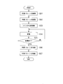
- FIG. 2 is a flowchart showing an example of the operation of the contactless power feeding system according to the first embodiment of the present invention
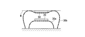
- FIGS. 3A to 3C are side sectional views for explaining the operation.
- operations of the vehicle M and the power supply apparatus 10 at the time of non-power supply will be briefly described, and then operations at the time of power supply in which the power supply apparatus 10 supplies power to the vehicle M in a non-contact manner will be described.
- the vehicle M When power is not supplied (for example, during normal operation of the vehicle M by the driver), the vehicle M is controlled by the power receiving control unit 54 to stop the charging circuit 52.
- the power supply device 10 stops the power supply circuit 13 and also includes the inner balloon 30a and the outer balloon 30b.
- the power supply control unit 14 performs control to exhaust the gas to the power supply gas supply / exhaust device 40 so that the gas is completely contracted.
- the installation position of the feeding coil 20 is grasped by the power receiving control unit 54.
- ascertaining from the output of position sensors such as a sound wave sensor not shown, or an optical sensor, is mentioned, for example.
- the position of the vehicle M is grasped by the power supply control unit 14 from the output of a position sensor such as a sound wave sensor or an optical sensor (not shown).
- a position sensor such as a sound wave sensor or an optical sensor (not shown).
- gas is first supplied to the power supply gas supply / exhaust device 40 until the outer balloon 30b is completely inflated.
- the control to be performed is performed by the power supply control unit 14 (step S11). That is, as shown in FIG. 3A, control is performed to completely inflate only the outer balloon 30b out of the inner balloon 30a and the outer balloon 30b in a completely deflated state.
- the inner balloon 30a is in a completely deflated state, but the outer balloon 30b is in a completely inflated state, and the gap between the feeding coil 20 and the receiving coil 50 is increased.
- the space is occupied by the fully inflated outer balloon 30b. That is, the outer balloon 30b covers the power receiving coil 50 so as to come into contact with the lower surface and the side surface of the power receiving coil 50 exposed from the bottom surface of the vehicle M by being inflated. This prevents foreign matter from entering the space between the power feeding coil 20 and the power receiving coil 50.
- the power supply control unit 14 performs control to supply gas from the power supply gas supply / exhaust device 40 to the inner balloon 30a to inflate the inner balloon 30a (step S12). That is, as shown in FIG. 3B, control is performed to inflate the inner balloon 30a in the fully deflated state contained in the outer balloon 30b in the completely inflated state. When the inner balloon 30a is inflated, the gas may be exhausted from the outer balloon 30b by the amount of gas supplied to the inner balloon 30a in accordance with the inflation of the inner balloon 30a.
- the inner balloon 30a is inflated in the outer balloon 30b, and the power supply coil 20 mounted on the inner balloon 30a moves upward. Accordingly, the feeding coil 20 is disposed in the vicinity of the power receiving coil 50 while preventing foreign matter from entering the space between the power feeding coil 20 and the power receiving coil 50 by the outer balloon 30b.
- step S13 the power supply gas supply / exhaust device 40 is controlled by the power supply control unit 14, and the position of the power supply coil 20 with respect to the power reception coil 50 is finely adjusted (step S13).
- the amount of gas supplied to the inner balloon 30 a and the amount of gas exhausted from the inner balloon 30 a are finely adjusted by the power supply gas supply / exhaust device 40 under the control of the power supply control unit 14.
- the position of the feeding coil 20 in the vertical direction is finely adjusted.
- the position of the power feeding coil 20 in the vertical direction is finely adjusted so that the amount of power supplied to the vehicle M is increased, for example. If it is not necessary to finely adjust the position of the feeding coil 20, step S13 may be omitted.
- the power supply circuit 13 of the power supply apparatus 10 is controlled by the power supply control unit 14 to start the power supply operation. Thereby, electric power is supplied from the power feeding coil 20 to the power receiving coil 50 of the vehicle M in a non-contact manner (step S14).
- the power reception control unit 54 controls the charging circuit 52 while monitoring the charging state of the battery 53 to charge the battery 53.
- the power receiving control unit 54 When the power receiving control unit 54 detects that the battery 53 is fully charged, the power receiving control unit 54 performs control to stop the charging circuit 52 and also displays an indicator (not shown) or the like (for example, charging the battery 53 provided in the driver's seat). Status indicator) is notified that the battery 53 is fully charged. With this notification, the driver can recognize that the battery 53 is fully charged.
- the power supply control unit 14 of the power supply apparatus 10 determines whether or not the power supply is completed while the noncontact power supply is being performed (step S15).
- the determination as to whether or not the power supply has ended can be made based on, for example, whether or not the amount of power supplied to the vehicle M has suddenly decreased.
- the power supply control unit 14 controls the power supply circuit 13 to continue the non-contact power supply (step). S14).
- the power supply control unit 14 controls the power supply circuit 13 to stop the power supply operation.
- the power supply control unit 14 When the power supply operation is stopped, the power supply control unit 14 performs control to exhaust the gas supplied to the inner balloon 30a to the power supply gas supply / exhaust device 40 and contract the inner balloon 30a (step S16). Subsequently, the power supply control unit 14 performs control to exhaust the gas supplied to the outer balloon 30b to the power supply gas supply / exhaust device 40 and contract the outer balloon 30b (step S17).
- the inner balloon 30a and the outer balloon 30b are deflated, the state shown in FIG. 3A is obtained, and the driver can drive the vehicle M and move from the place where the feeding coil 20 is installed.
- the inner balloon 30a and the outer balloon 30b are provided, and the outer balloon 30b is inflated to prevent foreign matter from entering the space between the power feeding coil 20 and the power receiving coil 50.
- the feeding coil 20 is brought close to the power receiving coil 50 by inflating the inner balloon 30a.
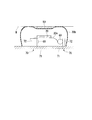
- FIG. 4 is a side sectional view showing a configuration of a main part of the non-contact power feeding system according to the second embodiment of the present invention.
- the whole structure of the non-contact electric power feeding system of this embodiment is as substantially the same as the non-contact electric power feeding system 1 shown in FIG.
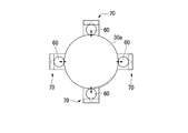
- the non-contact power feeding system of this embodiment includes a plurality of auxiliary balloons 60 (auxiliary bag bodies) and a plurality of storage mechanisms 70 inside the outer balloon 30 b (however, outside the inner balloon 30 a). This is an added configuration.
- FIGS. 5A to 5C are diagrams showing an auxiliary balloon and a storage mechanism in the second embodiment of the present invention.
- FIGS. 5A and 5B are plan views showing their arrangement, and FIG. 5C shows their appearance. It is a perspective view.
- the auxiliary balloon 60 and the accommodation mechanism 70 are arranged at equal intervals at three or four locations around the inner balloon 30a with the inner balloon 30a as the center.
- the three auxiliary balloons 60 are in contact with three different locations of the inner balloon 30a
- the four auxiliary balloons 60 are in four different locations of the inner balloon 30a. Each is in contact.
- the auxiliary balloon 60 is a kind of balloon in which a stretchable elastic material such as rubber is formed in a film like the inner balloon 30a described above, and is provided to adjust the position of the power feeding coil 20 in the horizontal plane. That is, when the auxiliary balloon 60 is inflated or contracted, the position of the abutting inner balloon 30a in the horizontal plane is adjusted, thereby adjusting the position of the feeding coil 20 mounted on the inner balloon 30a in the horizontal plane.
- a stretchable elastic material such as rubber
- the accommodating mechanism 70 accommodates the auxiliary balloon 60 in the ground, or causes the auxiliary balloon 60 accommodated in the ground to appear on the ground. Specifically, the accommodation mechanism 70 accommodates the auxiliary balloon 60 in the ground when the inner balloon 30a is deflated under the control of the power supply control unit 14, and when the inner balloon 30a is inflated. The auxiliary balloon 60 appears on the ground.
- the accommodation mechanism 70 includes an accommodation hole 71 and a flap 72.
- the accommodation hole 71 is a hole having a rectangular shape in plan view formed on the ground surface in order to accommodate the auxiliary balloon 60 in the ground.
- the flap 72 is a flat plate member having the same shape as the plan view of the accommodation hole 71 and is configured to be swingable around one end. The flap 72 is in a collapsed state when the auxiliary balloon 60 is housed in the ground, and is brought upright when the auxiliary balloon 60 appears on the ground. In addition, when the flap 72 is brought into a fallen state, the accommodation hole 71 is covered with the flap 72.
- An auxiliary balloon 60 is attached to one surface of the flap 72 (the surface facing the bottom surface of the receiving hole 71 when the flap 72 is in a collapsed state), and the air supply / exhaust air communicating with the auxiliary balloon 60 is provided inside the flap 72.
- a path 73 is formed.
- the air supply / exhaust path 73 is a flow path for gas supplied to the auxiliary balloon 60 and exhausted from the auxiliary balloon 60.
- the gas is supplied from, for example, a power supply gas supply / exhaust device 40 or exhausted toward the power supply gas supply / exhaust device 40.
- As the gas for example, air can be used.
- the contactless power feeding system according to the present embodiment also basically performs the operation according to the flowchart of FIG. That is, after the operation of inflating the outer balloon 30b (step S11), the operation of inflating the inner balloon 30a (step S12), and the operation of adjusting the position of the coil (step S13) are sequentially performed, non-contact power feeding is performed. Is performed (step S14).
- the flap 72 is in a collapsed state.
- the flap 72 is upright. Control to bring it into a state is performed.
- movement which adjusts the position of the coil of step S13 is performed, the operation
- the auxiliary balloon 60 when the auxiliary balloon 60 is inflated to bring each of the auxiliary balloons 60 into contact with the inner balloon 30a, and the auxiliary balloon 60 is inflated or deflated in this state, the force indicated by the arrows in FIGS. Acts on the balloon 30a. Then, the position of the inner balloon 30a in the horizontal plane is adjusted by the resultant force, and thereby the position of the feeding coil 20 in the horizontal plane is adjusted. The position of the inner balloon 30a in the horizontal plane is adjusted so that the amount of power supplied to the vehicle M is increased, for example.
- step S16 an operation for contracting the inner balloon 30a (step S16) and an operation for contracting the outer balloon 30b (step S17) are sequentially performed.
- the auxiliary balloon 60 is also deflated, and after the inner balloon 30a is deflated, an operation of accommodating the auxiliary balloon 60 in the accommodating hole 71 is performed with the flap 72 in a collapsed state.
- the inner balloon 30a and the outer balloon 30b are provided, and the outer balloon 30b is inflated to prevent entry of foreign matter into the space between the power feeding coil 20 and the power receiving coil 50.
- the power supply coil 20 is brought close to the power reception coil 50 by inflating the inner balloon 30a. For this reason, similarly to the first embodiment, it is possible to realize long-distance transmission of electric power without increasing the cost and size of the non-contact power feeding system, and leakage of leakage magnetic flux radiated from the power feeding coil 20 Can also be blocked.
- the auxiliary balloon 60 is provided to adjust the position of the inner balloon 30a (power feeding coil 20) in the horizontal plane. Therefore, even if the vehicle M parks and stops in a state where the power supply coil 20 and the power receiving coil 50 are displaced in the horizontal plane, the electric power can be transmitted efficiently.
- the present invention is not limited to the above embodiment, and can be freely changed within the scope of the present invention.
- the example in which the inner balloon 30a is inflated after the outer balloon 30b is inflated and the outer balloon 30b is deflated after the inner balloon 30a is deflated has been described.
- the method of inflating and contracting the inner balloon 30a and the outer balloon 30b is not limited to this, and any method can be used.
- the magnetic field resonance method is adopted as a method for contactless power feeding, but an electromagnetic induction method may be adopted.
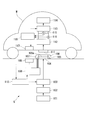
- the non-contact power feeding system includes a ground power feeding device S embedded in the ground and a vehicle M (power receiving device) that receives power from the ground power feeding device S.
- This non-contact power feeding system performs non-contact power feeding from the ground power feeding device S to the vehicle M based on a magnetic field resonance method which is one of the non-contact power feeding methods.
- the ground power supply device S is embedded in, for example, a stop position at an intersection or railroad crossing, or a parking / parking position of a parking lot, and performs non-contact power feeding to the vehicle M parked and parked at the parking / stopping position.
- the ground power supply device S includes a power source 101, a rectifier circuit 102, a power supply circuit 103, a power supply coil 104, a first bag body 105, a relay coil 106, a second bag body 107, and a gas supply / exhaust mechanism 108.
- the wireless communication unit 109 and the power supply control unit 110 are provided.
- the gas supply / exhaust mechanism 108 is a gas supply unit in the present embodiment.
- the power source 101 is an AC power source that supplies AC power necessary for power supply to the vehicle M to the rectifier circuit 102, and an output terminal of the power source 101 is connected to an input terminal of the rectifier circuit 102.
- the power source 101 is a system power source or a power generator that supplies three-phase AC power such as 200 V or 400 V or single-phase AC power of 100 V, for example.
- the input terminal of the rectifier circuit 102 is connected to the power supply 101, and the output terminal is connected to the power supply circuit 103.
- the rectifier circuit 102 rectifies AC power supplied from the power source 101 and converts it into DC power, and outputs the DC power to the power supply circuit 103.
- a DC power source such as a solar cell may be used as the power source 101, and the rectifier circuit 102 may be omitted (that is, DC power is supplied from the DC power source to the power feeding circuit 103).
- the power supply circuit 103 includes a power supply coil 104 and a resonance capacitor that forms a power supply side resonance circuit, and the DC power supplied from the rectifier circuit 102 based on a control command input from the power supply control unit 110 is supplied to the power supply 101.
- This is a type of inverter that converts AC power (high frequency power) having a frequency higher than that of AC power and supplies the power to the feeding coil 104.
- the feeding coil 104 is a circular coil or a solenoid coil, and in the case of a circular coil, the coil axis is in the vertical direction (vertical direction), and in the case of a solenoid coil, the coil axis is in the horizontal direction. And it is installed at the parking / stopping position in a state exposed on the ground surface or molded with a nonmagnetic and nonconductive material such as plastics, fiber reinforced plastics, ceramics or a composite material thereof. Both ends of the power supply coil 104 are connected to the output terminal of the power supply circuit 103.
- the feeding coil 104 feeds the vehicle M in a non-contact manner by generating a magnetic field when high-frequency power is supplied from the feeding circuit 103.
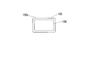
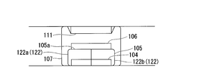
- the first bag 105 is a kind of balloon formed by forming a stretchable elastic material such as rubber into a film shape, and is installed on the ground in a state of including the power feeding coil 104. Moreover, the 1st bag body 105 is supporting the relay coil 106 by providing the relay coil 106 in contact with the one end surface (lower surface) on the upper side 105a (refer FIG.6 and FIG.7 A, 7B).
- the first bag body 105 is hermetically sealed. When gas (for example, air) is supplied from the gas supply / exhaust mechanism 108, the first bag body 105 expands and lifts the relay coil 106 upward, whereby the relay coil 106 will be described later. It moves toward the power receiving coil 111 of the vehicle M.
- gas for example, air
- the first bag body 105 is a kind in which a powder made of a paramagnetic flux shielding material such as aluminum powder or copper powder is attached to a portion other than the central portion of the upper surface (the portion facing the power receiving coil 111 described later).
- the central portion of the upper surface has both transmission performance against magnetic flux and expansion / contraction performance, and the remaining portion where the powder made of magnetic flux shielding material is mixed and adhered has both shielding performance against magnetic flux and expansion / contraction performance.
- the relay coil 106 includes a circular type coil or a solenoid type coil.
- the posture is such that the coil axis is in the vertical direction (vertical direction), and in the case of a solenoid type coil, the posture is such that the coil axis is in the horizontal direction.
- the first bag body 105 in an exposed state or in a state molded with a nonmagnetic and nonconductive material such as plastics, fiber reinforced plastics, ceramics, or a composite material thereof (see FIGS. 6 and 6). (See FIGS. 7A and 7B).
- the relay coil 106 includes a resonance circuit including a resonance capacitor and a resonance coil (the circular type coil or the solenoid type coil), and performs non-contact power supply from the power supply coil 104 to the power reception coil 111 of the vehicle M described later. Relay. Note that the resonance frequency of the resonance circuit of the relay coil 106 is set to be the same as the resonance frequency of the power feeding side resonance circuit.
- the second bag body 107 is a kind of balloon in which a stretchable elastic material such as rubber is formed into a film shape, and is installed on the ground in a state including the first bag body 105 and the relay coil 106.
- the second bag body 107 is sealed, and expands around the first bag body 105 and the relay coil 106 when gas (for example, air) is supplied from the gas supply / exhaust mechanism 108 (see FIG. 7A).
- the second bag body 107 is a kind in which a powder made of a paramagnetic flux shielding material such as aluminum powder or copper powder is attached to a portion other than the central portion of the upper surface (the portion facing the power receiving coil 111 described later).
- the central portion of the upper surface has both transmission performance against magnetic flux and expansion / contraction performance, and the remaining portion where the powder made of magnetic flux shielding material is mixed and adhered has both shielding performance against magnetic flux and expansion / contraction performance.
- the gas supply / exhaust mechanism 108 supplies gas into the first bag body 105 or the second bag body 107 on the basis of a control command input from the power supply control unit 110 and at the same time the first bag body 105 or the second bag body 107. It is a kind of pump that exhausts gas from.
- the gas supply / exhaust mechanism 108 has two supply / exhaust pipes respectively connected to the first bag body 105 and the second bag body 107.
- the wireless communication unit 109 can perform wireless communication of various types of information with a wireless communication unit 117 provided in the vehicle M, which will be described later. For example, the wireless communication unit 109 receives a power amount notification output from the wireless communication unit 117 of the vehicle M. The wireless communication unit 109 can communicate with the wireless communication unit 117 when the wireless communication unit 117 of the vehicle M is located in an area having a radius of about several meters centered on the installation position.
- the power supply control unit 110 includes a microprocessor, a memory, and the like, and is a power supply control program and a software-type control device that functions.
- the power supply circuit 103 is based on the power supply control program and a signal received by the wireless communication unit 109. And the gas supply / exhaust mechanism 108 is controlled. Details of the processing of the power supply control unit 110 will be described later.
- the vehicle M is an automobile that is driven by a driver and travels on a road.
- the vehicle M is an electric car or a hybrid car that travels using electric power as a power source.
- the vehicle M includes a power receiving coil 111, a power receiving circuit 112, a charging circuit 113, a battery 114, a voltage sensor 115, a current sensor 116, a wireless communication unit 117, and a power receiving calculation control unit 118.
- the vehicle M naturally includes components necessary for traveling, such as an engine, a traveling motor, an operation handle, and a brake.
- the power receiving coil 111 is a circular type coil or a solenoid type coil, and is a circular type so as to face the power supply coil 104 and the relay coil 106 and to perform highly efficient non-contact power supply via the power supply coil 104 and the relay coil 106.
- the coil axis is provided at the bottom of the vehicle M in such a posture that the coil axis is in the vertical direction (vertical direction). Yes.
- Both ends of the power receiving coil 111 are connected to the input ends of the power receiving circuit 112.
- the power receiving coil 111 generates an electromotive force by electromagnetic induction when the magnetic field of the power feeding coil 104 or the relay coil 106 acts, and receives this electromotive force. Output to the circuit 112.
- the power supply coil 104, the relay coil 106, and the power reception coil 111 are all the same type, that is, either a circular type coil or a solenoid type coil.
- the size and shape of 106 and the power receiving coil 111 may be the same or different as long as highly efficient non-contact power feeding is possible.
- the input terminal of the power receiving circuit 112 is connected to both ends of the power receiving coil 111, and the output terminal is connected to the input terminal of the charging circuit 113.
- This power receiving circuit 112 is a kind of rectifier circuit that includes a power receiving coil 111 and a resonance capacitor that constitutes a power receiving side resonance circuit, and converts AC power supplied from the power receiving coil 111 into DC power and supplies it to the charging circuit 113. is there.
- the capacitance of the resonance capacitor of the power reception circuit 112 is set so that the resonance frequency of the power supply side resonance circuit and the resonance frequency of the power reception side resonance circuit are the same frequency.
- the input terminal of the charging circuit 113 is connected to the output terminal of the power receiving circuit 112, the output terminal is connected to the input terminal of the battery 114, and the charging circuit 113 supplies power (DC power) supplied from the power receiving circuit 112 to the battery.
- the battery 114 is a rechargeable battery (for example, a secondary battery such as a lithium ion battery or a nickel metal hydride battery) mounted on the vehicle M, and supplies driving power to a travel motor (not shown).
- the voltage sensor 115 is provided between the power receiving circuit 112 and the charging circuit 113, detects a voltage value of power supplied from the power receiving circuit 112 to the charging circuit 113, and receives a voltage detection signal indicating the voltage value for power receiving calculation control.
- the current sensor 116 is provided between the power receiving circuit 112 and the charging circuit 113, detects the current value of the power supplied from the power receiving circuit 112 to the charging circuit 113, and receives a current detection signal indicating the current value for power receiving calculation control. To the unit 118.
- the wireless communication unit 117 is capable of wireless communication of various types of information with the wireless communication unit 109 provided in the ground power supply apparatus S. For example, a power amount notification indicating the received power amount under the control of the power reception calculation control unit 118 Send.
- the wireless communication unit 117 can communicate with the wireless communication unit 109 when the wireless communication unit 109 of the ground power supply apparatus S is located in an area having a radius of about several meters with the wireless communication unit 117 as a center.
- the power reception calculation control unit 118 includes a microprocessor, a memory, and the like, and is a software-type control device that functions based on a power reception control program.
- the power reception calculation control unit 118 performs a calculation process of power reception power based on the power reception calculation control program.
- the charging circuit 113 is controlled.
- the power receiving calculation control unit 118 calculates the amount of power output from the power receiving circuit 112 based on the voltage detection signal input from the voltage sensor 115 and the current detection signal input from the current sensor 116, that is, the voltage sensor.
- the amount of power output from the power receiving circuit 112 is calculated by multiplying the voltage value detected by 115 by the current value detected by the current sensor 116.
- the power reception calculation control unit 118 of the vehicle M stops the charging circuit 113 when power is not supplied (for example, during normal operation of the vehicle M by the driver).
- the power supply control unit 110 of the ground power supply device S stops the power supply circuit 103 when no power is supplied, that is, when the vehicle M to be supplied is not stopped at the parking / stopping position,
- the gas supply / exhaust mechanism 108 is made to exhaust the gas in the 1st bag body 105 and the 2nd bag body 107 so that the 2nd bag body 107 may shrink
- the power receiving calculation control unit 118 of the vehicle M is based on the result of communication with the wireless communication unit 109 of the ground power supply device S by the wireless communication unit 117 (or the output of a position sensor such as a sound wave sensor or an optical sensor not shown).
- the installation position of the power feeding device S is grasped.
- the power reception calculation control unit 118 grasps the installation position of the ground power supply device S based on the strength of the signal received by the wireless communication unit 117 from the wireless communication unit 109 of the ground power supply device S.
- the charging circuit 113 starts the charging operation.
- the power supply control unit 110 of the ground power supply device S is connected to the wireless communication unit 109 of the ground power supply device S by the wireless communication unit 117 (or a position sensor such as a sound sensor or an optical sensor not shown).
- the position of the vehicle M is grasped on the basis of the output.
- the power supply control unit 110 causes the gas supply / exhaust mechanism 108 to supply gas so that the second bag body 107 is completely expanded. 7A, the second bag body 107 of the ground power feeding device S comes into contact with the power receiving coil 111 of the vehicle M.
- the power supply control unit 110 determines whether the second bag body 107 is completely inflated by providing a gas supply time by the gas supply / exhaust mechanism 108 or a supply port of the pump (not shown) to the second bag body 107. Judgment is made based on the detected result of the pressure gauge.
- the power supply control unit 110 starts the supply of gas to the first bag body 105 by the gas supply / exhaust mechanism 108 and supplies a small amount of power to the power supply circuit 103. Start operation. Note that the minute power is set to a power value smaller than the large power for charging supplied later by the ground power supply apparatus S.
- the power reception calculation control unit 118 of the vehicle M multiplies the voltage value detected by the voltage sensor 115 and the current value detected by the current sensor 116 and outputs the minute power output from the power reception circuit 112.
- the wireless communication unit 117 is caused to transmit a power amount notification for notifying the power amount.
- the power supply control unit 110 of the ground power supply apparatus S determines whether or not the amount of power indicated by the power amount notification received by the wireless communication unit 109 has increased. The supply of gas to the first bag body 105 by the exhaust mechanism 108 is continued. Then, the power supply control unit 110 determines whether or not the amount of power has increased again. If it is determined that the amount of power has increased, the gas supply / exhaust mechanism 108 continues to supply gas to the first bag body 105. . On the other hand, the power supply control unit 110 stops the gas supply to the first bag body 105 by the gas supply / exhaust mechanism 108 when it is determined that the increase in the electric energy has stopped.
- the gas supply / exhaust mechanism 108 stops the supply of gas to the first bag body 105, and the gas supply / exhaust mechanism 108 receives the first power supply. Gas is exhausted from the bag body 105. Then, the power supply control unit 110 determines whether or not the amount of minute power received by the vehicle M has risen again. If it is determined that the amount has increased, the first bag body by the gas supply / exhaust mechanism 108 is determined. The exhaust of gas from 105 is continued. On the other hand, when the power supply control unit 110 determines that the increase in the amount of power has stopped, the gas supply / exhaust mechanism 108 stops the gas exhaust from the first bag body 105.
- the power supply control unit 110 controls the gas supply / exhaust mechanism 108 to expand or contract the first bag body 105 based on the power amount notification received by the wireless communication unit 109. Accordingly, the relay coil 106 moves between the power supply coil 104 and the power reception coil 111 of the vehicle M by the first bag body 105, and the power supply coil 104 and the power reception coil are stopped by the expansion or contraction of the first bag body 105. 111 stops at a position where the transmission efficiency with respect to 111 is optimal.
- the power supply control unit 110 causes the power supply circuit 103 to start a power supply operation.
- the relay coil 106 is at a position where the transmission efficiency between the power feeding coil 104 and the power receiving coil 111 is optimal, power is supplied from the power feeding coil 104 to the power receiving coil 111 with high transmission efficiency.
- the space between the power feeding coil 104 and the power receiving coil 111 is occupied by the second bag body 107, foreign matter can be prevented from entering between the power feeding coil 104 and the power receiving coil 111.
- a portion that is directly above the end face (upper surface) of the relay coil 106 transmits a magnetic flux (for example, a highly transparent material such as ferrite on the surface of the film-like elastic material). It was formed as a magnetic material powder adhering to it, and the other part was a magnetic flux shielding part (paramagnetic powder made of magnetic flux shielding material such as aluminum powder or copper powder was adhered to the surface of the film-like elastic material) Since the leakage magnetic flux is prevented from leaking to the outside of the second bag body 107, the leakage magnetic flux can be reduced as compared with the conventional case.
- the power reception calculation control unit 118 of the vehicle M appropriately charges the battery 114 by controlling the charging circuit 113 while monitoring the charging state of the battery 114.
- the power receiving calculation control unit 118 notifies the battery 114 that the battery 114 is fully charged by a display unit (not shown) or the like. Then, when the driver recognizes that the battery is fully charged by an indicator (not shown) or the like, the driver drives the vehicle M and moves from the place where the ground power supply device S is installed.
- the power supply control unit 110 of the ground power supply apparatus S uses the wireless communication unit 109 to communicate with the wireless communication unit 117 of the vehicle M (or the output of a position sensor such as a sound sensor or an optical sensor (not shown)). Is detected, the control of the power feeding circuit 103 is stopped, and the gas supply / exhaust mechanism 108 is controlled to completely contract the first bag body 105 and the second bag body 107.
- the first bag body 105 is expanded or contracted by supplying gas, and the relay coil 106 is moved between the power supply coil 104 and the power reception coil 111, so that it is more efficient than before. Non-contact power feeding becomes possible. Further, according to the present embodiment, since the space between the power feeding coil 104 and the power receiving coil 111 is occupied by the second bag body 107, foreign matter can be prevented from entering between the power feeding coil 104 and the power receiving coil 111. can do.
- a portion that coincides with the upper surface of the end surface (upper surface) of the relay coil 106 is formed as a magnetic flux transmitting portion that transmits magnetic flux, and other portions. Is formed as a magnetic flux shielding part, the leakage magnetic flux is prevented from leaking to the outside of the second bag body 107, so that the leakage magnetic flux can be reduced as compared with the conventional case.
- the non-contact electric power feeding system which concerns on 4th Embodiment is demonstrated.
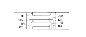
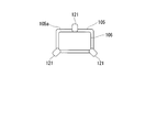
- the non-contact power feeding system according to the fourth embodiment includes a third bag body 121 (shown in FIGS. 8A and 8B), and the third bag body 121 is supplied with gas from the gas supply / exhaust mechanism 108. This is different from the third embodiment.
- Other components are the same as those in the third embodiment. Therefore, in the second embodiment, description of the same components as those in the third embodiment is omitted.
- three third bag bodies 121 are installed on the ground around the first bag body 105.
- the third bag body 121 is hermetically sealed, and is formed so that its tip comes into contact with the peripheral surface of the relay coil 106 when gas (for example, air) is supplied from the gas supply / exhaust mechanism 108. Yes.
- gas for example, air
- the gas supply / exhaust mechanism 108 supplies gas into the third bag body 121 and exhausts gas from the third bag body 121. That is, the gas supply / exhaust mechanism 108 has three supply / exhaust pipes connected to the third bag body 121 in addition to the first bag body 105 and the second bag body 107.
- the power supply control unit 110 of the ground power supply apparatus S completes the gas supply to each third bag body 121 by the gas supply / exhaust mechanism 108. Start supplying.
- the power supply control unit 110 controls the gas supply / exhaust mechanism 108 so as to expand or contract each third bag body 121 based on the power amount notification received by the wireless communication unit 109. That is, the power supply control unit 110 controls the gas supply / exhaust mechanism 108 to inflate or contract each third bag body 121 until the increase in the electric energy indicated by the electric energy notification stops.
- the relay coil 106 moves in the horizontal direction (the feeding coil 104 and the receiving coil depending on the degree of contact by each third bag body 121. 111 in a direction orthogonal to the direction connecting 111). That is, the relay coil 106 moves in the horizontal direction according to the amount of gas supplied to each third bag body 121 by the gas supply / exhaust mechanism 108, and transmission efficiency is improved by stopping the expansion or contraction of the third bag body 121. Stop at the optimal position.
- the power supply control unit 110 causes the power supply circuit 103 to start a power supply operation.
- the relay coil 106 is at a position where the transmission efficiency between the power feeding coil 104 and the power receiving coil 111 is optimal, power is supplied from the power feeding coil 104 to the power receiving coil 111 with high transmission efficiency.
- the power reception calculation control unit 118 of the vehicle M appropriately charges the battery 114 by controlling the charging circuit 113 while monitoring the charging state of the battery 114.
- the power receiving calculation control unit 118 notifies the battery 114 that the battery 114 is fully charged by a display unit (not shown) or the like. Then, when the driver recognizes that the battery is fully charged by an indicator (not shown) or the like, the driver drives the vehicle M and moves from the place where the ground power supply device S is installed.
- the power supply control unit 110 of the ground power supply apparatus S uses the wireless communication unit 109 to communicate with the wireless communication unit 117 of the vehicle M (or the output of a position sensor such as a sound sensor or an optical sensor (not shown)). Is detected, the control of the power feeding circuit 103 is stopped, and the gas supply / exhaust mechanism 108 is controlled to add the first bag body 105 and the second bag body 107, and the third bag body 121 is completely removed. Shrink.
- the third bag body 121 is expanded or contracted by supplying gas, and the relay coil 106 is moved in the horizontal direction, so that non-contact power feeding can be performed more efficiently than in the past. Become.
- the non-contact electric power feeding system which concerns on 5th Embodiment is demonstrated.
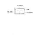
- the first bag body 122 instead of the first bag body 105, the first bag body 122 (FIG. 9A and FIG. 9A and FIG. 9A) divided as viewed from the direction connecting the power feeding coil 104 and the power receiving coil 111. 9B), and is different from the third embodiment in that gas is supplied from the gas supply / exhaust mechanism 108 to the divided regions 122a, 122b, 122c of the first bag body 122.
- Other components are the same as those in the third embodiment. Therefore, in the fifth embodiment, description of the same components as those in the third embodiment is omitted.
- the first bag body 122 is divided into, for example, three (divided regions 122a, 122b, and 122c) when viewed from the direction connecting the power feeding coil 104 and the power receiving coil 111. Further, each divided region 122a, 122b, 122c of the first bag body 122 is sealed, and when gas (for example, air) is supplied from the gas supply / exhaust mechanism 108, the first bag body 122 expands to move the relay coil 106 upward. While lifting, the inclination of the relay coil 106 is changed by the difference in expansion.
- gas for example, air
- the gas supply / exhaust mechanism 108 supplies gas into the respective divided regions 122a, 122b, 122c and the second bag body 107 of the first bag body 122 and at the same time the respective divided regions 122a, 122b, 122c and the first bag body 122 of the first bag body 122.
- the gas is exhausted from the two bag bodies 107. That is, the gas supply / exhaust mechanism 108 has four supply / exhaust pipes connected to the divided regions 122a, 122b, 122c of the first bag body 122 and the second bag body 107, respectively.
- the power supply control unit 110 starts the gas supply to the divided regions 122a, 122b, 122c of the first bag body 122 by the gas supply / exhaust mechanism 108, and the power supply circuit 103 starts a power supply operation of minute electric power.
- the power supply control unit 110 controls the gas supply / exhaust mechanism 108 to expand or contract each of the divided regions 122a, 122b, 122c of the first bag body 122 based on the power amount notification received by the wireless communication unit 109. To do. That is, the power supply control unit 110 controls the gas supply / exhaust mechanism 108 to inflate or contract each third bag body 121 until the increase in the electric energy indicated by the electric energy notification stops.
- the relay coil 106 moves between the power feeding coil 104 and the power receiving coil 111 of the vehicle M by the divided regions 122a, 122b, and 122c, and the relay coil 106 is caused by a difference in expansion between the divided regions 122a, 122b, and 122c. Is changed, and the third bag body 121 stops at a position where the transmission efficiency is optimal by stopping the expansion or contraction of the third bag body 121.
- the power supply control unit 110 causes the power supply circuit 103 to start a power supply operation.
- the relay coil 106 is at a position where the transmission efficiency between the power feeding coil 104 and the power receiving coil 111 is optimal, power is supplied from the power feeding coil 104 to the power receiving coil 111 with high transmission efficiency.
- the power reception calculation control unit 118 of the vehicle M appropriately charges the battery 114 by controlling the charging circuit 113 while monitoring the charging state of the battery 114.
- the power receiving calculation control unit 118 notifies the battery 114 that the battery 114 is fully charged by a display unit (not shown) or the like. Then, when the driver recognizes that the battery is fully charged by an indicator (not shown) or the like, the driver drives the vehicle M and moves from the place where the ground power supply device S is installed.
- the power supply control unit 110 of the ground power supply apparatus S uses the wireless communication unit 109 to communicate with the wireless communication unit 117 of the vehicle M (or the output of a position sensor such as a sound sensor or an optical sensor (not shown)). Is detected, the control of the power supply circuit 103 is stopped and the gas supply / exhaust mechanism 108 is controlled to completely separate the divided regions 122a, 122b, 122c of the first bag body 122 and the second bag body 107. Shrink.
- each divided region 122a, 122b, 122c of the first bag body 122 is expanded or contracted, and the inclination of the relay coil 106 is changed.
- Non-contact power feeding becomes possible.
- the present invention is not limited to the above-described embodiment, and for example, the following modifications can be considered.
- the first bag body 105, the relay coil 106, the second bag body 107, the gas supply / exhaust mechanism 108, the third bag body 121, and the first bag body 122 are ground-fed. Although attached to the device S, it may be attached to the vehicle M.
- the present invention is not limited to this.
- the plurality of relay coils 106 are connected to the power feeding coil 104 and the power receiving coil 111. You may arrange
- the present invention is applied to the non-contact power feeding system in which the power feeding coil 104, the relay coil 106, and the power receiving coil 111 are provided with the coil axis in the vertical direction.
- the present invention is not limited to this.
- the present invention may be applied to a non-contact power feeding system in which the power feeding coil 104, the relay coil 106, and the power receiving coil 111 are provided in a posture (horizontal posture) in which the coil axis is a horizontal direction or an inclined posture.
- the power feeding device is the ground power feeding device S embedded in the ground, and the power receiving device is the vehicle M traveling on the ground.
- the power feeding device may be an underwater power feeding device installed underwater, and the power receiving device may be an underwater vehicle that moves underwater.
- the underwater vehicle must take out water quality data when investigating the water quality in the water.
- a communication antenna is provided in any one of the first bag body 105, the second bag body 107, the third bag body 121, and the first bag body 122 provided in the underwater vehicle and the underwater power feeding device. Water quality data may be taken out via the.
- the underwater power supply device is wired to a ground water quality data management device or the like via a communication cable, and the water quality data is transmitted via the communication antenna when the underwater vehicle is transmitting power (when the battery 114 is charged).
- the water quality data received from the underwater vehicle via the communication antenna may be wired to the water quality data management device or the like.
- the fluid supplied into the 1st bag body 105, the 2nd bag body 107, the 3rd bag body 121, or the 1st bag body 122 may be liquid other than a gas body.
- this liquid may be an ionic liquid (for example, salt water), distilled water, alcohol, or the like as long as it does not damage the coil and each bag.
- the specific gravity of the gas and the liquid is different, the balance of the weights of the power feeding device and the power receiving device can be adjusted by using the gas and the liquid together.
- the non-contact power feeding system includes a ground power feeding device S (power feeding device) embedded in the ground G and a vehicle M (power receiving device) that receives power from the ground power feeding device S. I have.
- This non-contact power feeding system performs non-contact power feeding from the ground power feeding device S to the vehicle M based on a magnetic field resonance method which is one of the non-contact power feeding methods.
- the ground power supply device S is embedded in, for example, a stop position at an intersection or railroad crossing, or a parking / parking position of a parking lot, and performs non-contact power feeding to the vehicle M parked and parked at the parking / stopping position.
- the ground power supply device S includes a power source 201, a rectifier circuit 202, a power supply circuit 203, a power supply coil 204, a bag body (first bag body) 205, a spacer 206, a gas supply / exhaust mechanism 207, and a power supply unit.
- a control unit 208 is provided.
- the gas supply / exhaust mechanism 207 is a gas supply unit in the present embodiment.
- the power source 201 is an AC power source that supplies AC power necessary for power supply to the vehicle M to the rectifier circuit 202, and an output end of the power source 201 is connected to an input end of the rectifier circuit 202.
- the power source 201 is a system power source or a power generator that supplies three-phase AC power such as 200 V or 400 V or single-phase AC power of 100 V, for example.
- the input terminal of the rectifier circuit 202 is connected to the power supply 201, and the output terminal is connected to the power supply circuit 203.
- the rectifier circuit 202 rectifies AC power supplied from the power source 201 and converts it into DC power, and outputs the DC power to the power feeding circuit 203.
- a DC power source such as a solar battery may be used as the power source 201, and the rectifier circuit 202 may be omitted (that is, DC power is supplied from the DC power source to the power feeding circuit 203).
- the power source 201 and the rectifier circuit 202 may be separated from the power feeding circuit 203 and installed without being embedded in the ground G.
- the power supply circuit 203 includes a power supply coil 204 and a resonance capacitor that forms a power supply side resonance circuit, and the DC power supplied from the rectifier circuit 202 based on a control command input from the power supply control unit 208 is supplied to the power supply 201.
- This is a kind of inverter that converts AC power (high frequency power) having a frequency higher than that of AC power and supplies the power to the feeding coil 204.
- the power feeding circuit 203 is installed on the ground G at the parking / stopping position, and is connected to the power feeding coil 204 by a flexible electric cable. Note that the power feeding circuit 203 may be embedded in the ground G instead of on the ground G, or a flexible electrical cable may be extended to install the power feeding circuit 203 away from the ground G. .
- the feeding coil 204 is a circular type coil or a solenoid type coil.
- the coil axis is set in a vertical direction (vertical direction), and in the case of a solenoid type coil, the coil axis is set in a horizontal direction.
- the bag body 205 in an exposed state or in a state molded with a nonmagnetic and nonconductive material such as plastics, fiber reinforced plastics, ceramics or a composite material thereof (FIGS. 11A and 11B). And FIG. 12).
- Both ends of the power supply coil 204 are connected to the output terminal of the power supply circuit 203, and the power supply coil 204 generates a magnetic field by being supplied with high-frequency power from the power supply circuit 203, so that it does not contact the vehicle M. Supply power.
- the bag body 205 is a kind of balloon in which a stretchable elastic material such as rubber is formed into a film shape, and is installed on the ground G.
- the bag body 205 supports the power supply coil 204 by installing the power supply coil 204 in contact with one end face (lower surface) of the upper side 205a (see FIGS. 11A, 11B, and 12).
- the bag body 205 is sealed, and when gas (for example, air) is supplied from the gas supply / exhaust mechanism 207, the bag body 205 expands and lifts the power supply coil 204 upward, thereby causing the power supply coil 204 to be described later. It moves toward the receiving coil 211.
- gas for example, air
- the spacer 206 is a plate-like member having a specific hardness that does not decrease the efficiency of non-magnetic and non-conductive non-contact power feeding, such as plastic, and is disposed on the other end surface (upper surface) of the power feeding coil 204. And is supported by the feeding coil 204 (see FIGS. 11A, 11B, and 12).
- the specific hardness means a hardness that hardly deforms when the bag 205 expands and presses the spacer 206 against the power receiving coil 211.
- the spacer 206 is formed to have a thickness equivalent to the distance at which the transmission efficiency of non-contact power feeding between the power feeding coil 204 and the power receiving coil 211 of the vehicle M is optimal.
- the upper surface 206a of the spacer 206 is formed flat so that the posture is stable when coming into contact with the power receiving coil 211 and does not get in the way when the vehicle M passes over the upper surface 206a.
- the gas supply / exhaust mechanism 207 is a type of pump that supplies gas into the bag body 205 and exhausts gas from the bag body 205 based on a control command input from the power supply control unit 208.
- a pressure gauge is provided at a supply port of a pump that supplies gas to the bag body 205, and a detection result (detection signal) by the pressure gauge is output to the power supply control unit 208.
- the gas supply / exhaust mechanism 207 has a valve that can be opened and closed by a command from the power supply control unit 208 to exhaust gas, for example, a valve that can be opened and closed by an electric signal.
- the power supply control unit 208 includes a microprocessor, a memory, and the like, and is a software type control device that functions based on a power supply control program, and controls the power supply circuit 203 and the gas supply / exhaust mechanism 207. Details of the processing of the power supply control unit 208 will be described later.
- the vehicle M is an automobile that is driven by a driver and travels on a road.
- the vehicle M is an electric car or a hybrid car that travels using a battery as a power source.
- the vehicle M includes a power receiving coil 211, a power receiving circuit 212, a charging circuit 213, a battery 214, and a power receiving control unit 215.
- the vehicle M naturally includes components necessary for traveling such as a traveling motor, an operation handle, a brake, and an engine in the case of a hybrid vehicle.
- the power receiving coil 211 is a circular type coil or a solenoid type coil.
- the power receiving coil 211 is a circular type coil or a solenoid type coil. It is provided at the bottom of the vehicle M in such a posture that the axis is in the vertical direction (vertical direction), and in the case of a solenoid type coil, the coil axis is horizontal and parallel to the coil axis of the power feeding coil 204. Both ends of the power receiving coil 211 are connected to the input terminals of the power receiving circuit 212.
- the magnetic field of the power feeding coil 204 acts, an electromotive force is generated by electromagnetic induction, and the electromotive force is output to the power receiving circuit 212.
- the feeding coil 204 and the receiving coil 211 are both of the same type, that is, either a circular coil or a solenoid coil, but the sizes of the feeding coil 204 and the receiving coil 211 are the same.
- the shape may be the same or different as long as highly efficient non-contact power feeding is possible.
- the input terminal of the power receiving circuit 212 is connected to both ends of the power receiving coil 211, and the output terminal is connected to the input terminal of the charging circuit 213.
- This power receiving circuit 212 is a kind of rectifier circuit that includes a power receiving coil 211 and a resonance capacitor that constitutes a power receiving side resonance circuit, and converts AC power supplied from the power receiving coil 211 into DC power and supplies it to the charging circuit 213. is there.
- the capacitance of the resonance capacitor of the power reception circuit 212 is equal to or substantially the same as the resonance frequency of the power supply side resonance circuit and the resonance frequency of the power reception side resonance circuit so that highly efficient non-contact power supply is possible. It is set to be.
- the charging circuit 213 is a kind of DC-DC converter that converts the power (DC power) supplied from the power receiving circuit 212 into a voltage suitable for charging the battery 214 and charges the battery 214, and its input terminal is the power receiving circuit 212. The output terminal is connected to the input terminal of the battery 214.
- the battery 214 is a rechargeable battery (for example, a secondary battery such as a lithium ion battery or a nickel metal hydride battery) mounted on the vehicle M, and supplies driving power to a travel motor or the like (not shown).
- the power reception control unit 215 is a software-type control device that includes a microprocessor, a memory, and the like and functions based on a power reception control program, and controls the charging circuit 213.
- the power reception control unit 215 of the vehicle M stops the charging circuit 213 when power is not supplied (for example, during normal operation of the vehicle M by the driver).
- the power supply control unit 208 of the ground power supply apparatus S stops the power supply circuit 203 when the power is not supplied, that is, when the vehicle M to be supplied is not parked at the parking position, and the bag body 205 is completely
- the gas supply / exhaust mechanism 207 exhausts the gas in the bag body 205 so as to contract. This can be realized by opening an openable / closable valve for gas exhaust.
- the power reception control unit 215 of the vehicle M grasps the installation position of the ground power supply apparatus S from the output of a position sensor such as a sound wave sensor or an optical sensor (not shown).
- a position sensor such as a sound wave sensor or an optical sensor (not shown).
- the charging circuit 213 starts the charging operation.
- the output of the charging circuit 213 is also zero, and no power is supplied to the battery 214.
- the power supply control unit 208 of the ground power supply apparatus S grasps the position of the vehicle M from the output of a position sensor such as a sound wave sensor or an optical sensor (not shown) as with the vehicle M.
- a position sensor such as a sound wave sensor or an optical sensor (not shown)
- the power supply control unit 208 detects that the vehicle M has moved above the ground power supply device S from the output of a position sensor such as a sound wave sensor or an optical sensor
- the gas supply / exhaust mechanism 207 so that the bag 205 expands.
- the openable / closable valve for exhausting the gas is closed.
- the power supply control unit 208 controls the gas supply / exhaust mechanism 207 based on a detection signal input from the pressure gauge of the gas supply / exhaust mechanism 207. That is, the power supply control unit 208 causes the gas supply / exhaust mechanism 207 to supply gas until the detection result by the pressure gauge reaches a specific pressure. Accordingly, the power feeding coil 204 is lifted upward by the inflated bag body 205 and moves toward the power receiving coil 211.
- the power supply control unit 208 stops the gas supply when a specific pressure is reached.
- the specific pressure is a pressure determined by the elastic modulus of the material of the bag body 205. If the bag body 205 is not deformed and the gas is continuously supplied, the elastic limit of the bag body 205 is exceeded and breakage occurs. The pressure is such that As a result, as shown in FIG. 12, the upper surface 206 a of the spacer 206 is in contact with the power receiving coil 211 of the vehicle M, and the power feeding coil 204 and the power receiving coil 211 are arranged to face each other with the spacer 206 therebetween. That is, the power feeding coil 204 and the power receiving coil 211 are arranged to face each other with a distance that optimizes the transmission efficiency in the magnetic field resonance method.
- the power supply control unit 208 causes the power supply circuit 203 to start a power supply operation.
- the power feeding coil 204 and the power receiving coil 211 are arranged to face each other with a distance such that the transmission efficiency in the magnetic field resonance method is optimal, power is transferred from the power feeding coil 204 to the power receiving coil 211 with high transmission efficiency. Is supplied.
- power is output from the power receiving circuit 212, the charging circuit 213 starts supplying power to the battery 214, and charging of the battery is started.
- the power reception control unit 215 of the vehicle M appropriately charges the battery 214 by controlling the charging circuit 213 while monitoring the charging state of the battery 214.
- the power reception control unit 215 notifies the battery 214 that the battery 214 is fully charged by a display unit (not shown) or the like.
- the power supply control unit 208 of the ground power supply apparatus S stops the control of the power supply circuit 203 and controls the gas supply / exhaust mechanism 207 to completely contract the bag body 205. For example, by stopping the pump and opening an openable / closable valve for exhausting the gas, the gas in the bag body 205 is extracted and completely contracted.
- an indicator not shown
- the power supply control unit 208 of the ground power supply device S includes a sound wave sensor (not shown).
- the control of the power feeding circuit 203 is stopped, and the gas supply / exhaust mechanism 207 is controlled to completely contract the bag body 205, so that the spacer 206 And the power receiving coil 211 are prevented from coming into contact with each other.
- the gas in the bag body 205 is extracted and completely contracted.
- the bag body 205 is inflated, so that the power feeding coil 204 and the power receiving coil 211 are arranged in contact with each other with a distance such that the transmission efficiency is optimal via the spacer 206. Power can be supplied.
- the gas in the bag body 205 is also elastic and allows deformation of the bag body 205, so that the spacer 206, the power feeding coil 204, and the power receiving coil 211 are used. It is possible to prevent mechanical damage from being applied due to excessive force.
- the present embodiment it is possible to reduce the price of the vehicle M and simplify the configuration by not providing the vehicle height adjustment mechanism, and it is also possible to reduce the amount of splashed mud, stone, etc. because no height sensor is provided.
- the height sensor is not soiled or damaged by foreign matter.
- the non-contact electric power feeding system which concerns on 7th Embodiment is demonstrated.
- the non-contact power feeding system according to the seventh embodiment includes a point where the power feeding circuit 203 is embedded in the ground G, and a position where the bag body 205 is parked and stopped (where the vehicle M can stop). )
- the ground G instead of the ground G, that is, the feeding coil 204, the bag 205 and the spacer 206 are accommodated in the concave C, and a new movement restricting portion.
- the second embodiment is different from the sixth embodiment in that 209 is provided in the recess C.
- Other components are the same as those in the sixth embodiment. Therefore, in the seventh embodiment, the description of the same components as in the sixth embodiment is omitted.
- the power feeding circuit 203 converts the DC power supplied from the rectifier circuit 202 into AC power (high frequency power) based on a control command input from the power feeding control unit 208 and converts it to the power feeding coil 204. It is a kind of inverter to be supplied, and is connected to the feeding coil 204 by a flexible electric cable. Further, unlike the sixth embodiment, the power feeding circuit 203 is embedded in the ground G near the recess C.
- the power supply coil 204 is a circular coil or a solenoid type coil that supplies power to the vehicle M in a non-contact manner by generating a magnetic field when high-frequency power is supplied from the power supply circuit 203. . Further, unlike the sixth embodiment, the power supply coil 204 is accommodated in the recess C when the bag body 205 contracts.
- the bag body 205 supports the power supply coil 204 by arranging the power supply coil 204 in contact with the upper surface 205a so that one end surface (lower surface) thereof is in contact with the upper surface 205a.
- the bag body 205 expands and lifts the power supply coil 204 upward, thereby moving the power supply coil 204 toward the power reception coil 211.
- the bag body 205 is installed at the bottom of the recess C instead of the ground G.
- the spacer 206 is disposed on the other end surface (upper surface) of the power feeding coil 204 and has the same thickness as the distance at which the transmission efficiency between the power feeding coil 204 and the power receiving coil 211 of the vehicle M is optimal. Is formed. Further, unlike the sixth embodiment, the spacer 206 is accommodated in the recess C when the bag body 205 contracts.
- the movement restricting unit 209 is installed on the inner side surface of the recess C facing the peripheral surface of the power supply coil 204, and restricts the movement of the power supply coil 204 accommodated in the recess C in the horizontal direction.
- the power supply coil 204 is dragged by the vehicle M and moves in the recess C when the wheel contacts the spacer 206.
- the movement restricting unit 209 restricts the power feeding coil 204 from being dragged and moved by the vehicle M in this way.
- the movement restricting portion 209 is made of an elastic member such as rubber or sponge.
- the operation of the seventh embodiment configured as described above will be described. Note that description of operations similar to those of the sixth embodiment is omitted.
- the power supply control unit 208 of the ground power supply device S detects that the vehicle M has moved above the ground power supply device S from the output of a position sensor such as a sound wave sensor or an optical sensor (not shown), the bag body 205 is completely removed. Gas is supplied to the gas supply / exhaust mechanism 207 so as to expand.
- the power supply control unit 208 controls the gas supply / exhaust mechanism 207 based on a detection signal input from the pressure gauge of the gas supply / exhaust mechanism 207. That is, the power supply control unit 208 causes the gas supply / exhaust mechanism 207 to supply gas until the detection result by the pressure gauge reaches a specific pressure. Accordingly, the power feeding coil 204 is lifted upward by the inflated bag body 205 and moves toward the power receiving coil 211.
- the power supply control unit 208 stops the gas supply when a specific pressure is reached.
- the upper surface 206 a of the spacer 206 is in contact with the power receiving coil 211 of the vehicle M, and the power feeding coil 204 and the power receiving coil 211 are arranged to face each other with the spacer 206 therebetween. That is, the power feeding coil 204 and the power receiving coil 211 are arranged to face each other with a distance at which the transmission efficiency in the magnetic field resonance method is optimal.
- the power supply control unit 208 causes the power supply circuit 203 to start a power supply operation.
- the power feeding coil 204 and the power receiving coil 211 are arranged to face each other with a distance at which the transmission efficiency in the magnetic field resonance method is optimal, power is supplied from the power feeding coil 204 to the power receiving coil 211 with high transmission efficiency. .
- the power reception control unit 215 of the vehicle M appropriately charges the battery 214 by controlling the charging circuit 213 while monitoring the charging state of the battery 214.
- the power reception control unit 215 notifies the battery 214 that the battery 214 is fully charged by a display unit (not shown) or the like. Then, when the driver recognizes that the battery is fully charged by an indicator (not shown) or the like, the driver drives the vehicle M and moves from the place where the ground power supply device S is installed.
- the power supply circuit 203 is embedded in the ground G, and the power supply coil 204, the bag body 205, and the spacer 206 are accommodated in the recess C, the wheels of the vehicle M are connected to the power supply circuit 203, the power supply coil 204, the bag. Colliding with the body 205 and the spacer 206 can be avoided. Even when the wheel of the vehicle M passes over the recess C, the movement restriction unit 209 restricts the movement of the power supply coil 204 in the horizontal direction, so that the power supply coil 204 can be prevented from being dragged by the vehicle M. .
- the power feeding coil 204 and the power receiving coil 211 can be opposed to each other with a distance at which the transmission efficiency is optimal via the spacer 206. Further, according to the present embodiment, it is possible to reduce the price of the vehicle and simplify the configuration by not providing the vehicle height adjustment mechanism, and since no height sensor is provided, foreign matter such as splashed mud or stone As a result, the height sensor is not soiled or damaged.
- the power supply circuit 203 is embedded in the ground G, and the power supply coil 204, the bag body 205, and the spacer 206 are accommodated in the recess C, so that the wheels of the vehicle M and the like can be connected to the power supply circuit 203. Since it can avoid colliding with the feeding coil 204, the bag body 205, and the spacer 206, it does not interfere with the traveling of the vehicle M. In addition, according to the present embodiment, even when the wheel of the vehicle M passes over the recess C, the movement restriction unit 209 restricts the movement of the power supply coil 204 in the horizontal direction. Can be avoided.
- the spacer 206 may be detachable.
- the spacer 206 may be detachable in magnetic field resonance type non-contact power feeding, when there are a plurality of standards having different transmission efficiency distances between the power feeding coil 204 and the power receiving coil 211 (for example, when the size and shape of the power receiving coil 211 differ depending on the standard).
- the spacers 206 having different thicknesses may be replaced according to the standard.
- the present invention is applied to the non-contact power feeding system provided with the ground power feeding device S provided, the present invention is not limited to this.
- the present invention is applied to a non-contact power supply system including a ground power supply device S provided in a posture (horizontal posture) or an inclined posture with a coil axis as a horizontal direction. Also good.
- the spacer 206 is installed on one end face of the feeding coil 204 in a horizontal posture or an inclined posture, and the bag body 205 is placed between the wall for attaching the feeding coil 204 and the other end face of the feeding coil 204. Also good.
- the spacer 206 is a plate-like member, but the present invention is not limited to this.
- the spacer 206 may be a bar-like member having the same height as the distance at which the transmission efficiency between the power feeding coil 204 and the power receiving coil 211 of the vehicle M is optimal.
- the spacer 206 is in contact with the power receiving coil 211 when the bag body 205 is inflated, but the spacer 206 may be in contact with the bottom surface of the vehicle M.
- the distance between the power supply coil 204 and the power reception coil 211 that optimizes transmission efficiency. You may make it the state arrange
- the power feeding device is the ground power feeding device S embedded in the ground, and the power receiving device is the vehicle M traveling on the ground.
- the power feeding device may be an underwater power feeding device installed underwater, and the power receiving device may be an underwater vehicle that moves underwater.
- the underwater vehicle must take out water quality data when investigating the water quality in the water.
- a communication antenna may be provided inside the bag body 205 provided in the underwater power feeding device, and water quality data may be taken out via the communication antenna.
- the underwater power supply device is wired to a ground water quality data management device or the like via a communication cable, and the water quality data is transmitted via the communication antenna when the underwater vehicle is transmitting power (when the battery 214 is charged).
- the water quality data received from the underwater vehicle via the communication antenna may be wired to the water quality data management device or the like.
- the fluid supplied into the bag body 205 may be a liquid other than the gas body.
- this liquid may be an ionic liquid (for example, salt water) as long as it does not damage the bag body 205, or may be distilled water or alcohol.
- the specific gravity of the gas and the liquid is different, the balance of the weight of the power feeding device can be adjusted by using the gas and the liquid together.
- FIG. 14 is a block diagram showing a main configuration of a non-contact power feeding system 301 according to the eighth embodiment of the present invention. As shown in FIG.
- the non-contact power supply system 301 includes a power supply device 310 installed on the ground side, a balloon 320 corresponding to the second bag body in the first to fifth embodiments, a power supply gas supply / exhaust device 330, and A magnetic body unit 340 and a power receiving device 350 mounted on the vehicle M (moving body) side are provided, and power is supplied from the power feeding device 310 to the power receiving device 350 in a non-contact manner.
- the power feeding device 310 includes a power source 311, a rectifier circuit 312, a power feeding circuit 313, a power feeding control unit 314, and a power feeding coil 315, and generates power suitable for non-contact power feeding to the power receiving device 350 and also to the power receiving device 350.
- Various controls necessary for contactless power feeding are performed.
- the power supply apparatus 310 is described as being installed on the ground. However, the power supply apparatus 310 may be installed in the basement, and is installed above the vehicle M (for example, the ceiling). Also good.
- the output terminal of the power source 311 is connected to the input terminal of the rectifier circuit 312, and the power source 311 supplies AC power necessary for power feeding to the power receiving device 350 to the rectifier circuit 312.
- the power source 311 is a system power source that supplies three-phase AC power such as 200 V or 400 V or single-phase AC power of 100 V, for example.
- the input terminal of the rectifier circuit 312 is connected to the power supply 311 and the output terminal is connected to the power supply circuit 13.
- the rectifier circuit 312 rectifies and converts AC power supplied from the power supply 311 into DC power. The direct current power thus output is output to the power feeding circuit 313.
- the input terminal of the power supply circuit 313 is connected to the rectifier circuit 312 and the output terminal is connected to both ends of the power supply coil 315.
- the power supply circuit 313 converts the DC power from the rectifier circuit 312 into AC power and converts it. AC power is output to the feeding coil 315.
- the power supply circuit 313 includes a resonance capacitor that forms a power supply side resonance circuit together with the power supply coil 315, and direct current power from the rectifier circuit 312 is supplied to the power supply 311 under the control of the power supply control unit 314. It is converted into AC power (high frequency power) having a frequency higher than that of AC power, and is output to the feeding coil 315.
- the power feeding control unit 314 controls the power feeding circuit 313 to generate power to be supplied to the power receiving device 350.
- the power supply control unit 314 includes a CPU (Central Processing Unit), a memory, and the like, and performs the above-described various controls based on a control program prepared in advance.
- the power supply control unit 314 controls the power supply gas supply / exhaust device 330 to inflate or deflate the balloon 320. Further, the power supply control unit 314 also controls the magnetic unit 340.
- the feeding coil 315 is a helical coil having a coil shape dimension defined in advance.
- the power feeding coil 315 may be provided integrally with a cover formed of a nonmagnetic material such as plastic that molds the power feeding coil 315.
- the power supply coil 315 supplies power to the power receiving device 350 in a non-contact manner by generating a magnetic field corresponding to the high frequency power supplied from the power supply circuit 313.
- the feeding coil 315 is a so-called solenoid type coil in which the winding axis direction is in the horizontal direction.
- the balloon 320 is fixed to the ground side so as to cover the power supply coil 315, and expands (swells) when gas is supplied from the power supply gas supply / exhaust device 330 to the inside, and the supplied gas is also supplied with power.
- the gas supply / exhaust device 330 contracts (shrinks) when sucked.
- the balloon 320 is made of, for example, a rubber material having elasticity. Note that the balloon 320 may be formed using rubber obtained by synthesizing aluminum powder or copper powder, except for a magnetic path connecting the power feeding coil 315 and the power receiving coil 351. Thereby, the leakage electromagnetic field can be reduced.
- the power supply gas supply / exhaust device 330 supplies and exhausts gas to / from the balloon 320 under the control of the power supply control unit 314. As shown in FIG. 14, the power supply gas supply / exhaust device 330 is connected to the balloon 320 via a supply / exhaust pipe, and supplies / exhausts gas to / from the balloon 320 via the supply / exhaust pipe.
- FIGS. 15A and 15B are enlarged schematic views including the magnetic unit 340, FIG. 15A is a perspective view, and FIG. 15B is a side view.
- the magnetic body unit 340 is installed on the ground side, and as shown in FIGS. 15A and 15B, a magnetic body housing part 341 (magnetic body housing bag), a magnetic body supply device 342, and a recovery valve 343 (recovery valve 343) Means).
- the magnetic body accommodating portion 341 is a member that expands or contracts when the air is supplied / exhausted from the magnetic body supply device 342, and is connected to the magnetic body supply device 342.
- the magnetic body accommodating portion 341 is provided so as to be disposed on both sides of the power feeding coil 315 and in the middle of a magnetic path formed between the power feeding coil 315 and the power receiving coil 351 when expanded. . Further, when the magnetic material accommodating portion 341 is contracted, it is disposed so as not to disturb the contraction of the balloon 320 as shown in FIG.
- These magnetic body accommodation portions 341 can accommodate the powdered magnetic body X supplied from the magnetic body supply device 342 when expanded. Note that an exhaust path having a filter (not shown) is connected to the magnetic body accommodating portion 341, and the magnetic body X can be supplied even when it is expanded.
- the magnetic substance supply device 342 is connected to the magnetic substance accommodating part 341, and supplies the powdery magnetic substance X and gas to the magnetic substance accommodating part 341 under the control of the power supply control part 314.
- the magnetic body housing part 341 expands and the magnetic body X is supplied to the magnetic body housing part 341.
- the magnetic body storage unit 341 adjusts the amount of the magnetic body X supplied to the magnetic body storage unit 341 under the control of the power supply control unit 314. Further, the magnetic body housing part 341 contracts the magnetic body housing part 341 by sucking the gas supplied to the magnetic body housing part 341.
- the recovery valve 343 is installed below each magnetic material storage unit 341. When the recovery valve 343 is opened, the magnetic material X stored in the magnetic material storage unit 341 is dropped and recovered in the magnetic material supply device 342.
- the magnetic body unit 340 when a magnetic path is formed between the power feeding coil 315 and the power receiving coil 351 in a state where the magnetic body X is housed in the magnetic body housing portion 341, as shown in FIG.
- the body accommodating portion 341 is disposed in the middle of the magnetic path.
- the magnetic body X accommodated in the magnetic body accommodating portion 341 is magnetized, and an area having a lower magnetic permeability than air is generated.
- the magnetic resistance between the power feeding coil 315 and the power receiving coil 351 is reduced.
- the vehicle M is an automobile that is driven by a driver and travels on a road.
- the vehicle M is an electric car or a hybrid car that includes a travel motor as a power generation source.
- the vehicle M includes a power receiving device 350 as shown in FIG. Although omitted in FIG. 14, the vehicle M has a configuration necessary for traveling, such as an engine, the traveling motor, the operation handle, and a brake.
- the power receiving device 350 includes a power receiving coil 351, a power receiving circuit 352, a charging circuit 353, a battery 354, and a power receiving control unit 355.
- the power receiving coil 351 is formed of a helical coil having substantially the same coil diameter as that of the power feeding coil 315 described above.
- the power receiving coil 351 may be provided integrally with a cover formed of a nonmagnetic material such as plastic that molds the power receiving coil 351.
- the power receiving coil 351 is provided at the bottom of the vehicle M so that the coil axis is in the vertical direction (vertical direction) so that the power receiving coil 315 can face the power feeding coil 315.
- the power receiving coil 351 is connected at both ends to the input terminal of the power receiving circuit 352, generates an electromotive force when the magnetic field of the power feeding coil 315 acts, and outputs the generated electromotive force to the power receiving circuit 352.
- the power receiving coil 351 is a so-called solenoid type coil in which the winding axis direction is in the horizontal direction.
- the input terminal of the power receiving circuit 352 is connected to both ends of the power receiving coil 351 and the output terminal is connected to the input terminal of the charging circuit 353.
- the power receiving circuit 352 converts the AC power supplied from the power receiving coil 351 into DC power.
- the converted DC power is output to the charging circuit 353.
- the power reception circuit 352 includes a resonance capacitor that constitutes a power reception resonance circuit together with the power reception coil 351. Note that the capacitance of the resonance capacitor of the power reception circuit 352 is set so that the resonance frequency of the power reception side resonance circuit is the same as the resonance frequency of the power supply side resonance circuit described above.
- the input terminal of the charging circuit 353 is connected to the output terminal of the power receiving circuit 352 and the output terminal is connected to the input terminal of the battery 354, and the charging circuit 353 supplies the power (DC power) from the power receiving circuit 352 to the battery 354.
- the battery 354 is a rechargeable battery (for example, a secondary battery such as a lithium ion battery or a nickel metal hydride battery) mounted on the vehicle M, and supplies power to a travel motor (not shown).
- the power reception control unit 355 includes a CPU, a memory, and the like, and controls the charging circuit 353 based on a power reception control program prepared in advance.
- the power receiving control unit 355 controls the power receiving device 350 to stop the charging circuit 353 at the time of non-power feeding (for example, during normal operation of the vehicle M by the driver). Is called.
- the power feeding control unit 314 performs control to stop the power feeding circuit 313 when power is not supplied (that is, when the vehicle M to be fed is not parked at the parking / stopping position).
- the installation position of the power supply coil 315 is grasped by the power reception control unit 355.
- ascertaining the installation position of the feed coil 315 is mentioned, for example.
- the position of the vehicle M is grasped by the power supply control unit 314 from the output of a position sensor such as a sound wave sensor or an optical sensor (not shown).
- a position sensor such as a sound wave sensor or an optical sensor (not shown).
- the power supply control unit 314 performs control to supply gas from the power supply gas supply / exhaust device 330 to the balloon 320.
- the balloon 320 is inflated.
- the power supply control unit 314 performs control to supply the gas and the magnetic material X from the magnetic material supply device 342 to the magnetic material storage unit 341.
- the magnetic body accommodating portion 341 expands, and the magnetic body X made of powder is accommodated in the magnetic body accommodating portion 341.
- the power supply circuit 313 of the power supply apparatus 310 is controlled by the power supply control unit 314 to start the power supply operation. Thereby, electric power is supplied from the power feeding coil 315 to the power receiving coil 351 installed in the vehicle M without contact.
- the power reception control unit 355 controls the charging circuit 353 while monitoring the charging state of the battery 354, thereby charging the battery 354.
- the power reception control unit 355 When the power reception control unit 355 detects that the battery 354 is fully charged, it performs control to stop the charging circuit 353 and, at the same time, an indicator (not shown) or the like (for example, charging the battery 354 provided in the driver's seat). Status indicator) that the battery 354 is fully charged. With this notification, the driver can recognize that the battery 354 is fully charged.
- the power supply control unit 314 of the power supply apparatus 310 determines whether or not the power supply is completed while the non-contact power supply is performed.
- the determination as to whether or not the power supply has ended can be made based on, for example, whether or not the amount of power supplied to the vehicle M has suddenly decreased. If it is determined that the power supply has not been completed, the power supply control unit 314 controls the power supply circuit 313 to continue the non-contact power supply. On the other hand, when it is determined that the power supply has been completed, the power supply control unit 314 controls the power supply circuit 313 to stop the power supply operation.
- the power supply control unit 314 opens the recovery valve 343 to recover the magnetic body X, and exhausts the gas supplied into the magnetic body storage unit 341 to the magnetic body supply device 342 so that the magnetic body is discharged.
- the accommodating part 341 is contracted.
- the power supply control unit 314 causes the gas supplied into the balloon 320 to be exhausted to the power supply gas supply / exhaust device 330 to contract the balloon 320. Accordingly, the driver can drive the vehicle M and move from the place where the feeding coil 315 is installed.
- the non-contact power feeding system 301 of the present embodiment as described above includes the magnetic body X disposed in the middle of a magnetic path formed between the power feeding coil 315 and the power receiving coil 351.
- the magnetic body X is magnetized by being placed in the middle of the magnetic path, and forms a region having a lower magnetic permeability than air. Due to this region, the magnetic resistance between the feeding coil 315 and the receiving coil 351 is lowered. Therefore, according to the non-contact power feeding system 301 of the present embodiment, a large amount of power can be transmitted even when the distance between the power feeding coil 315 and the power receiving coil 351 is long by appropriately adjusting the impedance of the system. It becomes possible.
- the magnetic body X is made of powder, and is disposed in the middle of the magnetic path when the balloon 320 is inflated and can store the magnetic body X. 341 and a magnetic material supply device 342 that supplies the magnetic material X to the magnetic material accommodating portion 341. For this reason, the supply amount of the magnetic body X from the magnetic body supply device 342 to the magnetic body accommodating portion 341 can be adjusted, and the magnetic resistance between the power feeding coil 315 and the power receiving coil 351 can be optimally adjusted. .
- the non-contact power supply system 301 of the present embodiment includes a recovery valve 343. For this reason, it is possible to collect or reduce the magnetic material X accommodated in the magnetic material accommodating portion 341.
- the non-contact power feeding system 301 is a bag body (magnetic body housing bag body) in which the magnetic body housing portion 341 is expanded and contracted together with the balloon 320. For this reason, it can prevent that the magnetic body accommodating part 341 inhibits expansion
- FIG. 1 magnetic body housing bag body
- FIG. 17A is an enlarged schematic view including a magnetic body unit 340A included in the non-contact power feeding system of this embodiment.
- a feeding coil 315A made of a so-called circular type coil is installed in which the winding axis direction is the vertical direction.
- the magnetic unit 340 includes a first magnetic body accommodating portion 344 that stands up so as to surround the power supply coil 315A when expanded, and a first magnetic body unit 340 disposed above the power supply coil 315A when expanded. 2 magnetic body accommodation part 345, and connection part 346 which connects these 1st magnetic body accommodation part 344 and 2nd magnetic body accommodation part 345 are provided.
- the inside of the 1st magnetic body accommodating part 344 and the 2nd magnetic body accommodating part 345 is connected via the inside of the connection part 346.
- FIG. 17B the power receiving coil 351A mounted on the vehicle M is also a so-called circular type coil in which the winding axis direction is the vertical direction.
- the first magnetic body accommodating portion 344 is located in the middle of the magnetic path formed between the power feeding coil 315A and the power receiving coil 351A.
- the second magnetic body accommodating portion 345 are disposed.
- the magnetic body X is supplied from the magnetic body supply device 342 to the first magnetic body housing portion 344 and the second magnetic body housing portion 345.
- a balloon and an air supply / exhaust device may be further provided on the power supply coil 315 side.
- a communication antenna may be installed in the balloon 320.
- the balloon 320 and the power receiving coil 351 or the power receiving coil 351A may be firmly fixed by a jamming transition phenomenon by supplying powder into the inflated balloon 320 and then sucking the gas in the balloon 320.
- the structure whose mobile body of this invention is a vehicle was demonstrated.
- the present invention is not limited to this, and the moving body of the present invention may be an underwater moving body.
- ADVANTAGE OF THE INVENTION it is possible to implement
- non-contact power feeding can be performed more efficiently than in the past.
- the feeding coil and the receiving coil can be arranged to face each other with a high transmission efficiency.
- the height sensor is not soiled or damaged by foreign matter such as splashed mud or stone.
- by appropriately adjusting the impedance of the non-contact power feeding system it is possible to transmit a large amount of power even when the distance between the power feeding coil and the power receiving coil is long.
- Non-contact electric power feeding system 20,104,204,315 Feed coil 30a Inner balloon (1st bag body) 30b Outer balloon (second bag) 40 Power supply / exhaust device 50, 111, 211, 351 Power supply coil 60 Auxiliary balloon 70 Housing mechanism 105 First bag body 106 Relay coil 107 Second bag body 108, 207 Gas supply / exhaust mechanism 121 Third bag body 205 Bag body (First bag) 206 Spacer 206a Upper surface 209 of the spacer Movement restriction part 320 Balloon (second bag) 341 Magnetic body housing part (magnetic body housing bag) 342 Magnetic body supply device 343 Recovery valve (recovery means) C Concavity M Vehicle (power receiving device, moving body) S Ground feeder X Magnetic body
Landscapes
- Engineering & Computer Science (AREA)
- Power Engineering (AREA)
- Computer Networks & Wireless Communication (AREA)
- Transportation (AREA)
- Mechanical Engineering (AREA)
- Physics & Mathematics (AREA)
- Electromagnetism (AREA)
- Electric Propulsion And Braking For Vehicles (AREA)
- Charge And Discharge Circuits For Batteries Or The Like (AREA)
Abstract
Le système d'alimentation électrique sans contact (1) de l'invention : comprend une bobine d'alimentation électrique (20) installée au sol, un ballon intérieur (30a) sur lequel est montée la bobine d'alimentation électrique et qui est capable de se dilater et de se contracter pour ajuster la position verticale de la bobine d'alimentation électrique, et un ballon extérieur (30b) qui est disposé de façon à couvrir à la fois la bobine d'alimentation électrique et le ballon intérieur et qui se dilate pour occuper l'espace entre la bobine d'alimentation électrique et une bobine réceptrice d'énergie (50) ; et transmet sans contact l'énergie électrique entre la bobine d'alimentation électrique et la bobine réceptrice d'énergie. Il est donc possible de produire un système d'alimentation électrique sans contact permettant la transmission d'énergie à distance sans que l'on ait à augmenter le prix du système ni ses dimensions.
Priority Applications (4)
| Application Number | Priority Date | Filing Date | Title |
|---|---|---|---|
| CN201480025781.8A CN105191064B (zh) | 2013-05-10 | 2014-04-21 | 非接触供电系统 |
| EP14794599.2A EP2996221B1 (fr) | 2013-05-10 | 2014-04-21 | Système d'alimentation électrique sans contact |
| US14/858,272 US9997964B2 (en) | 2013-05-10 | 2015-09-18 | Wireless power supply system |
| US15/962,787 US10263478B2 (en) | 2013-05-10 | 2018-04-25 | Wireless power supply system |
Applications Claiming Priority (8)
| Application Number | Priority Date | Filing Date | Title |
|---|---|---|---|
| JP2013100739A JP6146116B2 (ja) | 2013-05-10 | 2013-05-10 | 非接触給電システム及び袋体システム |
| JP2013-100739 | 2013-05-10 | ||
| JP2013-101699 | 2013-05-13 | ||
| JP2013101699A JP6146119B2 (ja) | 2013-05-13 | 2013-05-13 | 非接触給電システム及び袋体システム |
| JP2013-104390 | 2013-05-16 | ||
| JP2013104390A JP6146124B2 (ja) | 2013-05-16 | 2013-05-16 | 非接触給電システム及びシステム |
| JP2013143674A JP6209882B2 (ja) | 2013-07-09 | 2013-07-09 | 非接触給電システム及び給電装置 |
| JP2013-143674 | 2013-07-09 |
Related Parent Applications (1)
| Application Number | Title | Priority Date | Filing Date |
|---|---|---|---|
| US14/858,272 Division US9997964B2 (en) | 2013-05-10 | 2015-09-18 | Wireless power supply system |
Related Child Applications (2)
| Application Number | Title | Priority Date | Filing Date |
|---|---|---|---|
| US14/858,272 Continuation US9997964B2 (en) | 2013-05-10 | 2015-09-18 | Wireless power supply system |
| US15/962,787 Continuation US10263478B2 (en) | 2013-05-10 | 2018-04-25 | Wireless power supply system |
Publications (1)
| Publication Number | Publication Date |
|---|---|
| WO2014181669A1 true WO2014181669A1 (fr) | 2014-11-13 |
Family
ID=51867151
Family Applications (1)
| Application Number | Title | Priority Date | Filing Date |
|---|---|---|---|
| PCT/JP2014/061149 Ceased WO2014181669A1 (fr) | 2013-05-10 | 2014-04-21 | Système d'alimentation électrique sans contact |
Country Status (4)
| Country | Link |
|---|---|
| US (2) | US9997964B2 (fr) |
| EP (1) | EP2996221B1 (fr) |
| CN (1) | CN105191064B (fr) |
| WO (1) | WO2014181669A1 (fr) |
Cited By (2)
| Publication number | Priority date | Publication date | Assignee | Title |
|---|---|---|---|---|
| CN105722380A (zh) * | 2014-12-18 | 2016-06-29 | 福特全球技术公司 | 用于电动车辆感应充电板的防护罩 |
| US12395935B2 (en) * | 2022-03-16 | 2025-08-19 | Toyota Jidosha Kabushiki Kaisha | Vehicle and communication control method for the same |
Families Citing this family (27)
| Publication number | Priority date | Publication date | Assignee | Title |
|---|---|---|---|---|
| JP6111583B2 (ja) * | 2012-10-01 | 2017-04-12 | 株式会社Ihi | 非接触給電システム |
| JP6149499B2 (ja) * | 2013-05-14 | 2017-06-21 | 株式会社Ihi | 非接触給電システム |
| US10381856B2 (en) * | 2014-10-03 | 2019-08-13 | Robert Bosch Tool Corporation | Inductive charging holster for power tool |
| JP6531942B2 (ja) | 2015-07-21 | 2019-06-19 | パナソニックIpマネジメント株式会社 | 送電装置 |
| US20170182903A1 (en) * | 2015-12-26 | 2017-06-29 | Intel Corporation | Technologies for wireless charging of electric vehicles |
| DE102016205352A1 (de) | 2016-03-31 | 2017-10-05 | Bayerische Motoren Werke Aktiengesellschaft | Primärspuleneinheit |
| JP6737648B2 (ja) * | 2016-06-30 | 2020-08-12 | パナソニック株式会社 | 送電装置 |
| US10464442B2 (en) * | 2016-10-11 | 2019-11-05 | Honda Motor Co., Ltd. | Non-contact power supply system and power transmission apparatus, and designing method and installing method of power transmission apparatus |
| JP6927688B2 (ja) | 2016-10-28 | 2021-09-01 | パナソニック株式会社 | 送電システム |
| US10228631B2 (en) | 2016-12-15 | 2019-03-12 | Brother Kogyo Kabushiki Kaisha | Image forming apparatus, drum unit, and manufacturing method for the image forming apparatus |
| DE102017202138A1 (de) | 2017-02-10 | 2018-08-16 | Volkswagen Aktiengesellschaft | Induktive Ladeeinrichtung für Kraftfahrzeuge |
| JP6568133B2 (ja) | 2017-03-30 | 2019-08-28 | パナソニック株式会社 | 伝送コイル及び送電装置 |
| JP6527554B2 (ja) * | 2017-06-22 | 2019-06-05 | 本田技研工業株式会社 | 非接触電力伝送システム |
| TWI646749B (zh) * | 2017-12-01 | 2019-01-01 | 林久晃 | Wireless automatic charging system for electric vehicles |
| DE102018200252A1 (de) * | 2018-01-10 | 2019-07-11 | Audi Ag | Induktive Ladeanordnung für einen Fahrzeugakkumulator |
| JP7063002B2 (ja) | 2018-02-23 | 2022-05-09 | 株式会社Ihi | コイル装置 |
| CN112352367B (zh) * | 2018-06-29 | 2024-02-23 | 日产自动车株式会社 | 车辆用非接触供电系统 |
| JP7137989B2 (ja) * | 2018-07-24 | 2022-09-15 | 株式会社ダイヘン | 送電装置 |
| JP7115927B2 (ja) * | 2018-07-24 | 2022-08-09 | 株式会社ダイヘン | 送電装置、制御方法及びコンピュータプログラム |
| TWI699941B (zh) * | 2018-09-28 | 2020-07-21 | 威剛科技股份有限公司 | 具有散熱功能的無線充電裝置 |
| CN118205412A (zh) * | 2018-10-17 | 2024-06-18 | 合芯磁导科技(无锡)有限公司 | 电动汽车无线充电发射器用伸缩式安全防护栏 |
| JP7172900B2 (ja) * | 2019-07-26 | 2022-11-16 | 株式会社デンソー | 走行中給電システム |
| JP7394377B2 (ja) * | 2019-10-09 | 2023-12-08 | 国立大学法人 東京大学 | 無線給電システム、送電装置、及び受電装置 |
| CN110722998A (zh) * | 2019-10-22 | 2020-01-24 | 北京有感科技有限责任公司 | 无线充电的供电系统 |
| JP7621613B2 (ja) | 2021-03-03 | 2025-01-27 | 株式会社Ihi | 給電装置及び給電システム |
| JP7753930B2 (ja) * | 2022-03-08 | 2025-10-15 | 株式会社Ihi | 給電システム |
| CN114604096A (zh) * | 2022-04-24 | 2022-06-10 | 明达线缆集团有限公司 | 一种便捷型铁路电力机车非接触式电力传输设备 |
Citations (13)
| Publication number | Priority date | Publication date | Assignee | Title |
|---|---|---|---|---|
| JP2009095072A (ja) * | 2007-10-04 | 2009-04-30 | Oki Electric Ind Co Ltd | 高効率非接触給電システム、給電装置、受電装置、電子機器 |
| JP2010087353A (ja) | 2008-10-01 | 2010-04-15 | Toyota Motor Corp | 非接触電力伝達装置、非接触電力伝達装置の製造方法および非接触電力伝達装置を備えた車両 |
| JP2010098807A (ja) * | 2008-10-15 | 2010-04-30 | Toyota Motor Corp | 非接触給電システム |
| JP2010233394A (ja) | 2009-03-27 | 2010-10-14 | Aisin Aw Co Ltd | 受電支援装置、受電支援方法、及び受電支援プログラム |
| JP4868093B2 (ja) | 2010-04-21 | 2012-02-01 | トヨタ自動車株式会社 | 車両の駐車支援装置およびそれを備える電動車両 |
| JP2012034468A (ja) | 2010-07-29 | 2012-02-16 | Toyota Industries Corp | 車両用共鳴型非接触給電システム |
| JP2012055096A (ja) * | 2010-09-01 | 2012-03-15 | Nok Corp | 非接触給電装置 |
| JP2012152075A (ja) * | 2011-01-21 | 2012-08-09 | Hitachi Kokusai Electric Inc | 送電デバイス |
| JP2012174727A (ja) * | 2011-02-17 | 2012-09-10 | Fujitsu Ltd | ワイヤレス送電装置及びワイヤレス送電システム |
| JP2012196015A (ja) | 2011-03-15 | 2012-10-11 | Nagano Japan Radio Co | 非接触型電力伝送装置 |
| WO2012169197A1 (fr) * | 2011-06-08 | 2012-12-13 | パナソニック株式会社 | Dispositif d'alimentation électrique sans contact |
| JP2013021886A (ja) | 2011-07-14 | 2013-01-31 | Sony Corp | 給電装置、給電システム、車両および電子機器 |
| JP2013059239A (ja) | 2011-09-09 | 2013-03-28 | Saitama Univ | 移動体用非接触給電装置 |
Family Cites Families (10)
| Publication number | Priority date | Publication date | Assignee | Title |
|---|---|---|---|---|
| CN2173231Y (zh) * | 1993-11-29 | 1994-08-03 | 杭州铁路分局杭州机务段 | 气袋顶升、横移装置 |
| JP4743244B2 (ja) * | 2008-09-18 | 2011-08-10 | トヨタ自動車株式会社 | 非接触受電装置 |
| US9601261B2 (en) * | 2008-09-27 | 2017-03-21 | Witricity Corporation | Wireless energy transfer using repeater resonators |
| US9496721B2 (en) * | 2009-10-14 | 2016-11-15 | Ud Trucks Corporation | Power storage apparatus |
| WO2012039077A1 (fr) * | 2010-09-21 | 2012-03-29 | パナソニック株式会社 | Appareil d'alimentation sans contact |
| US9184633B2 (en) * | 2011-02-03 | 2015-11-10 | Denso Corporation | Non-contact power supply control device, non-contact power supply system, and non-contact power charge system |
| KR101212205B1 (ko) * | 2011-05-04 | 2012-12-18 | 삼성에스디아이 주식회사 | 전기 자동차 충전 장치 |
| US9327608B2 (en) * | 2011-08-04 | 2016-05-03 | Schneider Electric USA, Inc. | Extendable and deformable carrier for a primary coil of a charging system |
| JP6058666B2 (ja) * | 2011-08-16 | 2017-01-11 | フィリップス ライティング ホールディング ビー ヴィ | 容量式ワイヤレス給電システムの受電側電極 |
| WO2013051105A1 (fr) * | 2011-10-04 | 2013-04-11 | トヨタ自動車株式会社 | Dispositif de réception de courant, dispositif de transmission de courant et système de transmission de courant |
-
2014
- 2014-04-21 EP EP14794599.2A patent/EP2996221B1/fr active Active
- 2014-04-21 WO PCT/JP2014/061149 patent/WO2014181669A1/fr not_active Ceased
- 2014-04-21 CN CN201480025781.8A patent/CN105191064B/zh active Active
-
2015
- 2015-09-18 US US14/858,272 patent/US9997964B2/en active Active
-
2018
- 2018-04-25 US US15/962,787 patent/US10263478B2/en active Active
Patent Citations (13)
| Publication number | Priority date | Publication date | Assignee | Title |
|---|---|---|---|---|
| JP2009095072A (ja) * | 2007-10-04 | 2009-04-30 | Oki Electric Ind Co Ltd | 高効率非接触給電システム、給電装置、受電装置、電子機器 |
| JP2010087353A (ja) | 2008-10-01 | 2010-04-15 | Toyota Motor Corp | 非接触電力伝達装置、非接触電力伝達装置の製造方法および非接触電力伝達装置を備えた車両 |
| JP2010098807A (ja) * | 2008-10-15 | 2010-04-30 | Toyota Motor Corp | 非接触給電システム |
| JP2010233394A (ja) | 2009-03-27 | 2010-10-14 | Aisin Aw Co Ltd | 受電支援装置、受電支援方法、及び受電支援プログラム |
| JP4868093B2 (ja) | 2010-04-21 | 2012-02-01 | トヨタ自動車株式会社 | 車両の駐車支援装置およびそれを備える電動車両 |
| JP2012034468A (ja) | 2010-07-29 | 2012-02-16 | Toyota Industries Corp | 車両用共鳴型非接触給電システム |
| JP2012055096A (ja) * | 2010-09-01 | 2012-03-15 | Nok Corp | 非接触給電装置 |
| JP2012152075A (ja) * | 2011-01-21 | 2012-08-09 | Hitachi Kokusai Electric Inc | 送電デバイス |
| JP2012174727A (ja) * | 2011-02-17 | 2012-09-10 | Fujitsu Ltd | ワイヤレス送電装置及びワイヤレス送電システム |
| JP2012196015A (ja) | 2011-03-15 | 2012-10-11 | Nagano Japan Radio Co | 非接触型電力伝送装置 |
| WO2012169197A1 (fr) * | 2011-06-08 | 2012-12-13 | パナソニック株式会社 | Dispositif d'alimentation électrique sans contact |
| JP2013021886A (ja) | 2011-07-14 | 2013-01-31 | Sony Corp | 給電装置、給電システム、車両および電子機器 |
| JP2013059239A (ja) | 2011-09-09 | 2013-03-28 | Saitama Univ | 移動体用非接触給電装置 |
Non-Patent Citations (1)
| Title |
|---|
| See also references of EP2996221A4 |
Cited By (2)
| Publication number | Priority date | Publication date | Assignee | Title |
|---|---|---|---|---|
| CN105722380A (zh) * | 2014-12-18 | 2016-06-29 | 福特全球技术公司 | 用于电动车辆感应充电板的防护罩 |
| US12395935B2 (en) * | 2022-03-16 | 2025-08-19 | Toyota Jidosha Kabushiki Kaisha | Vehicle and communication control method for the same |
Also Published As
| Publication number | Publication date |
|---|---|
| US9997964B2 (en) | 2018-06-12 |
| EP2996221A1 (fr) | 2016-03-16 |
| CN105191064B (zh) | 2018-07-24 |
| US20180241259A1 (en) | 2018-08-23 |
| US20160013664A1 (en) | 2016-01-14 |
| EP2996221A4 (fr) | 2017-01-11 |
| CN105191064A (zh) | 2015-12-23 |
| EP2996221B1 (fr) | 2017-10-04 |
| US10263478B2 (en) | 2019-04-16 |
Similar Documents
| Publication | Publication Date | Title |
|---|---|---|
| WO2014181669A1 (fr) | Système d'alimentation électrique sans contact | |
| US9345177B2 (en) | Wireless power supply system | |
| JP6149499B2 (ja) | 非接触給電システム | |
| JP6146121B2 (ja) | 非接触給電システム | |
| JP5077340B2 (ja) | 非接触受電装置およびその製造方法 | |
| CN105966578B (zh) | 输电装置及受电装置 | |
| CN103917400B (zh) | 车辆的送电装置和非接触送受电系统 | |
| EP2773018B1 (fr) | Appareil de réception d'énergie sans contact, appareil de transmission d'énergie sans contact et système de transmission/réception d'énergie sans contact | |
| EP3032700B1 (fr) | Dispositif de blindage et système d'alimentation électrique sans contact | |
| JP2011147213A (ja) | 電力伝送システムおよび車両用給電装置 | |
| JP6146119B2 (ja) | 非接触給電システム及び袋体システム | |
| CN103460555A (zh) | 电力传输系统 | |
| CN103339823A (zh) | 非接触电力馈送装置和非接触电力馈送方法 | |
| JP6209882B2 (ja) | 非接触給電システム及び給電装置 | |
| JP6146124B2 (ja) | 非接触給電システム及びシステム | |
| JP6146116B2 (ja) | 非接触給電システム及び袋体システム | |
| CN106100146A (zh) | 无线电能传输耦合区保护装置 |
Legal Events
| Date | Code | Title | Description |
|---|---|---|---|
| WWE | Wipo information: entry into national phase |
Ref document number: 201480025781.8 Country of ref document: CN |
|
| 121 | Ep: the epo has been informed by wipo that ep was designated in this application |
Ref document number: 14794599 Country of ref document: EP Kind code of ref document: A1 |
|
| REEP | Request for entry into the european phase |
Ref document number: 2014794599 Country of ref document: EP |
|
| WWE | Wipo information: entry into national phase |
Ref document number: 2014794599 Country of ref document: EP |
|
| NENP | Non-entry into the national phase |
Ref country code: DE |